1. Introduction
In recent years, with the rapid development of information technology and artificial intelligence technology, new requirements and directions have been put forward for the traditional manufacturing industry, and the transformation from traditional manufacturing to intelligent manufacturing will be the development trend of all manufacturing enterprises. The discrete production mode widely exists in aerospace enterprises, and its workshop scheduling problem under the influence of dynamic disturbance factors urgently needs to be solved. This has symbolic significance for the realization of intelligent flexible production.
From time to time, there are uncertain and unexpected events in workshop operation, such as equipment failure [
1], which lead to deviation of the actual production schedule from the plan. Dynamic scheduling is a way to adjust the original plan after uncertain emergencies, which is more in line with the requirements of complex manufacturing environment in actual production. Rescheduling is the main method to realize dynamic job-shop scheduling. The two most critical issues of the rescheduling method are the trigger mechanism of the rescheduling method and the rescheduling method, i.e., “when” and “how” to re-schedule. There are three typical methods to study “when” rescheduling, which is event-driven rescheduling, periodic rescheduling and event-cycle based hybrid rescheduling. Hamzadayi et al. [
2] proposed a complete rescheduling method for multiple parallel machines based on the event-driven strategy. Shi et al. [
3] studied the dynamic scheduling method based on the rolling time-domain optimization strategy based on the cycle drive. Ning et al. [
4] and Baykasolu et al. [
5] studied the dynamic scheduling problem of workshop by using the method based on the hybrid drive of cycle and time. Among the three trigger mechanisms, event-driven is more suitable for the situation where an emergency affects normal production and is suitable for dynamic scheduling in the complex environment of a workshop.
As for the “how to” rescheduling, in order to achieve high response and fast feedback of dynamic scheduling, Li et al. [
6] introduced three rescheduling strategies, namely reorganization scheduling, crossover scheduling and insertion scheduling, to handle dynamic events such as new job insertion, old job cancellation, and machine failure. Chen et al. [
7] addressed the problem of flexible job workshop scheduling process cannot dynamically adjust key parameters, a self-learning genetic algorithm is proposed, which uses genetic algorithm as the basic optimization method and intelligently adjusts its key parameters based on reinforcement learning. For flexible Job-shop scheduling under machine faults, Nouiri et al. [
8] proposed a two-stage Particle Swarm Optimization. Kundakcı et al. [
9] studied the dynamic scheduling problem under events such as random arrival of tasks, machine failure and processing time change, and proposed a hybrid genetic algorithm combining taboo search and genetic algorithm. Demir et al. [
10], aiming at minimizing the advance, delay and delivery time of operations, used genetic algorithm and the ant colony algorithm to solve the dynamic scheduling problem of job shop with random arrival. Liang et al. [
11] used fruit fly algorithm to optimize completion time, energy consumption and equipment utilization rate, realizing dynamic scheduling of workshop and ensuring timely response of scheduling.
However, the application of dynamic scheduling has always been a problem in practical production. Due to the complex dynamic and changeable production environment, it is impossible to obtain the production status in time to make a reasonable scheduling plan. In dynamic scheduling under the influence of disturbance, it is relatively difficult to realize the fast feedback of dynamic scheduling when a disturbance has occurred. If we can predict the disturbance factors in advance and perform dynamic scheduling before the arrival of disturbance factors, such as faults, the scheduling effect will be improved. In recent years, with the rapid development of digital twin technology, digital twin workshop provides a basic guarantee for the application of dynamic scheduling. Digital twin technology is characterized by the combination of virtual and reality and real-time interaction, which provides a good platform for the timely acquisition of complex workshop status and the feedback of a scheduling plan with high response. The digital twin workshop system synchronizes the virtual model with the real state of the physical equipment by acquiring the dynamic and static information of the actual equipment or products in the physical workshop and mapping them to the corresponding digital twin virtual model. Therefore, it is valuable to study the applications of a hybrid shop floor scheduling system based on digital twin.
Since Tao et al. [
12] first proposed the digital twin (DT) shop five-dimensional model of intelligent manufacturing, scheduling research based on digital twin has been widely carried out. Liu et al. [
13] proposed a DT-BASED super network shop scheduling framework. Fang et al. [
14] proposed the architecture and working principle of a new shop scheduling model based on DT. Negri et al. [
15] proposed a DT framework for production planning in terms of equipment and employee task scheduling. The framework takes into account the impact of uncertainties in production. Wang and Wu [
16] built a DT-BASED planning and scheduling system model. Zhuang et al. [
17] analyzed the construction method and key implementation technologies of DT and pointed out that the application of DT in the production stage has not been carried out. The real-time data of DT provides a feasible idea for real-time online scheduling in production shop. However, most of the DT related research is based on the framework of the system, and the realization of dynamic production scheduling based on DT is still one of the key directions in urgent need of research.
This study combined the technology of digital twin advantages. First, we establish a hi-fi digital twin virtual workshop, and realize the physical objects and the data exchange of the virtual model. Then, combined with the digital real-time acquisition of twin workshops spindle vibration signal, the implementation is based on the signal of machine tool failure prediction, which enables us to predict the results as a heavy schedule of trigger dynamic scheduling in the workshop. The comparison case confirms that the dynamic scheduling results based on digital twin are significantly better than the scheduling results without digital twin technology. This study provides a new concept for the study of dynamic scheduling in the shop floor.
2. The Construction of a High-Quality Virtual Workshop
The virtual workshop construction process is divided into two categories according to the different object models. The first category is the workshop scene information acquisition, and the second category is the construction of digital twin models of key equipment, as shown in
Figure 1. In this section, the construction methods of these two types of models will be described.
2.1. Workshop Scene Information Acquisition
The location layout and pipe schematics that accurately depict the actual equipment may be missing or incorrect due to the ongoing iteration and updating of the workshop’s equipment. As a result, we need to gather the real workshop setting to create a high-quality virtual workshop. In order to create a virtual workshop environment scene based on the scanning data, a 3D laser scanning system is used to collect information on the location, size, and workshop environment of the actual workshop.
An optical remote sensing technology called 3D laser scanning actively catches a target’s dispersed light to gather pertinent target data. By computing the distance from the device to the scene surface, the horizontal angle, and the vertical angle of the current surface position, it may determine the 3D coordinates of the scene surface points. The system gathers millions of points by continuously scanning the scene’s surface, culminating in the formation of high-precision point cloud data.
The 3D laser scanning system is separated into handheld portable and base station point types depending on the scale differences in the industrial environment. By holding the instrument in one hand, the handheld portable laser scanner scans the entire manufacturing environment. This technique is typically used for quick building of tiny manufacturing line scenarios, and its precision is typically 0.02 mm. Base station point scanners are more complicated to use than handheld scanners, but they can detect bigger spatial areas with a smaller degree of accuracy (2 mm/10 m). Base station scanners are frequently utilized to capture intricate, expansive workshop scenes. When scanning large scale shop floor scenes, it is essential to carefully organize the location of the scanning points due to the enormous amount of point cloud data produced by base station 3D scanners. The measurement points are limited, and the vital information of the scene must be kept as clear of ambient elements as possible while making the comprehensive acquisition of the important sections of the workshop scene. In order to stitch the scanned data at each point while scanning large-scale scenes, it is typically necessary to scan point cloud data at several scanning sites. Therefore, the spatial sceneries between adjacent scanned points are maintained with an overlap rate of 25–35% to simplify the post-processing of point cloud stitching. Additionally, by repeatedly scanning the environment modeling region, the point cloud density can be raised.
In comparison to conventional mapping plus field measurement techniques, the utilization of 3D laser scanning in manufacturing shop floor environmental acquisition can significantly decrease staff work and boost efficiency. Additionally, the information obtained using 3D laser scanning is more accurate, comprehensive, and informative, and it keeps the geometric topological properties of feature information, resulting in a database that is accurate and trustworthy and can be used to recreate the environment of a shop floor.
ReCap Pro 2022 from Autodesk, a US company, was used in this study to process the point cloud data that was received after scanning. ReCap is a reality capture and 3D scanning software for building models, and it supports the stitching operation of point cloud data from multiple scanned points, as well as cleaning, sorting, spatial sorting, compression, and measurement. The scanned point locations and stitching effect are shown in
Figure 2. Five scanning spots were used to arrange the scene in the figure, then ReCap merged the five scanned data together. After the stitching is finished, the scanned data can be edited using a range of tools, including key location dimensioning, and input settings that affect the size and appearance of the point cloud can be changed. The final processed data is converted to point cloud format.
2.2. Build the Equipment Model
For some types of intricate machinery, including machining and manufacturing machines, these models typically have a lot of geometric vertices, pieces, etc. A significant performance impact can be placed on the computer when importing to the virtual shop. Light shadows are produced by each model in the scene. The amount of computer resources required by the model increases with its complexity. For the aforementioned reasons, it is necessary to lighten the models before importing them.
Table 1 displays the working environment for model lightweighting. The model lightweighting tool utilized in this case is the 3D design software Inventor from Autodesk.
The model lightweighting steps are illustrated using a five-axis gantry machine in the workshop as a representative example. Some of the components and geometric features of the machine are hidden in the outer surface and have no effect on the machine motion. Fine partial components include screws, bolts, etc. Fine geometric features include holes, rounded corners, chamfers, formed cavities, etc. These parts need to be lightened. The processing process is divided into three steps.
- (1)
Remove redundant geometric features and small components from the model: Inventor provides the function of cladding extraction. This feature simplifies parts by creating cladding on the surface of the part. It provides rule-based part and feature removal to improve capacity and performance in subsequent parts or applications. Use this feature to remove parts that are not visible to the model or within a specified size range, as well as to remove all part features (holes/cavities/rounded corners/chamfers) or part features within a specified size range.
- (2)
Axis assembly downgrade to individual geometry model: The most important assembly component in the gantry machine model is each axis assembly of the machine. However, each axis assembly model may contain other component models, for example, the X-axis assembly may include motor model, support base model, guide model, etc. The relative relationship between these models is fixed. The relative relationship of these models is fixed. Therefore, in this step, the machine axis component assembly is converted into individual geometry models by the degradation function provided by Inventor. Thus, the individual models in the assembly are fused into a whole, further reducing the number of pieces and vertices in the geometric model.
- (3)
Replace the assembly in the original model with the geometric model after the downgrade conversion: In this step, the replacement parts command provided by Inventor is used to replace the geometric model after the downgrade conversion with the original assembly at the same position, and the original coordinate system of the replaced geometric model overlaps with the original coordinate system of the replaced assembly.
The model lightweighting step is achieved by the above three steps. Using a 5-axis gantry machine as the experimental object, the de-lightening step is executed, and it can be visually found that the number of triangular slices is significantly reduced in the display. As shown in
Figure 3, a comparison of the density of triangular lamellas after model lightweighting is shown.
Table 2 compares several metrics of the geometric model before and after lightweighting.
The comparison shows that the number of model slices decreases by 88.82%, the number of vertices decreases by 90.17%, and the number of parts decreases by 91%, which leads to a 92% reduction in model import time. Therefore, the model lightweighting method effectively reduces the computer rendering resources, speeds up the import rate, and provides the foundation for the smooth operation of the virtual workshop. After the lightweighting work was completed, the machine tools were installed according to their positions in the layout and their missing materials were added. After completing the details of the machine tools, the functional bindings of each component of the machine tools, including the subordination of each spindle, the motion of each spindle relative to the crossbeam, and the motion of the rotary axis relative to the column, were performed in Unreal Engine. Based on these steps, digital twin models of all shop floor equipment were created.
3. Workshop Data Collection and Interconnection
Data is one of the key components of digital twin technology and is essential for the technology to perform as intended. This study creates a middleware system management node, which is the fundamental building block of the “big data” of the smart factory and can realize data collection, status display, RFID reading and writing control of the production line equipment, and upload the data to the cloud CNC platform to know the currently being processed workpiece and the total number of workpieces produced by each machine tool in real time. Based on object middleware, intelligent equipment IOT, centralized control and data collection, the workshop manufacturing execution system is connected to the bottom layer of intelligent manufacturing equipment, testing equipment and sensors for comprehensive and unified control. This is done by establishing a connection bridge and hub between the upper layer of the workshop monitoring system and the bottom layer of intelligent equipment.
The study adopted a multi-source, multi-state data acquisition technology directly to achieve the acquisition of motion axis data, spindle data, machine operation state data, machine operation state data, machining program data and other data from many different data sources, as shown in
Figure 4. At the same time, for the CNC machine tool to generate data of many parts, the characteristics of the rapid change of the state of the components, data acquisition of various states is realized for each data source. The data collected are mainly as follows: (1) Power, torque, speed and temperature data of the spindle in various states; (2) Current, position, speed and temperature data of the motion axis in various states; (3) Temperature, vibration, PLC, I/O, alarm and fault data of the machine tool in various states; (4) Data of power on, power off, and emergency stop of the machine tool in various operating states; (5) Program name, workpiece name and tool name; (6) Information about the program, the workpiece, the tool, the machining time, the execution time, the program line numbers, etc.
The exact information from the manufacturing line that the master control system collected can then be kept in the database. The basic data and status data of various types in the production components of the physical equipment can be transformed into a unified format and encapsulated in the server using the unified database interface specification. The integrated module port of Unreal engine 4 can then be used to interconnect with the server. The virtual model in the software can read the real-time operation data of each production component in the actual workplace by opening the loop connection between “physical equipment-server” and “virtual equipment-server”. The virtual model of the software may realize a real-time mapping between the physical entity and the virtual model by reading the operation data in real-time of each production component in the actual workshop.
4. Neural Network-Based Fault Disturbance Monitoring Model Construction
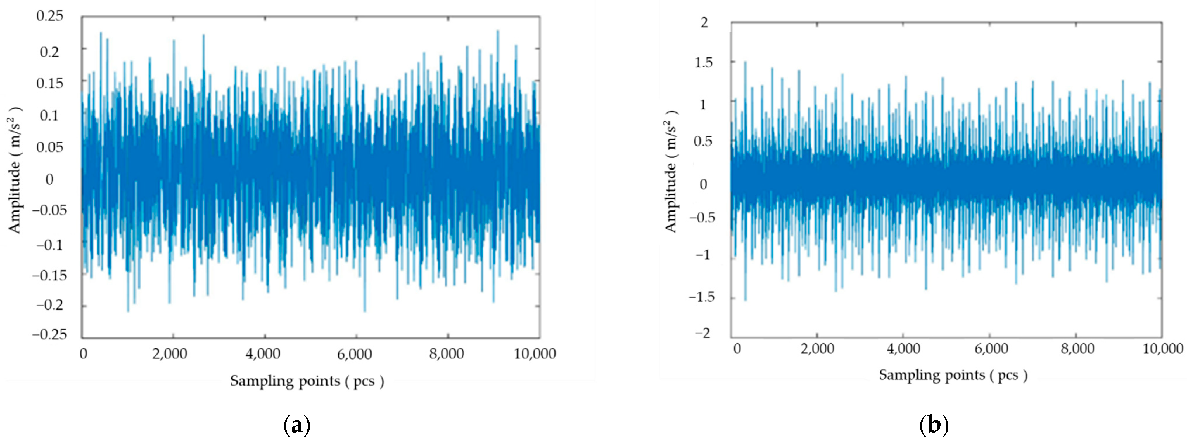
Taking machine failure, a typical and influential disturbance situation, as an example, a neural network-based disturbance monitoring model is established by processing the machine tool spindle vibration signal, and the disturbance monitoring of the machine is realized through neural network training and testing. In this study, the vibration signal of machine tool spindle collected from an aerospace plant is analyzed, and the vibration signals of normal and abnormal states are shown in
Figure 5.
Considering that the vibration signal is difficult to be used as the input vector of the neural network, this study uses wavelet packet technique to extract the energy features of the machine tool vibration signal. The collected vibration signal is decomposed by 3 layers of wavelet packets to extract the energy features of the machine tool mechanical vibration signal, and the energy features are used as the input data of the neural network. The distribution of the energy features of the machine tool in normal and abnormal conditions is shown in
Figure 6.
A total of 30 sets of data were obtained for feature extraction of the two state patterns, and some of the data are shown in
Table 3. From the obtained data, 20 sets of data are selected to train the neural network, and the remaining 10 sets of data are used as the neural network test data, where category 1 indicates the normal state and 2 indicates the abnormal state.
The wavelet packet energy feature vector of the collected machine tool vibration signal is used as the input vector, and the learning vector quantization (LVQ) neural network is used for training and testing. The input layer of LVQ neural network was 8 neurons, which correspond to 8 feature quantities of the input data. The output layer was 2 neurons. When the input vector is closest to the competing layer neuron, the competing layer neuron is activated, and the output layer neuron connected to this competing layer neuron has a value of 1 and the other output layer neuron has a value of 0. The output is “1 0” for category 1 and “0 1” for category 2 The number of competing layer neurons is calculated using Equation (1).
where
Nh is the number of neurons in the hidden layer,
Ni is the number of neurons in the input layer,
No is the number of neurons in the output layer,
Ns is the number of samples in the training set, and
is a real number from 2 to 10.
After several training sessions, the number of competing layer neurons was finally set to 5, and the learning rate was 0.01. The trained model was used to classify the test set data. The LVQ neural network test results are shown in
Table 4.
When applying the neural network to monitor the disturbance, if the disturbance occurs in the test result but not in the actual test, the parameters of the neural network model need to be adjusted, and the neural network needs to be trained according to the test data and historical data. Conversely, if the test result is that the disturbance does not occur, but the actual test result is that the disturbance occurs, then the disturbance situation needs to be processed. The virtual workshop model needs to be updated, the rescheduling scheme needs to be generated, and the production will be carried out according to the new scheduling scheme after simulation. In addition, the neural network needs to be trained according to the current disturbance situation to improve the accuracy of the neural network test.
5. Dynamic Scheduling Strategy and Case Analysis Based on Digital Twin
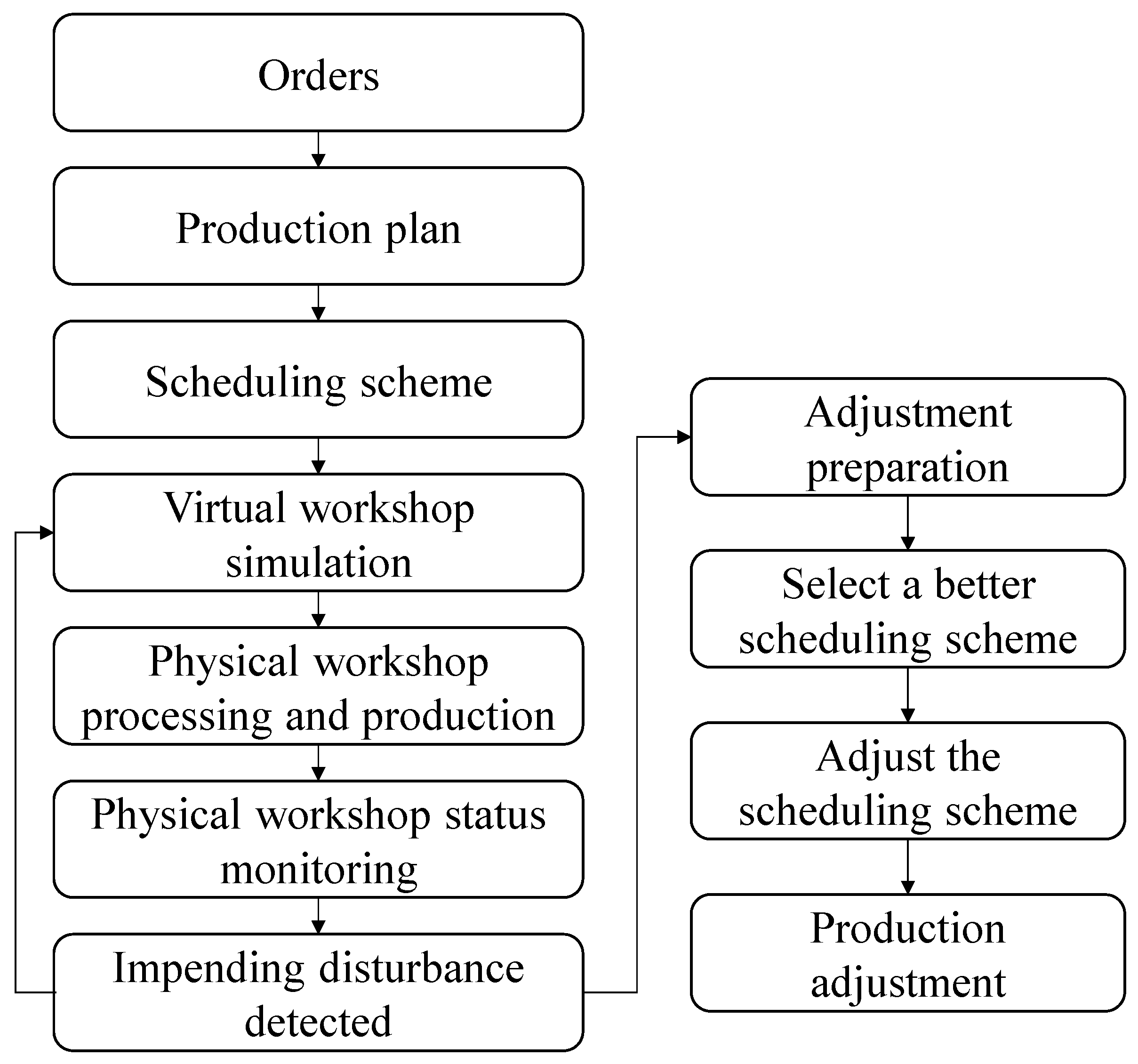
The digital twin workshop production scheduling is based on the virtual and real interaction between physical workshop and virtual workshop. According to the monitoring results of the above vibration signals, when a disturbance is detected, the processing task on the machine will be cancelled. Then the rescheduling strategy is used to generate the rescheduling scheme. The workshop production scheduling strategy based on digital twins is shown in
Figure 7. Through the state monitoring and disturbance monitoring of the physical workshop, the upcoming disturbance is monitored and the adjustment preparation is made in advance. Different scheduling schemes are simulated in the virtual workshop, and the better scheduling scheme is selected. After the preparation is completed, the production processing is carried out according to the new scheduling scheme.
5.1. Basic Assumptions and Mathematical Models
According to the disturbance, the dynamic scheduling problem should consider the workpieces, processes, available machines, and the available time of workpieces and machines. The assumptions of the workshop dynamic scheduling problem model in this paper are as follows:
- (1)
All workpieces can be processed at the rescheduling time.
- (2)
All machines can only be used after the previous process is completed.
The optimization objective includes minimizing the completion time (
) and minimizing the total energy consumption (
). The mathematical model is expressed as follows:
where
t is the time when disturbance occurs,
Q is the number of machines in total,
w is the number of machines available for unfinished process when disturbance occurs,
is the start processing time of the
y-th operation of
x-th workpiece in the initial scheduling scheme, and
is the start processing time of the
y-th operation of
x-th workpiece in the rescheduling scheme.
Equation (2) indicates that the start processing time of each process rescheduling scheme of each workpiece cannot be less than the start processing time of its initial scheduling scheme. Equation (3) indicates that the number of machines available for each process rescheduling scheme of each workpiece cannot exceed the number of machines available for its initial scheduling scheme. Equation (4) shows that the start processing time of each process rescheduling scheme of each workpiece is after the disturbance time
5.2. Evaluation Index of Dynamic Scheduling
Workshop dynamic scheduling should consider not only the basic performance index of the processing completion time of the rescheduling scheme, but also the stability of the rescheduling scheme after the disturbance event. Because the implementation of the rescheduling scheme requires material preparation, workpiece transportation, machine adjustment, etc., if the rescheduling scheme deviates too much from the initial scheduling scheme, it will have a certain impact on the production process. The evaluation index of dynamic scheduling includes time deviation and machine deviation.
5.2.1. Time Deviation
The time deviation (
PD) is the sum of the absolute value of the difference between the processing time of each process in the rescheduling scheme and the initial scheduling scheme. The smaller the time deviation, the better the stability of the rescheduling scheme.
where
x is the number of each workpiece,
W is the number of workpieces to be processed,
y is the y-th process of each workpiece, and there are
T processes in total.
5.2.2. Machine Deviation
Machine deviation (
MD) reflects the number change of processing operations on each machine in the rescheduling scheme. The smaller the machine deviation, the better the stability of the rescheduling scheme.
where
d is the machine index number,
indicates the number of processing operations on the machine in the initial scheduling scheme and
indicates the number of processing operations on the machine in the rescheduling scheme.
5.2.3. Comprehensive Evaluation Index
The comprehensive evaluation index (
CEI) is the weighted sum of the processing end time (
), energy consumption (
), time deviation (
) and machine deviation (
) of the normalized scheduling scheme.
where
is the weight coefficient,
is the number of the weight coefficient, there are
weight coefficients, and the sum of each weight coefficient is 1.
According to the actual situation, different weight coefficients are set for each index to comprehensively evaluate the rescheduling scheme.
5.3. Case Study
5.3.1. Initial Scheduling Scheme
The production task was to process 12 different workpieces. There were 6 processes for each workpiece and 8 available processing machines. The available processing machines and the processing time for each workpiece are shown in
Table 5 and
Table 6, and the power of each machine is shown in
Table 7.
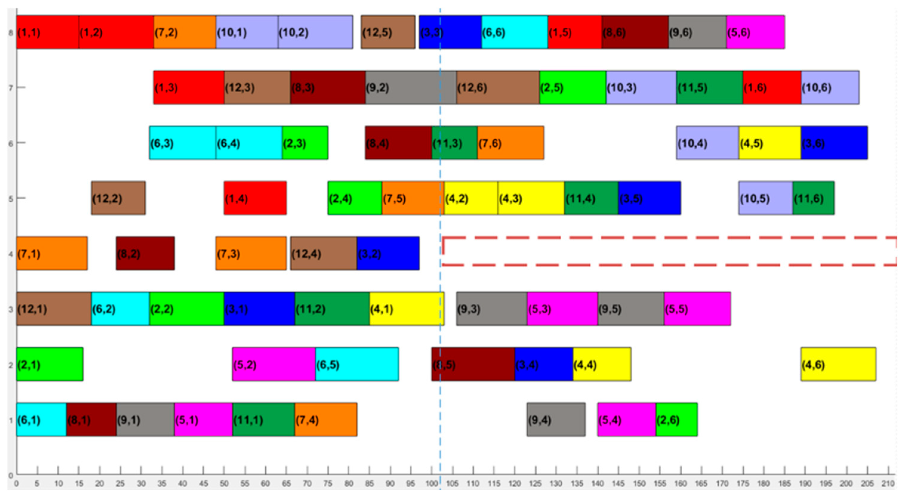
The digital twin service system generates a 12
6 scale initial scheduling scheme, as shown in
Figure 8.
In the figure, the horizontal coordinates represent the shop machining time and the vertical coordinates represent the machine number. Squares of the same color in the coordinate system represent the same workpiece, and the numbers in the squares are workpiece number and process number. For example, the red square in
Figure 8 represents workpiece 1, where the red square numbered (1, 1) is the first process of workpiece 1, which is machined on machine 8 during the time period 0–10. The processing end time of the initial scheduling scheme is 197 min, and the energy consumption is 2354 kW·h.
5.3.2. Complete Rescheduling Strategy Scheduling Scheme
In the digital twin environment, 12
6 scale production tasks were in the production process according to the original scheduling scheme. The digital twin service system obtained the wavelet packet energy of the vibration signal of the machine 4 spindle at time T1. It is different from the normal state wavelet packet energy spectrum distribution. The digital twin service system used the neural network to test its abnormal state, judge that machine 4 will fail, and trigger the rescheduling process. At time T1, the workpiece being processed on each normal machine continued to complete processing. The remaining processes on the faulty machine and the non-faulty machine formed a scheduling set and the scheduling algorithm was used to generate a rescheduling scheme. The resulting scheduling scheme is shown in
Figure 9.
When digital twinning technology was not used, machine 4 fails at time T2. The workpiece processed on machine 4 needs to be reprocessed. The unprocessed process on machine 4 was arranged to other alternative machines. The remaining processes on the faulty machine and the non-faulty machine formed a scheduling set and the scheduling algorithm was used to generate a rescheduling scheme. The resulting scheduling scheme is shown in
Figure 10.
It can be seen from
Figure 8,
Figure 9 and
Figure 10 that the digital twin system finds the abnormality of the machine at an early time by monitoring the vibration signal of the machine spindle, so as to adjust the scheduling scheme. Without using the digital twin system, the machine will make adjustments after it breaks down and sends out an alarm. The adjustment time is late. Compared with the initial scheduling scheme, because the processing task is not arranged on the faulty machine, the machine and processing time used in the workpiece process in the rescheduling scheme have changed greatly. Based on the scheduling of digital twin system, it is found that the disturbance is earlier, and the rescheduled workpiece processes are more than those without digital twin system. It can make adjustments earlier according to the disturbance and make more reasonable arrangements for the workpiece process.
As shown in
Table 8, compared with the scheduling scheme without digital twin, the scheduling scheme based on digital twin has 3.4% less processing end time, 2.4% less energy consumption, 41.9% less time deviation and 17.6% less machine deviation. The time deviation and mechanical deviation in
Table 8 are calculated by using Equations (5) and (6) above. It can be seen that the processing end time and energy consumption of the scheduling scheme based on the digital twin complete rescheduling strategy are less than those of the scheduling scheme without the digital twin system. The time deviation and machine deviation of the scheduling scheme based on digital twin complete rescheduling strategy are mostly smaller than those of the scheduling scheme without the digital twin system.


