1. Introduction
Ultrasonic-guided wave-based inspection techniques are very promising for non-destructed testing (NDT) and structural health monitoring (SHM) and are the primary techniques for long-range damage detection and characterization of plate-like structures. The guided Lamb waves propagate within the interior of the objects under investigation. The Lamb wave’s fundamental A0 and S0 modes are widely used as they can be relatively easy to excite and are sensitive to various types of defects, which are found especially in composite materials.
Contemporary technologies include the employing of thin films and composite plate materials. There is a special class of widely used, very thin (~0.1 mm) materials—plastic tapes and films such as clear polyvinyl chloride films [
1]. Polyvinyl, also known as poly (vinyl chloride) or PVC, is the third-most widely produced synthetic plastic. The production of polyvinyl chloride films in Europe reaches five million tons annually [
2]. During the manufacturing of PVC films, various defects such as wrinkles, holes, rough surfaces, and thickness variations can arise.
Ultrasonic methods using guided waves enable the investigation of key elastic properties of materials that cannot be assessed by merely using other methods, for example excitation by lasers [
3,
4], electrostatic excitation methods [
3], or electromagnetic acoustic transducers [
5,
6]. These guided waves are currently used for the non-destructive testing and evaluation (NDT) of thin film type materials [
7]. Usually, they are excited when the vibrations of an acoustic transducer are transferred to the investigated item by direct contact via a coupling liquid. The contact liquids are impossible to use in many cases, as the investigated item may be contaminated, damaged or otherwise negatively affected [
8,
9]. This is relevant in the cases of thin films or composite structures. Some defects are detected by optical methods, but some defects such as holes and especially thickness variations can be better found by ultrasonic methods using guided waves [
10,
11,
12]. Therefore, air-coupled ultrasonic investigation using guided waves can be a very attractive technique for the investigation of such type of materials.
The attenuation of ultrasonic waves in air and in the object under investigation increases with the frequency. The loss of ultrasonic signals may be reduced by generating guided waves while using lower frequencies [
13,
14,
15].
At lower frequencies, the velocity of the ultrasonic-guided waves in thin films may become lower than the ultrasound velocity in air, which complicates excitation and reception of ultrasonic signals by air-coupled methods [
16,
17]. Therefore, it is appropriate to develop novel air-coupled ultrasonic measurement methods based on the excitation and reception of guided waves for a study of such objects. Special problems arise in the case of excitation and reception of symmetrically guided wave modes, which require fundamentally new methods of excitation and reception.
The guided waves in thin film type materials may be excited via air gap in two different ways depending on the ratio of propagation velocities of ultrasonic waves in the material and air. When the phase velocity of the guided waves in the object is bigger than the ultrasound velocity in air, then the optimal incident angle of the ultrasonic wave incident from air onto the plate exists at which the biggest amplitude of guided wave is obtained. The propagating guided wave in a thin film then radiates a leaky wave into air, which may be used for air-coupled reception. This mode is commonly applied for detecting defects inside thin plates and film type materials as the leakage increases at the defective zone [
18,
19,
20].
In our previous investigations, we analyzed application of air-coupled linear phased ultrasonic arrays for excitation and reception of only the slow fundamental antisymmetric A
0 mode, in the frequency range in which the velocity of this mode is slower than the ultrasound velocity in air [
16,
17]. For the analysis of propagation of the ultrasonic wave through the air gap, the impulse response method was used [
16]. Propagation of the A
0 mode in a plastic film was calculated by the analytic time harmonic solution method [
14,
16,
17].
However, exploitation of the symmetric S
0 mode enables not only detection of various defects, but also evaluation of elastic properties of the item under a test [
20]. For example, simultaneously excited S
0 and A
0 guided wave modes enabled the measurement of thickness and Young’s modulus of thin PVC films [
21]. For practical applications, it would be very attractive to use it for the same ultrasonic air-coupled transducer or array. To our knowledge, a detailed analysis of the performance of such methods is still missing [
21]. For this purpose, we propose instead a single ultrasonic transducer to use linear air-coupled arrays, which can be electronically readjusted to optimally excite and receive the required guided wave modes. For the solution of this problem, we used a numerical simulation based on the application of finite element modelling.
The objective of this article was a numerical investigation of feasibility to excite different types of ultrasonic-guided waves, such as symmetrical S0 and asymmetrical A0 modes in thin plastic films with the same electronically readjusted linear phased array.
First, we simulated propagation of two fundamental A
0 and S
0 Lamb wave modes in thin plastic films using a single ultrasonic transducer. Second, to improve the excitation of the S
0 mode, a linear phased array was proposed for use. Calculations were performed using finite element methods (FEM). FEM has many advantages such as [
22]: it allows solving acoustic contact problems, to model bodies made of different materials; a curvilinear region can be approximated by means of finite elements of smaller dimensions, which enables the increase of modelling accuracy [
23]. FEA’s main advantage is that it produces a much more detailed set of results than experimental investigations and is often quicker and less expensive. Fundamentally, instead of tackling a big problem directly, we divided it into smaller and more easily solvable problems to attain a unique result for the system as a whole. The discrete model approximates the behavior of the real physical structure. However, provided that the discretization mesh is dense enough, the approximation is sufficient to accurately model reality [
24,
25,
26].
The numerical modelling was performed using the commercially available finite element software, Abaqus. Two numerous calculation methods, 3D and 2D, were used. Numerous calculations showed that the 2D technique significantly improves the computational efficiency compared to the 3D technique [
27,
28,
29].
The paper consists of four sections. In
Section 2, the numerical simulation of propagation of A
0 and S
0 guided wave modes in thin PVC plastic film is presented. The finite elements modeling results of A
0 and S
0 guided wave modes are described in
Section 3. In
Section 4, conclusions and discussion of the obtained results are given.
2. Finite Elements Models
Propagation of the guided A
0 and S
0 mode in the PVC film sample was simulated by the ABAQUS software package (Dassault Systemes, Johnston, Rhode Island, United States of America). The ABAQUS program was chosen for its high level of detail, manual design of the work piece, possibility of configuring the materials, and the very fine control of mesh; however, the ABAQUS program has no support for any materials and takes time to “setup” simulations as the user must manually set many simulation parameters. For the modelling of propagation of A
0 and S
0 modes in thin plastic films, two 2D and 3D calculation methods were chosen [
30,
31,
32,
33].
Modeling of elastic wave propagation was carried out by solving the following equation:
where [
M] is the structural mass matrix, [
C] is the element damping matrix, [
K] is the structural stiffness matrix, {
U} is the displacement vector, and {
F} is the load vector. The Abaqus Explicit software uses a central difference method to integrate the equation of motion in time [
25,
34]:
where Δ
t is the time step and
Three-dimensional models are in practice limited to small size models and low frequencies due to the required computational power to numerically solve the wave’s propagation tasks. They also require relatively time-consuming post processing before the results can be obtained. However, there is a significant difference in the computational time between two-dimensional (2D) FE models and more accurate 3D models.
First of all, a 3D method was used to simulate the propagation of guided waves excited by one element with the excitation zone of 5 × 1 mm, the center of which is at
x,
y = 0. The calculations were performed for polyvinyl chloride (PVC, London, UK). Dimensions of the PVC sample selected for simulation were 240 × 240 mm. For reduction of the computational time, only a quarter of the film with symmetry boundary conditions was modeled by the 3D method. The modeled structure of one excitation zone is shown in
Figure 1a. The simulation step in the time domain was set
dt = 1 μs. The strip-like piezoelectric element radiates an ultrasonic wave, which propagates via the small air gap and excites a guided wave in the thin plastic film. The excitation was introduced as the uniformly distributed 1 N 150 kHz force impulse in the transmitter area. The frequency of 150 kHz was selected because at such a frequency only the only two modes, symmetrical S
0 and antisymmetrical A
0, may propagate.
Second, a 2D method was performed simulating an A
0 and S
0 guided wave modes excitation zone of 1 mm. This schematic diagram with one excitation zone is presented in
Figure 1b. The excitation zone is placed
x = 50 mm,
y = 0 mm from the coordinate origin t at
x,
y = 0.
In
Table 1, some properties corresponding to the computational efficiency of the 3D and 2D methods are compared, which show that the 2D simulation method has a high speed and needs a relatively smaller memory than the 3D method.
The 3D model is very complicated and has some disadvantages: a large amount of data is required as input for the mesh used in terms of nodal connectivity and other parameters depending on the problem, and requires longer execution time. Our 3D model data is about 120 GB, with numbers of elements in the model being over 6 million, a calculation time of about 5 h, and where it is impossible to see the S0 guided wave mode. For this reason, other simulation results were obtained by the 2D modeling method. In the 2D simulation method, we used a finite element size of 15 μm in the model, which is ~4.2 times smaller than in the 3D model and the length of the PVC film is 2.5 times longer than the 3D model.
The values of the phase and group velocities of the A
0 and S
0 guided waves modes in PVC film were calculated using the Semi Analytical Finite Element (SAFE) method. The parameters of the clear PVC thin film used for calculations are presented in
Table 2 [
35].
The calculated phase and group velocities versus frequency are shown in
Figure 2. From the simulation results it follows that even in the frequency range up to 3.2 MHz, only two modes, symmetrical S
0 and antisymmetrical A
0, may propagate. For numerical simulations the frequency of the excitation signal 150 kHz was selected because at such a frequency only those two modes may propagate. The ultrasound phase velocity of the A
0 mode at the frequency is 232 m/s and the group velocity is 448 m/s are presented by red and blue colors in
Figure 2. The ultrasound phase and group velocities of the S
0 mode do not depend on a frequency and are 1595 m/s. In
Figure 2 they are indicated by a solid red horizontal line. The ultrasound velocity in air of 343 m/s is presented by a dotted line in
Figure 2. Please note that the phase velocity of the A
0 mode is slower than the ultrasound velocity in air up to 240 kHz, therefore its air-coupled excitation by a classical method using deflected ultrasonic transducer looks impossible. However, we shall demonstrate that it is possible using a linear air-coupled array. The waveform and the spectrum of the excitation force are shown in
Figure 3 and
Figure 4. In the
Figure 3 and
Figure 4 n.u. represents normalized units. The excitation frequency is
f = 150 kHz, and the numbers of periods is
n = 3.
The simulation results obtained by the 2D and 3D FEM methods are presented in the following
Section 3.
3. Finite Elements Modeling Results
3.1. Single Transducer Model
The main idea of the performed numerical investigation was to analyze possibilities to excite not one but a few guided wave modes possessing very different propagation velocities and distributions of displacements with the same linear phased array. For such purpose symmetrical S0 and antisymmetrical A0 modes fit very well. The biggest challenge is the excitation of the S0 mode, as in this mode, the in-plane displacement component is much bigger than the off-plane component, e.g., normal to the surface of the film. For excitation of those guided waves we shall use a linear air-coupled array consisting of eight strip-like elements with radiating apertures of 5 × 1 mm.
The model of the thin PVC film was meshed using shell elements and the propagation of guided waves was first simulated by the 3D method. The thickness of the PVC film was l = 135 μm. The dimension of the finite elements was 62.5 μm, the numbers of elements in the model were 6 816 600 and only a quarter of the film with symmetry boundary conditions was modelled. Such a dimension is close to 1/20th of the S0 wavelength λ = 10.6 mm at the analyzed 150 kHz frequency.
In order to evaluate the influence of ultrasonic field spreading due to a diffraction in the plane of the film, calculations by the 3D method were performed for a single array element with a rectangular aperture with dimensions 5 × 1 mm. The air-coupled ultrasonic transducer usually is placed very close to the film surface, for example 1 mm. In such case the simulation of the propagation of ultrasonic wave through the air gap can be replaced by the force acting on the surface of the film. This force is uniformly distributed in the rectangular area corresponding to the radiating aperture 5 × 1 mm of the array single element.
The simulated spatial distributions of the particle velocity
y component at the time instant
t = 200 µs is shown in
Figure 5a. The B scan of this in-plane particle velocity component along
y axis is presented in
Figure 5b. The waves are more strongly radiated along the
y axis direction due to directivity properties of the excitation zone.
In the B scan (
Figure 5b) we have the signals measured at many positions along the same direction, the phase velocity can also be estimated by taking two signals measured at neighboring positions and estimating the propagation time of a particular phase point between those positions.
Such an estimation gives the group velocity 424 m/s, what allows concluding that a single array element excites mainly a strong A
0 mode in the thin film. There are very weak traces of the S
0 mode propagating with the velocity 1540 m/s, however they look so weak that are not suitable for any measurements. This 3D simulation was performed using shell elements; therefore, we decided to check if the simulation by 2D FEM exploiting conventional finite elements allows for the revealing of a better S
0 mode. On the other hand, the 2D FEM requires a smaller number of elements and much shorter simulation time (
Table 1).
The schematic diagram with one excitation zone is shown in
Figure 1b. The length of the simulated PVC film is 300 mm. The excitation zone was placed at the 50 mm from the origin of the coordinates. The B scan of the in-plane particle velocity component in the PVC film obtained by 2D simulation is presented in
Figure 6. The ultrasonic pulses of the in-plane particle velocity at two different distances from the excitation zone (x = 50 mm, y = 0 mm) are shown in
Figure 7a,b.
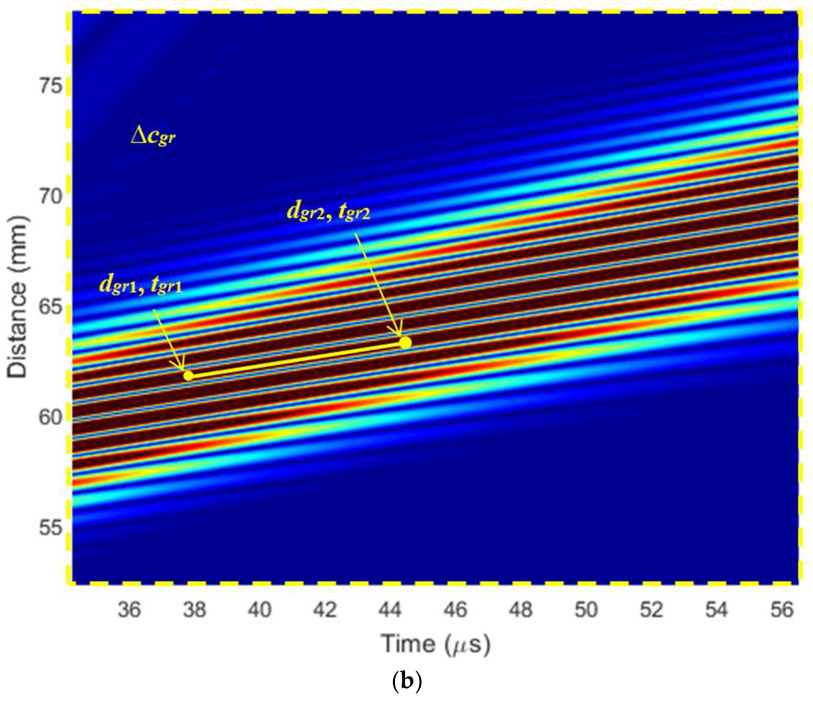
In order to identify what mode (or modes) is actually excited by a single array element the propagation velocity of the waves shown in
Figure 5a should be evaluated. The phase velocities are usually found from the distances ∆
dph and ∆
dgr, which are covered by a particular phase point during the time intervals ∆
tph and ∆
tgr:
In the presented B scan we can see better the excited fast S0 mode. The S0 and A0 modes reflected from the boundaries of the sample are also seen.
The ultrasound velocities of the waves shown in the B scan were calculated by Equations (5) and (6) and compared with the velocities of the guided waves modes obtained by the Semi Analytical Finite Element method (
Figure 2). It is possible to conclude that there is a strong A
0 mode propagating with the group velocity
cgr = 464 m/s and the phase velocity
cph = 233 m/s. The zoomed B scan of A
0 phase mode is presented in
Figure 6b. The S
0 wave mode propagating at the phase velocity of
cph = 1584 m/s can also be seen in
Figure 6a.
The ultrasonic pulses of the particle velocities at two different distances
x = 210 mm and
x = 300 mm are shown in
Figure 7a,b. At the distance 210 mm (
Figure 7b), two pulses are seen. The first pulse is the directly propagating pulse and the second is the pulse reflected from the edge of the PVC sample. Please note a lower amplitude of the S
0 pulse at the distance x = 210 mm. From the results obtained it follows that a single element with the width 1 mm excites not only A
0 but also S
0 mode.
3.2. Linear Array Model
Therefore, we decided to check if it was feasible to excite S
0 mode by a properly phased linear array placed close to the film surface. For this purpose, we proposed a single ultrasonic transducer to use linear air-coupled arrays, which can be electronically readjusted to optimally excite and receive the required guided wave modes. This linear air-coupled array can improve the excitation of S
0 mode. Numerical investigation was performed simulating the excitation of the S
0 guided wave mode by a planar linear array. The schematic diagram is presented in
Figure 8. The array consists of eight strip-like elements of 1 mm width. All spacings between elements should theoretically be equal to
= 5.3 mm. For the excitation of the S
0 modes, the linear air-coupled array elements are excited successively with the time delay necessary for this mode to propagate the distance between the adjacent elements. The delay time between elements is ∆
τ = 3.3 μs and calculated by the following Equation (7):
where
is the wavelength of the S
0 mode,
l is the thickness of the thin PVC film, and
f is the frequency. In such case each strip-like piezoelectric element of the linear array excites the S
0 mode in phase, thus increasing the amplitude of the propagating guided wave. The B scan of the
x component in-plane particle velocity of the array is presented in
Figure 9.
For identification of the excited Lamb wave modes shown in
Figure 9, we calculated propagation velocities of the simulated modes similar to the single element case and compared them with velocities determined by the Semi Analytical Finite Element method (
Figure 2). From the numerical simulation, it follows that the A
0 mode propagates with a group velocity
cgr = 459 m/s; the A
0 phase velocity is
cph = 244 m/s. The S
0 mode propagates with the phase velocity of
cph = 1591 m/s (
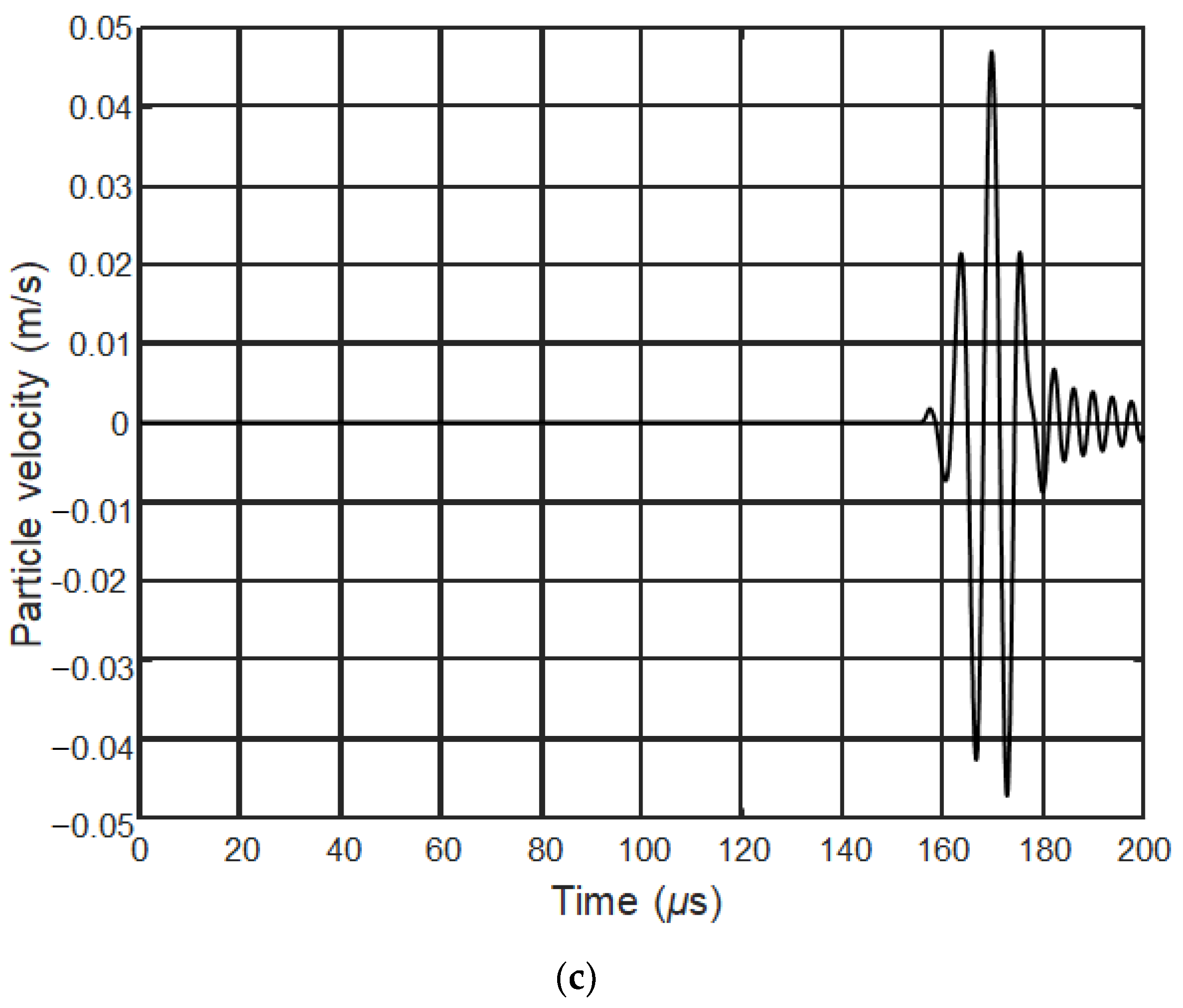
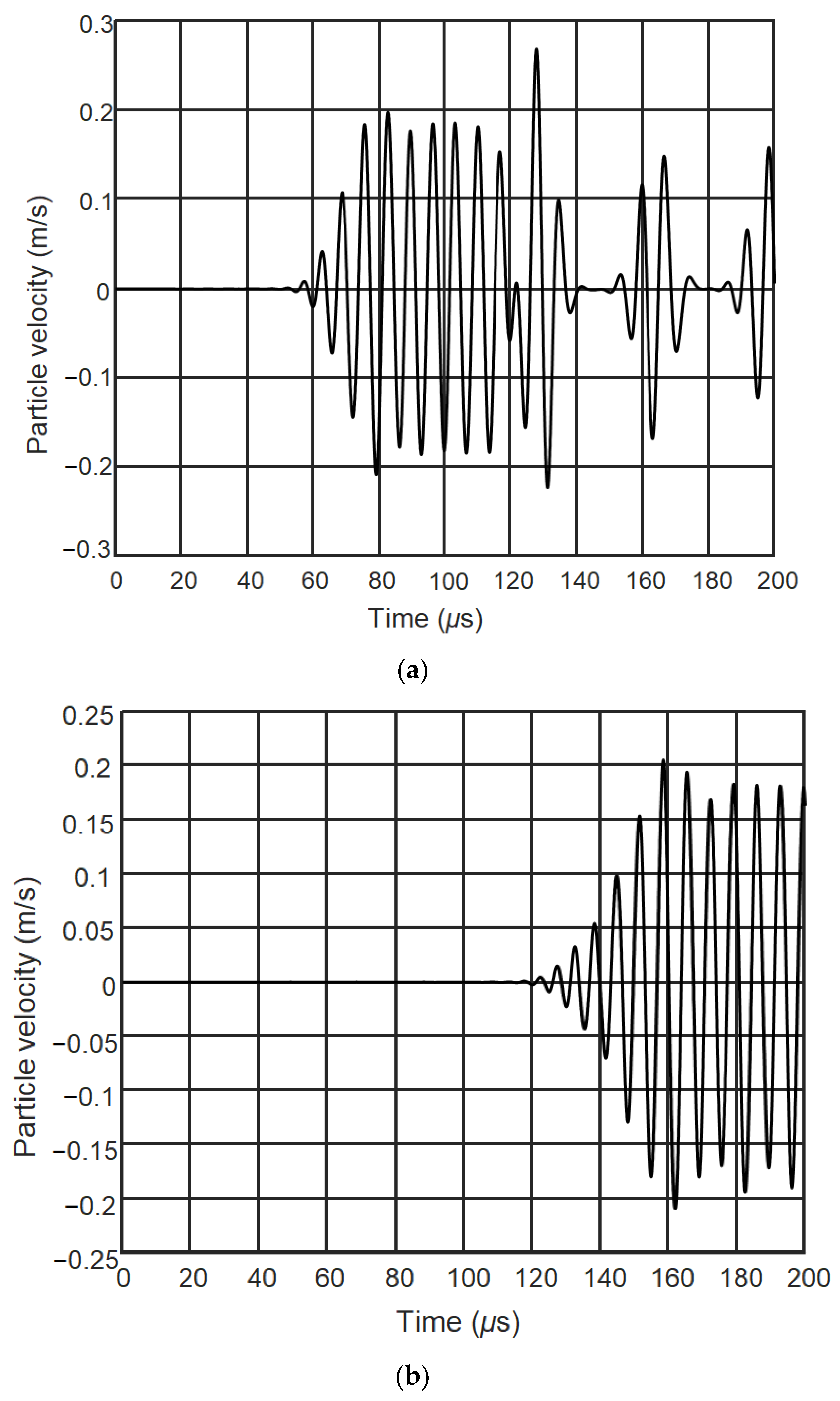
Figure 9). The ultrasonic pulses at three different distances from the excitation zone
(x = 50 mm,
y = 0 mm) are presented in
Figure 10a–c. The first pulse in those figures is the S
0 mode, the second pulse corresponds to the A
0 mode. The ultrasound velocities of the ultrasonic pulses at two different distances from the excitation zone (
Figure 10b,c) are calculated by Equations (5) and (6). The obtained S
0 mode phase velocity in this case is
cph = 1551 m/s, which is very close to the velocity obtained by the Semi Analytical Finite Element method.
The particle velocity amplitude at the excitation zone (
x = 50 mm,
y = 0 mm) is 0.05 m/s. The array excitation zone is presented in
Figure 8. The planar linear array improves the excitation of S
0 mode eight times in comparison to when the excitation zone is 1 mm.
Although the amplitude of the A0 mode is bigger than the S0 mode at longer distances, both modes may be exploited for simultaneous measurements because they arrive at different time instants.
For the excitation of the A
0 mode at 150 kHz frequency we proposed to use the same phased array with spacings between array elements equal to
= 5.3 mm, however, with introduced delays between the excitation instants of the array elements necessary for the excitation of the A
0 mode:
The delay time between elements in this case is ∆τ = 22.8 μs. The linear air-coupled array elements become excited successively with the time delay necessary for this mode to propagate the distance between the adjacent elements.
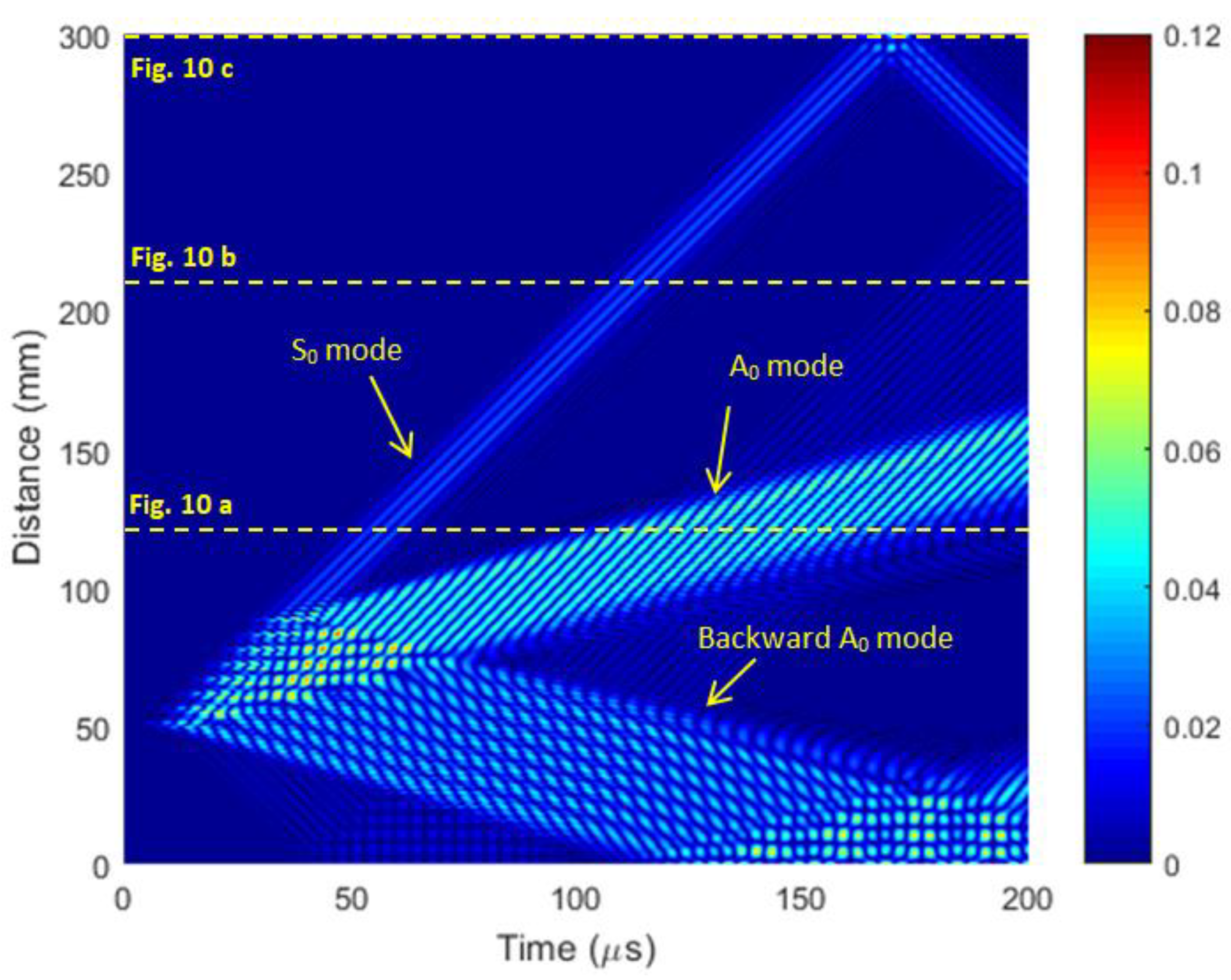
The B scan of the
y component off-plane particle velocity of the array is presented in
Figure 11. The A
0 mode is more strongly radiated along the
y-axis direction. The start excitation point of the linear air-coupled array is shifted 50 mm from the origin of the coordinates
x = 0 mm,
y = 0 mm. Each element of the array excites two A
0 mode waves, propagating forward and backward (
Figure 11).
The waveforms of the ultrasonic signals at different distances, 75 mm, 110 mm, and 125 mm are shown in
Figure 12. The distances are indicated in
Figure 11 by the horizontal dashed lines. The forward propagating A
0 mode is properly phased, which results in a single ultrasonic pulse at distances longer than the length of the phased array. Contrarily, the backward propagating wave is not phased and, in this case, the backward wave is propagating not a single ultrasonic pulse, but a series of ultrasonic pulses generated by each element of the array which are shown in the B scan by parallel beams.
It is necessary to point out that in the A
0 mode the off-plane particle velocity component prevails; therefore, it is presented in
Figure 11 and
Figure 12. From the results presented it follows that there is only a strong A
0 mode excited, which was confirmed by calculating phase and group velocities from the simulated waveforms and comparing them with the corresponding velocities obtained by the Semi Analytic Finite Element method (
Figure 2).
The phase and group velocities obtained from the numerical simulation results at the frequency 150 kHz are as follows: group velocity cgr = 458 m/s and phase velocity cph = 248 m/s. For comparison, the phase and group velocities of the A0 mode calculated by the Semi Analytic Finite Element method are cgr = 448 m/s and cph = 232 m/s, which are very close to the results obtained from the numerical simulations. This means that by the proposed excitation method, only a strong A0 mode is excited in a thin PVC film.
4. Conclusions and Discussion
There are some tasks in which applications of a few different guided waves enable us to obtain more information about structures under a test. For example, the measurement of phase velocities of symmetrical S
0 and antisymmetrical A
0 guided wave modes allowed us to determine the thickness and Young‘s modulus of thin PVC films [
21]. The main problem is how to excite such modes in thin films especially using air-coupled methods.
The performed numerical modelling by 2D and 3D finite element methods showed that for such purpose, a contactless linear phased array might be successfully exploited. It was shown that the most serious problem is the excitation of the symmetrical S0 mode, as in this mode the biggest challenge is the in-plane displacement component, which is almost impossible to excite by a single ultrasonic transducer. For a solution of this problem, we proposed using a linear phased array where the elements of which are excited by electric signals with properly selected delays. The delays of the excitation instants between adjacent elements are equal to the propagation time of the S0 mode.
For the excitation of the A0 mode we proposed using the same phased array, except the delays between adjacent elements of the array in this case were equal to the propagation time of the antisymmetrical A0 mode. In our case, at the frequency 150 kHz this delay was ∆τ = 22.8 μs, e.g., 6.9 times longer than the delay for the excitation of the S0 mode.
The obtained results clearly demonstrate feasibility to excite efficiently different guided wave modes with very different phase velocities using the proposed method based on an electric readjustment of the same phased array.


