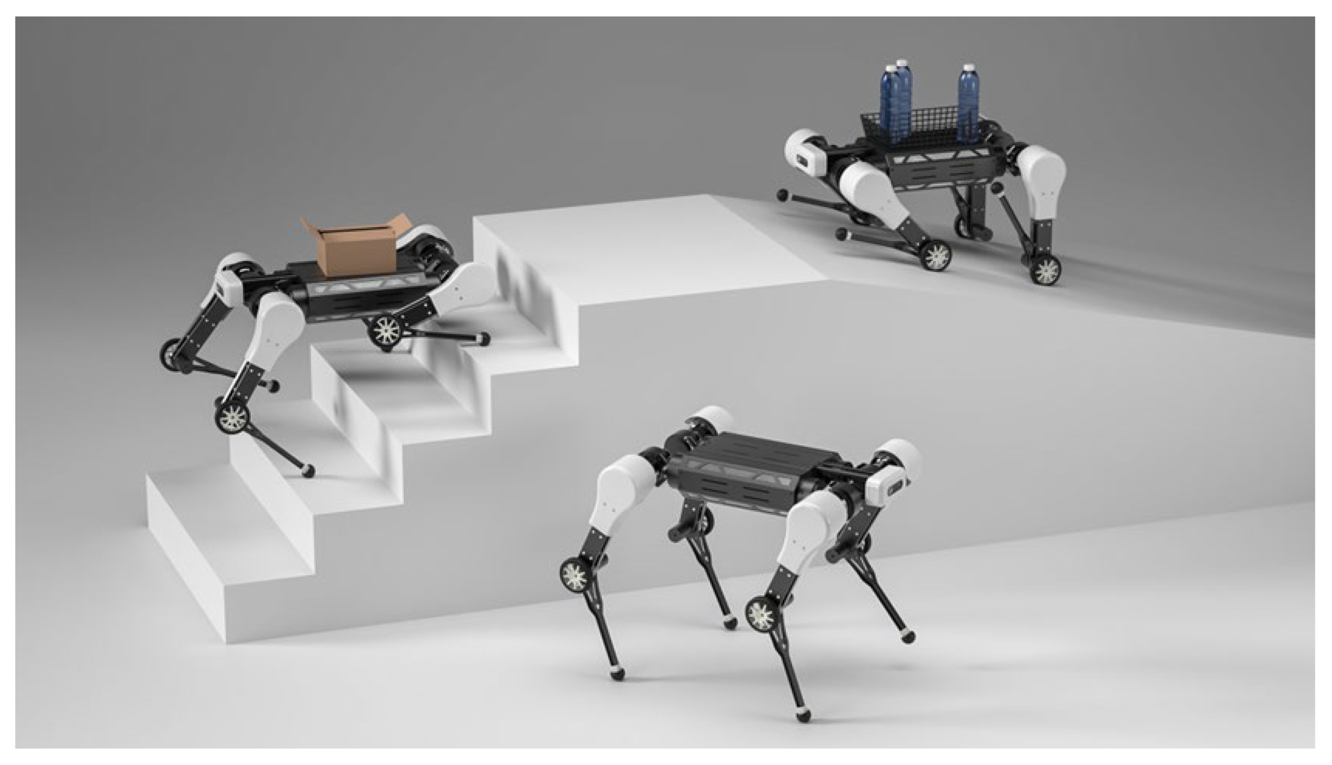
Article

A Wheels-on-Knees Quadruped Assistive Robot to Carry Loads

Department of Industrial Design, Guangdong University of Technology, Guangzhou 510090, China
*
Author to whom correspondence should be addressed.
Appl. Sci. 2022, 12(18), 9239; https://doi.org/10.3390/app12189239
Submission received: 28 August 2022 / Revised: 11 September 2022 / Accepted: 12 September 2022 / Published: 15 September 2022

Abstract

:
This work introduces a high-performance, quadruped-assistive-robot expandable platform with wheel–leg mode transformation functions. The robot platform is designed for transporting goods in residential areas such as apartments, private houses, and office buildings. It is capable to move fast on flat ground on wheels or use legs to move in other places, especially for moving on and off residential staircases and wheelchair accessible ramps. To achieve higher load capacity and combine the knee joint with the drive wheel, we designed a compact torso–leg structure, driving the lower link through a ligament-like structure. Because the distance between the wheel and the torso is short, the mass centroid drops and the force arm caused by the load is reduced; the designed sample robot is capable to transport uniform mass loads up to 15 kg while keeping it affordable. The proposed ligament-like transmission structure also ensures the torso’s even gesture and load capability in its walking mode. Gait motion planning, finite element analysis, and task-oriented simulation have been conducted to prove its applicability and feasibility when given a heavy load to transport across flat and staired scenarios.

1. Introduction

In the post-epidemic era, assistive robotics have been proved capable in disinfection, delivering urban rescue facilities, and assisting individuals under quarantines for disadvantaged society, especially for disabled and elder people who are prone to expect external assistance [1,2]. Pandemic-related quarantine leads to prolonged isolation of individuals from social interaction, which may cause disadvantaged groups to face more challenges in their daily lives [3].
The COVID-19 pandemic has introduced opportunities for an assistive robot for disadvantaged communities, which would maintain individuals’ necessary daily life activities and socioeconomic functions [4].
At times when disadvantaged groups must face the trivial things in life alone, assistive robots could be deployed to provide continued social interaction and adherence to treatment within communities. In domestic lives, assistive robots have gradually become lightweight and miniaturized while undertaking the tasks conventionally carried out by humans. Čaić et al. investigated the potential roles for service robots (i.e., socially assistive robots) in value networks of elderly care [5]. Van Assche et al. provide valuable insights for the care of lonely and occupationally deprived older adults [6]. When going out, assistive robots can carry items of certain load. Additionally, robots have many extendable possibilities. For some scenarios, they may even participate in tasks that used to be accomplished by humans. Obviously, assistive robots have already gone far beyond conventional simple tools.
Yet, robotics has proved capable in disinfection, delivering urban rescue facilities, and assisting individuals under quarantine. As epidemics escalate, the significance of robots for disadvantaged groups is becoming increasingly emphasized. As for hybrid robots with compound functionalities, most assistive robots are mobile robots. Generally speaking, there are three categories of mobile robots: wheeled robots, tracked robots, and legged robots [7]. Wheeled robots have better stability, controllability, and higher work efficiency, while legged robots have better maneuverability and obstacle-crossing capabilities. Wheeled and tracked robots perform better on flat surfaces; however, legged robots, similar to animals, can work in any complex terrain [8].
Compared with six-legged or bipedal robots, quadruped robots are easier to drive, control, and design [7]. In general, the actuator system of legged robots is divided into hydraulically and electrically driven systems. Hydraulic actuators have higher force density and impact resistance, but they also have certain drawbacks such as hydraulic source requirements and easily produced liquid leakage. Therefore, hydraulic actuators are generally used in very powerful robot systems that have very large self-weights, with system designs that are also extremely complex and costly [9]. Hydraulically driven quadruped robots, such as the Baby Elephant [10], Big Dog, and LS3 [11,12] robots, have extremely high load capacities and are mainly used for outdoor tasks. Electrically driven actuators are being chosen increasingly more for quadruped robots such as Spot, and they perform better at indoor tasks. More variations have taken place for serving specified tasks: Bai et al. introduces a minimalistic design of a monopedal robot with C-shaped legs that can achieve multiple locomotion modes such as walking, leaping, and backward and forward flipping [13]. Setiawan and Thomaszewski discuss quadruped robot motion with two motors using max-plus algebra [14].
Wheel–foot quadruped robots combine the advantages of both wheeled and quadruped robots and are capable of both rolling on a flat surface and moving over a rough terrain [8]. When a robot has more than three wheels or feet, it is very easy for the robot to maintain balance [15]. A wheel–foot quadruped robot, therefore, has significant carrying advantages. The Paw robot proves the viability of a wheel–foot quadruped robot [16]. It is a quadrupedal robot with wheels on the distal ends of its compliant legs that use a bounding gait to move. It has strong athletic ability, but it is not optimized for an urban environment and its performance does not meet the high stability requirements of transportation work. In recent years, several commercial wheel–foot quadruped robots have been developed, such as the Swiss-Mile and Tencent 2nd Generation Max robots that use the current mainstream quadruped structure with a high-performance motor actuator. These wheel–foot robots have excellent performances, but they are either poor at transporting loads or suffer from high cost.
In Table 1, we briefly list the work scenes, force transmissions, and mobility features of relevant quadruped robots. Kirin, a versatile mobile platform for carrying a high payload, is designed to carry a load as much as 125 kg with self-weight 50 kg, with electric actuators in a lifting-related scenario [17]. HyQ2Max has demonstrated that additive manufacturing (AM) can produce highly integrated hydraulic components with reduced weight and greater complexity [18]. Swiss-Mile, an exemplary classic and successful commercial quadruped robot, announced potential for winning in multiple fields with wheels on feet [19]. ANYmal, a quadrupedal robot features outstanding mobility and dynamic motion capability [20], but lacks the mobility advantage of wheels; the same applies to mini cheetah [21]. Lywal, is a leg–wheel transformable quadruped robot that can switch to leg-mode and wheel-mode for locomotion, and claw-mode for picking up and transport functions [22]. To our best understanding, modern quadruped robots with considerable payload capability still require high expense in both acquisition and maintenance. The commercially available solutions are far from setting proper balance between payload capability and feasibility of being a family partner that helps people practically and efficiently.
In this paper, we propose a wheels-on-knees, quadruped-assistive-robot platform that is able to transport loads within urban environments. It is extendable on various tasks while keeping the cost affordable by using a regular civilian-grade motor, connector, and most materials. For the size of this robot, most types of residential staircases and common wheelchair accessibility ramps are taken into consideration. Moreover, a ligament-like transmission structure is proposed, using wire ropes for the knee transmission, which can withstand a large load. We propose motion plans for two cases, i.e., a walking gait and a rolling motion, which ensure that the torso is close to horizontal while walking, going up and down stairs, and traveling over ramps. The design of the introduced robot is shown in Figure 1.
The contribution of this work is as follows:
  • We introduce a household-affordable, high-performance quadruped-assistive-robot platform for performing transportation tasks, designed for disadvantaged people in post-epidemic context.
  • We introduce a ligament-like transmission structure that uses wire ropes to the knee transmission to withstand large loads.
  • We innovatively design the wheels-on-knees transportation mode with ligament-like transmission together that drops the force caused by loads’ shake in movements. To our best understanding, we are the first to specifically adapt this design to enhance the transportation capability on quadruped assistive robots.
  • Gait motion planning, finite element analysis, and task-oriented simulation are conducted to prove its applicability and feasibility for given heavy load transportation across flat and staired scenarios.
In Section 2, we describe the structural design of the robot; first, we describe the selection of actuators and the structure and materials of each component, and we then show the process of verifying the strength of a structure using finite element analysis. In Section 3, we propose motion plans for the robot as it walks and rolls. In Section 4, we show the verification of load capacity and gait planning using a dynamic simulation. In Section 5, we discuss the significance of the robotic platform and the implications of the research.

2. Design of the Quadruped Robot

The robot is designed to weigh 28 kg, including the battery, with a maximum load capacity of 15 kg, which is as much as 54% of its self-weight. The design physical parameters are shown in Table 2. The speed is as fast as 2.5 m/s in wheeled mode.
Twelve CubeMars AK80-64 dynamic actuators are applied to drive the power transmission structure. Moreover, four DJI m3508 actuators are adapted to power the wheels. Two 48 V 12 Ah lithium battery packs are plugged within the torso to meet the demands of the high-performance dynamics, as indicated in Table 3.
As shown in Figure 2, each leg of the robot has three degrees of freedom; the knee can bend in two directions with a minimum bending angle of 30°, and it can easily traverse various urban terrains.

2.1. Structure and Actuators of the Legs

The legs have a wide range of motion and provide strong support for the planned activities. Taking advantage of the 64:1 star gear set of the AK80-64 dynamic module, each leg is able to deliver a lift power greater than 400 N while the leg is folded, approximately 1.5 times its self-weight in total.
As shown in Figure 3, each leg has three actuators that are mounted close to the torso, which can effectively reduce the vibration caused by the moment of inertia of the legs. Two connectors are used between the three actuators. Space for wires is reserved on the actuator. In order to withstand high torque and to maintain small thickness, the two connectors are made of AISI 1045 steel with a thickness of 2 mm and 12.9-strength bolts that are used for the connections with the actuators. The masses of the two connectors are 120 and 180 g.
As shown in Figure 4, for ease of assembly and to leave space for the transmission, the upper link is designed with three layers. The outer layers are two metal plates made of aluminum alloy 6061; the middle layer is a support structure made of PA66 with screw holes processed and connected using bolts. Different materials are used for convenience during assembly and to achieve a balance between strength and quality. The knee position is connected using an aluminum pipe, and both ends of the aluminum pipe are processed with left-hand and right-hand threads. Rubber gaskets are installed at both ends to facilitate installation.
The lower link is mounted on the aluminum tube using two thin-walled bearings. The drive wheel on the upper end of the lower link and the knee is fixed with 12 countersunk head bolts, and a 40 mm diameter rubber mat-ball is installed at the lower end.

2.1.1. Motor Transmission in the Knees

There is a synchronous transmission device with a 60 mm diameter wheel on the output shaft of the drive actuator and the knee part, which are connected using two sets of mutually antagonistic steel wire ropes; each set is composed of three 1.8 mm diameter 7 × 7 strand steel wire ropes. Each steel wire rope can withstand a tensile force of 1800 N, and therefore, the transmission device can withstand a torque of more than 160 N·m to meet the needs of use. Taking the T2.5 synchronous belt with similar thickness and better load capacity performance as an example, the thickness is 1.3 mm, the tooth height is 0.7 mm, and the width is 100 mm. It can be seen that the designed transmission device can bear more torque, and the width is only half of the synchronous wire ropes.
The synchronous wheels are made of 6061 aluminum alloy, with six rope grooves on top of each wheel and rope holes at the bottom. The steel wire ropes pass through the holes and are fixed to the wheel. Then, the two ends are fixed with tension bolts. Within the rotation range of the wheels, the wire ropes are wound on the wheels at least once, so that sufficient friction can be generated between the bottom grooves and the wire ropes. Within the rotation range, the radius of the arc does not change, thus ensuring an accurate transmission ratio, as shown in Figure 5.

2.1.2. Motored Wheels

The actuator of each wheel is a DJI m3508 geared motor, which is installed on the inner side of the upper link. The outer side of the upper link is equipped with a thin-walled bearing, and the axle passes through the bearing and is connected to the motor output shaft. The hub is made of PA66, and the outer ring is equipped with a layer of rubber tire.

2.1.3. Mat-Ball

On each foot of the robot, a 2.5 mm thick structure made of PA66 is connected to the lower link, and the outer cover is covered with a 5 mm thick rubber ball, as shown in Figure 6.

2.1.4. Designed Structure of the Robot Torso

As shown in Figure 7, the torso is covered by a 1.5 mm 6061 plate and connected using two brackets made of PA6/6 and bolts. Thus, it is not necessary to directly tap the thread on the aluminum plate or weld the nut on the back, which is convenient for assembly.
The battery and control actuators are mounted inside the torso, and an 1150 Wh lithium battery pack is used for the power support. The head is equipped with a speaker and an inter D435 depth camera.

2.2. Finite Element Analysis and Shape Optimization

A static stress analysis was used to check the effectiveness of the parts in the designed robot structure under different load conditions, and to optimize the shape of the parts according to the analysis results, reducing the use of materials and significantly reducing the quality of the parts.
The CAD model of the robot was built using Autodesk Fusion360 software, and the Nastran solver built into the software was used for the analysis. When setting the load, since the mass of the legs is much smaller than that of the torso, it can be assumed that all the mass is concentrated in the torso. Poisson’s ratio of rubber is actually 0.5, and to effectively perform the analysis, it is set to 0.49. Therefore, it has little effect on the results. When setting the contact, the object and the connector (thread and glue) are set to be bonded, and the other objects are set to be separated, as shown in Table 4.
To simplify the analysis process, the aim when setting the load conditions is to verify the part’s ability to withstand loads in different directions. The design of the robot structure needs to ensure that the robot will not fail when the drive actuators output at the maximum torque, and a certain safety factor is reserved. At the same time, the deformation amplitude of some parts needs to be limited to ensure the accuracy of the robot.
In this paper, we present the analysis results for the structural design scheme determined after optimization, and mainly focus on two indicators: the safety factor and the displacement. The safety factor is the ratio of the actual stress to the yield stress of the material. The figures in this section depict the safety factor results: red represents a safety factor that is less than 1, which indicates that the structure will fail under this working condition; yellow represents a safety factor between 1 and 3; green represents a safety factor between 3 and 6; and blue represents a safety factor that is greater than 6.
The objective of optimization is to design a part that avoids the red area and to limit the yellow area as much as possible, and to ensure that the design of the main structure is in the green or blue area. In the blue area, the material or its thickness for a part can be reduced or replaced to reduce the weight of the part.

2.2.1. Analysis and Optimization of Hip Connectors

When analyzing the connection between the AB/AD actuator and the FLX/EXT actuator at the hip, two load conditions were set, respectively, considering the two actuators outputting the maximum torque (because in the actual situation, it is almost impossible for two drive actuators to output high torque at the same time): (1) load condition 1, apply a torque of 120 N·m to the output end of the AB/AD actuator and fix the output end of the FLX/EXT actuator.
As shown in Figure 8, the stress under load condition 1 is much smaller than the yield stress of the material, and the maximum displacement is 0.05 mm.
The case of condition 2 is shown in Figure 9: apply a torque of 120 N·m to the output end of the FLX/EXT actuator and fix the output end of the AB/AD actuator.
As shown in Figure 10, the stress under load condition 2 is concentrated at the position connected to the output end of the AB/AD actuator, the minimum safety factor is greater than 2, and the maximum displacement is 0.2 mm.
Through analysis and optimization, it was determined that the thickness of the part was 2 mm, and the material was AISI 1045 steel. The middle part of the upper and lower inclined surfaces has little effect on the strength, and it can be subtracted to reduce the weight of the part. The steel structure weighs 111 g.
When analyzing the connection between the upper link and the FLX/EXT actuator, two load conditions were set. Condition 1: fix the output end of the FLX/EXT actuator and apply a torque of 120 N·m at the upper link end.
As shown in Figure 11, the stress under load condition 1 is concentrated at the corner of the cut-away part of the side, the minimum safety factor is greater than 2, and the maximum displacement is 0.38 mm. Here, the displacement will cause an error of about 0.5° in the leg, which is within an acceptable range.
Condition 2: fix the output end of the FLX/EXT actuator, and apply a vertical upward force of 909 N on the upper link end. Here, this is the theoretical value of the force when the AB/AD actuator outputs at the maximum torque.
As shown in Figure 12, under condition 2, the minimum safety factor is greater than 2, and the maximum displacement is 0.99 mm. Here, the deformation will not cause an error in the leg angle, and the value is small and acceptable, as shown in Figure 13.
Through the analysis and optimization, it is determined that the optimal thickness of the part is 2 mm, and the material is AISI 1045 steel. To preserve space for the driver cables while maintaining symmetry, a portion of the side material was cut for strength. The steel structure weighs 180 g.

2.2.2. Analysis and Optimization of Robot Legs

Taking the rotation axis of the leg drive actuators as the axis, the force can be divided into axial, circumferential, and radial forces. The simulation results verify that the load capacity of the legs in the radial direction is much greater than those in other directions, and therefore, this condition is omitted in this paper. In actual situations, the forces on the legs are mainly radial and circumferential, but they must also be able to withstand a certain axial force.
Two load conditions were set for the analysis of the upper link. Condition 1: fix the upper end of the upper link and apply a circumferential force of 400 N at the knee, which is the theoretical value of the force here when the FLX/EXT actuator outputs at the maximum torque.
The stress under load condition 1 is much smaller than the yield stress of the material, and the maximum displacement is 0.63 mm, as shown in Figure 14. In the actual situation, the force on the legs is mainly in this direction, and the analysis results are ideal.
Load condition 2: fix the upper end of the upper link, apply a 200 N remote force along the axial direction at the foot position, and the force target is the knee, which is the theoretical value of the force in this direction when the AB/AD actuator outputs the maximum torque. Since the legs of the robot are often in a folded state when the drive actuator outputs a large torque, the load in this direction should be much smaller than this value under actual working conditions.
As shown in Figure 15, under load condition 2, the stress at some openings is larger, but does not exceed the yield stress. The maximum displacement is 2.95 mm, which is a large value, but considering the actual situation, the force in this direction should be much smaller than this working condition, and the result is acceptable, as shown in Figure 16.
Through the analysis and optimization, it is determined that the optimal outer side is machined using 6061 aluminum alloy with a thickness of 3 mm. A support structure made of PA66 is installed in the middle, which can greatly improve the bearing capacity for the axial load. The aluminum alloy structure and plastic support weigh a total of 353 g.
Two load conditions were specified when analyzing the lower link: Condition 1, fix the upper end of the lower link, and apply a circumferential force of 400 N to the foot, which is the theoretical value of the force in this direction when the knee actuator outputs at the maximum torque.
The stress under working load condition 1 is concentrated in the middle of the leg, the minimum safety factor is greater than 1.5, the maximum displacement is 7.88 mm, and the deformation is large. In fact, this is caused by the soft texture of the rubber. At the end limb, the error is not amplified, and the deformation can be recovered after the load is unloaded, which is acceptable, as shown in Figure 17.
Load condition 2: fix the upper end of the lower link, and apply a 200 N axial force on the foot, which is the theoretical value of the force in this direction when the AB/AD actuator outputs at the maximum torque.
Load condition 2: the minimum safety factor is greater than 2, and the maximum displacement is 4.71 mm, as shown in Figure 18.
Through the analysis and optimization, it is determined that the optimal rod part is machined with 6061 aluminum alloy with a thickness of 3 mm. The H-shaped section has a large flexural section coefficient, which can meet the strength requirements in the case of a small overall size. A portion of the material can be subtracted from the upper end, reducing the weight of the part with little impact on strength. The stem weighs 118 g and the rubber ball and plastic support weigh 21 g.

2.2.3. Analysis and Optimization of the Wheels

Taking the rotating shaft of the drive wheel drive as the axis, a wheel mainly bears forces in two directions during operation, i.e., the force in the circumferential direction from the actuator and the force in the radial direction from the ground. When setting the load, the position is fixed that is connected to the output shaft of the actuator, and the other degrees of freedom are fixed except the bearing rotation direction at the position where the bearing is installed. The force added where the tire is in contact with the ground is 276 N radial force and 60 N circumferential force. This is the case when it is assumed that the weight of the entire robot is carried by one wheel and the drive actuator outputs the maximum torque; in reality, the weight of the robot is shared by all four wheels. In order to ensure safety, a larger value is preset.
In Figure 19, under this condition, the minimum safety factor is greater than 3; the maximum displacement is 2.83 mm, which is caused by the softer rubber texture; and the edge displacement of the hub is about 0.8 mm.
Through the analysis and optimization, the thickness, shape, and number of banners of the hub were adjusted. The weight of the hub is only 33 g, and the strength can fully meet the design requirements.

2.2.4. Analysis and Optimization of Torso Shells

The load on the torso is mainly from the weight of the internal equipment and the weight of the top carry. When setting up the load case, the diagonally mounted hip actuators are fixed; 147 N of vertical downward force is added on the top of the shell and 98 N of vertical downward force is added on the inner lower shell.
Under this condition, the minimum safety factor is greater than 3, and the maximum displacement is 1.47 mm, as shown in Figure 20.
The load on the side and bottom shells is smaller than on the top, and part of the material can be cut to save weight; the whole torso shell aluminum parts weigh 1188 g.

3. Motion Plans

In this paper, we propose motion plans for the robot using feet and wheels that are mainly focused on keeping the robot’s torso as horizontal as possible. At present, most quadruped robots can do this on flat ground, but when going up and down stairs, due to structural and size constraints, the torso needs a large pitch angle.

3.1. Gait Plan

When the robot is walking, due to its low speed, the inertia of the system can be ignored. It can be assumed that when the vertical projection of CoM on the ground is inside the supporting polygon, the robot can walk stably without falling, and due to the light weight of the legs, the robot can be simplified as a mass point at the center of mass of the torso, and the legs can be considered to be lightweight links.
The gait plan described here is a periodic gait that can be used on flat surfaces, stairs, and slopes. This gait has several characteristics. First, the gait is a static gait, which is supported by at least three legs and, at most, one leg is lifted during the movement process; second, the vertical projection of the robot’s CoM on the ground during the entire movement process is within the supporting polygon; third, in the process of motion, the robot’s torso is always kept horizontal; fourth, when the gait parameters remain unchanged, the robot’s torso moves in a straight line at a uniform speed in the sagittal plane during continuous walking. The key parameters involved in the description of this gait are shown in Table 5.
During the scenario when the robot climbs stairs, the stair step width is set to l s and the stair step height is r s ; during the scenario when the robot moves on flat ground, r = 0 ; when the robot is climbing the stairs, l = l s   and   r = r s , and when the robot is going downstairs, l = l s   and   r = r s .
The gait cycle of the robot is 4 T , which consists of one step on each of the four legs, and the time to complete a step is T . For a step, from time t = 0 , when t 0 , 0.2 T 0.8 T , T , four legs of the robot are in the stance phase; when t 0.2 T , 0.8 T , the stepping leg of the robot is in the swing phase and the other three legs are in the stance phase. The complete step circle of each move is shown in Figure 21.
With the ground as the reference frame, the position of the torso in the sagittal plane is p t o r s o , and the position of stepping is p f o o t , where p t o r s o t = x t o r s o z t o r s o T ,   p f o o t t = x f o o t z f o o t T ; let p t o r s o 0 = p 0   and   p f o o t 0 = p 1 ; then, the trajectory planning of the torso in the sagittal plane is expressed as:
p t o r s o t = p 0 + t T l 4 r 4 T ,   0 t < T
The planning of the stepping foot in the sagittal plane is expressed as:
p f o o t t = p 1 , 0 t < 0.2 T p 1 + 0 t     0.2 T 0.2 T · max h , h + r T , 0.2 T t < 0.4 T p 1 + t     0.4 T 0.2 T · l max h , h + r T , 0.4 T t < 0.6 T p 1 + l r + 0.8 T     t 0.2 T · max h , h     r T , 0.6 T t < 0.8 T p 1 + l r T , 0.8 T t < T
In this motion plan, the trajectory of the stepping foot is a squared polyline, which is not to crash with the stairs when going up and down the stairs. According to the motion plan, there is a sudden change in the speed of the stepping foot. In the actual situation, because the movement speed of the robot is restricted, and the mass of the leg is small compared with the torque of the drive actuator, the process of speed change is very short. There is a small deviation between the actual trajectory of the foot and the planned trajectory. Properly increasing the value of h can prevent the foot from interfering with the stairs due to errors or contacting the ground at an unexpected time.
The gait cycle can be formed by the robot performing the cyclical stepping action, according to Figure 22. In order to ensure that the vertical projection of the robot’s CoM on the ground is a certain distance from the boundary of the supporting polygon, the torso will be in a position biased towards the other side of the stepping leg when stepping. Taking the ground as the reference system, the position of the torso on the coronal axis is recorded as y t o r s o ; let the left side as the positive direction, y t o r s o 0 = 0 ; then, the trajectory of the torso in the coronal axis is expressed as:
y t o r s o t = t 0.2 T ·   w ,   0 t < 0.2 T                   w ,   0.2 T t < 1.8 T t     2 T 0.2 T ·   w ,   1.8 T t < 2.2 T                           w ,   2.2 T t < 3.8 T 4 T     t 0.2 T ·   w ,   3.8 T t < 4 T
In practical situations, the robot’s action can be composed of a series of stepping movements and gait cycles. It is stipulated that the posture of the four legs of the robot extending vertically downward is the initial posture, the front-to-back distance between the left front foot and the left rear foot is recorded as l l e f t , the front-to-back distance between the right front foot and the right rear foot is recorded as l r i g h t , and the front-to-back distance between the left front foot and the right front foot is recorded as l l r . When entering the walking state with the step length L from the initial posture, the height of the torso is first lowered, and the first two steps are l = 0.5 L for the step side leg, here, l l e f t = l r i g h t   and   l t r = 0.5 L . Then, l = L finishes the rest of the gait cycle.
Before climbing stairs, the robot adjusts its posture to l l e f t = l r i g h t = 2 l s   and   l t r = 0.5 l s , The distance between the foot closest to the stair s 1 Φ f o o t , 0.5 l s Φ f o o t , where Φ f o o t stands for the diameter of the rubber mat-ball. In the two gait cycles performed by the robot from this pose, the front legs step from the ground or step to step, and the rear legs both step from the ground. Therefore, in these two gait cycles, the left front and right front legs perform the swing action timing r = r s . The timing of the step movement with the left and right rear legs is r = 0 . The same happens when the robot leaves the stairs to the top landing or descends the stairs.

3.2. Motion Plan for Rolling Action

For rolling action, the angle of the upper link is adjusted to change the relative distance between the wheel and the torso in the vertical direction to ensure that the torso can remain horizontal. To simplify, we treat the wheel as a slidable point on the ground.
As shown in Figure 23, in the sagittal plane, the distance between the rotation axes of the upper link of the robot is l 0 , the rotation angle of the rear leg is θ , and the slope of the ramp is K . Then, when the front and rear wheels of the robot are in the inclined plane, the angle of the rear legs conforms to:
θ = θ 0 = arcsin l 0 l 2 1 K 1 + 1 K 2 arctan K
When entering the slope, the horizontal distance between the top of the slope and the front wheel is x 1 , when leaving the slope, the horizontal distance between the bottom end of the slope and the front wheel is x 2 . Then, the pose of the rear legs conforms to:
θ x 1 = arccos 1 K x 1 l u p p e r   ,   θ 0 , θ 0
θ x 2 = arccos 1 K l u p p e r · l 0 + x 2 1 + K 2 arctan 1 K   ,   θ 0 , θ 0
When climbing up, the rear legs in the above plan can be swapped with the front legs, and Equations (4)–(6) apply.

4. Dynamic Simulation

The Webots and MATLAB platform was chosen to evaluate the designed robot. The dynamic model of the robot is established in the simulation environment. Each movable part of the robot is regarded as a whole, and the robot is divided into several parts. In the simulation environment, the mass, inertia, and collision geometry of each part are accurately input, and the maximum torque and maximum speed of each joint are accurately set. For the contact parameters between surfaces, we use some estimates in Table 6.
In our simulation task, the robot was required to load 15 L of bottled water and climb stairs onto a platform with a height of 1 m. There was no fixation between the load and the torso. The contact materials of the feet and tires were set to rubber, and the contact materials of other entities such as buckets and torso were set to default. The steps of the stairs were 0.175 m high and 0.26 m wide. The bucket was a cylinder with a diameter of 0.25 m, a height of 0.4 m, and a mass of 15 kg. The robot was completely upright, starting from a position where its front feet were 1 m from the center of the first step.
With preset gaits and movements, the robot successfully completed the task. It took a total of 30 s from when the robot stepped on the first step to when the robot completely landed on the platform. During this process, the bucket only slipped slightly, and the robot’s torso remained horizontal, as shown in Figure 24.
According to Figure 25, the robot walks on flat ground and when going up the stairs, the bucket is in a state of approximate linear motion. Between 16–22 s and 40–46 s, the bucket’s position on the z-axis has a stepped change due to the need for the robot to additionally adjust its height when entering and leaving the stairs. It can be seen that the amplitude of these fluctuations is small, has almost no effect on stability, and the position–time curve as a whole appears smooth.
In 10–50 s, the robot has different movements of walking on the flat ground, transitioning from the flat ground to the stairs, and going up the stairs. According to Figure 26, the bucket always has only a slight vibration on the back plate, and no large sliding occurs. This verifies that under maximum load, the robot’s torso is hardly tilted or the speed changes significantly in different working modes, and the smaller force can be counteracted by the friction between the cargo and the back plate.
Combined with the contents of Figure 25, Figure 26 and Figure 27, it can be proved that in the selection of actuators, on the one hand, these actuators can provide enough torque to ensure stable movement of the robot under maximum load. On the other hand, these actuators output 30–50% of the maximum torque most of the time in operation, which is in a reasonable range. At the same time, the data in Figure 27 also prove that the load conditions set for the part in the finite element analysis are in line with the actual working conditions.
Using dynamic simulation, a general verification of the work of the previous sections is carried out, including the structural design, the rationality of part selection, the rationality of finite element analysis conditions, and the validity of gait planning.

5. Conclusions

In this work, we introduced an assistive quadruped robot with wheels on knees for transporting goods to disadvantaged people in their living space. It is designed with a dual motion mode that can be flexibly switched to adapt to different road conditions, wheeled for flat ground and knee jointed otherwise. To achieve high load capacity and combine the knee joint with the motored wheel, we designed a compact torso–leg structure with the lower link driven through a ligament-like structure.
This work differs from other peer works in the following aspects: first, the structural design is introduced for carrying a load while keeping the torso horizontally steady, including a transmission structure with affordable actuators and key materials; a finite element analysis is performed to verify that the structure can meet the expected load; motion plans for walking and rolling actions are described, which are characterized by the ability to keep the torso level when passing through various terrains; and a dynamic simulation is performed to verify the effectiveness of the motion plans and to verify that the performance of the drive actuators meet the requirements.
The analytical analysis and dynamic simulation show that the robot is capable of being distributed in urban environments, buildings, and other scenarios with significant advantages for performing hybrid tasks.
Obviously, using drive actuators with relatively large deceleration can significantly increase the load capacity of a quadruped robot, but at the expense of speed and flexibility; however, if one uses a wheel–foot combination design, it is possible to compensate for the speed defect.
In our research, we propose an assistive-robot expandable platform that can accommodate disadvantaged groups and provide real assistance in the post-epidemic era. This contrasts with powerful, expensive robots and robots that are interesting but cannot actually solve practical tasks for users. The further vision of our research is to develop and prototype field assistive robots with expandable capabilities that help people in missions as they carry loads, deliver, guard, rescue, etc., while remaining feasible and affordable.

Author Contributions

Conceptualization, W.L.; methodology, W.L.; software, W.L.; formal analysis, W.L.; data curation, W.L.; writing—original draft preparation, W.L.; writing—review and editing, X.Z. and L.W.; visualization, W.L.; supervision, X.Z.; project administration, X.Z.; funding acquisition, X.Z. All authors have read and agreed to the published version of the manuscript.

Funding

This research was funded by the Humanity and Social Science Youth Foundation of the Ministry of Education of China, grant number 18YJCZH249; the Guangzhou Science and Technology Planning Project, grant number 201904010241; and the Humanity Design and Engineering Research Team of Guangdong University of Technology.

Institutional Review Board Statement

Not applicable.

Informed Consent Statement

Not applicable.

Data Availability Statement

Not applicable.

Acknowledgments

The authors thank Sishu Li, Fei Hu, Ding-Bang Luh and the anonymous reviewers for their insightful suggestions in preparing the manuscript.

Conflicts of Interest

The authors declare no conflict of interest.

References

  1. Zeng, Z.; Chen, P.-J.; Lew, A.A. From high-touch to high-tech: COVID-19 drives robotics adoption. Tour. Geogr. 2020, 22, 724–734. [Google Scholar] [CrossRef]
  2. Gao, A.; Murphy, R.R.; Chen, W.; Dagnino, G.; Fischer, P.; Gutierrez, M.G.; Kundrat, D.; Nelson, B.J.; Shamsudhin, N.; Su, H.; et al. Progress in robotics for combating infectious diseases. Sci. Robot. 2021, 6, eabf1462. [Google Scholar] [CrossRef] [PubMed]
  3. Sharpe, D.; Rajabi, M.; Chileshe, C.; Joseph, S.M.; Sesay, I.; Williams, J.; Sait, S. Mental health and wellbeing im-plications of the COVID-19 quarantine for disabled and disadvantaged children and young people: Evidence from a cross-cultural study in Zambia and Sierra Leone. BMC Psychol. 2021, 9, 79. [Google Scholar] [CrossRef] [PubMed]
  4. Yang, G.Z.; Nelson, B.J.; Murphy, R.R.; Choset, H.; Christensen, H.H.; Collins, S.; McNutt, M. Combating COVID-19—The role of robotics in managing public health and infectious diseases. Sci. Robot. 2020, 5, eabb5589. [Google Scholar] [CrossRef] [PubMed]
  5. Čaić, M.; Odekerken-Schröder, G.; Mahr, D. Service robots: Value co-creation and co-destruction in elderly care networks. J. Serv. Manag. 2018, 29, 178–205. [Google Scholar] [CrossRef]
  6. Van Assche, M.; Moreels, T.; Petrovic, M.; Cambier, D.; Calders, P.; Van de Velde, D. The role of a socially assistive robot in enabling older adults with mild cognitive impairment to cope with the measures of the COVID-19 lockdown: A qualitative study. Scand. J. Occup. Ther. 2021, 1–11. [Google Scholar] [CrossRef] [PubMed]
  7. Meng, X.; Wang, S.; Cao, Z.; Zhang, L. A review of quadruped robots and environment perception. In Proceedings of the IEEE 35th Control Conference (CCC), Chengdu, China, 27–29 July 2016; pp. 6350–6356. [Google Scholar] [CrossRef]
  8. Biswal, P.; Mohanty, P.K. Development of quadruped walking robots: A review. Ain Shams Eng. J. 2020, 12, 2017–2031. [Google Scholar] [CrossRef]
  9. Moreda, G.; Muñoz-García, M.; Barreiro, P. High voltage electrification of tractor and agricultural machiner—A review. Energy Convers. Manag. 2016, 115, 117–131. [Google Scholar] [CrossRef]
  10. Gao, F.; Qi, C.; Sun, Q.; Chen, X.; Tian, X. A quadruped robot with parallel mechanism legs. In Proceedings of the 2014 IEEE International Conference Robotics and Automation (ICRA), Hong Kong, China, 31 May–7 June 2014; p. 2566. [Google Scholar]
  11. Chung, J.-W.; Park, I.-W.; Oh, J.-H. On the Design and Development of a Quadruped Robot Platform. Adv. Robot. 2010, 24, 277–298. [Google Scholar] [CrossRef]
  12. Perdoch, M.; Bradley, D.M.; Chang, J.K.; Herman, H.; Rander, P.; Stentz, A. Leader tracking for a walking logistics robot. In Proceedings of the 2015 IEEE/RSJ International Conference on Intelligent Robots and Systems (IROS), Hamburg, Germany, 28 September–2 October 2015; pp. 2994–3001. [Google Scholar]
  13. Bai, G.; Thomaszewski, B. A C-Legged Monopedal Robot and Its Transition from Multiple Locomotion Modes. J. Mech. Robot. 2020, 12, 044504. [Google Scholar] [CrossRef]
  14. Setiawan, L.I.; Simangunsong, L.; Rudhito, M.A. Modelling and Analyzing Quadruped Robot Motion with Two Motors using Max-Plus Algebra. In Proceedings of the 7th International Conference on Research, Implementation, and Education of Mathematics and Sciences (ICRIEMS 2020), Yogyakarta, Indonesia, 25–26 September 2020; Atlantis Press: Dordrecht, The Netherlands, 2021; pp. 295–302. [Google Scholar]
  15. Russo, M.; Ceccarelli, M. A Survey on Mechanical Solutions for Hybrid Mobile Robots. Robotics 2020, 9, 32. [Google Scholar] [CrossRef]
  16. Smith, J.A.; Sharf, I.; Trentini, M. Bounding gait in a hybrid wheeled-leg robot. In Proceedings of the 2006 IEEE/RSJ International Conference on Intelligent Robots and Systems, Beijing, China, 9–15 October 2006; pp. 5750–5755. [Google Scholar]
  17. Zhou, Y.; Liu, M.; Song, C.; Luo, J. Kirin: A Quadruped Robot with High Payload Carrying Capability. arXiv 2022, arXiv:2202.08620. [Google Scholar]
  18. Semini, C.; Barasuol, V.; Goldsmith, J.; Frigerio, M.; Focchi, M.; Gao, Y.; Caldwell, D.G. Design of the Hydraulically Actuated, Torque-Controlled Quadruped Robot HyQ2Max. IEEE/ASME Trans. Mechatron. 2016, 22, 635–646. [Google Scholar] [CrossRef]
  19. Swiss-Mile. Available online: www.swiss-mile.com (accessed on 1 September 2022).
  20. Hutter, M.; Gehring, C.; Jud, D.; Lauber, A.; Bellicoso, C.D.; Tsounis, V.; Hoepflinger, M. ANYmal—A highly mobile and dynamic quadrupedal robot. In Proceedings of the 2016 IEEE/RSJ International Conference on Intelligent Robots and Systems (IROS), Daejeon, Korea, 9–14 October 2016. [Google Scholar]
  21. Katz, B.; Di Carlo, J.; Kim, S. Mini Cheetah: A Platform for Pushing the Limits of Dynamic Quadruped Control. In Proceedings of the 2019 International Conference on Robotics and Automation (ICRA), Montreal, QC, Canada, 20–24 May 2019; pp. 6295–6301. [Google Scholar]
  22. Xue, Y.; Yuan, X.; Wang, Y.; Yang, Y.; Lu, S.; Zhang, B.; Lai, J.; Wang, J.; Xiao, X. Lywal: A Leg-Wheel Transformable Quadruped Robot with Picking up and Transport Functions. In Proceedings of the 2021 IEEE International Conference on Robotics and Automation (ICRA), Xi’an, China, 18 October 2021; pp. 2935–2941. [Google Scholar]
Figure 1. The design of the quadruped-assistive-robot platform. The wheel-footed robot can carry items while keeping the torso horizontal.
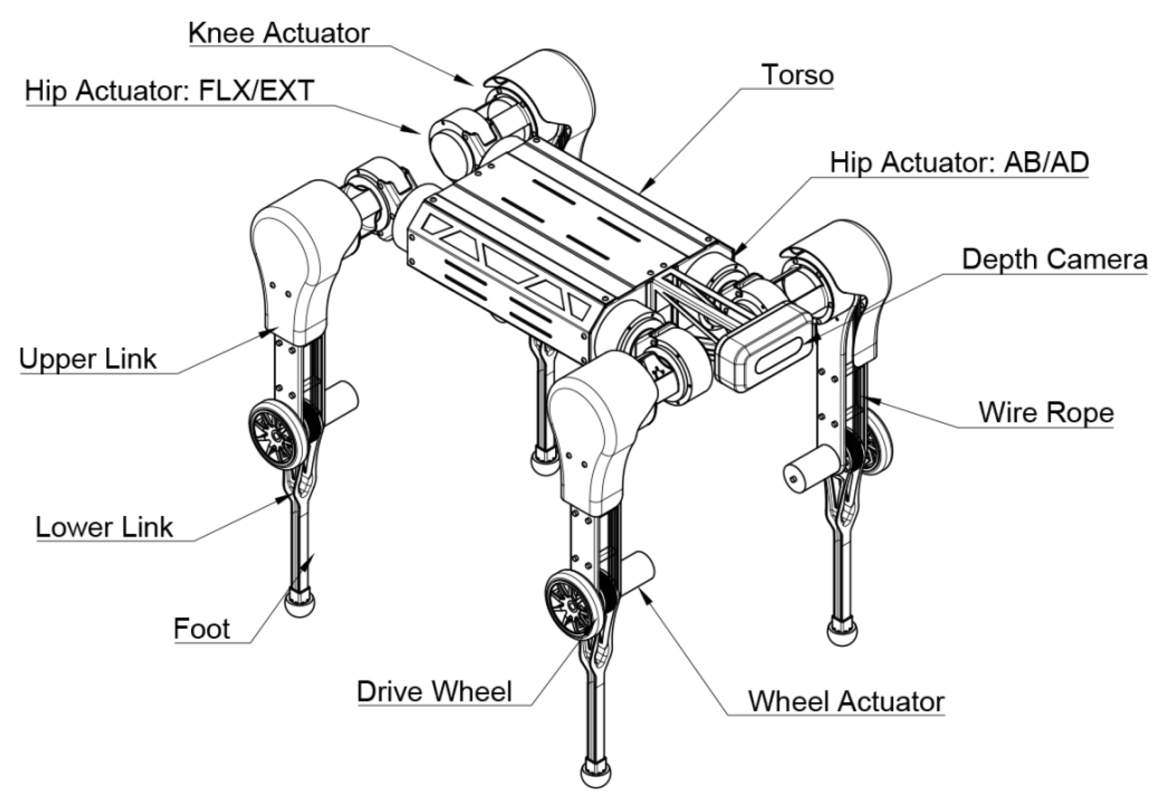
Applsci 12 09239 g001
Figure 2. The designed structure of the robot platform.
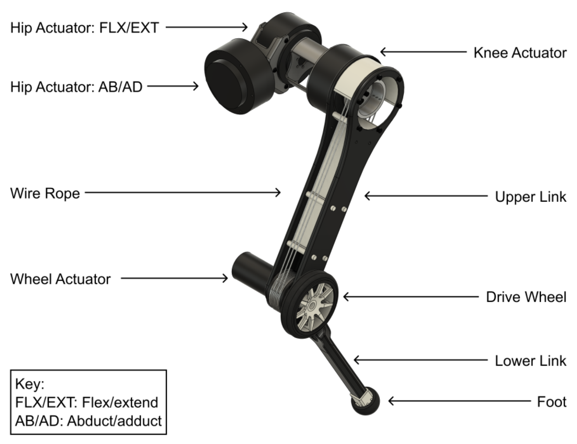
Applsci 12 09239 g002
Figure 3. The designed structure of a robot leg.
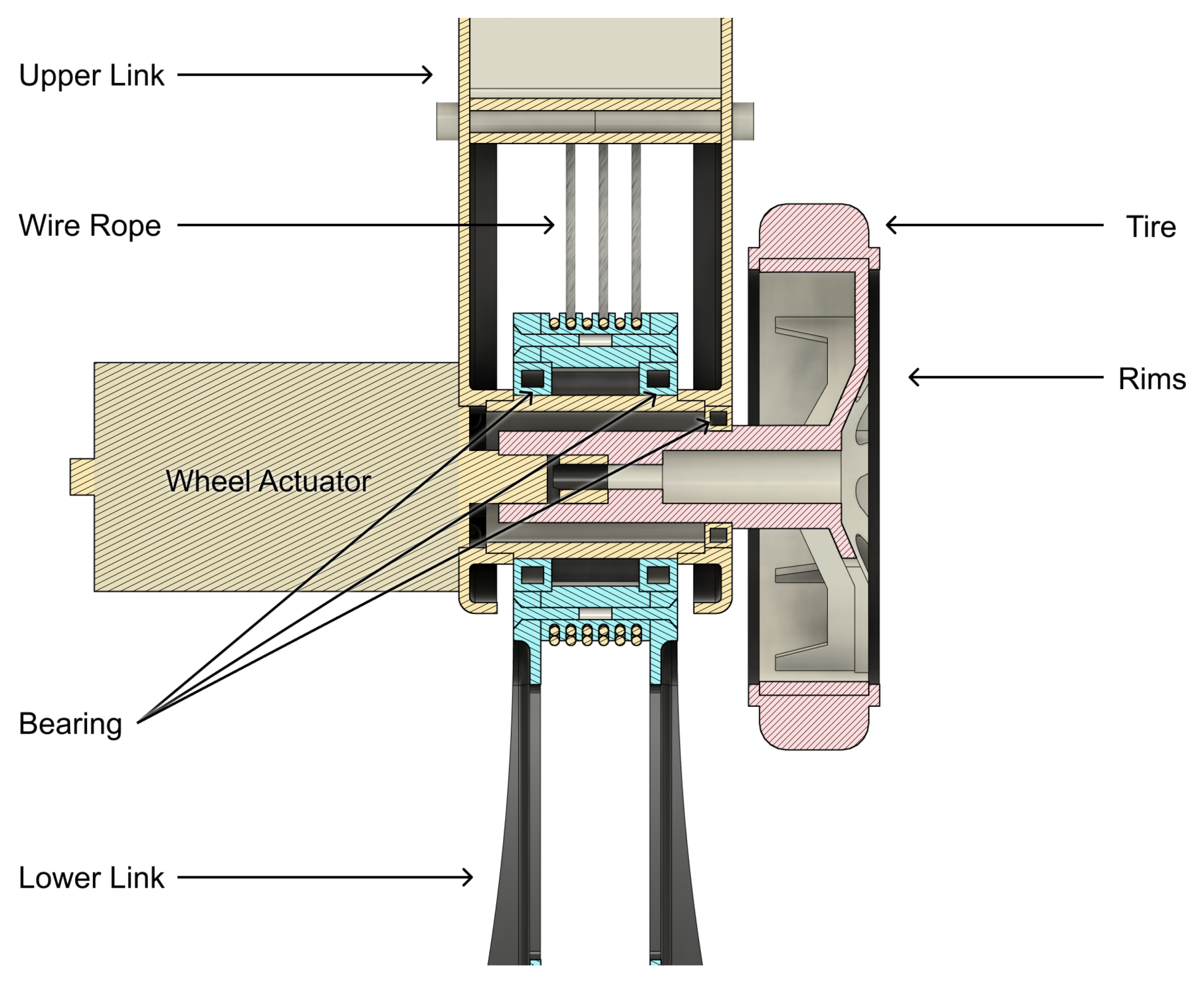
Applsci 12 09239 g003
Figure 4. The designed structure of the robot knee.
Applsci 12 09239 g004
Figure 5. The roped transmission structure. The radius does not change in the designed activities.
Applsci 12 09239 g005
Figure 6. Exploded view of the structure of each robot leg.
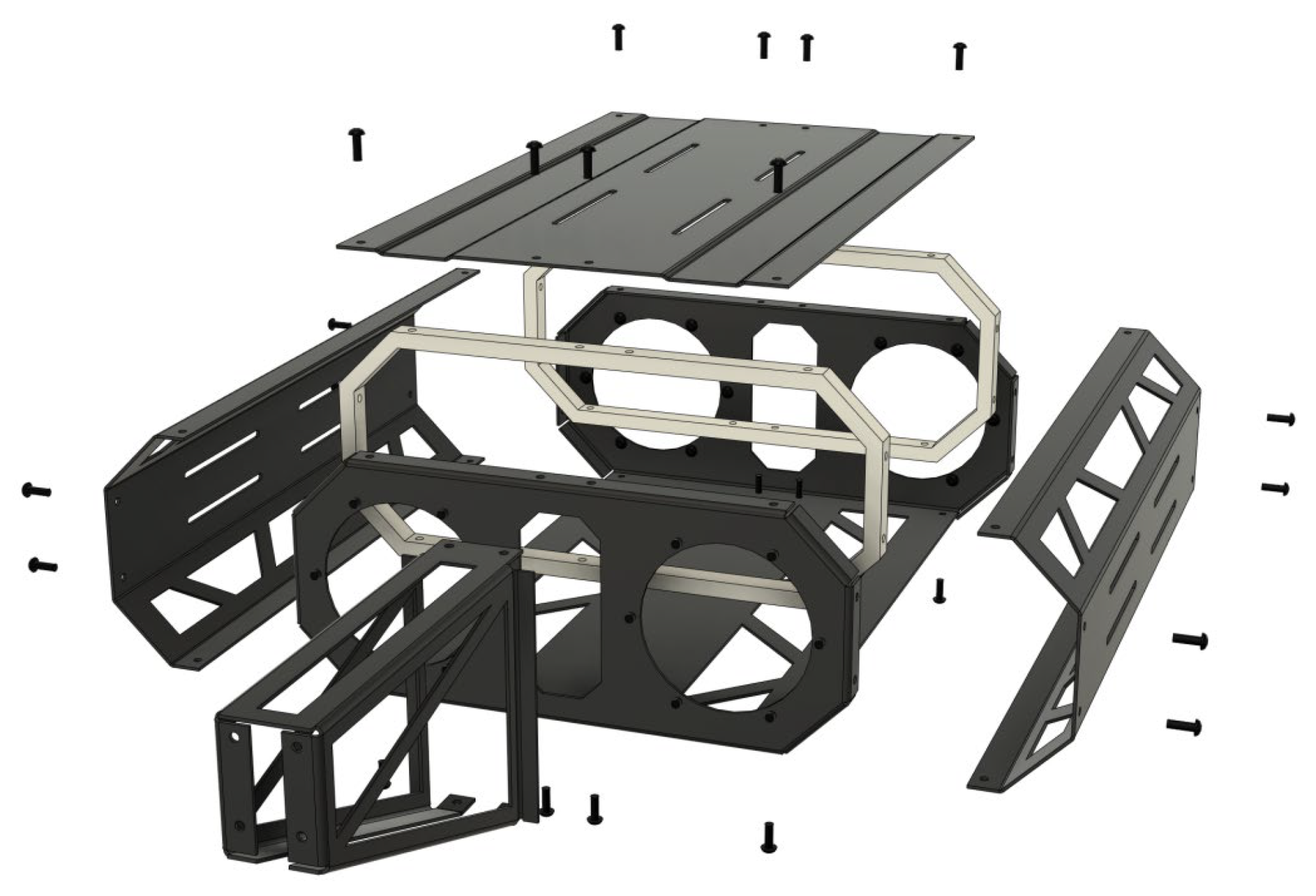
Applsci 12 09239 g006
Figure 7. Exploded view of the structure of the torso.
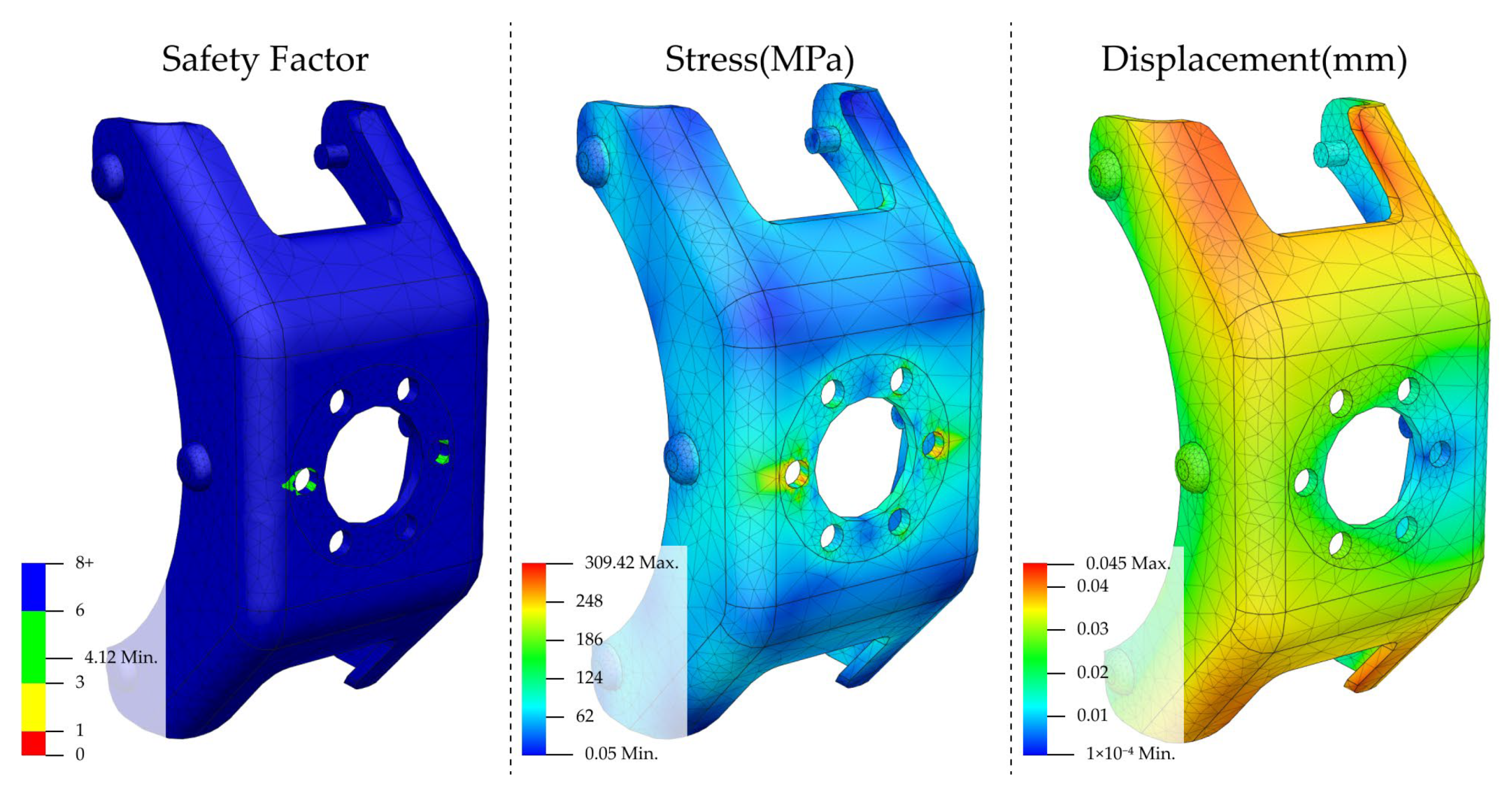
Applsci 12 09239 g007
Figure 8. Analysis of condition 1 for hip connector 1. From left to right are the safety factor, stress, and displacement.
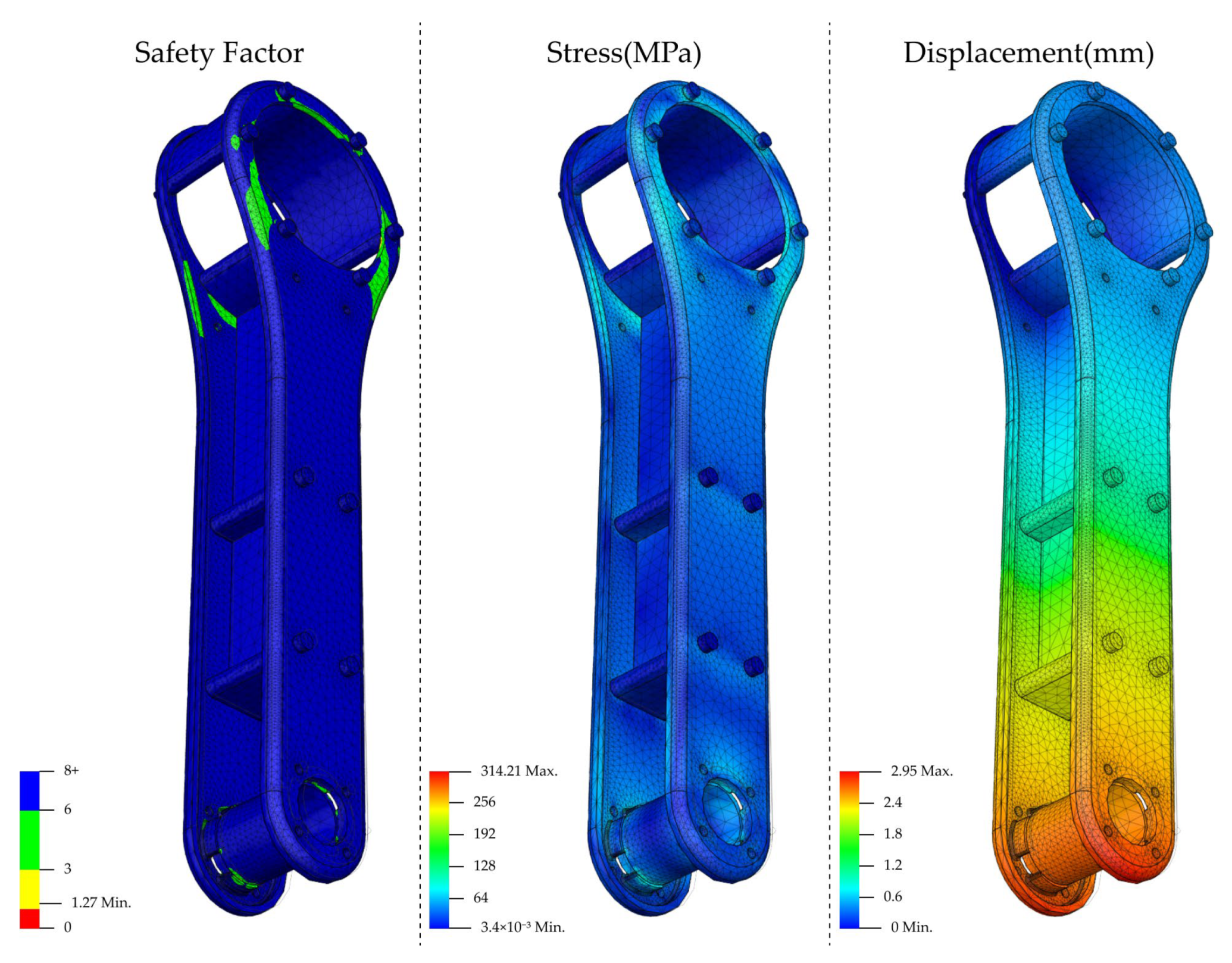
Applsci 12 09239 g008
Figure 9. Analysis of condition 2 for hip connector 1. From left to right are safety factor, stress, and displacement.
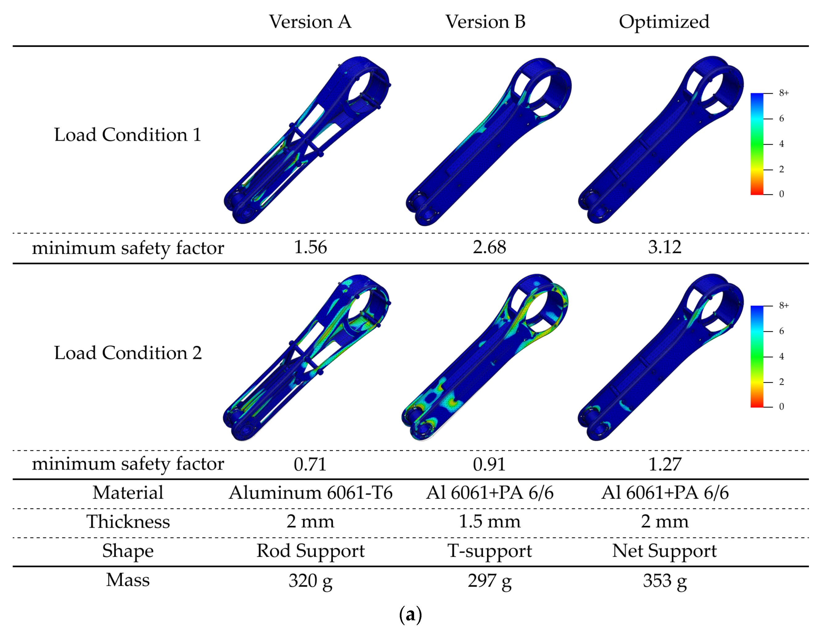
Applsci 12 09239 g009
Figure 10. Optimization process of hip connector 1. The part has a thickness limit, so the strength needs are met by changing the material.
Applsci 12 09239 g010
Figure 11. Analysis of condition 1 for hip connector 2. From left to right are safety factor, stress, and displacement.
Applsci 12 09239 g011
Figure 12. Analysis of condition 2 for hip connector 2. From left to right are safety factor, stress, and displacement.
Applsci 12 09239 g012
Figure 13. Optimization process of hip connector 2.
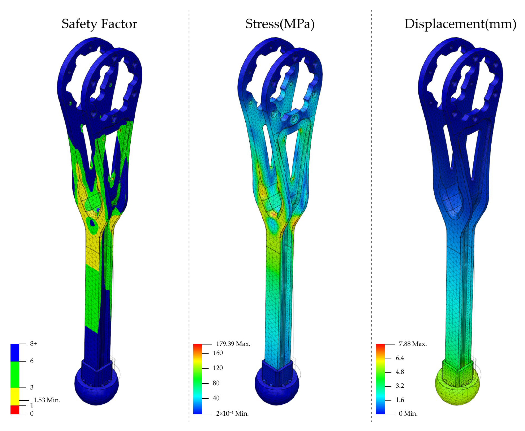
Applsci 12 09239 g013
Figure 14. Analysis of condition 1 for the upper link. From left to right are the safety factor, stress, and displacement.
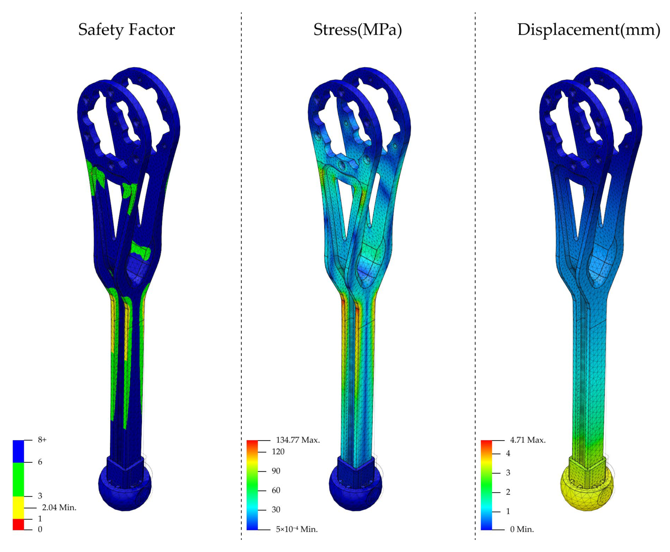
Applsci 12 09239 g014
Figure 15. Analysis of condition 2 for the upper link. From left to right are the safety factor, stress, and displacement.
Applsci 12 09239 g015
Figure 16. Optimization process for hip connector 2: (a) effect of different shapes on strength; (b) detailed display of different shapes.
Applsci 12 09239 g016aApplsci 12 09239 g016b
Figure 17. Analysis of condition 1 for the lower link. From left to right are safety factor, stress, and displacement.
Applsci 12 09239 g017
Figure 18. Analysis of condition 2 for lower link. From left to right are safety factor, stress, and displacement.
Applsci 12 09239 g018
Figure 19. Drive wheel analysis. From left to right are the safety factor, stress, and displacement.
Applsci 12 09239 g019
Figure 20. Torso shell analysis. From left to right are safety factor, stress, and displacement.
Applsci 12 09239 g020
Figure 21. The step circle of each move: (a) The process of a step can be divided into five individual time phases, and the robot can form a complete action by linear interpolation between six positions and poses; (b) when the robot ascends the stairs, it completes a step of the left hind foot, and the trajectory of the torso and the step foot.
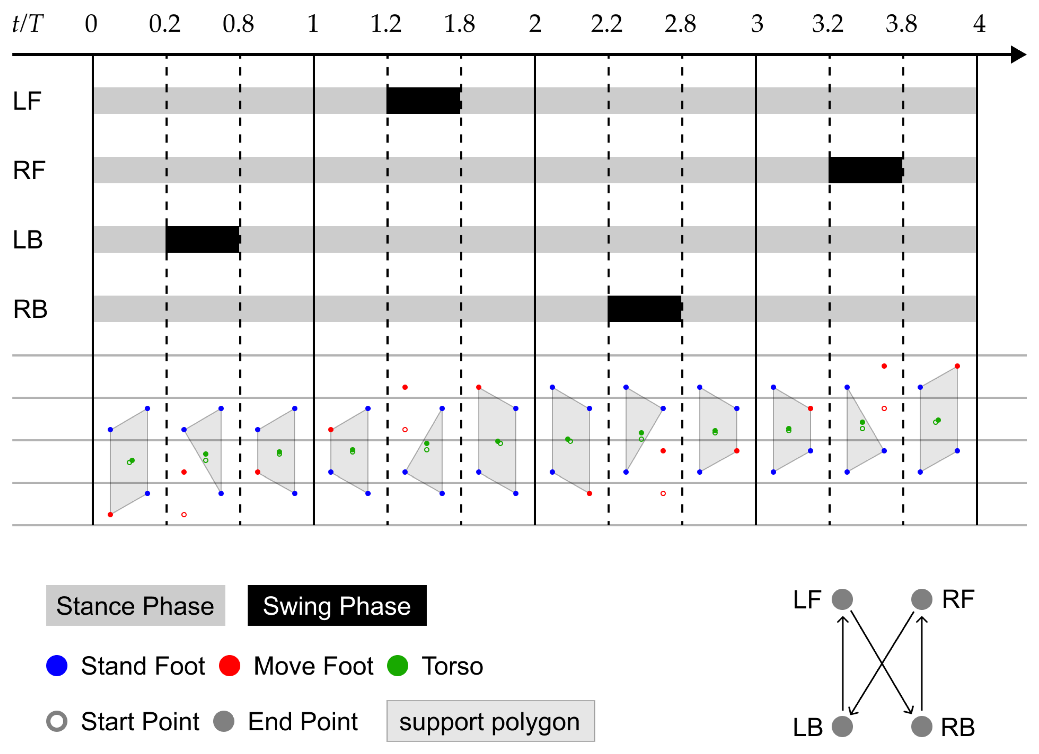
Applsci 12 09239 g021
Figure 22. Gait cycle. During the 4 T time, each of the four legs of the robot completes a step movement in sequence.
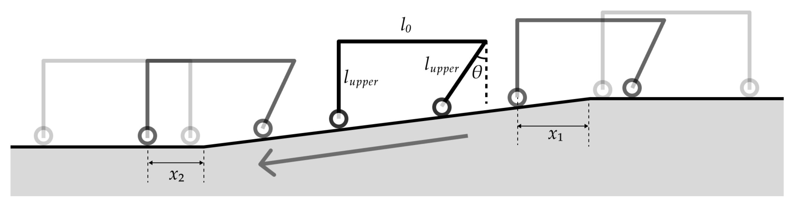
Applsci 12 09239 g022
Figure 23. Motion planning for downward movement; by adjusting θ , the torso can keep its horizontal pose.
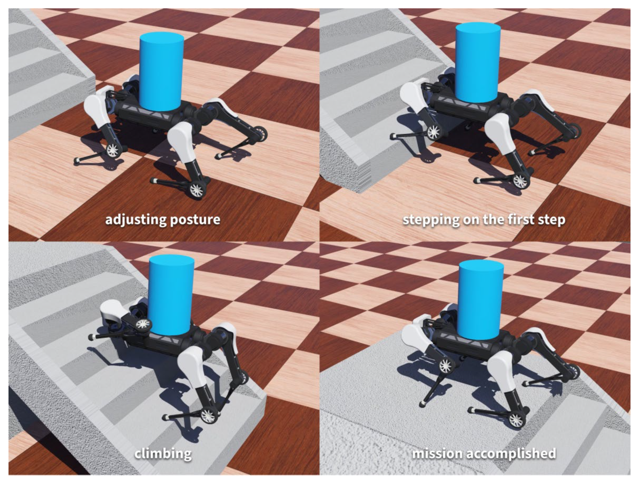
Applsci 12 09239 g023
Figure 24. Simulation task. At 16.940 s, the robot stepped on the first step; at 46.085 s, the robot fully landed on the platform.
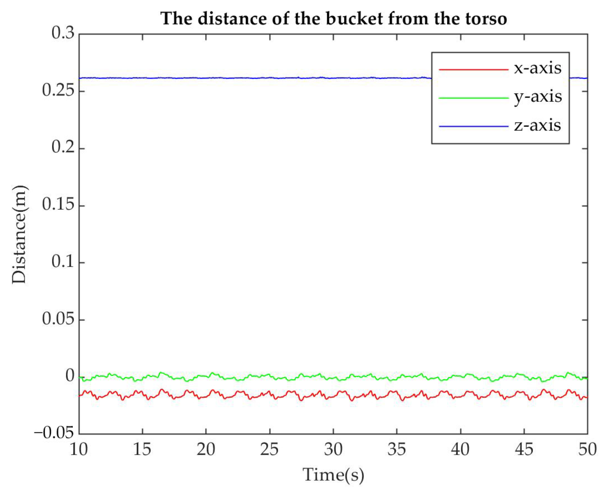
Applsci 12 09239 g024
Figure 25. Bucket position changes between 10 and 50 s. The bucket has periodic small movements in the y direction, nearly uniform linear movement in the x direction, and smooth movement in the z direction.
Applsci 12 09239 g025
Figure 26. Relative movement of the bucket and torso. In the case of the bucket being not fixed, only a slight slippage occurs above the robot.
Applsci 12 09239 g026
Figure 27. Joint torque of the left front leg. Most of the time, the output torque of the actuator is within the recommended range. When climbing the stairs, hip FLX/EXT actuator periodically outputs maximum torque for short periods of time.
Applsci 12 09239 g027
Table 1. Work scenes, force transmissions, and mobility features of relevant quadruped robots.
RobotWorking SceneForce Transmission Mobility Method
Kirin [17]Transport, Heavy dutyElectric ActuatorsLegs/Lifts
HyQ2Max [18]Universal, Heavy dutyHydraulic ActuatorsLegs
Swiss-Mile [19]Universal, Heavy dutyElectric Actuators/HybridWheels on feet/legs
ANYmal [20]Universal, Medium dutyElectric ActuatorsLegs
Mini cheetah [21]Swift, Universal, Light dutyE-ActuatorsLegs
Lywal [22]Transport, Medium dutyElectric Actuators/HybridWheels/Claws/Legs
OursAssistive, Medium dutyLow-Cost Actuators/Ligament Wired, Low costWheels on knees/legs
Table 2. Physical parameters of the robot.
ParameterSymbolValueUnits
Mass m b o d y 28kg
Torso inertia I x x 0.11kg·m2
I y y 0.28kg·m2
I z z 0.37kg·m2
Torso length l b o d y 0.69m
Torso width w b o d y 0.58m
Torso height h b o d y 0.75m
Leg link length l u p p e r ,   l l o w e r 0.3m
Foot diameter Φ f o o t 0.04m
Table 3. Actuator parameters.
ParameterValueUnits
Joint actuator mass0.85kg
Max joint torque120N·m
Max joint velocity6Rad/s
Wheel actuator mass0.37kg
Max wheel torque3N·m
Max wheel velocity50Rad/s
Table 4. Study materials.
MaterialYoung’s ModulusPoisson’s RatioYield Strength
Steel AISI 1045207 GPa0.331274 MPa
Aluminum 606168.9 GPa0.33275 MPa
Nylon 6/62.93 GPa0.3582.75 MPa
Rubber0.003 GPa0.4921 MPa
Table 5. Key gait parameters.
ParameterSymbol
Stride length l
Step height h
Rise r
Balance compensation w
Step time T
Table 6. Contact properties.
Material 1Material 2Coulomb FrictionBounce
DefaultDefault0.30.25
RubberDefault0.60.5
Publisher’s Note: MDPI stays neutral with regard to jurisdictional claims in published maps and institutional affiliations.

