Article

Target-Oriented High-Resolution and Wide-Swath Imaging with an Adaptive Receiving–Processing–Decision Feedback Framework

1
School of Information and Communication Engineering, University of Electronic Science and Technology of China, Chengdu 611731, China
2
School of Aeronautics and Astronautics, University of Electronic Science and Technology of China, Chengdu 611731, China
*
Author to whom correspondence should be addressed.
Appl. Sci. 2022, 12(17), 8922; https://doi.org/10.3390/app12178922
Submission received: 20 July 2022 / Revised: 2 September 2022 / Accepted: 3 September 2022 / Published: 5 September 2022
(This article belongs to the Special Issue Computational Sensing and Imaging)

Abstract

:
High-resolution and wide-swath (HRWS) synthetic aperture radar (SAR) is a promising technique for applications such as maritime surveillance. In the maritime environment, normally only a few targets such as ships are interested. However, before detecting them, considerable receiving resources and computation time are required to receive the echoes of the whole scene and process them to obtain imaging results. This is a heavy burden for online monitoring on platforms with limited resources. To address these issues, different from the concept of whole-scene-oriented imaging, we propose a target-oriented imaging concept, which is implemented by an adaptive receiving–processing–decision feedback framework with feedback connection. (1) To reduce receiving resource consumption, we propose a two-dimensional adaptive receiving module. It receives sub-band echoes of targets only through dechirping and subaperture decomposition in the range and azimuth directions, respectively. (2) To reduce computation time, we propose a target-oriented processing module. It processes subarea echoes of targets only through parallelly conducting inverse fast Fourier transform (IFFT) and back projection (BP) in the range and azimuth directions, respectively. (3) To allocate resources reasonably, we propose a decision module. It decides the necessary receiving window, bandwidth, and image resolution through constant false alarm rate (CFAR) detection. (4) To allocate resources adaptively, we connect three modules with a closed loop to enable feedback. This enables progressive target imaging and detection from rough to fine. Experimental results verify the feasibility of the proposed framework. Compared with the current one, for a typical scenario, at least 30% of the system’s resources and 99% of computation time are saved.

1. Introduction

High-resolution and wide-swath synthetic aperture radar (HRWS SAR) has drawn a lot of attention over the years [1,2,3,4,5]. The main reason is that it can overcome the minimum antenna area constraint and provide high-resolution images of more extensive areas compared with the traditional SAR [6,7]. For example, the German Aerospace Center (DRL) plans a mission called High-Resolution Wide-Swath to enhance the performance of the current SAR system, TerraSAR-X. The mission designs a 3 m resolution with 80 km swath coverage for the stripmap mode [8]. Compared with the current TerraSAR-X [9], a 30 km increment is obtained. These prominent advantages make it suitable for applications such as maritime transportation surveillance [8], military target indication [10,11,12], etc.
Compared with the traditional SAR, the system’s pulse repetition frequency (PRF) needs to be lower to receive echoes from the wide swath area. This may result in the undersampling problem in the azimuth direction, causing ghost images from Doppler ambiguity in the final imaging result [13]. To solve this problem, the HRWS SAR system is designed to deploy multiple receiving channels in the azimuth direction [14]. By receiving echo from multiple channels at the same time, using spatial sampling to replace it, equivalent sampling frequency thus increases multiple times, and undersampling is avoided. Due to these additional receiving channels, new imaging models need to be established, and corresponding imaging algorithms need to be studied. Researchers mainly studied these two aspects over the last decade [3,4,15,16,17,18,19,20,21,22], among which issues related to imaging such as multichannel signal reconstruction [13,15,16,17,18], amplitude/phase balancing, and motion error compensation [3,4,5,19,20] were studied the most. In the meantime, along with these developments, multiple new spaceborne and airborne SAR systems have been designed with HRWS imaging capability [2,8,21,22,23], which again shows its attractive practical value.
The previous methods follow the imaging framework in which the imaging result of the whole scene is needed first before detecting targets [24,25]. For some specific application fields, such as maritime surveillance, the online processing performance is limited due to the following two gaps left by previous approaches.
First, when the hardware resources are limited, the design of the imaging framework does not consider it. From the perspective of hardware receiving resources, high resolution means that a high sampling rate is required to sample echo signals with large bandwidth, and wide coverage means a large storage capacity to store echo signals of the whole scene. Although most of them provide little information, the system still needs to receive their echo signals, which increases the consumption of receiving resources.
Secondly, when the real-time requirement for software processing is high, the design of the imaging framework does not consider it. From the perspective of computation time, all echoes need to be processed to obtain the whole scene image, increasing computation time consumption.
To fill the two gaps, we need to design a new imaging framework related to hardware and software, and the focus should be on the consumption and allocation of resources. Thus, conceptually, we propose a new imaging concept to guide the design of the imaging framework. Unlike the existing whole-scene-oriented imaging framework, the concept is target-oriented: the system’s resource allocation is to serve the online target-detection task. Specifically, guided by the concept, we propose an adaptive receiving–processing–decision feedback framework from the aspects of hardware, software, and their combination. To be specific:
First, to reduce the consumption of receiving hardware resources, we propose a two-dimensional adaptive receiving module, which only receives echoes from targets. Specifically, it receives necessary bandwidth and time-width echoes from targets by dechirping and subaperture decomposition in the range and azimuth directions, respectively.
Second, to reduce the consumption of computation time, we propose a target-oriented processing module, which only processes the echoes from targets. Specifically, it only obtains the images of targets with a necessary resolution by parallel-streaming inverse fast Fourier transform (IFFT) and back projection (BP) in the range and azimuth directions, respectively.
Third, to allocate resources reasonably, we propose a decision module, which decides the parameters of the receiving and processing modules. Specifically, it determines the receiving window, the receiving aperture in the range and azimuth directions, and the processing bandwidth by constant false alarm rate (CFAR) detection to extract areas of targets.
Fourth, to allocate resources adaptively, we connect three modules in a closed loop to realize feedback. Specifically, it fulfills allocating resources adaptively by imaging and detecting targets progressively from coarse to fine.
The contributions of this work are summarized as follows.
  • A target-oriented imaging concept is proposed for HRWS SAR imaging. To the best of our knowledge, this is a first in the HRWS SAR imaging community.
  • An adaptive receiving–processing–decision feedback framework, aiming at specific application fields such as maritime surveillance, is proposed to fulfill the concept. We propose three modules (2D adaptive receiving module, target-oriented processing module, and decision module) with a closed-loop connection. The modules and the link are designed considering characteristics related to the application field, imaging scene, and the radar system.
  • The proposed framework simplifies the processing flow, providing a feasible end-to-end way for HRWS SAR online maritime surveillance to obtain the target detection results directly.
The feasibility of the proposed target-oriented imaging concept and the realization of the imaging framework is verified through numerical simulations. The system’s resources and computation time are significantly saved compared with the current framework. For a typical scenario, our framework saves at least 30% sampling resources, 33% storage resources, and 99% computation time.
The rest of this paper is organized as follows. Section 2 reviews the current imaging framework. Section 3 introduces the proposed imaging concept and its realization framework. Section 4 presents the experiments and the results. Conclusions are shown in Section 5.

2. Review

In this section, a brief review of the current imaging framework for HRWS SAR imaging is presented. Taking the most common type of HRWS SAR system design, for example, the azimuth multichannel SAR (AMC-SAR) [22,26], its imaging model is presented in Figure 1.
As shown in Figure 1, unlike the traditional SAR system, multiple receiving channels are deployed along the azimuth direction. Within each transmitting pulse, these receiving channels simultaneously receive echoes from the whole scene. Considering the transmitting signal as the linear frequency-modulated signal, the received signal of each channel for one point target can be expressed as
S r b t , η , i = A 0 r e c t t t 0 η T r exp j π K r t t 0 η 2 exp j 2 π f 0 t 0 η
where t is the range time, η is the azimuth time, i = 1 , 2 , , N is the channel index and N is the number of channels, A 0 is the target intensity, r e c t · is the range envelope function, t 0 η = 2 R 0 η / c is the target instantaneous range time delay, R 0 η is the target instantaneous slant range distance, c is the light speed, T r is the pulse width, K r is the frequency modulation rate of transmitting signal, and f 0 is the carrier frequency. For imaging in the range direction, matched filtering is conducted, and the imaging result in the range direction is
s r t , η , i = A 0 s i n c K r T r t t 0 η exp j 2 π f 0 t 0 η
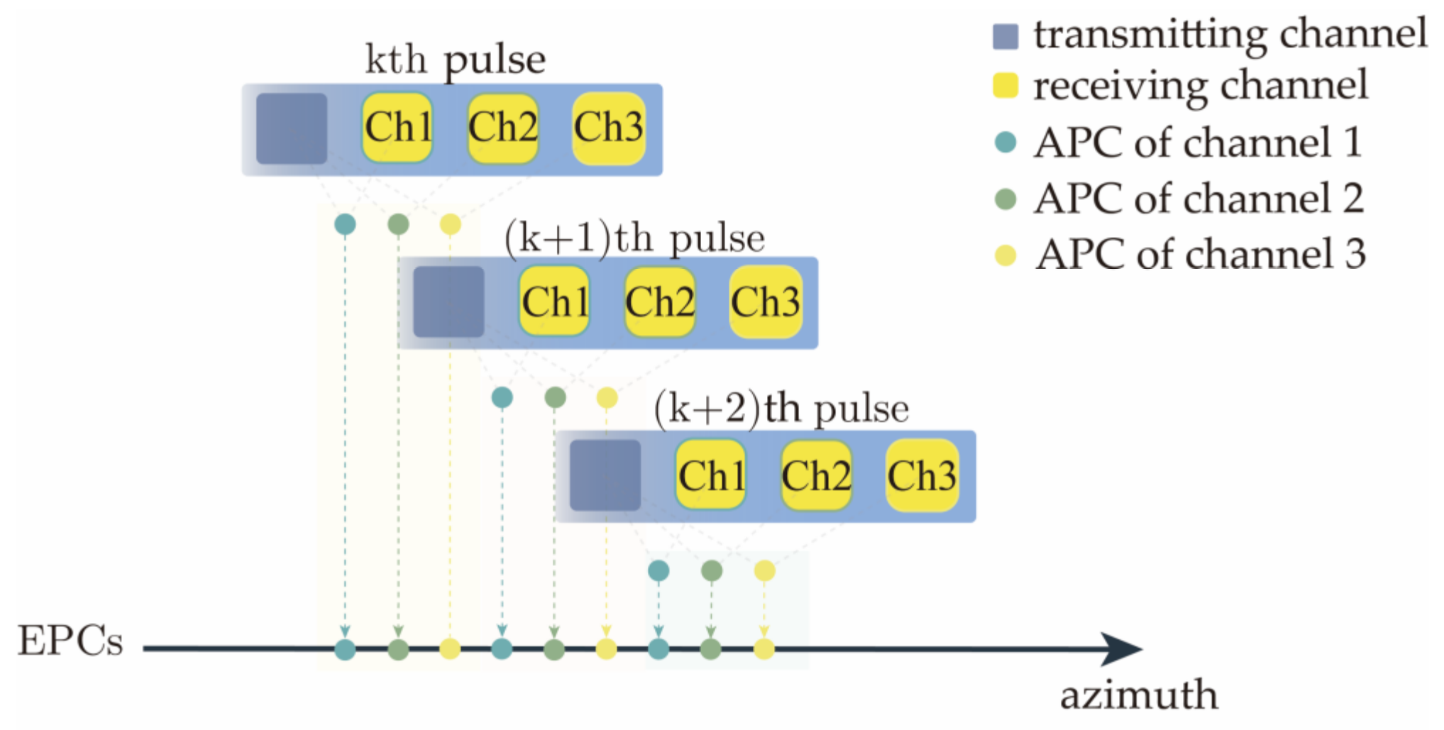
The next step is azimuth multichannel signal reconstruction. This step is the core step of AMC-SAR signal processing. This step allows for imaging results of all receiving channels in the range direction to be reorganized and combined into an equivalent result of traditional single-channel SAR [27]. As shown in Figure 2, the combined imaging result in the range direction is obtained through the rearranging of samples according to the azimuth time sequence and channel arrangement sequence. The antenna phase centers (APCs) of each channel are sorted into equivalent phase centers (EPCs) [28].
The rearranged result is
s r t , η = , s a r t , η k , s a r t , η k + 1 s a r t , η k = s r t , k   · PRT , 1 , s r t , k   · PRT , 2 , s r t , k   · PRT , 3 s a r t , η k + 1 = s r t , k + 1 · PRT , 1 , s r t , k + 1 · PRT , 2 , s r t , k + 1 · PRT , 3
where k is the pulse index and PRT is the pulse repetition period. After multichannel signal reconstruction, azimuth imaging methods for traditional SAR can be utilized, such as range-Doppler [29] and BP [30,31]. For wide-swath imaging, BP has some unique advantages. First, for a wide-swath scene, range-Doppler has the limitation of the imaging area’s size due to its approximated model of the range history, while this is not a problem for BP due to its accurate model [32]. Second, for online processing, range-Doppler has an online update limitation due to its need for the whole aperture, and this is not a problem for BP due to its ability of time-domain subaperture accumulation [31]. Third, for online processing, BP can be implemented in parallel through graphical processing units (GPU). Fourth, for platforms with maneuverability, BP can be implemented with a nonlinear trajectory [19]. Due these advantages, we prefer BP as the azimuth imaging method. Thus, the final imaging result after BP is
I m , n = T A s r t , η exp j 2 π f 0 t 0 η d η
where m and n are the image’s azimuth and range pixel index, respectively, and T A is the synthetic aperture time. The current imaging framework for HRWS imaging is summarized and illustrated in Figure 3.

3. Methodology

In the last section, we briefly review the current imaging framework for HRWS imaging. In this section, the methodology of the proposed target-oriented imaging concept and its realization framework are presented in detail.
From the current imaging framework in Figure 3, two core modules of receiving and processing form it. While it is a general framework for all kinds of imaging scenes, it may not be the most suitable one for applications such as maritime surveillance, especially for online surveillance on a resource-limited platform. We take an imaging result of a typical maritime scene, for example, as shown in Figure 4. It is from the LS-SSDD-v1. (Large-Scale SAR Ship Detection Dataset-v1.0, LS-SSDD-v1) dataset we released before [25].
From the figure, we can clearly see that most of the scene is water surface, and the interested targets of ships only occupy a relatively small part, revealing the strong sparsity of the scene. However, as shown in Section 2, echoes of the whole scene need to be received and processed. Then, for further surveillance, ship target detection is performed on the entire imaging result. As we explain in Section 1, this framework increases the burden of receiving resources and computation time, which is not favorable for online maritime surveillance.
With this observation, utilizing the strong sparsity of the scene, we propose a new target-oriented imaging concept and its realization framework, as shown in Figure 5.
To serve the need for online maritime surveillance, one key issue is the appropriate management of the resource budget. The first principle is to minimize unnecessary costs. Therefore, compared with the general imaging concept that is whole-scene-oriented, we propose this target-oriented one that guides the resource allocation to the targets and avoids the unnecessary resource allocation to the pure-water area. The second principle is to maximize necessary allocation. Therefore, compared with the general imaging framework with just two main modules (receiving and processing) as shown in Figure 3, we propose an adaptive feedback framework with an additional decision module and the feedback connection to dynamically allocate the resource.
As seen in Figure 5, the proposed framework consists of three basic modules, namely receiving, processing, and decision modules. They are connected in a closed-loop way to enable feedback. This idea is inspired by biological behavior, where animals perceive the surrounding environment and then adjust their behavior according to its information. Thus, from the perspective of perception, the first two modules collect and process to obtain information from the imaging scene, respectively. From the perspective of action, the last module and the feedback connection process the obtained information and then decide the system’s following response. Their details are presented in the following three subsections.

3.1. Two-Dimensional Adaptive Receiving Module

In this subsection, we introduce the first module in our proposed imaging framework, the 2D adaptive receiving module. From the perspective of hardware resource consumption, this module is designed to reduce the consumption of receiving resources.
In general, receiving resource consumption is mainly determined by two factors, which are sampling frequency and storage occupation. For the sampling frequency, according to the well-known Nyquist sampling theorem [33], it should be at least the bandwidth of the receiving echo. Thus, the requirement for the sampling device is expressed as
F s B r  
where F s is the sampling rate and B r is the signal bandwidth. For the storage occupation, it is determined by the sampling length and the sampling frequency, which is expressed as
D s F s T s  
where D s is the storage occupation and T s 
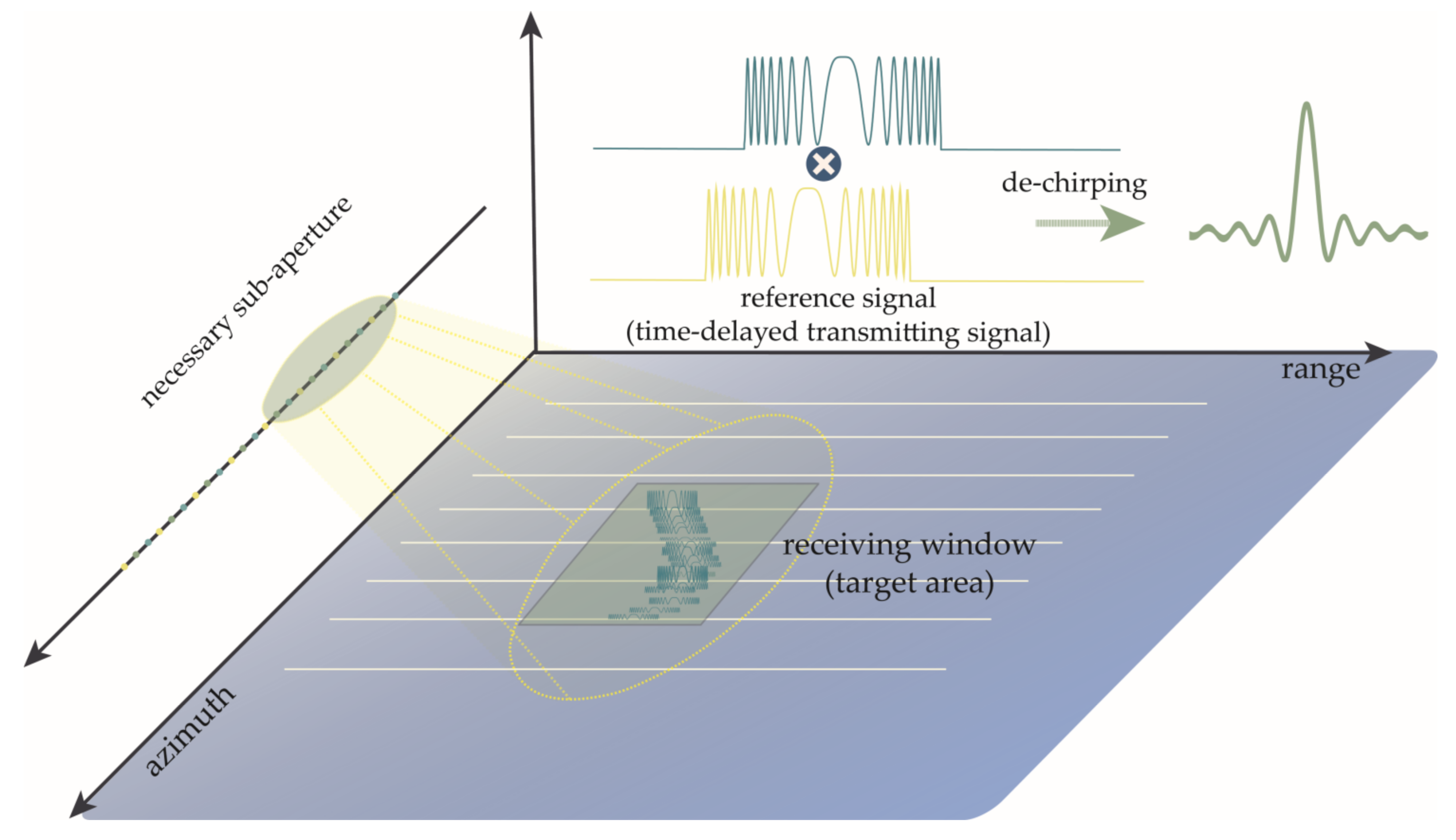
is the sampling time length. As seen from the above two formulas, to reduce the consumption of receiving resources, we need to reduce the sampling frequency and the sampling length. In our 2D adaptive receiving module, necessary bandwidth and time-length echoes from targets are received by dechirping and subaperture decomposition in the range and the azimuth direction, respectively, as illustrated in Figure 6.
Unlike the normal receiving in the range direction, which is received by mixing the echoes with the local oscillator, the module adapts dechirping by mixing them with the time-delayed transmitting signal. It can be expressed as
s r c t , η , i = A 0 r e c t t t 0 η T r exp j π K r t t 0 η 2 exp j 2 π f 0 t t 0 η s t t = r e c t t T r exp j π K r t 2 exp j 2 π f 0 t s r 2 t , η , i = s r c t , η , i s t t s r 2 t , η , i A 0 r e c t t t 0 η T r exp j 2 π K r t 0 η t exp j 2 π f 0 t 0 η
where is the conjugate operator. This formula shows that for a point target, its echo becomes a single-frequency signal, and the frequency is related to its slant range. Compared with the signal form in Formula (1), the bandwidth is reduced to zero. In practice, for a typical target such as a ship, it cannot be taken as a point target but as a distributed target, as shown in Figure 7.
For a distributed target, the dechirped echo can be expressed as
s r 2 t , η , i = l = 1 N T A l r e c t t t 0 l η T r exp j 2 π K r t 0 l η t exp j 2 π f 0 t 0 l η
where l = 1 , 2 , , N T is the target point index and N T is the number of points, A l is the intensity of the l   th point of the target, and t 0 l η is the instantaneous range time delay of the l   th point of the target. From this formula, we can see that its echo consists of multiple single-frequency signals for a distributed target, and its bandwidth is determined by the size of the target as follows:
B = K r W η  
where W η = m a x t 0 l η min t 0 l η is the time length of the target echo in the range direction. As the maximum length equals the receiving window’s length, the largest bandwidth is B m a x = K r T R . In general, the size of the ship does not exceed the order of 100 m, corresponding to the order of 1 μ s time length. In comparison with the length of the receiving window, the order of 10 μ s , it is much less. Benefitting from this, the needed sampling frequency is reduced a lot. In other words, because we only receive echoes from targets by dechirping, the receiving module only needs to bear the resource consumption of the necessary sub-band and partial-time-length echoes rather than the consumption of the full-bandwidth and full-time-length echoes from the whole scene.
The next step is to receive in the azimuth direction. In recent years, GPU has widely shown its strong calculation performance through thousands of parallel threads, which makes it suitable for imaging algorithms such as BP [31]. To facilitate the following signal processing, the module adapts parallel streaming subaperture decomposition receiving in the azimuth direction.
Since only the targets are to be imaged, instead of the whole aperture for the entire scene to be received, only a group of the targets’ subapertures is received individually. For each subaperture received, to avoid massive memory costs, the receiving storage framework is streaming architecture.
For CUDA device computation, the parallel computation is executed by thousands of threads running concurrently. For each thread, a pixel in the image is uniquely related to it, along with the pixel’s corresponding data in a different azimuth time. In the streaming architecture, instead of relating to the whole aperture of the imaging scene, the thread corresponds to its own aperture. A circular aperture buffer is used during the azimuth receiving phase, and each received echo of the target stream into the buffer by chronological order. Threads form into an image buffer, which is after the aperture buffer and stores and accumulates the processing results of the aperture buffer. Further, the massive storage device follows the image buffer to store the final imaging result. This three-level receiving structure is illustrated in Figure 8.
The sizes of the two buffers are determined by the aperture’s length, the size of targets, and the pixel interval. For the aperture buffer, its size is calculated as
N e a z = L a + W a g v PRT N
N e r g = T r F s N i n t e r p
where L a is the synthetic aperture length, v is the flight speed, W a g is the target size in the azimuth direction, N i n t e r p is the interpolation ratio in the range direction, and is the round up operator. For the image buffer, its size is calculated as
N i a z = W a g d a z
N i r g = W r g d r g
where d a z is the image pixel size in the azimuth direction, d r g is the image pixel size in the range direction, and W r g is the target size in the range direction.
The above receiving process is related to the target’s position and size. Thus, the receiving window’s position and size are adaptively changed according to the environment. Moreover, the azimuth receiving aperture’s length is also related to the necessary azimuth image resolution for target detection. It is adaptively changed from short to long according to the decision module’s feedback.
At the end of this subsection, we conclude by summarizing the receiving hardware resource consumption of the proposed receiving module, as presented in Table 1. The comparison with the current receiving module is also included.
In Table 1, c 1 is the oversampling ratio; c 2 = 2 N i n t e r p / c ; c 3 = N / v . W r s and W a s are the range length and the azimuth length of the whole scene, respectively. α 1 is the relative ratio of target’s length vs. the whole scene’s length in the range direction. α 2 and β are the relative ratios of receiving windows’ or subaperture’s length vs. the whole scene’s length in the range direction and the azimuth direction, respectively.
In summary, utilizing the sparsity of the entire scene and the relatively small size of targets, this receiving module reduces both the sampling frequency and storage occupation a lot, according to Table 1. In general, the sparser the scene is, the more relative reduced proportion we can obtain.

3.2. Target-Oriented Processing Module

In this subsection, we introduce the second module in our proposed imaging framework, the target-oriented processing module. From the perspective of software resource consumption, this module is designed to reduce the consumption of computation time.
In general, the resource consumption of computation time is mainly determined by time and spatial complexities. To reduce them, we first reduce the data amount to be processed, by means of target-oriented processing that only handles the echoes from targets; secondly, we execute the computation process in a parallel streaming way through a GPU device.
First, as depicted in Formula (8), the received echoes from a target consist of multiple single-frequency signals. Their frequencies are linearly related to the range distance of the points. Thus, imaging in the range direction is conducted through IFFT, which can be expressed as
s r t , η , i = l = 1 N T A l s i n c K r T r t t 0 l η exp j 2 π f 0 t 0 l η
We can see from the result that multiple s i n c function peaks exist, and their peak locations correspond to the positions of the target points. The mainlobe width of these s i n c functions is inversely proportional to the transmitting signal bandwidth. In other words, through dechirping receiving and IFFT processing, the resolution of the imaging result in the range direction is the same as the current match-filtering processing.
The designed process contains one multiplication operation and one fast Fourier transform (FFT) operation. As for the matched-filtering way, it includes one operation of FFT to transform echoes in the time domain into the frequency domain, one multiplication operation with the matched filter, and one operation of IFFT to transform it back into the time domain. Thus, the designed processing saves one operation of FFT.
Second, as depicted in (14), one phase term that contains the range histories exists. For imaging in the azimuth direction, this phase term needs to be compensated via parallel streaming BP. As presented earlier in the last subsection, we use the GPU device to conduct streaming BP, which means that one range imaging result is obtained in one azimuth moment; it is streamed into one column of aperture buffer after interpolation via zero-padding in the frequency domain. Following this step, every thread corresponding to every pixel in the 2D image traces the corresponding position of response in the aperture buffer at this moment, and takes it out with the phase compensation term to coherently accumulate. Once the necessary resolution is obtained, the image buffer streams out the current 2D imaging result to the massive storage device, as shown in Figure 9.
Specifically, every thread’s calculation includes steps as follows.
1.
Calculate the time delay in the range direction.
Given the corresponding image pixel’s position, the time delay at every moment in the azimuth direction is calculated as
t 0 p η = 2 P x , y P e p c η 2 c
where P e p c η is the EPC position of the system at azimuth time η ; P x , y is the pixel’s position x , y in the imaging plane.
2.
Calculate the position of response in the aperture buffer.
Given the time delay calculated before, the corresponding position in the aperture buffer is calculated as
I D η = r o u n d t 0 p η T d e l a y + 1 2 T r T r
where T d e l a y is the time delay of the receiving window and r o u n d is the rounding operator.
3.
Compensate the phase term.
Given the time delay calculated before, the corresponding compensated response is calculated as
t e m p = s r t , η , i exp j 2 π f 0 t 0 p η
4.
Coherent accumulation.
Given the phase compensated response, the image pixel’s value is coherently accumulated with the new response as
I x , y I x , y + t e m p
The above calculations are repeated until the necessary resolution in the azimuth direction is achieved.
The streaming BP computation complexity is determined by the number of pixels in the 2D image—the size of the target, in other words—and the length of aperture to be accumulated. For a single round of the above calculation steps, one operation of multiplication and one operation of addition are conducted.
At the end of this subsection, we conclude it by summarizing the computation time resource consumption of the proposed target-oriented processing module, as presented in Table 2. The comparison with the current processing module is also included.
In Table 2, N a is the number of azimuth sampling points for the whole scene. N x and N y are the number of image pixels in the range and azimuth direction, respectively. β is the target-oriented ratio of necessary azimuth resolution vs. full azimuth resolution that is no more than 1; N r l is the number of sampling points in the range direction. N r l is the number after interpolation.
Similarly, with the help of the sparsity of the scene, the small size of targets, and the GPU device, this processing module reduces the computation time consumption a lot, according to Table 2. In addition, considering the need for target detection, the required resolution may be less than the maximum available resolution. Thus, azimuth accumulation time is saved.

3.3. Decision Module and Feedback Connection

In this subsection, we introduce the last module in our proposed imaging framework. Moreover, the modules’ feedback connections are also introduced, and they are designed to adjust the resource allocation dynamically.
As the system’s resources are limited, the principle of adjusting is to allocate them as reasonably and adaptive as possible. To allocate them more reasonably, the module adaptively decides the receiving module’s receiving window and aperture in the two directions so that resources are spent only on targets. To allocate them more adaptively, the module adaptively decides the necessary resolution of the image.
Specifically, the module uses CFAR to extract targets’ information, including their position and size. CFAR is a local detector to detect targets with an adaptive threshold [34]. For a single target’s pixel under detection, its surrounding clutter and noise pixels are used to calculate the corresponding threshold as
T = ρ N c m = 1 N c x m
where x m is the amplitude of clutter and noise pixel in the image, m is the pixel index, N c is the number of pixels, and ρ is the constant related to false alarm probability. To avoid the miscalculation with the target’s pixels being mixed in, guard pixels are set adjacent to the pixel under detection, as shown in Figure 10.
Meanwhile, the module uses image entropy [19] to decide the necessary resolution in the azimuth resolution. The image entropy is calculated as follows:
H = I x , y 2 S · l n S I x , y 2 S = I x , y 2
where I x , y is the amplitude of pixel x , y in the image. The entropy is to measure the randomness of the image statistically. In the SAR imaging community, it is usually used to indicate the degree of image focusing [19]. Normally, the more the image is focused, the lower the entropy is. In another information theory perspective, entropy indicates the amount of uncertainty. For random parts in the image—the clutter and noise—it has higher entropy than the targets’. When the resolution is low, the entropy difference between the part of targets and the part of the clutter and noise is not significant. As the resolution is increased, the difference increases, which is beneficial for target detection.
Initially, the target entropy is decreased rapidly. As target details are gradually revealed, the decreasing rate of entropy becomes low, as shown in Figure 11. Based on this, the module decides that the necessary resolution is achieved when the relative rate of change is lower than a threshold.
Finally, we introduce a feedback connection. The proposed receiving, processing, and decision modules are connected through this feedback connection so that the decision module can adapt to other modules’ parameters. The receiving window and subaperture length related to the positions of targets are fed back through this connection. For a single target, initially, the module sets the receiving aperture short in the azimuth direction. Then, it is gradually increased so that the imaging result of the target is progressively obtained from coarse to fine when the decision module decides that the necessary resolution is achieved. The decision is fed back through this connection to stop the resource allocation for this target.

4. Numerical Simulations

In this section, to verify the feasibility of the proposed target-oriented imaging principle and the realization framework, we conduct numerical simulations on both the simple point-like targets and the typical extended scene, highlighting the performance of our work. All the relevant parameters are shown in Table 3.

4.1. Point-like Target Simulation

As shown in Figure 12, 11 points with equal energy are set with equal spacing of 5 m in the range direction. These points cover a width of 50 m in total. In addition, these points are surrounded by Gaussian noise to simulate the pure-water environment. The signal-to-noise ratio (SNR) is set as 0 dB for the original echoes. In all, the whole scene covers 10 km width in the range direction, and the reference receiving window covers the same width of 3 km as the transmitting signal.
The results are shown in Figure 13. The first row of the figure presents the results corresponding to the current framework; in the second row, our results are presented. This simulation is to verify the feasibility of the framework in the range direction. Thus, only the imaging results in the range direction are presented. The situation in the azimuth direction is given in the next simulation. The light green rectangles in the left two columns of the figure are to indicate the area of targets. The first column includes the imaging results of the whole scene, the second column consists of the enlarged images of the target, and the last column contains the interpolated images of the point located at the center to measure the resolution metric. For visual comparison, the results of the two frameworks are interpolated to the same length.
From the comparison between Figure 13a,d, we can see that under both frameworks, the echoes are well-received and processed. All 11 points are located at their positions, clearly visible and distinguishable. From the perspective of receiving resource consumption, although the whole scene covers 10 km width, the area of targets is only 50 m long, indicating the strong sparsity of the scene, which is around only 0.5%. However, following the current framework, the whole scene’s echoes are received. The oversampling ratio is 1.2, and the resulting sampling frequency is 180 MHz. Thus, in total, 12,000 sampling points are received and stored. Meanwhile, for the proposed framework, as seen in Figure 13d, only echoes of 3 km width are received and processed, and the adequate bandwidth corresponding to the area of targets is 2.5 MHz. Using the same oversampling ratio, the resulting sampling frequency is 3 MHz, only around 1.7% of the current one; and the number of sampling points is 60, which is only 0.5% of the current one.
To validate the resolution performance, as shown in Figure 13c,f, we choose the center point to calculate its resolution (3 dB mainlobe width), and the results are 0.961 m and 0.928 m, respectively. This indicates that the proposed framework can still obtain the same resolution result, even with much less resource consumption. Moreover, the SNR is increased by around 30 dB, the as same as the current framework. This indicates that the proposed framework does not lose the processing gain.
Next, we rearrange these 11 points along the azimuth direction to verify the proposed framework’s performance in the azimuth direction. The simulated situation is shown in Figure 14. In the figure, Figure 14a is the whole scene’s image of 10 km in width, and the targets are centered at 5 km with 5 m equal spacing. In Figure 14b, the area of targets is enlarged. In addition, as in the last simulation, the Gaussian noise is added around the targets with 0 dB SNR condition.
The results are shown in Figure 15. The first row of the figure presents the results corresponding to the current framework; and in the second row, the results of ours are presented. This simulation is to verify the feasibility of the framework in the azimuth direction. Thus, only the imaging result in the azimuth direction is presented. The light green rectangles in the left two columns of the figure indicate the area of targets. The first column includes the imaging results of the whole scene, the second column consists of the enlarged images of the target, and the last column contains the interpolated images of the point located at the center to measure the resolution metric. For the sake of visual comparison, the results of the two frameworks are interpolated to the same length.
From the comparison between Figure 15a,d, we can see that the echoes in the azimuth direction are well-received and processed under both frameworks. Those 11 points form 11 peaks that can be clearly distinguished at their corresponding locations. Regarding the cost of receiving resources, according to the detection result, as shown in Figure 15e, the receiving and processing area is set as 150 m width centered at the target area, which is only 1.5% of the whole scene. On the contrary, following the current framework, the entire scene’s echoes are received, resulting in 125,000 sampling points being received and stored. Meanwhile, for the proposed framework, the number of sampling points 6050, which is only around 4.84% of the current one.
To validate the resolution performance, as shown in Figure 15c,f, we choose the center point to calculate its resolution (3 dB mainlobe width), and the results are 0.924 m and 1.4312 m, respectively. Different from the situation in the last simulation, which indicates the role of the decision module and feedback connection in the proposed framework. During the accumulation phase of azimuth processing, 11 points are clearly visible and distinguishable when the resolution achieves 1.4312 m, and the entropy of the imaging result, which indicates the information it can provide, is slowly varying. The decision module decides that the imaging result of the target is already suitable for the application and then stops the receiving and processing resource allocation on this target through feedback.
At the end of this subsection, we conclude the performance of our framework in the numerical simulations in Table 4, which shows that at least 90 % consumption of receiving resources is saved.

4.2. Typical Extended Scene Simulation

To further validate the proposed framework’s performance faced with the situation of more realistic scene, we carry out a typical extended scene simulation. One SAR image is taken as the radar cross section for simulation. The whole scene covers an area of 1000   m   ×   5000   m , where around 95.3 % are areas of pure-seawater surface and the rest of them are ship targets. The simulation parameters are the same as in the Table 3.
Our framework is designed not only from the perspective of software (simply reducing the computation time) but also from the perspective of the imaging concept, the hardware, and the hardware–software feedback, to better reveal the advantages that it can bring. For this extended scene simulation, we additionally compare it with another similar framework with Cartesian fast-factorized back projection (CFBP) [35].
Figure 16a shows the result of the current imaging framework. Figure 16b,c show the results of the framework with CFBP and the proposed imaging framework. Compared with the results of the current imaging framework and the framework with CFBP, our framework uses the system’s resources just on the targets’ areas instead of on the water area that provides litter information. Second, our result presents target-oriented variable resolutions in the azimuth direction instead of constant full resolution. Visually, although only part of the azimuth aperture’s data are accumulated, all the ships in the result look almost the same as the full-resolution results. Specifically, the effective aperture length for each ship, from the left to the right, is only 0.4, 0.42, 0.54, and 0.65, respectively, verifying the adaptive ability of our framework.
In addition, besides the traditional imaging result that can be obtained, as shown in Figure 17, the detection result can also be obtained through our framework. This provides an end-to-end way for maritime surveillance that simplifies the current procedures.
At the end of this subsection, we conclude the performance of our framework in the numerical simulations in Table 5, which indicates that for this typical scenario, at least 30% consumption of receiving resources and 99% consumption of computation time are saved.
In contrast, the CFBP’s result only saves 67.7% consumption of computation time, less than ours; and there is no consumption of receiving resources reduced. This is because the design of CFBP’s framework has not fully considered either the features of the HRWS SAR system or the features of the maritime surveillance application. In addition, it is still whole-scene-oriented, without the adaptive hardware receiving and feedback.
The ships are all located in the same area that the minimum receiving window and aperture in the two directions can cover. In the range direction, the ships are spread out in the receiving window, which makes the relative sampling bandwidth reduction less than the last simulation, and the scene’s width is half of the last one. Thus, the relative reduced proportion of receiving resources in the range direction is less. The situation is the same in the azimuth direction. However, the processing computation time is still reduced quite a lot (99.1%), because only the areas of ships are imaged and only around 50% of the aperture data are accumulated on average.

5. Conclusions

In this paper, a new target-oriented imaging concept for HRWS SAR imaging is proposed, including the realization framework. For applications such as maritime surveillance, we utilize the strong sparsity of the imaging scene to design the imaging framework, which aims to reduce the consumption of receiving resources and computation time for online surveillance.
The proposed adaptive receiving–processing–decision framework with feedback connection is inspired by the recent cognitive radar concept [35]. Thus, besides reducing unnecessary resource costs in the area with little information, we adaptively adjust the allocation of resources according to the perception result through the proposed decision module in the framework. Then, from the perspectives of hardware, we design a 2D receiving module to reduce the consumption from the receiving hardware system in terms of sampling frequency and sampling length; from the perspectives of software, the target-oriented processing module is proposed to reduce the computation time from processing in terms of both effective imaging area and imaging resolution. The concept and the framework are verified through numerical simulations, showing promising performance on both consumption reduction of receiving resources and computation time.
Currently, this paper conducts preliminary study about this concept and framework. More complex scenes are needed to consider. The resource allocation and dynamic schedule related to the GPU device both need to be studied further. Furthermore, for more efficient decisions to be fed back, target-detection methods utilizing deep learning techniques may be integrated into this framework [25,36].

Author Contributions

Conceptualization, X.Z. (Xiaoling Zhang); methodology, X.Z. (Xu Zhan); software, W.Z.; validation, Y.X.; form analysis, J.S.; investigation, S.W.; resources, T.Z. All authors have read and agreed to the published version of the manuscript.

Funding

This research was funded by National Natural Science Foundation of China, grant number 61571099. And the APC was funded by National Natural Science Foundation of China, grant number 61571099.

Institutional Review Board Statement

Not applicable.

Informed Consent Statement

Not applicable.

Conflicts of Interest

The authors declare no conflict of interest.

References

  1. Guo, X.; Gao, Y.; Liu, X. Azimuth-Variant Phase Error Calibration Technique for Multichannel SAR Systems. IEEE Geosci. Remote Sens. Lett. 2017, 14, 1383–1387. [Google Scholar] [CrossRef]
  2. Jansen, R.W.; Raj, R.G.; Rosenberg, L.; Sletten, M.A. Practical Multichannel SAR Imaging in the Maritime Environment. IEEE Trans. Geosci. Remote Sens. 2018, 56, 4025–4036. [Google Scholar] [CrossRef]
  3. Zhou, Y.; Wang, R.; Deng, Y.; Yu, W.; Fan, H.; Liang, D.; Zhao, Q. A Novel Approach to Doppler Centroid and Channel Errors Estimation in Azimuth Multi-Channel SAR. IEEE Trans. Geosci. Remote Sens. 2019, 57, 8430–8444. [Google Scholar] [CrossRef]
  4. Shang, M.; Qiu, X.; Han, B.; Yang, J.; Zhong, L.; Ding, C.; Hu, Y. The Space-Time Variation of Phase Imbalance for GF-3 Azimuth Multichannel Mode. IEEE J. Sel. Top. Appl. Earth Obs. Remote Sens. 2020, 13, 4774–4788. [Google Scholar] [CrossRef]
  5. Huang, H.; Huang, P.; Liu, X.; Xia, X.-G.; Deng, Y.; Fan, H.; Liao, G. A Novel Channel Errors Calibration Algorithm for Multichannel High-Resolution and Wide-Swath SAR Imaging. IEEE Trans. Geosci. Remote Sens. 2022, 60, 5201619. [Google Scholar] [CrossRef]
  6. Zhang, S.; Xing, M.; Xia, X.; Zhang, L.; Guo, R.; Liao, Y.; Bao, Z. Multichannel HRWS SAR Imaging Based on Range-Variant Channel Calibration and Multi-Doppler-Direction Restriction Ambiguity Suppression. IEEE Trans. Geosci. Remote Sens. 2014, 52, 4306–4327. [Google Scholar] [CrossRef]
  7. Krieger, G. MIMO-SAR: Opportunities and Pitfalls. IEEE Trans. Geosci. Remote Sens. 2014, 52, 2628–2645. [Google Scholar] [CrossRef]
  8. Moreira, A.; Zink, M.; Bartusch, M.; Nuncio Quiroz, A.E.; Stettner, S. German Spaceborne SAR Missions. In Proceedings of the 2021 IEEE Radar Conference (RadarConf21), Atlanta, GA, USA, 7 May 2021; pp. 1–6. [Google Scholar]
  9. Pleskachevsky, A.L. Meteo-Marine Parameters for Highly Variable Environment in Coastal Regions from Satellite Radar Images. ISPRS J. Photogramm. Remote Sens. 2016, 119, 464–484. [Google Scholar] [CrossRef]
  10. Zheng, H.; Wang, J.; Liu, X. Ground Moving Target Indication for High-Resolution Wide-Swath Synthetic Aperture Radar Systems. IEEE Geosci. Remote Sens. Lett. 2017, 14, 749–753. [Google Scholar] [CrossRef]
  11. Ge, B.; An, D.; Chen, L.; Wang, W.; Feng, D.; Zhou, Z. Ground Moving Target Detection and Trajectory Reconstruction Methods for Multi-Channel Airborne Circular SAR. IEEE Trans. Aerosp. Electron. Syst. 2022, 58, 2900–2915. [Google Scholar] [CrossRef]
  12. Hu, Y.; Zhang, X.; Zhan, X. Multiple-Overlaid-Targets Separation and High Precision Velocity Estimation Based on Bayesian Criterion in VSAR System. In Proceedings of the 2021 IEEE International Geoscience and Remote Sensing Symposium IGARSS, Brussels, Belgium, 11–16 July 2021. [Google Scholar]
  13. Zhang, Y.; Wang, W.; Deng, Y.; Wang, R. Signal Reconstruction Algorithm for Azimuth Multichannel SAR System Based on a Multiobjective Optimization Model. IEEE Trans. Geosci. Remote Sens. 2020, 58, 3881–3893. [Google Scholar] [CrossRef]
  14. Wang, W.-Q. MIMO SAR Imaging: Potential and Challenges. IEEE Aerosp. Electron. Syst. Mag. 2013, 28, 18–23. [Google Scholar] [CrossRef]
  15. Zhang, S.; Xing, M. A Novel Doppler Chirp Rate and Baseline Estimation Approach in the Time Domain Based on Weighted Local Maximum-Likelihood for an MC-HRWS SAR System. IEEE Geosci. Remote Sens. Lett. 2017, 14, 299–303. [Google Scholar] [CrossRef]
  16. Liu, B.; He, Y. Improved DBF Algorithm for Multichannel High-Resolution Wide-Swath SAR. IEEE Trans. Geosci. Remote Sens. 2016, 54, 1209–1225. [Google Scholar] [CrossRef]
  17. Liu, Y.; Li, Z.; Wang, Z.; Bao, Z. On the Baseband Doppler Centroid Estimation for Multichannel HRWS SAR Imaging. IEEE Geosci. Remote Sens. Lett. 2014, 11, 2050–2054. [Google Scholar] [CrossRef]
  18. Yang, T.; Li, Z.; Suo, Z.; Liu, Y.; Bao, Z. Performance Analysis for Multichannel HRWS SAR Systems Based on STAP Approach. IEEE Geosci. Remote Sens. Lett. 2013, 10, 1409–1413. [Google Scholar] [CrossRef]
  19. Zhou, L.; Zhang, X.; Zhan, X.; Pu, L.; Zhang, T.; Shi, J.; Wei, S. A Novel Sub-Image Local Area Minimum Entropy Reconstruction Method for HRWS SAR Adaptive Unambiguous Imaging. Remote Sens. 2021, 13, 3115. [Google Scholar] [CrossRef]
  20. Shang, M.; Qiu, X.; Han, B.; Ding, C.; Hu, Y. Channel Imbalances and Along-Track Baseline Estimation for the GF-3 Azimuth Multichannel Mode. Remote Sens. 2019, 11, 1297. [Google Scholar] [CrossRef]
  21. Castillo, J.; Younis, M.; Krieger, G. A HRWS SAR System Design with Multi-Beam Imaging Capabilities. In Proceedings of the 2017 European Radar Conference (EURAD), Nuremberg, Germany, 11–13 October 2017. [Google Scholar]
  22. Liu, A.; Wang, F.; Xu, H.; Li, L. N-SAR: A New Multichannel Multimode Polarimetric Airborne SAR. IEEE J. Sel. Top. Appl. Earth Obs. Remote Sens. 2018, 11, 12. [Google Scholar] [CrossRef]
  23. Yang, Z.; Xu, H.; Huang, P.; Liu, A.; Tian, M.; Liao, G. Preliminary Results of Multichannel SAR-GMTI Experiments for Airborne Quad-Pol Radar System. IEEE Trans. Geosci. Remote Sens. 2020, 58, 19. [Google Scholar] [CrossRef]
  24. Tang, X.; Zhang, X.; Shi, J.; Wei, S.; Tian, B. Ground Moving Target 2-D Velocity Estimation and Refocusing for Multichannel Maneuvering SAR with Fixed Acceleration. Sensors 2019, 19, 3695. [Google Scholar] [CrossRef]
  25. Zhang, T.; Zhang, X.; Ke, X.; Zhan, X.; Shi, J.; Wei, S.; Pan, D.; Li, J.; Su, H.; Zhou, Y.; et al. LS-SSDD-v1.0: A Deep Learning Dataset Dedicated to Small Ship Detection from Large-Scale Sentinel-1 SAR Images. Remote Sens. 2020, 12, 2997. [Google Scholar] [CrossRef]
  26. Zhou, L.; Zhang, X.; Pu, L.; Zhang, T.; Shi, J.; Wei, S. A High-Precision Motion Errors Compensation Method Based on Sub-Image Reconstruction for HRWS SAR Imaging. Remote Sens. 2022, 14, 1033. [Google Scholar] [CrossRef]
  27. Zhou, L.; Zhang, X.; Wang, Y.; Li, L.; Pu, L.; Shi, J.; Wei, S. Unambiguous Reconstruction for Multichannel Nonuniform Sampling SAR Signal Based on Image Fusion. IEEE Access 2020, 8, 71558–71571. [Google Scholar] [CrossRef]
  28. Wang, W.-Q. Space–Time Coding MIMO-OFDM SAR for High-Resolution Imaging. IEEE Trans. Geosci. Remote Sens. 2011, 49, 3094–3104. [Google Scholar] [CrossRef]
  29. Fan, W.; Zhang, M.; Li, J.; Wei, P. Modified Range-Doppler Algorithm for High Squint SAR Echo Processing. IEEE Geosci. Remote Sens. Lett. 2019, 16, 422–426. [Google Scholar] [CrossRef]
  30. Liang, D.; Wang, R.; Deng, Y.; Fan, H.; Zhang, H.; Zhang, L.; Wang, W.; Zhou, Y. A Channel Calibration Method Based on Weighted Backprojection Algorithm for Multichannel SAR Imaging. IEEE Geosci. Remote Sens. Lett. 2019, 16, 1254–1258. [Google Scholar] [CrossRef]
  31. Jun, S.; Long, M.; Xiaoling, Z. Streaming BP for Non-Linear Motion Compensation SAR Imaging Based on GPU. IEEE J. Sel. Top. Appl. Earth Obs. Remote Sens. 2013, 6, 2035–2050. [Google Scholar] [CrossRef]
  32. Focsa, A.; Anghel, A.; Datcu, M.; Toma, S.-A. Mixed Compressive Sensing Back-Projection for SAR Focusing on Geocoded Grid. IEEE J. Sel. Top. Appl. Earth Obs. Remote Sens. 2021, 14, 4298–4309. [Google Scholar] [CrossRef]
  33. Mishali, M.; Eldar, Y. Sub-Nyquist Sampling. IEEE Signal Process. Mag. 2011, 28, 98–124. [Google Scholar] [CrossRef]
  34. An, W.; Xie, C.; Yuan, X. An Improved Iterative Censoring Scheme for CFAR Ship Detection With SAR Imagery. IEEE Trans. Geosci. Remote Sens. 2014, 52, 11. [Google Scholar]
  35. Mitchell, A.E.; Garry, J.L.; Duly, A.J.; Smith, G.E.; Bell, K.L.; Rangaswamy, M. Fully Adaptive Radar for Variable Resolution Imaging. IEEE Trans. Geosci. Remote Sens. 2019, 57, 9810–9819. [Google Scholar] [CrossRef]
  36. Ke, X.; Zhang, X.; Zhang, T. GCBANet: A Global Context Boundary-Aware Network for SAR Ship Instance Segmentation. Remote Sens. 2022, 14, 2165. [Google Scholar] [CrossRef]
Figure 1. Azimuth multichannel SAR imaging model.
Applsci 12 08922 g001
Figure 2. Azimuth multichannel signal reconstruction illustration.
Applsci 12 08922 g002
Figure 3. Current imaging framework for HRWS imaging.
Applsci 12 08922 g003
Figure 4. Typical scene for maritime surveillance.
Applsci 12 08922 g004
Figure 5. The proposed target-oriented imaging concept and its realization framework.
Applsci 12 08922 g005
Figure 6. Two-dimensional adaptive receiving by dechirping and subaperture decomposition in the range and azimuth direction, respectively. Only necessary bandwidth and time-length echoes from targets are received.
Applsci 12 08922 g006
Figure 7. Dechirping receiving for a distributed ship target.
Applsci 12 08922 g007
Figure 8. Three-level streaming receiving structure.
Applsci 12 08922 g008
Figure 9. Streaming BP processing flow.
Applsci 12 08922 g009
Figure 10. CFAR detection.
Applsci 12 08922 g010
Figure 11. Change of image entropy with the azimuth resolution.
Applsci 12 08922 g011
Figure 12. Targets of 11 points with 5 m equal spacing in the range direction. (a) The whole scene; (b) enlarged target’s area.
Applsci 12 08922 g012
Figure 13. Imaging results in the range direction. (a) Result of the current framework; (b) enlarged target’s area in (a); (c) interpolated peak of the center point in (b); (d) result of the proposed framework; (e) enlarged target’s area in (d); (f) interpolated peak of the center point in (e).
Applsci 12 08922 g013aApplsci 12 08922 g013b
Figure 14. Targets of 11 points with 5 m equal spacing in the azimuth direction. (a) The whole scene; (b) enlarged target’s area.
Applsci 12 08922 g014
Figure 15. Imaging results in the azimuth direction. (a) Result of the current framework; (b) enlarged target’s area in (a); (c) interpolated peak of the center point in (b); (d) result of the proposed framework; (e) enlarged target’s area in (d); (f) interpolated peak of the center point in (e).
Applsci 12 08922 g015aApplsci 12 08922 g015b
Figure 16. Imaging results of the typical extended scene. (a) Result of the current framework; (b) result of the framework with CFBP; (c) result of the proposed framework.
Applsci 12 08922 g016aApplsci 12 08922 g016b
Figure 17. Detection imaging result of the proposed framework.
Applsci 12 08922 g017
Table 1. Resource consumption of the proposed receiving module.
ItemThe Current OneThe Proposed OneRelative Reduced Proportion *
Sampling frequency (range) c 1 B r α 1 c 1 B r α 1 1
Storage occupation (range) c 1 c 2 B r W r s α 1 α 2 c 1 c 2 B r W r s α 1 α 2 1
Storage occupation (azimuth) c 3 PRF · W a s β c 3 PRF · W a s β 1
* The above analysis is based on the situation that only one target exists in the scene for simplification. Although more targets exist in the scene, the total number is still rather small, as shown in Figure 4. Hence, the relative reduced proportion is just slightly changed and still applied to some extent.
Table 2. Computation time consumption of the proposed processing module *.
ItemThe Current OneThe Proposed OneRelative Reduced
Proportion *
Range
processing
O N r l l o g N r l + O N r l + O N r l l o g N r l O α 1 α 2 N r l + O α 1 α 2 N r l l o g α 1 α 2 N r l α 1 α 2 1
Azimuth
processing
O 2 N a N x N y O 2 α 1 β γ N a N x N y α 1 β γ 1
* We compare the time consumption from the perspective of computation complexity. The above analysis is based on the situation that only one target exists in the scene for simplification. Although more targets exist in the scene in practice, the number is still relatively small, as shown in Figure 4. Hence, the relative reduced proportion is just slightly changed and still applied to some extent.
Table 3. Simulation parameters.
ParametersValue
Platform velocity 200   m / s
Channel configuration1 transmitting channels
4 receiving channels
Channel spacing 0.16   m
Carrier frequency 9.6   GHz
Signal bandwidth 150   MHz
Pulse width 3   km
PRF 625   Hz
Antenna aperture length 2   m
Center slant range 50   km
Table 4. Comparison results for the point-like targets.
ItemThe Current OneThe Proposed OneRelative
Reduced Proportion
Range sampling points12,000 points60 points99.5%
Azimuth sampling points *12,500 points6050 points95.2%
Range sampling
frequency
180   MHz 3   MHz 98.3%
* As our azimuth processing is parallel streaming BP, to be capable of constantly coherent accumulation and to avoid imaging grid resampling, both the azimuth sampling frequency and imaging grid are kept the same during azimuth processing. Thus, the relative reduced proportion for the azimuth sampling points is slightly lower than the one in the range direction.
Table 5. Comparison results for the typical scenario.
ItemThe Current OneThe One with CFBPRelative
Reduced Proportion
The Proposed OneRelative Reduced Proportion
Range sampling points6000 points6000 points0% 2400 points60%
Range sampling
frequency
180   MHz 180   MHz 0% 120   MHz 33.3%
Azimuth sampling points 112,500 points12,500 points0% 8750 points30.0%
Computation time7480 s2412.9 s67.7% 63.64 s 99.1%
1 As the areas of all ships are within the same minimum receiving window and aperture in the range and azimuth directions that cannot be reduced, the relative reduced proportions of receiving resources are less than the point-like target simulation.
Publisher’s Note: MDPI stays neutral with regard to jurisdictional claims in published maps and institutional affiliations.

