Article

Vibration Power Flow and Transfer Path Analysis of Two-Dimensional Truss Structure by Impedance Synthesis Method

1
Faculty of Science, Department of Physics, Wuxi University, Wuxi 214045, China
2
National Key Laboratory on Ship Vibration and Noise, China Ship Scientific Research Center, Wuxi 214082, China
*
Author to whom correspondence should be addressed.
Appl. Sci. 2022, 12(17), 8863; https://doi.org/10.3390/app12178863
Submission received: 6 August 2022 / Revised: 26 August 2022 / Accepted: 1 September 2022 / Published: 3 September 2022
(This article belongs to the Section Acoustics and Vibrations)

Abstract

:
The violent vibration of truss structures may cause fatigue, faults, or even an accident. Aiming to analyze the vibration power flow and transfer path of two-dimensional truss structures in the mid and high-frequency domain, this paper proposed a fast dynamic calculation method—the impedance synthesis method (ISM)—which is based on an analytical equation with litter elements. Firstly, the global coordination vibration impedance of a Timoshenko beam truss is derived; Secondly, a dynamic model of a two-dimensional truss structure is built up with a single truss beam by force balance and geometric continuity; then, real and imaginary parts of dynamic responses and force in simple and periodically truss structures are verified by compared with FEM results, respectively; finally, the transfer path analysis (TPA) method is applied to separate the contribution of different transfer paths of power flow in periodical truss structures. The results show that the TPA method can easily find the line spectrum frequency of power flow, which should be considered in vibration control. This method can also be expanded to three-dimensional, honeycomb, and other truss beam structures.

1. Introduction

Truss-like structures are widely used in the practical engineering field, such as spacecraft [1], ships and underwater vehicles [2], and civil engineering [3], because of their high stiffness-to-weight ratio. Due to the higher configuration flexibility of truss structures, the wave propagation characteristics of truss structures are complex. Hence, there is inevitably a strong demand to establish an accurate prediction method, especially in mid- and high-frequency ranges, and analyze the vibration power flow transfer paths of the complex truss structure. Based on the above background, numerous studies have been carried out on the dynamics of truss structures, such as the differential transfer method [4], Rayleigh–Ritz method [5,6], transfer matrix method [7,8,9], dynamic stiffness method [10,11], and so on. Tho [12] investigated the free vibration and vibration response of the space frame system under an external random load. They also developed a novel third-order shear deformation beam theory to simulate the static bending and free vibration responses of piezoelectric nanobeams [13]. Nguyen [14] and Thai [15] used a two-node beam element and finite element to analyze the static bend of FGM beam. Abbas [16,17] used the finite element to solve the temperature, displacement, redial stress and hoop stress of a cylinder with thermal conductivity and cavity. Vasilyeva [18] established a mathematical model and finite element implementation of heat transfer and mechanics of soils with phase change.
Because most truss structures are arranged periodically in two or three dimensions, bandgap characteristics and wave propagation analysis of truss structures were studied by many researchers [19,20,21]. Zhen [22] analyzed the bandgap characteristics of the flexural wave of a two-dimensional periodic frame structure with a multi-material composite and local resonance by the spectral element method. Zuo [23] and Wu [24,25] also used the spectral element method to study the vibration band gap characteristics of periodic rigid-frame structures. Xiao [26] combined periodic structure theory and the finite element method to study free wave propagation and forced response in periodic truss beams with and without material periodicity. Band gaps were found to match well with the attenuation frequency ranges of the forced response.
From the above, many works have been paid to the attention of band gaps, and litter works are focused on the vibration power flow analysis of truss structure, which can also be viewed as the wave propagation analysis point. The analysis of power flow in a vibration structure has been recognized as an important tool for controlling vibrations [27,28]. Wang et al. [29] presented a general power flow analysis of simple and complex rod/beam systems based on the concepts of the subsystem structural dynamics method. The results show that the power flow in each rod may be larger than the input power of excitation due to resonance. J. Signorelli [30] based their work upon the transfer matrix of a single bay of the structure to investigate wave propagation, power flow, and resonance in a periodic truss beam. L.S. Beale [31] investigated the power flow in two- and three-dimensional frames using a wave scattering approach, including axial, torsional, and flexural wave modes. They pointed out that the convenient FEM software can also be used to calculate the power flow, but a large number of elements are required at mid and high frequencies. Developing a fast and accurate calculation method for the power flow of a truss structure is also the purpose of this paper.
The impedance synthesis method (ISM) is one kind of substructure method [32], which uses the interface force balance and geometrical compatibility to establish the whole dynamic model. It can be used for fluid-filled pipe systems [33,34], pipe–plate coupled structures [35], and so on. The impedance matrix is derived from an analytical equation in the frequency domain, so the correctness of this solution is very high, especially in high-frequency ranges.
To develop a fast and accurate power flow analysis method for a truss structure, the present paper is organized as follows. In Section 2, the mechanical impedance matrix of an individual truss beam for all three types of vibration is derived. In addition, with the combined force balance of the connecting point and coordinate transfer, the complex truss structure in practical engineering can be built up. In Section 3, vibration power flows of simple and periodically two-dimensional truss structures are verified and analyzed. Finally, transfer path analysis (TPA) is used to investigate the transfer path of different kinds of power flow.

2. Dynamic Response of Truss Structure

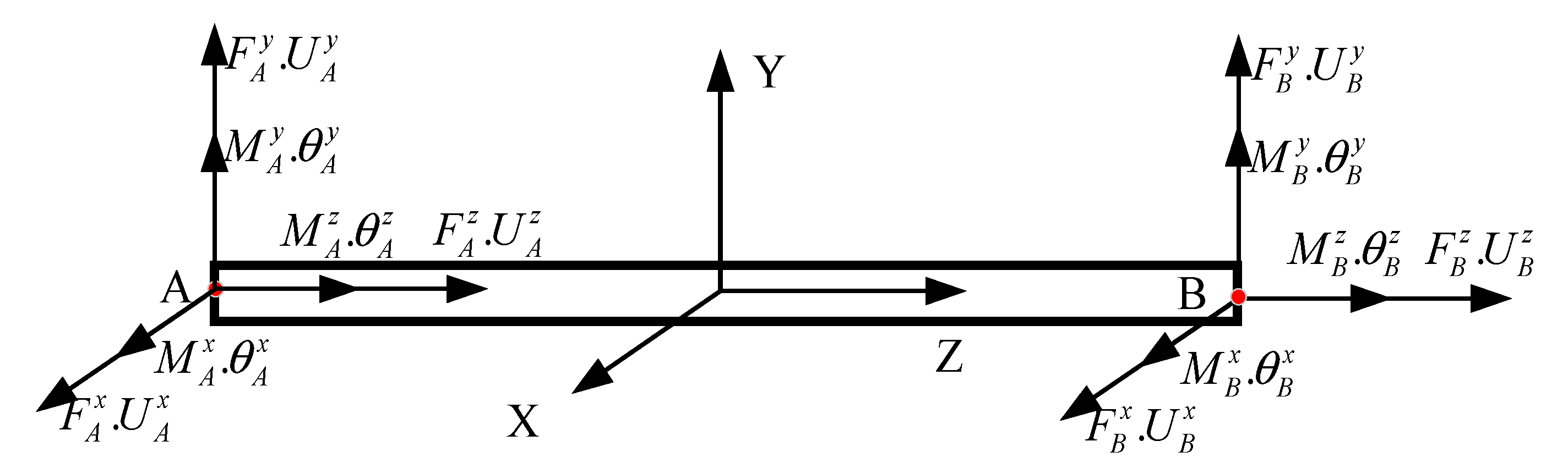
2.1. Impedance Matrix of Truss Beam

The nodal forces, moments and displacements, and rotations for vibration motions are shown in Figure 1. Points at each end have three forces, three moments, and correspondence displacements and rotations. Since this paper is intended to be used for mid- and high-frequency analysis, Timoshenko beam theory, which is considered shear deformation and rotatory, is adopted. The total variable for a single Timoshenko beam truss structure is 12.
Each truss beam has flexural, axial, and torsional vibration governing equations. To obtain the exact solutions in the frequency domain, the impedance matrix should be derived first. For example, the flexural vibration governing equation in the yoz plane can be written as [36]:
{ f y k p G A p ( u y y φ x ) = 0 m x E I p φ x y = 0 f y y ρ p A p 2 u z t 2 = 0 m x y + f y ρ p I p 2 φ x t 2 = 0
By separating variables method, the solution for Equation (1) can be written as:
u y ( z , t ) = U y ( z ) e j ω t φ x ( z , t ) = Φ x ( z ) e j ω t f y ( z , t ) = F y ( z ) e j ω t m x ( z , t ) = M x ( z ) e j ω t
Submitting Equation (2) into Equation (1), it can be simplified to only one variable Φ x in the frequency domain:
4 Φ x ( y ) y 4 + ( ρ A k p G A + ρ I E I p ) ω 2 2 Φ x ( y ) y 2 + ( ρ A k p G A ρ I E I p ω 4 ρ I E I p ω 2 ) Φ x ( y ) = 0
The solution to Equation (3) can be expressed as:
Φ x ( y ) = n = 1 4 A n e λ n y
where A n represents amplitude constants, which are decided by the boundary condition, and the flexural wave number λ n represents the four complex roots of the following equation:
λ 4 + ρ A k p G A + ρ I E I p ω 2 λ 2 + ρ A k p G A ρ I E I p ω 4 ρ I E I p ω 2 = 0
By solving Equation (5), the four wavenumbers of the flexural truss beam can be obtained as:
λ n = ± α ± α 2 4 β 2 , n = 1 , 2 , 3 , 4 α = ρ A k p G A + ρ I E I p ω 2 , β = ρ A k p G A ρ I E I p ω 4 ρ I E I p ω 2
where substituting four wavenumbers λ n into Equation (2), the functions can be written in the matrix form as follows:
[ U y Φ x M x F y ] = [ B 1 e λ 1 y B 2 e λ 2 y B 3 e λ 3 y B 4 e λ 4 y e λ 1 y e λ 2 y e λ 3 y e λ 4 y C 1 e λ 1 y C 2 e λ 2 y C 3 e λ 3 y C 4 e λ 4 y D 1 e λ 1 y D 2 e λ 2 y D 3 e λ 3 y D 4 e λ 4 y ] [ A 1 A 2 A 3 A 4 ]
where:
B n = 1 λ n 1 E I p k p G A λ n 2 + ρ I E I p ω 2 C n = E I p λ n D n = E I p λ n 2 + ρ I E I p ω 2
Up until now, the four amplitude A n constants are still unknown. If the length of a single truss beam is L, both ends of the truss beam should satisfy the impedance matrix Equation (7), which can be written as:
U 0 Φ 0 M 0 F 0 = B 1 B 2 B 3 B 4 1 1 1 1 C 1 C 2 C 3 C 4 D 1 D 2 D 3 D 4 A 1 A 2 A 3 A 4
[ U L Φ L M L F L ] = [ B 1 e λ 1 L B 2 e λ 2 L B 3 e λ 3 L B 4 e λ 4 L e λ 1 L e λ 2 L e λ 3 L e λ 4 L C 1 e λ 1 L C 2 e λ 2 L C 3 e λ 3 L C 4 e λ 4 L D 1 e λ 1 L D 2 e λ 2 L D 3 e λ 3 L D 4 e λ 4 L ] [ A 1 A 2 A 3 A 4 ]
Combining Equations (9) and (10), eliminating the A n , we can obtain the whole transfer matrix of a single truss beam as follows:
U 0 Φ 0 M 0 F 0 = B 1 B 2 B 3 B 4 1 1 1 1 C 1 C 2 C 3 C 4 D 1 D 2 D 3 D 4 B 1 e λ 1 L B 2 e λ 2 L B 3 e λ 3 L B 4 e λ 4 L e λ 1 L e λ 2 L e λ 3 L e λ 4 L C 1 e λ 1 L C 2 e λ 2 L C 3 e λ 3 L C 4 e λ 4 L D 1 e λ 1 L D 2 e λ 2 L D 3 e λ 3 L D 4 e λ 4 L 1 U L Φ L M L F L
which can be abbreviated as:
[ U 0 F 0 ] = [ T 11 T 11 T 11 T 11 ] [ U L F L ]
where U 0 = [ U 0 Φ 0 ] T , F 0 = [ M 0 F 0 ] T ; according to the relationship between the transfer matrix and impedance matrix [37,38], we can obtain the impedance matrix of truss beam in the frequency domain as follows:
Z ( ω ) = [ T 12 1 T 11 T 12 1 T 21 T 22 T 12 1 T 11 T 22 T 12 1 ]
Thus, the flexural vibration impedance matrix in the yoz plane can be written as:
F y 0 M x 0 F y L M x L = Z y o z 11 Z y o z 12 Z y o z 13 Z y o z 14 Z y o z 21 Z y o z 22 Z y o z 23 Z y o z 24 Z y o z 31 Z y o z 32 Z y o z 33 Z y o z 34 Z y o z 41 Z y o z 42 Z y o z 43 Z y o z 44 U y 0 Φ x 0 U y L Φ x L
The flexural vibration impedance in the xoz plane can also be written as:
F x 0 M y 0 F x L M y L = Z x o z 11 Z x o z 12 Z x o z 13 Z x o z 14 Z x o z 21 Z x o z 22 Z x o z 23 Z x o z 24 Z x o z 31 Z x o z 32 Z x o z 33 Z x o z 34 Z x o z 41 Z x o z 42 Z x o z 43 Z x o z 44 U x 0 Φ y 0 U x L Φ y L
The longitudinal and torsional can be written as:
f z E A u z z = 0 f z z ρ A 2 u z t 2 = 0
m z z ρ J p 2 φ z t 2 = 0 m z G J p φ z z = 0
According to the same method as flexural vibration, we can also obtain the torsional and longitudinal vibration impedance matrix of a single truss element.
F Z 0 F Z L = Z axial 11 Z axial 12 Z axial 21 Z axial 22 U Z 0 U Z L
[ M Z 0 M Z L ] = [ Z t o r s i o n a l 11 Z t o r s i o n a l 12 Z t o r s i o n a l 21 Z t o r s i o n a l 22 ] [ Φ Z 0 Φ Z L ]
So, the total impedance matrix of a single truss structure is:
[ F ˜ ] = [ Z f l e x u r a l y o z Z f l e x u r a l x o z Z a x i a l Z t o r sin a l ] [ U ˜ ] = Z [ U ˜ ]
where vectors of impedance matrix are: [ F ˜ ] = [ F y 0 M x 0 F y L M x L F x 0 M y 0 F x L M y L F z 0 F z L M z 0 M z L ] T , [ U ˜ ] = [ U y 0 Φ x 0 U y L Φ x L U x 0 Φ y 0 U x L Φ y L U z 0 U z L Φ z 0 Φ z L ] T , Z is the total impedance matrix of the truss beam.

2.2. Locally and Global Coordinate Transfer and Assemble

The above-derived impedance matrix of the truss beam structure is in a local coordinate system, but the truss structure is also complex in two and three dimensions, so we need to transfer the local coordinate system to a global coordinate system. The transfer matrix between global and local coordinates can be written as:
[ R ~ ] = cos ( x , x ~ ) cos ( y , x ~ ) cos ( z , x ~ ) cos ( x , y ~ ) cos ( y , y ~ ) cos ( z , y ~ ) cos ( x , z ~ ) cos ( y , z ~ ) cos ( z , z ~ )
where ( x ˜ , y ˜ , z ˜ ) is the globally coordinated system, ( x , y , z ) is the local coordinate system, and cos ( x , x ~ ) is the cosine function of the angle between global and local coordinate system. The total coordinate transfer matrix can be written as:
R ¯ = [ [ R ~ ] [ R ~ ] [ R ~ ] [ R ~ ] ]
The impedance matrix in the global coordinate system can be obtained from the following:
Z = i n v ( R ¯ ) Z R ¯
This coordinate transfer matrix can be used both in two- and three-dimensional truss structures. The boundary condition is easier to understand than the wave propagation approach, and ISM can be used for arbitrary boundary conditions. For example, the freedom of which point is clamped modified the stiffness of the corresponding point to a larger number. For example, the simple truss beam as shown in Figure 1, when point A is clamped in the Z-direction, assigned the total impedance matrix Z (3, 3) to a larger number. It can also be used for different kinds of boundary conditions.

3. Numerical Discussion

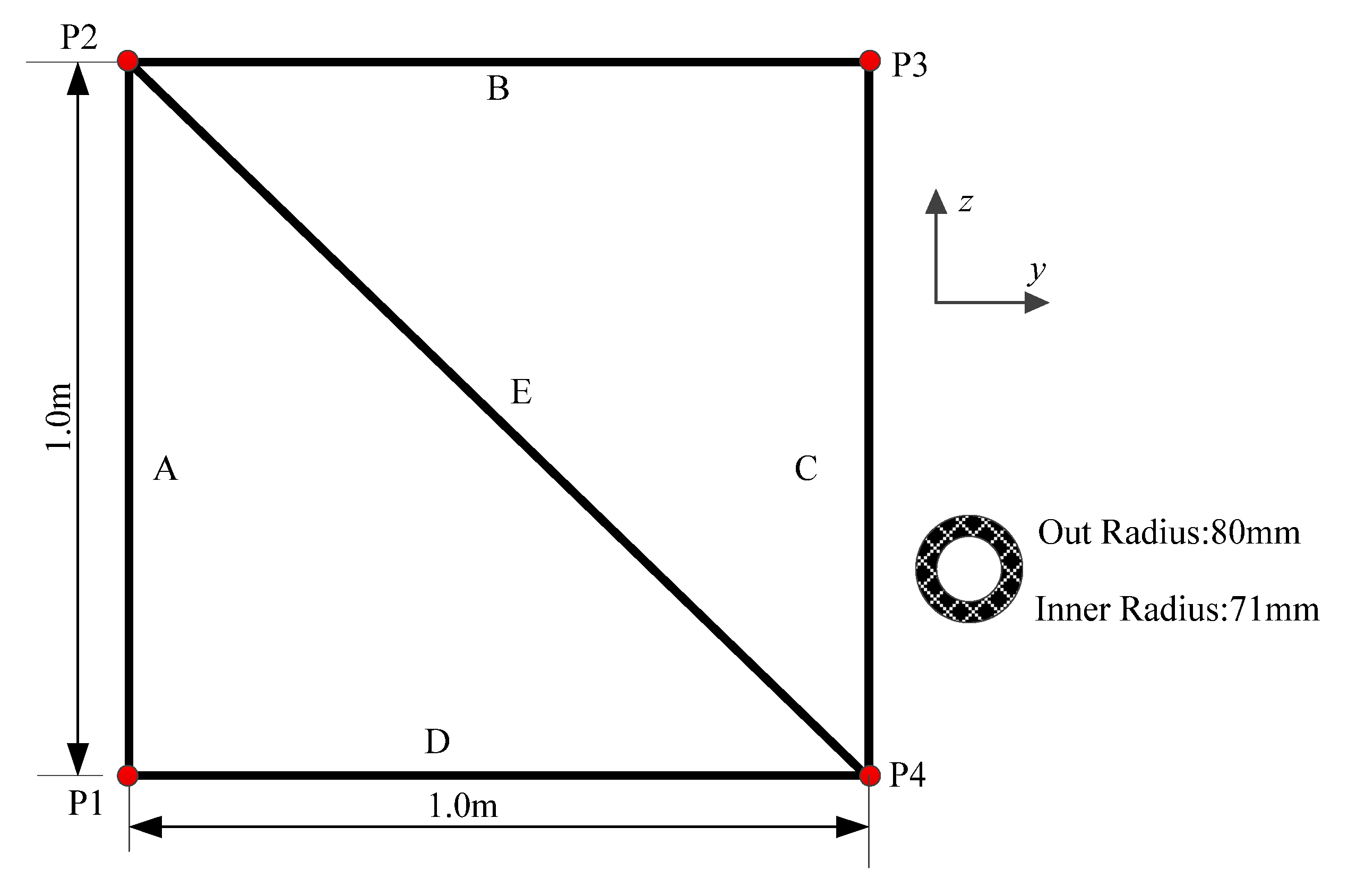
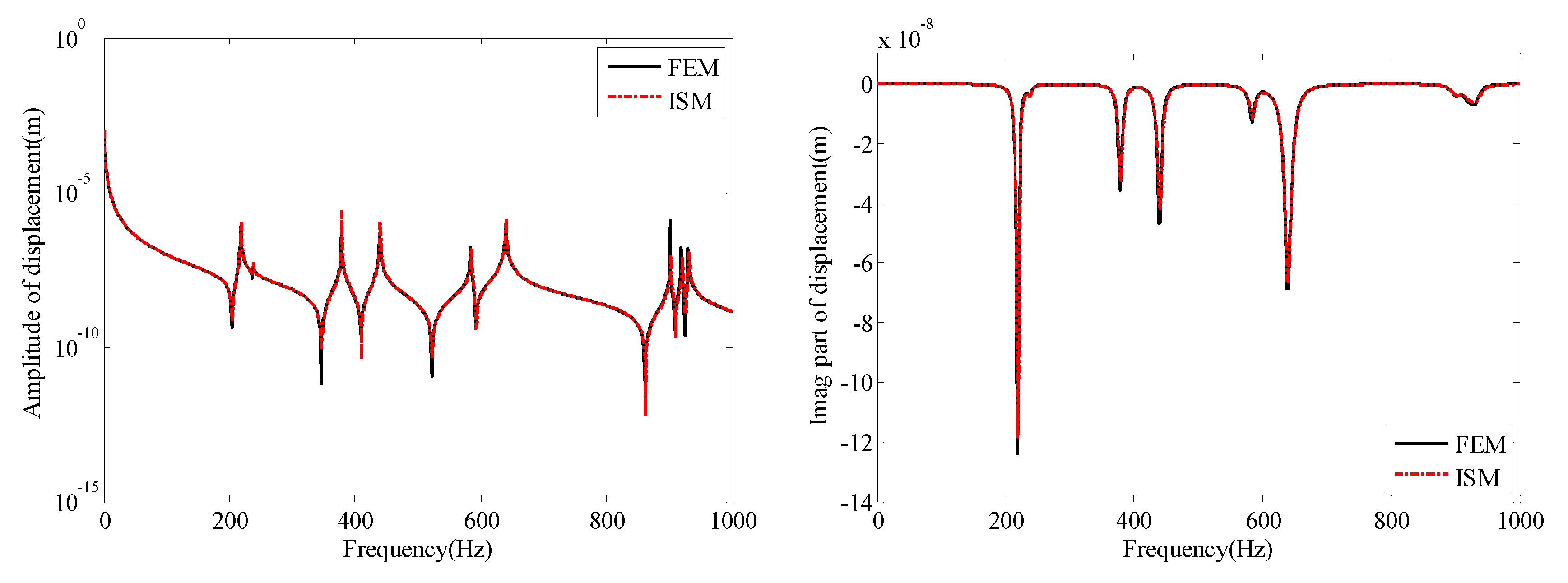
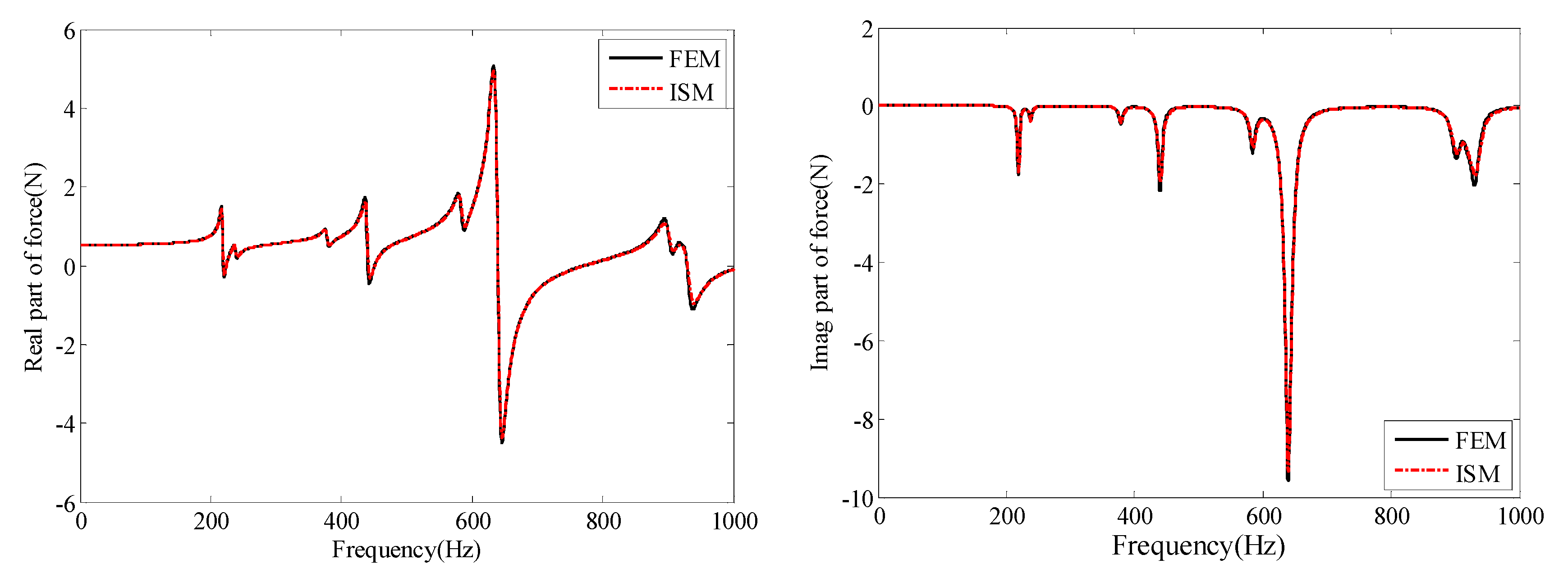
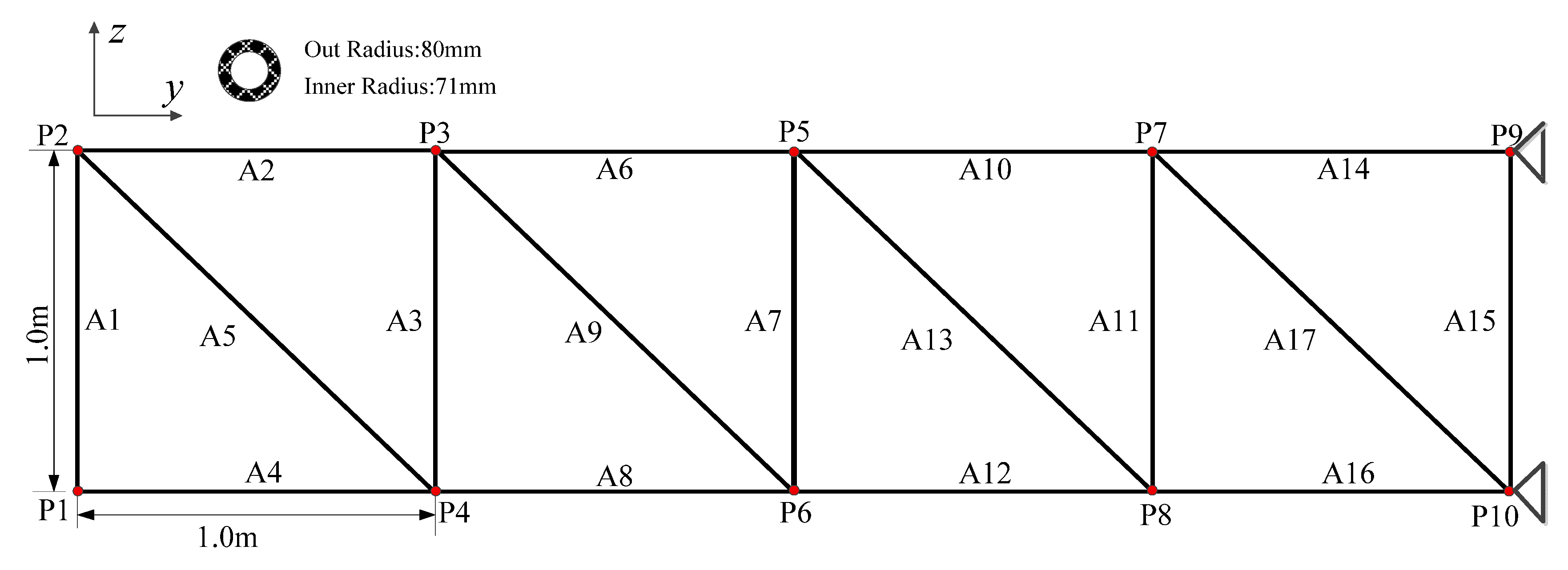
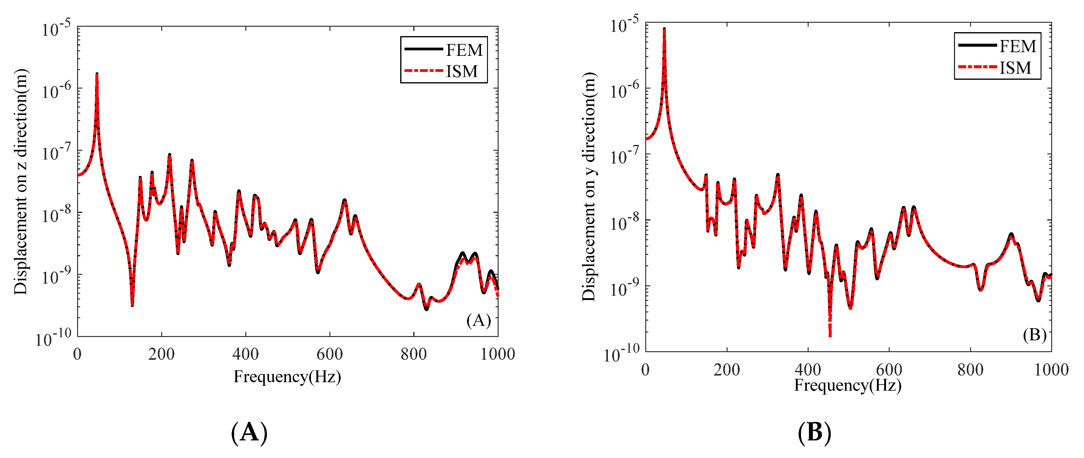
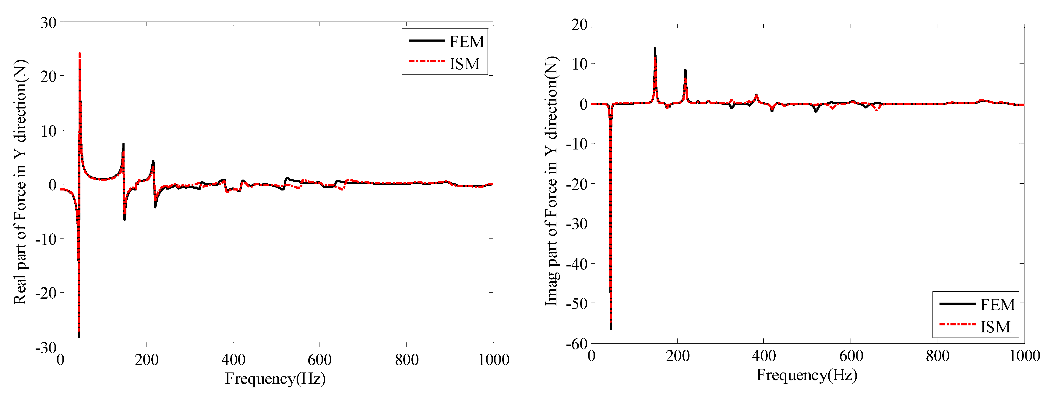
3.1. Simple Truss Structure

According to the force balance and geometric conditions at the connection point, the impedance matrix of a single truss can be used to build up the two-dimensional truss structure. For example, the simple truss structure as shown in Figure 2, consisted of five sub-structures (truss A, B, C, D, E) and four connected points (P1/P2/P3/P4). The cross-section of the beam is a pipe, and the outer radius and inner radius are 80 mm and 71 mm, respectively. Young’s modulus, density, and Poisson’s ratio of a truss are 210 GPa, 7800 kg/m3 and 0.3, respectively.
There are four connection points, each point connected with two or three beams. According to the assemble rule, the impedance matrix of the above truss structure can be written as follows:
F 1 F 2 F 3 F 4 = Z 11 A + Z 11 D Z 12 A 0 Z 12 D Z 21 A Z 22 A + Z 11 B + Z 11 E Z 12 B Z 12 E 0 Z 21 B Z 22 B + Z 11 C Z 12 C Z 21 D Z 21 E Z 21 C Z 22 C + Z 22 D + Z 22 E V 1 V 2 V 3 V 4
where:
F i = F i x F i y F i z M i x M i y M i z T V i = V i x V i y V i z θ ˙ i x θ ˙ i y θ ˙ i z T ( i = 1 , 2 , 3 , 4 )
The total impedance matrix of this simple two-dimensional truss is 24 × 24. By solving Equation (24), we can obtain the dynamic response of the truss structure. When you obtain the dynamic responses of each single truss beam, substituting them into their global impedance matrix, the dynamic forces on the left side of Equation (20) can easily be obtained. To verify the present method, the dynamic results are compared with FEM under a unit harmonic force applied on point P1 in the z-direction. The finite element model is made of the beam element, and the mesh size is 0.01 m. The element number of this simple truss is 541. The frequency analysis step is 1 Hz, and calculation frequency range is 1–1000 Hz.
The amplitude and imaginary part of dynamic displacement on point P1 in the z-direction are compared in Figure 3. It can be seen that the two results are in good agreement.
The amplitude and imaginary part of displacement of point P1 in Y direction in 1~1000 Hz domain is compared with FEM in Figure 4. We can see that both the amplitude and imaginary parts of this displacement are in good agreement too.
The vibration power flow is multiplied by the displacement and force, from the energy flow viewpoint in physics. Thus, the correctness of calculation forces also needs to be verified. Real and imaginary parts of the force on point P2 in the Z direction are compared with FEM in Figure 5. It can be seen that both real and imaginary parts of the force are in good agreement with FEM results.
From the above comparison results, one can find that the impedance synthesis method (ISM) can be used for the truss structure and has high accuracy at mid and high frequency.

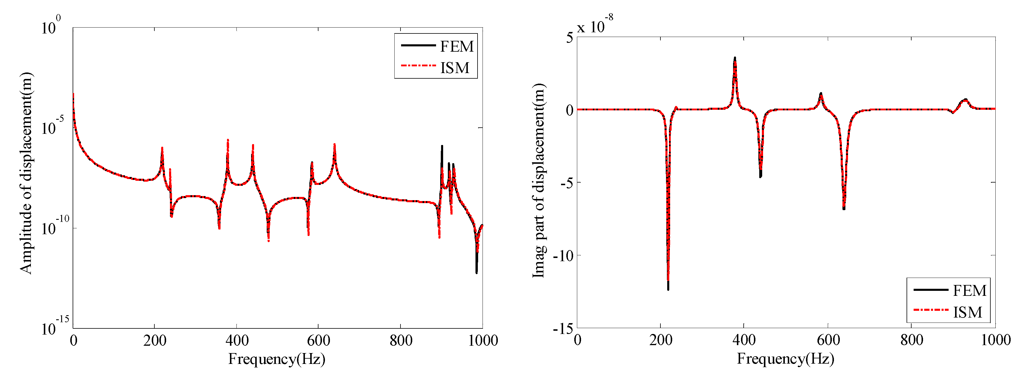
3.2. Periodic Frame Structure

The periodically two-dimensional truss structure is shown in Figure 6. The whole calculation structure should be divided into 15 sub-structures, A1–A15, and the boundary is points P9 and P10 are clamped. The cross-section of each truss is a pipe, and the inner radius is 80 mm and 79 mm, respectively. A harmonic excitation is applied on point P1 in the z-direction. The Young’s modulus, density, and Poisson’s ratio are 210 GPa, 7800 kg/m3 and 0.3, respectively. The mesh size of the finite element model is 0.01 m, there are 1864 beam elements in total, and the mass is 155.33 kg.
The y- and z-direction displacements of point P2 in the 1~1000 Hz domain are compared with FEM results in Figure 7. The two results are in excellent agreement.
In addition, the real and imaginary parts of force on point P7 in the z-direction are compared with FEM in Figure 8. It can be seen that both real and imaginary forces vary in the low-frequency range. This also means the vibration power flow is almost located in the low-frequency band.
In addition, we also compared the natural frequencies of the truss structure with results from the literature [16]. The truss structure consists of twenty substructures as shown in Figure 2. The mesh size of each beam in the finite element model is 0.01 m.
The frequency comparison results in Table 1 further verify the correctness of the calculation method in this paper.

3.3. Analysis of Vibration Power Flow

The vibration power flow of the beam can be expressed as [39]:
P = 1 2 Re F V * = 1 2 [ Re { F } Re { V } + Im { F } Im { V } ]
Because the real and imaginary parts of dynamic displacement and force are all verified above, the vibration power flow is assumed correct here. Due to the excitation force in the plane, there are only three kinds of power flow in the X, Y, and rotate Z direction. The in-plane three kinds of vibration power flow of point P2 are shown in Figure 9. They have some common peak frequencies, and in the low and high-frequency domains, power flow in the Z direction is the largest. In the middle-frequency range, all three kinds of power flow are almost the same level.
The vibration power flow of point P2 can also be divided into three sub-structure beams, A1/A2 and A5. The vibration power flow of three substructures in the Z direction is compared in Figure 10. The harmonic excitation force is applied at point P1 in the z-direction, so the input vibration power for beam A1 is mainly the axial direction. However, there exists a vibration wave transfer phenomenon on point P2; due to the geometry discontinue, we can easily see that the axial vibration power of beam A2 is smaller than the other two, especially in the low-frequency domain.
On the contract, the compared three flexural vibration power flows in the Y direction are shown in Figure 11. The vibration power flow in beam A1 is the smallest, almost in the whole frequency range. However, the vibration powers of points A2 and A5 in the Y direction are almost overlapped.
Figure 12 shows the in-plane torsional vibration power flow. We can see that the three beams are almost at the same level.
Compared to the above three figures, there are some common peak frequencies in all three kinds of vibration power flow; these are the natural frequencies of the whole dynamic truss-like model.

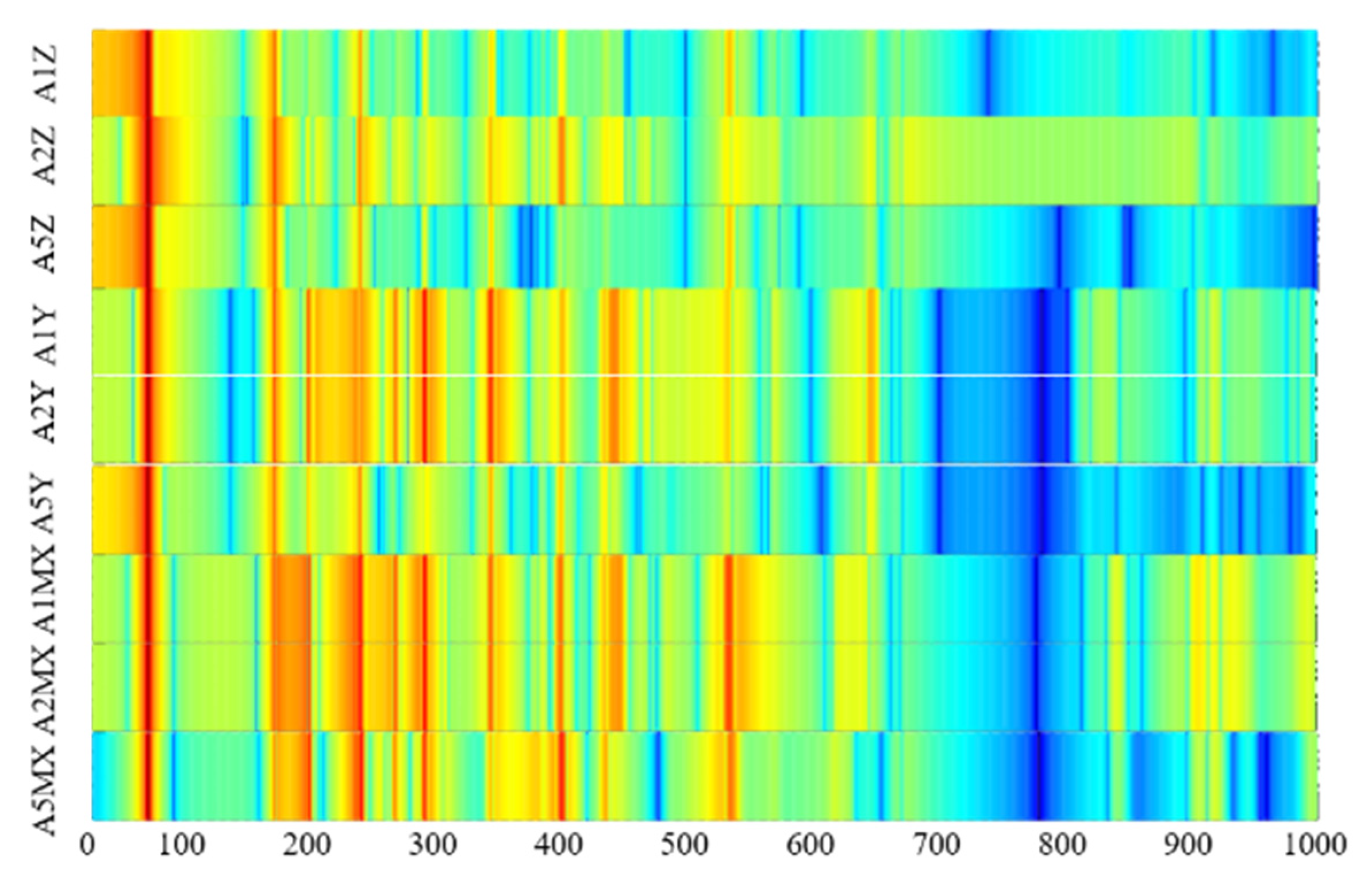
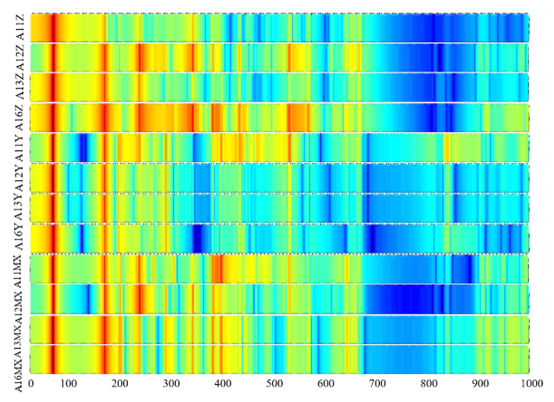
3.4. Transfer Path Analysis of Power Flow

Because the transfer path of the truss structure is complex, to reduce the unwanted vibration of the truss, we first should know the most important transfer path in the truss structure. For example, connecting point P2, there are three beams (A1, A2, and A5, as shown in Figure 6) connected at the same point P2, and each beam has its own three in-plane directions; in fact, there are a total of nine transfer paths of power flow for point P2. According to transfer path analysis (TPA) theory [40], the vibration power flow transfer path analysis of point P2 is shown in Figure 13. The more highlighted in red, the larger the vibration power flow. On the contrary, with more blue highlights, the vibration power flow is smaller.
From the contribution contour plot, we can easily find which path is the most important and transfer by which line frequency spectrum. In the low-frequency domain (1–100 Hz), this is a line spectrum of 46 Hz for all transfer paths, but A1Z, A5Z, and A5Y are the main transfer paths; these results can also be verified by Figure 10 and Figure 11. In the mid-frequency domain, the torsional vibration power flow is the main transfer path as A1MX and A2MX.
There are four beams connected to point P8; each beam also has three kinds of power flow, so there is a total of 12 vibration power flow transfer paths for point P8. The vibration power flow transfer path analysis of point P8 is shown in Figure 14.
There exist two obvious vibration line spectrums in low-frequency ranges, and A16Z is the highest contributing transfer path. The vibration power flows are basically distributed in the low- and mid-frequency domain. The results of this section can give significant advice for which frequency and which location should be considered for vibration control.

4. Conclusions

In this paper, the impedance synthesis method is proposed to build up a dynamic calculation model of a two-dimensional truss structure. The analytical method is verified by comparing with FEM results and literature. In addition, the vibration power flow of typical pints in periodic truss is analyzed. From the present investigations, the main conclusions can be drawn as follows:
(1)
The ISM can be effectively applied to investigate the dynamic responses and vibration power flow of truss-like structures, especially in mid- and high-frequency ranges;
(2)
Cross-section of the truss beam has a litter effect on the dynamic responses of the whole structure in the low-frequency domain, but can affect the dynamic responses in mid- and high-frequency ranges;
(3)
Transfer path analysis can find the main transfer path and line spectrum frequency of complex truss-like structures.
The results of this paper can give the power flow physic viewpoint of the truss structure, and this method can also be expanded to three-dimensional, honeycomb, and other truss beam structures.

Author Contributions

Methodology, H.-Z.Z. and J.-H.W.; software, J.-H.W.; validation, H.-Z.Z.; writing—original draft preparation, H.-Z.Z. and J.-H.W.; writing—review and editing, Y.-D.S.; visualization, J.-H.W.; supervision, Y.-D.S. All authors have read and agreed to the published version of the manuscript.

Funding

This work was supported by Foundation of National Key Laboratory on Ship Vibration and Noise (6142204210409). The authors also gratefully acknowledge financial support from China Scholarship Council (202008320401).

Data Availability Statement

The data that support the findings of this study are available from the corresponding author upon reasonable request.

Conflicts of Interest

The authors declare no conflict of interest.

References

  1. Liu, L.; Shan, J.; Zhang, Y. Dynamics modeling and analysis of spacecraft with large deployable hoop-truss antenna. J. Spacecr. Rocket. 2016, 53, 471–479. [Google Scholar] [CrossRef]
  2. Bondaryk, J.E. Vibration of truss structures. J. Acoust. Soc. Am. 1997, 102, 2167–2175. [Google Scholar] [CrossRef]
  3. Mehrjoo, M.; Khaji, N.; Moharrami, H.; Bahreininejad, A. Damage detection of truss bridge joints using artificial neural networks. Expert Syst. Appl. 2008, 35, 1122–1131. [Google Scholar] [CrossRef]
  4. Kaya, M.O.; Ozgumus, O.O. Flexural–torsional-coupled vibration analysis of axially loaded closed-section composite Timoshenko beam by using DTM. J. Sound Vib. 2007, 306, 495–506. [Google Scholar] [CrossRef]
  5. Aksencer, T.; Aydogdu, M. Vibration of a rotating composite beam with an attached point mass. Compos. Struct. 2018, 190, 1–9. [Google Scholar] [CrossRef]
  6. Zhou, D. Free vibration of multi-span Timoshenko beams using static Timoshenko beam functions. J. Sound Vib. 2001, 241, 725–734. [Google Scholar] [CrossRef]
  7. Lin, H.P.; Chang, S.C. Free vibration analysis of multi-span beams with intermediate flexible constraints. J. Sound Vib. 2005, 281, 155–169. [Google Scholar] [CrossRef]
  8. Wu, J.S.; Chen, C.T. A lumped-mass TMM for free vibration analysis of a multi-step Timoshenko beam carrying eccentric lumped masses with rotary inertias. J. Sound Vib. 2007, 301, 878–897. [Google Scholar] [CrossRef]
  9. Lee, J.W.; Lee, J.Y. Free vibration analysis using the transfer-matrix method on a tapered beam. Comput. Struct. 2016, 164, 75–82. [Google Scholar] [CrossRef]
  10. Jun, L.; Hongxing, H. Dynamic stiffness analysis of laminated composite beams using trigonometric shear deformation theory. Compos. Struct. 2009, 89, 433–442. [Google Scholar] [CrossRef]
  11. Zhu, H.Z.; Wang, W.B.; Yin, X.W.; Gao, C.F. Spectral element method for vibration analysis of three-dimensional pipes conveying fluid. Int. J. Mech. Mater. Des. 2019, 15, 345–360. [Google Scholar] [CrossRef]
  12. Tho, N.C.; Ta, N.T.; Thom, D.V. New numerical results from simulations of beams and space frame systems with a tuned mass damper. Materials 2019, 12, 1329. [Google Scholar] [CrossRef] [PubMed]
  13. Tho, N.C.; Thanh, N.T.; Tho, T.D.; Van Minh, P.; Hoa, L.K. Modelling of the flexoelectric effect on rotating nanobeams with geometrical imperfection. J. Braz. Soc. Mech. Sci. Eng. 2021, 43, 510. [Google Scholar] [CrossRef]
  14. Nguyen, H.N.; Hong, T.T.; Vinh, P.V.; Thom, D.V. An efficient beam element based on Quasi-3D theory for static bending analysis of functionally graded beams. Materials 2019, 12, 2198. [Google Scholar] [CrossRef] [PubMed]
  15. Nguyen Thai, D.; Minh, P.V.; Phan Hoang, C.; Ta Duc, T.; Nguyen Thi Cam, N.; Nguyen Thi, D. Bending of symmetric sandwich FGM beams with shear connectors. Math. Probl. Eng. 2021, 2021, 7596300. [Google Scholar] [CrossRef]
  16. Abbas, I.A. Three-phase lag model on thermoelastic interaction in an unbounded fiber-reinforced anisotropic medium with a cylindrical cavity. J. Comput. Theor. Nanosci. 2014, 11, 987–992. [Google Scholar] [CrossRef]
  17. Abbas, I.A.; Abo-Dahab, S.M. On the numerical solution of thermal shock problem for generalized magneto-thermoelasticity for an infinitely long annular cylinder with variable thermal conductivity. J. Comput. Theor. Nanosci. 2014, 11, 607–618. [Google Scholar] [CrossRef]
  18. Vasilyeva, M.; Ammosov, D.; Vasil’ev, V. Finite element simulation of thermo-mechanical model with phase change. Computation 2021, 9, 5. [Google Scholar] [CrossRef]
  19. An, X.; Fan, H.; Zhang, C. Elastic wave and vibration bandgaps in planar square metamaterial-based lattice structures. J. Sound Vib. 2020, 475, 115292. [Google Scholar] [CrossRef]
  20. Liu, X.; Yan, S. Bandgap and wave propagation of spring-mass-truss elastic metamaterial with a scissor-like structure. J. Phys. D Appl. Phys. 2021, 55, 055303. [Google Scholar] [CrossRef]
  21. Martinsson, P.G.; Movchan, A.B. Vibrations of lattice structures and phononic band gaps. Q. J. Mech. Appl. Math. 2003, 56, 45–64. [Google Scholar] [CrossRef]
  22. Zhang, Z.; Li, T.; Wang, Z.; Tang, Y. Band gap characteristics of flexural wave of two-dimensional periodic frame structure composed of locally resonant composite beam. Mech. Syst. Signal Process. 2019, 131, 364–380. [Google Scholar] [CrossRef]
  23. Zuo, S.L.; Li, F.M.; Zhang, C. Numerical and experimental investigations on the vibration band-gap properties of periodic rigid frame structures. Acta Mech. 2016, 227, 1653–1669. [Google Scholar] [CrossRef]
  24. Wu, Z.J.; Wang, Y.Z.; Li, F.M. Analysis on band gap properties of periodic structures of bar system using the spectral element method. Waves Random Complex Media 2013, 23, 349–372. [Google Scholar] [CrossRef]
  25. Wu, Z.J.; Li, F.M.; Zhang, C. Vibration band-gap properties of three-dimensional Kagome lattices using the spectral element method. J. Sound Vib. 2015, 341, 162–173. [Google Scholar] [CrossRef]
  26. Yong, X.; Mace, B.R.; Xisen, W. Wave propagation in periodic truss beams with members of different materials. In Proceedings of the 16th International Congress on Sound and Vibration: Recent Developments in Acoustics, Noise and Vibration, Krakow, Poland, 4–8 July 2009. [Google Scholar]
  27. Pan, J.; Hansen, C.H. Active control of total vibratory power flow in a beam. I: Physical system analysis. J. Acoust. Soc. Am. 1991, 89, 200–209. [Google Scholar] [CrossRef]
  28. Horner, J.L.; White, R.G. Prediction of vibrational power transmission through bends and joints in beam-like structures. J. Sound Vib. 1991, 147, 87–103. [Google Scholar] [CrossRef]
  29. Wang, Z.H.; Xing, J.T.; Price, W.G. Power flow analysis of indeterminate rod/beam systems using a substructure method. J. Sound Vib. 2002, 249, 3–22. [Google Scholar] [CrossRef]
  30. Signorelli, J.; Von Flotow, A.H. Wave propagation, power flow, and resonance in a truss beam. J. Sound Vib. 1988, 126, 127–144. [Google Scholar] [CrossRef]
  31. Beale, L.S.; Accorsi, M.L. Power flow in two-and three-dimensional frame structures. J. Sound Vib. 1995, 185, 685–702. [Google Scholar] [CrossRef]
  32. Rubin, S. Transmission matrices for vibration and their relation to admittance and impedance. J. Manuf. Sci. Eng. 1964, 86, 9–21. [Google Scholar] [CrossRef]
  33. Wu, J.H.; Tijsseling, A.S.; Sun, Y.D.; Yin, Z.Y. In-plane wave propagation analysis of fluid-filled L-shape pipe with multiple supports by using impedance synthesis method. Int. J. Press. Vessel. Pip. 2020, 188, 104234. [Google Scholar] [CrossRef]
  34. Wu, J.H.; Zhu, H.Z.; Sun, Y.D.; Yin, Z.Y.; Su, M.Z. Reduction of flexural vibration of a fluid-filled pipe with attached vibration absorbers. Int. J. Press. Vessel. Pip. 2021, 194, 104525. [Google Scholar] [CrossRef]
  35. Wu, J.H.; Zhu, H.Z.; Yin, Z.Y.; Sun, Y.D. Vibration wave propagation analysis of a liquid-filled pipe–plate coupled system with multiple supports. AIP Adv. 2021, 11, 025110. [Google Scholar] [CrossRef]
  36. Lesmez, M.W.; Wiggert, D.C.; Hatfield, F.J. Modal analysis of vibrations in liquid-filled piping systems. ASME J. Fluids Eng. 1990, 112, 311–318. [Google Scholar] [CrossRef]
  37. Casimir, J.B.; Nguyen, M.C.; Tawfiq, I. Thick shells of revolution: Derivation of the dynamic stiffness matrix of continuous elements and application to a tested cylinder. Comput. Struct. 2007, 85, 1845–1857. [Google Scholar] [CrossRef]
  38. Thinh, T.I.; Nguyen, M.C. Dynamic stiffness matrix of continuous element for vibration of thick cross-ply laminated composite cylindrical shells. Compos. Struct. 2013, 98, 93–102. [Google Scholar] [CrossRef]
  39. Goyder HG, D.; White, R.G. Vibrational power flow from machines into built-up structures, part I: Introduction and approximate analyses of beam and plate-like foundations. J. Sound Vib. 1980, 68, 59–75. [Google Scholar] [CrossRef]
  40. van der Seijs, M.V.; de Klerk, D.; Rixen, D.J. General framework for transfer path analysis: History, theory and classification of techniques. Mech. Syst. Signal Process. 2016, 68, 217–244. [Google Scholar] [CrossRef]
Figure 1. Notation for forces/moments and displacements/rotations of a beam.
Applsci 12 08863 g001
Figure 2. Two-dimensional frame structure.
Applsci 12 08863 g002
Figure 3. Displacement comparison of ISM and FEM of point P1 on the Z direction.
Applsci 12 08863 g003
Figure 4. Displacement comparison of ISM and FEM of point P1 in Y direction.
Applsci 12 08863 g004
Figure 5. Force comparison of ISM and FEM of point P2 on the Z direction.
Applsci 12 08863 g005
Figure 6. Scheme periodic frame structure.
Applsci 12 08863 g006
Figure 7. Dynamic responses of point P2 compared with FEM: (A) in z direction, (B) in y direction.
Applsci 12 08863 g007
Figure 8. Force comparison of ISM and FEM of point P7 in the Z direction.
Applsci 12 08863 g008
Figure 9. Vibration power flow of P2 in the z-direction.
Applsci 12 08863 g009
Figure 10. Vibration power flow of P2 in the Z direction.
Applsci 12 08863 g010
Figure 11. Vibration power flow of P2 in Y direction.
Applsci 12 08863 g011
Figure 12. Vibration power flow of P2 in MX direction.
Applsci 12 08863 g012
Figure 13. Vibration power flow transfer path analysis of P2.
Applsci 12 08863 g013
Figure 14. Vibration power flow transfer path analysis of P8.
Applsci 12 08863 g014
Table 1. Comparison of the natural frequency with literature.
Modes No.12345678
Zuo [23]4.7127.5870.0985.58122.55176.45224.25232.45
FEM (400 elements)4.7127.5870.1685.68122.94177.81228.60236.88
FEM (800 elements)4.7127.5870.1185.60122.65176.73225.24233.45
The present4.7127.5870.0885.57122.55176.38224.10232.30
Publisher’s Note: MDPI stays neutral with regard to jurisdictional claims in published maps and institutional affiliations.

