Article

Motion Generation for Crane Simulators Using Streamlined Motion Blending Technology

1
School of Transportation and Logistics Engineering, Wuhan University of Technology, Wuhan 430063, China
2
Technical Engineering Department of Port Dalian Bulk Cargo Terminal Company, Dalian 116001, China
3
School of Art and Design, Wuhan University of Technology, Wuhan 430070, China
*
Author to whom correspondence should be addressed.
Appl. Sci. 2022, 12(17), 8799; https://doi.org/10.3390/app12178799
Submission received: 10 August 2022 / Revised: 29 August 2022 / Accepted: 31 August 2022 / Published: 1 September 2022
(This article belongs to the Special Issue New Frontiers in Advanced Manufacturing)

Abstract

:
For development of a simulator with a motion platform to generate an appropriate motion to reproduce the motion sense for the users, one of the most significant but disregarded complicated tasks is to build up a dynamic virtual motion model to reflect the motion of the simulated object in the corresponding physical world. Recently, a motion generation method based on motion blending technology was developed to alleviate the complication involved. It decomposes the simulated motion into a great number of parameterized motion blocks which are depicted by real motion data acquired from field tests and stored in a database. This paper proposes a streamlined motion blending technology suitable for a container crane simulator to further improve the current motion generation method based on the motion blending technology. Motion components, rather than motion blocks specially marked and stored in a database, are taken as the basic motion unit easily acquired through united analysis of crane dynamics and motion perception characteristics. They are then blended on demand to produce a one-stop model to directly act as the driving command of the motion platform without the need for a subsequent dedicated wash-out procedure. The calculation workload is greatly reduced and finally allows for achievement of higher fidelity of motion perceptions. Experiments are conducted to verify the effectiveness of the proposed streamlined motion blending technology for motion perception generation. Better training effect is found to be achieved due to more realistic simulation effects. The comprehensive training effectiveness index is enhanced from 54% to 82% once a motion simulation system developed using the proposed approach is introduced into the crane simulator.

1. Introduction

Driven by the trend of the continuous penetration of unmanned intelligent control technology into almost all industrial sectors, the idea of unmanned fully automatic container quayside container crane has also been suggested for many years. However, due to technical difficulties, there is still no sign that the unmanned container crane can be put into practical use in a short period of time [1]. At present, in the actual container terminals, the traditional manually operated quayside cranes still account for the vast majority of the total. According to the survey data obtained from Ningbo port in China, about 75% of the quayside cranes in service are still manually operated. For these manually operated quayside cranes, one of the most challenging problems is how to train novice operators to successively take over from the retiring workers. Using crane simulators to train new crane operators has proved to be a very effective method in that it has the advantages of saving cost, improving safety, not occupying the real equipment in service, not being restricted by adverse environmental conditions, and so on [2].
The quayside container crane simulator has appeared for many years, and its performance has been greatly improved through the continuous efforts of a large number of scholars. The early research mainly focused on how to model the real-time dynamics of the related components and the assemblies of the crane manipulated by the trainees in the virtual space, especially to detect the possible collision in real time so that the best visual effect is achieved through the rendering process of the visual system in order to provide the operator with a highly realistic real-time dynamic immersion [1,3,4]. Another significant research problem that researchers focus on is how to design the simulator system architecture and quickly integrate together all the components involved in the entire virtual simulation system [5,6,7] including the motion platform [8,9,10]. Although the motion platform is considered to be an important part of the crane simulator, profound research is very lacking, and it is often regarded as a supplementary part of the system architecture design of the whole simulation system. Lu et al. studied the functional and structural design of the motion platform in the quayside container crane simulator and discussed the motion generation algorithm for providing the motion perception through the motion platform as well as the software implementation [9]. The motion generation algorithm in this case is nevertheless a straightforward application of the traditional motion cueing algorithm including a washout process, which was originally and has now been widely used in vehicle simulators. Transplanting the motion cueing algorithm [11,12,13,14,15,16,17] on the vehicle simulator to the motion platform of a crane simulator [18,19,20,21,22,23] can indeed solve some of the problems that will be encountered in the implementation of the system, but it is not the whole problem or even the main problem of crane motion perception simulation. In fact, for the crane simulator, this problem is not prominent as there are only a very few parts of the movements resulted from low-frequency continuous acceleration and continuous deceleration, for which the traditional washout algorithm is most effective to prevent the motion platform from exceeding its working space range when reproducing the motion in reality. The real difficulty of crane motion perception simulation is how to obtain a suit of suitable and easy-to-handle motion equations to reflect the current simulation conditions and parameterized user demands and then generate an equivalent motion on the platform with almost the same motion perception. Furthermore, the motion generation approach needs to be optimized by comprehensively considering the motion perception characteristics of the crane.
Recently, Cha et al. proposed a motion generation approach based on the motion blending technology [24,25], which seems to be methodologically applicable to solve the crane motion perception simulation problem. According to this approach, regeneration of the motions perceptible to operators on the simulator can be divided into two steps. The first step is to generate a motion flow, and the second step is to apply a wash out algorithm to the motion flow to ensure that the motion could be realized on the motion platform on the premise of motion perception similarity. The main contributions of this approach mainly lie in the first step, and the second step is a direct application of the typical wash out algorithm. The whole motion bulk data are divided into some motion blocks which are stored in the database. In real-time simulation, a natural motion stream is generated by optimally synthesizing a set of motion blocks retrieved from the database to reflect the current simulation conditions and user demands [24]. In the process of searching and synthesizing optimal motion blocks, vehicle dynamics-based parameterization can also be included in the work flow to make the motion blending approach more effective by combining dynamics-driven motion and data-driven motion in a hybrid way [25]. Since the motion block concept is not applicable to the crane motion simulation, the motion generation approach based on motion blending technology only provides a possible clue for current study. In summary, on the one hand, all the current crane simulators are highly in need of being enabled with more realistic motion simulation, while on the other hand, the traditional motion cueing algorithm widely used in vehicle simulators or other similar areas should have little usefulness if plainly exploited without radical improvements. This motivates the current study to develop a novel motion generation approach dedicated to motion perception simulation for quayside container cranes. The approach developed is based on the streamlined motion blending technology, which is an improvement to the motion generation algorithm based on the motion blending technology proposed by Cha et al. The improvements are reflected in two aspects. Firstly, motion components, rather than motion blocks specially marked and stored in a database, are taken as the basic motion unit easily acquired through united analysis of crane dynamics and motion perception characteristics. Secondly, each motion component either directly acts as the driving command of the motion platform without subsequent washout processing, or directly incorporates the washout algorithm effects into the models.
It is noted that the proposed streamlined motion blending technology used for motion generation for crane simulators has many advantages for implementation. Two steps of modeling and calculation tasks are now combined into one task. Redundant data conversion links are eliminated. The technical realization route is more concise and clearer. The calculation workload is greatly reduced and finally allows for the achievement of more realistic simulation effects and higher fidelity of motion perceptions. Experiments are conducted to verify the effectiveness of the proposed motion perception simulation approach based on streamlined motion blending technology.
The rest of this paper is organized as follows. Section 2 analyzes the characteristics of the crane motion from the view point of the motion perception and overviews application of conventional motion generation technologies for crane simulators. Section 3 elaborates the proposed streamlined motion blending technology for crane motion simulation. Section 4 describes modeling of typical motion components. System implementation and application effect evaluation through experiments are reported in Section 5. Finally, in Section 6, concluding remarks are drawn and future research directions discussed.

2. Motion Generation Technology for Crane Simulator

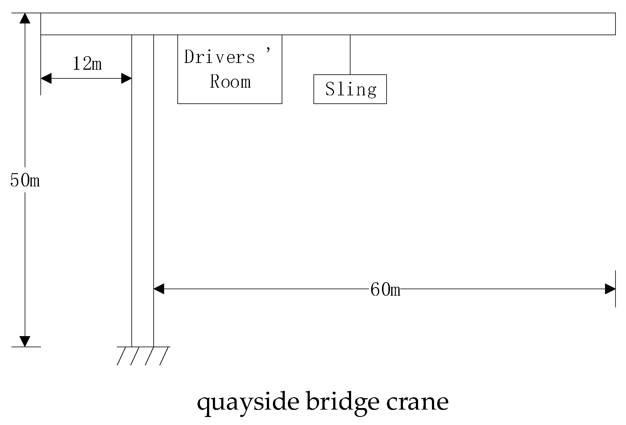
2.1. The Characteristics of Crane Motion
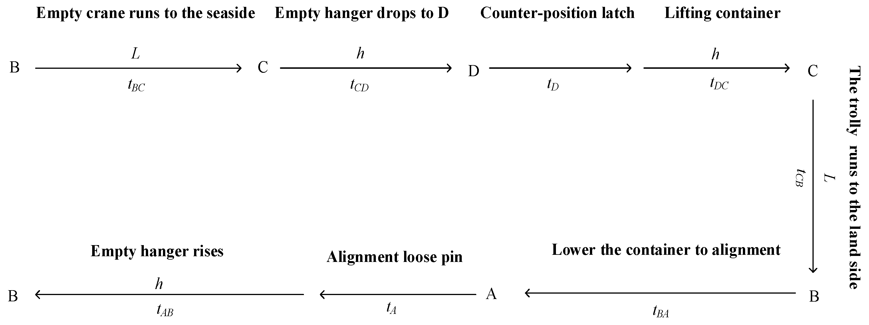
Taking the quayside container crane shown in Figure 1 as an example, the motion characteristics of its cab are illustrated. During the movement of the driver’s cab, a motion coordinate system OXYZ is established based on the centroid of the driver’s cab. The motion of the center of mass in the cab is equivalent to the motion of the planar centroid on the 6-DOF motion platform, and the reference coordinate system required to reproduce the simulated motion is established accordingly. It ensures that the motion simulation can be coordinated with the visual output.
According to the principle of human motion perception, the human perception thresholds for angular velocity and linear acceleration are approximately 3°/s and 0.2 m/s2, and motion above these thresholds can only be perceived by the human body. According to the above criteria to identify the crane cab can be perceived by the driver’s motion (referred to as motion) and inductive analysis, the following characteristics can be found.

2.1.1. Periodicity

The quay crane always moves continuously in a cycled and repeated way under the same or similar operating conditions according to the fixed route. The single cycle route of the quay cranes during unloading operation is shown in Figure 2, where A, B, C, and D are the four points that can be reached in the operation process, L is the operating length, h is the lifting height, and t is the operating time.

2.1.2. Motion Decomposability

There are two kinds of motion in the cab: one is the large-scale low frequency motion caused by the acceleration or deceleration of the trolley. The other is the small-scale high frequency motion caused by various vibration sources. The motion of the crane can be decomposed into a number of large-scale motion components and several vibration components. After these components are calculated separately, the overall motion signal is superimposed after coordination and alignment in the time domain.
Through the decomposability of crane motion, this paper presents a new rule for the process of high-fidelity motion simulation.
The acceleration signal that moves along the coordinate axis is defined as ( x · · , y · · , z · · ) , and the rotational speed signal that rotates around the coordinate axis is defined as ( α · , β · , γ · ) . Then, the motion signal of the crane is M = ( x ( t ) , y ( t ) , z ( t ) , α ( t ) , β ( t ) , γ ( t ) ) .
Let the motion M contain n motion components, and each motion component M i ( t ) can be independently modeled for solution and can be expressed as:
M i = M i ( t ) = ( x i ( t ) , y i ( t ) , z i ( t ) , α i ( t ) , β i ( t ) , γ i ( t ) ) , i = 1 , 2 , n
where x i ( t ) , y i ( t ) , z i ( t ) is the distance of translation around the X, y and Z coordinate axes, and α i ( t ) , β i ( t ) , γ i ( t ) is the distance of rotation around the X, y and Z coordinate axes.
Each motion component M i ( t ) is triggered at t = t 0 i . The total amount of motion can be expressed as:
M = i = 1 n M i ( t t 0 i )
where t 0 i is the initial time of each motion component.
Therefore, as long as the type and quantity of M i ( t ) , the solution method of M i ( t ) and which M i ( t ) is triggered at each moment are confirmed, and the motion simulation problem of crane can be close to completely solved.

2.1.3. Predictability

The specific structure and working environment of the crane determine that the motion of the driver’s cab can be easily predicted in terms of basic form, variation law, and variation range. The t B C section is shown in Figure 2; the trolley at this stage passes through acceleration, uniform speed, deceleration, and stop, which is a very typical low-frequency speed change process running according to the trapezoidal curve in the motion process of the crane, as shown in Figure 3.
In this stage, when the front wheel of the trolley reaches the rail gap between the front beam and the rear beam, there will be an obvious vibration in the driver’ s room, which will be triggered and terminated by natural attenuation.
The motion analysis under different working conditions is similar, and the dynamic motion of the quayside bridge can be summarized into nine cases, as shown in Table 1. Each movement involves one or more directions and can be characterized by a model, which confirms the predictability of crane motion.

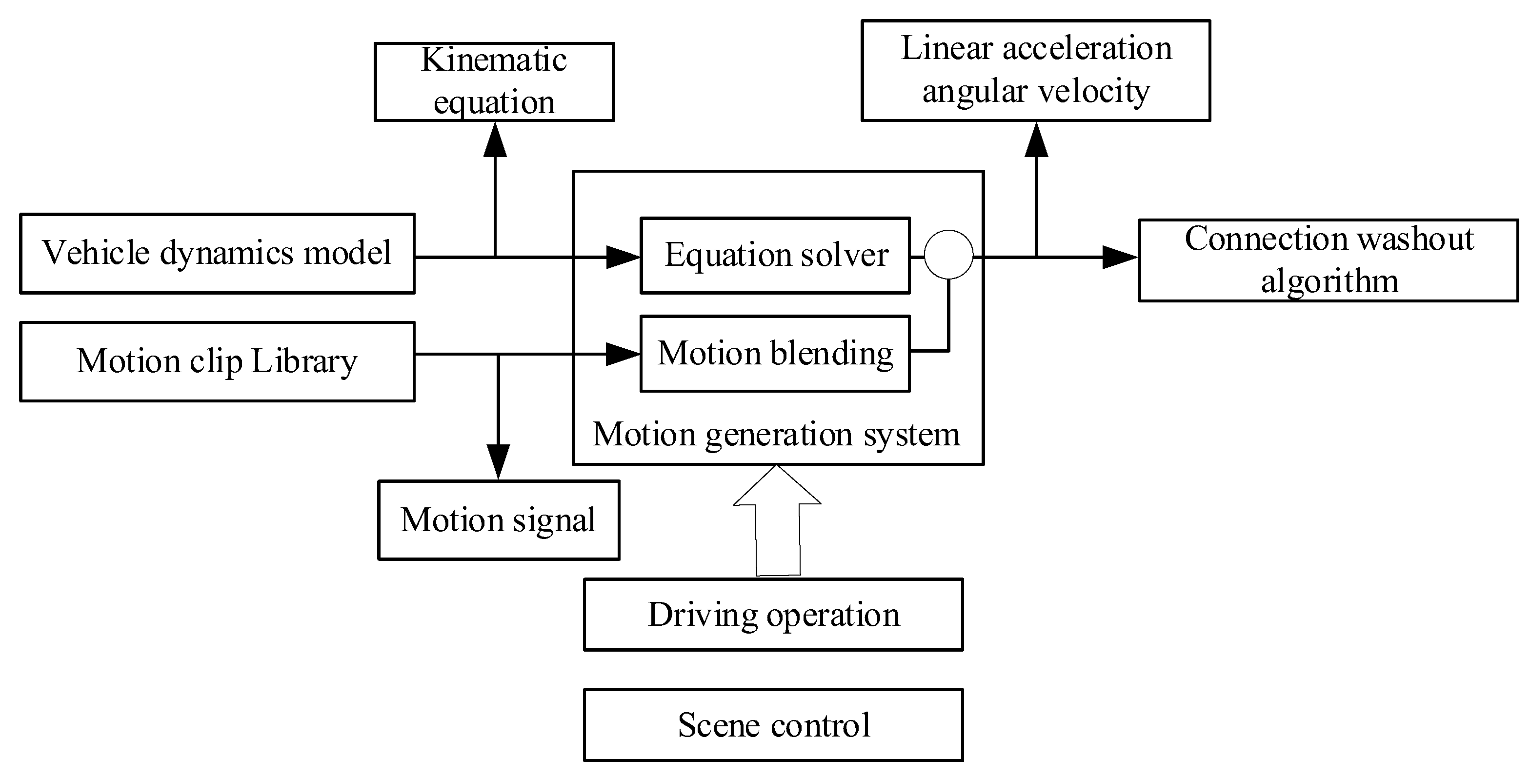
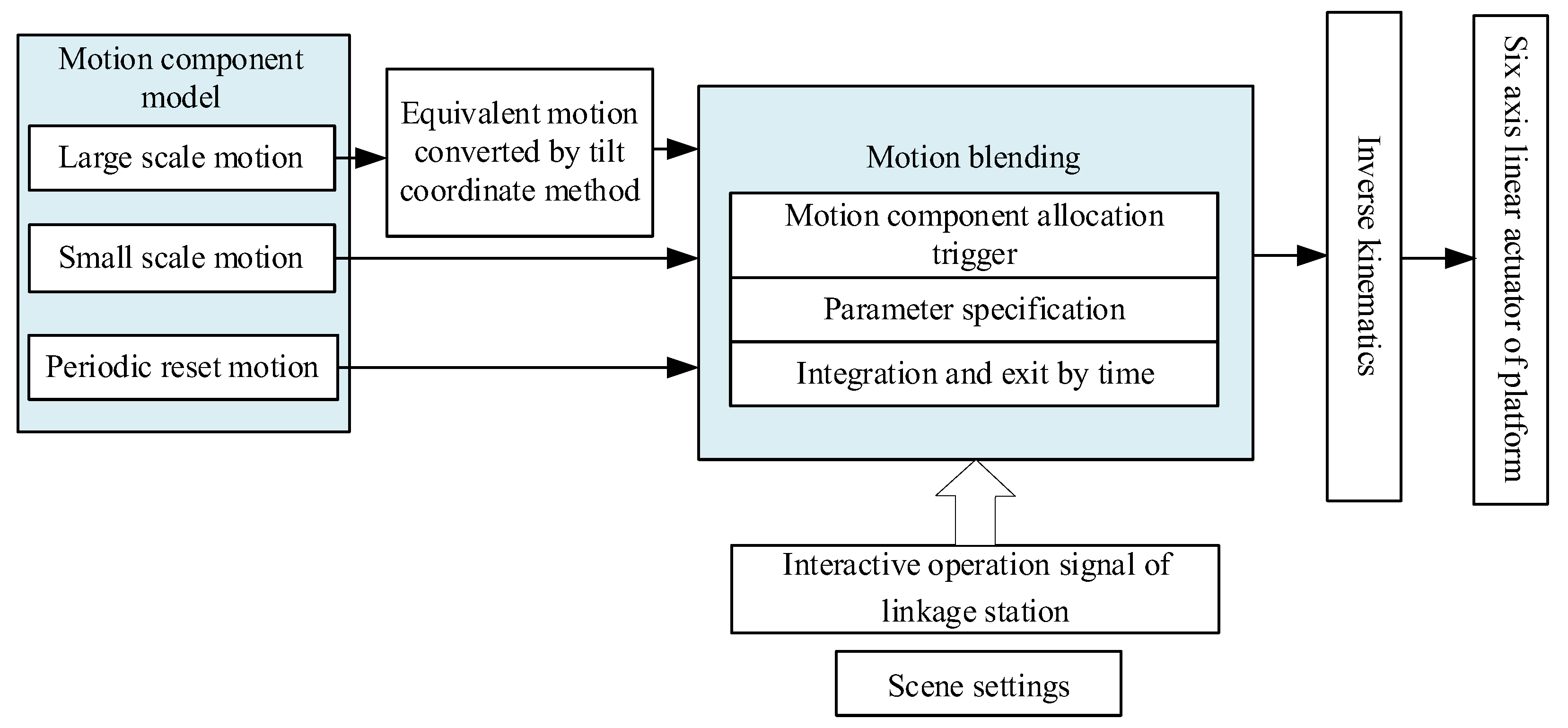
2.2. Motion Generation Based on Motion Blending Technology

Motion generation based on motion blending technology is proposed by Cha M. on the basis of classical washout algorithms (Figure 4), which is used to improve the dynamic fidelity of the trolley driving simulator. In order to establish a more perfect motion synthesis rule, a simplified dynamic model is also combined in the reconstruction of the motion model through the motion fragment database. Under the guidance of the model, the system will automatically search the motion fragment library according to the real-time motion state after parameterization and preprocessing to complete the superposition of the optimal motion fragments. The flowchart is shown in Figure 5.
The motion of the crane can be decomposed into about eight kinds of meta-motions naturally, so the method of motion blending is especially suitable for generating the initial motion command stream in crane motion simulation. The decomposed meta-motions can be directly described by the model. These models can be activated by the driver’ s scene setting signal and the real-time interactive operation signal of the linkage table. After appropriate parametric adjustment, the motion flow that meets the requirements of motion simulation can be synthesized on the time axis. After obtaining the motion flow, it can be directly output to the input of the classical washout algorithm to realize the motion simulation of the crane, as shown in Figure 6.

3. Streamlined Motion Blending Technology for Crane Motion Simulation

3.1. Analysis of Streamlined Motion Blending Technology

The crane motion simulation scheme based on motion blending shown in Figure 6 can also be further optimized according to the characteristics of crane motion. In the motion components of the crane, the large-scale low-frequency motion caused by the acceleration and deceleration of the trolley needs to be separated by low-pass filtering, and replaced by the tilt coordinate method with the equivalent rotation motion. The motion platform can reproduce other small-scale high-frequency motions. Since the low-frequency motion and high-frequency motion are naturally separated from each other from the moment they are generated, it is only necessary to combine the low-frequency channel motion components converted by the tilt coordinate method with the high-frequency channel motion components as the final driving instructions issued to the motion platform to realize the motion simulation of the crane motion with high fidelity.
The structural diagram of the motion simulation system of the streamlined crane proposed in this paper is based on the improvement of the traditional motion blending technology (as shown in Figure 7). Though, for this way to develop a dynamic simulation system, the technical route is clearer, the workload is greatly reduced, and the real-time performance is stronger.
Table 2 makes a detailed comparison between the existing motion blending technology in motion simulation and the streamlined motion blending technology proposed in this paper. It can be seen that the streamlined motion blending technology is consistent with the existing motion blending technology in principle, so it has a reliable theoretical basis. At the same time, the latter fully combines the characteristics of crane motion so that the calculation efficiency of the algorithm is higher.

3.2. Structure of Streamlined Motion Blending Algorithm

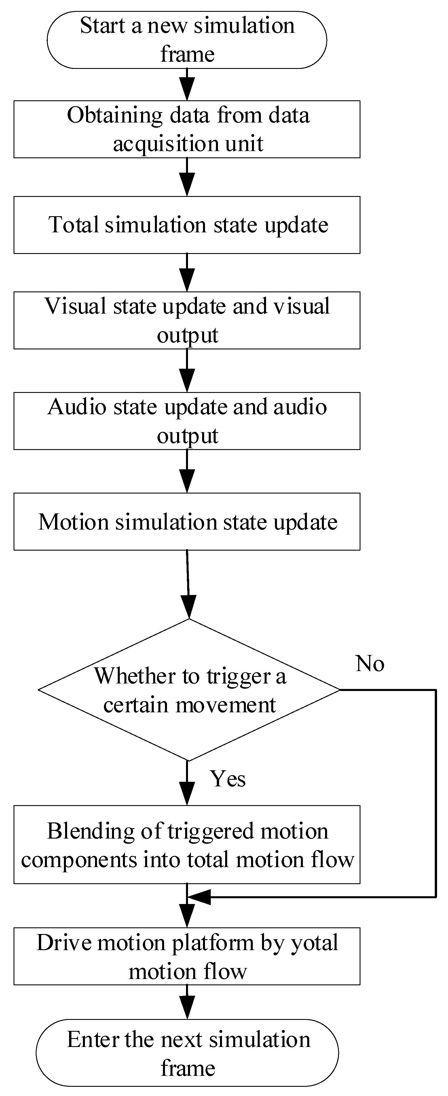
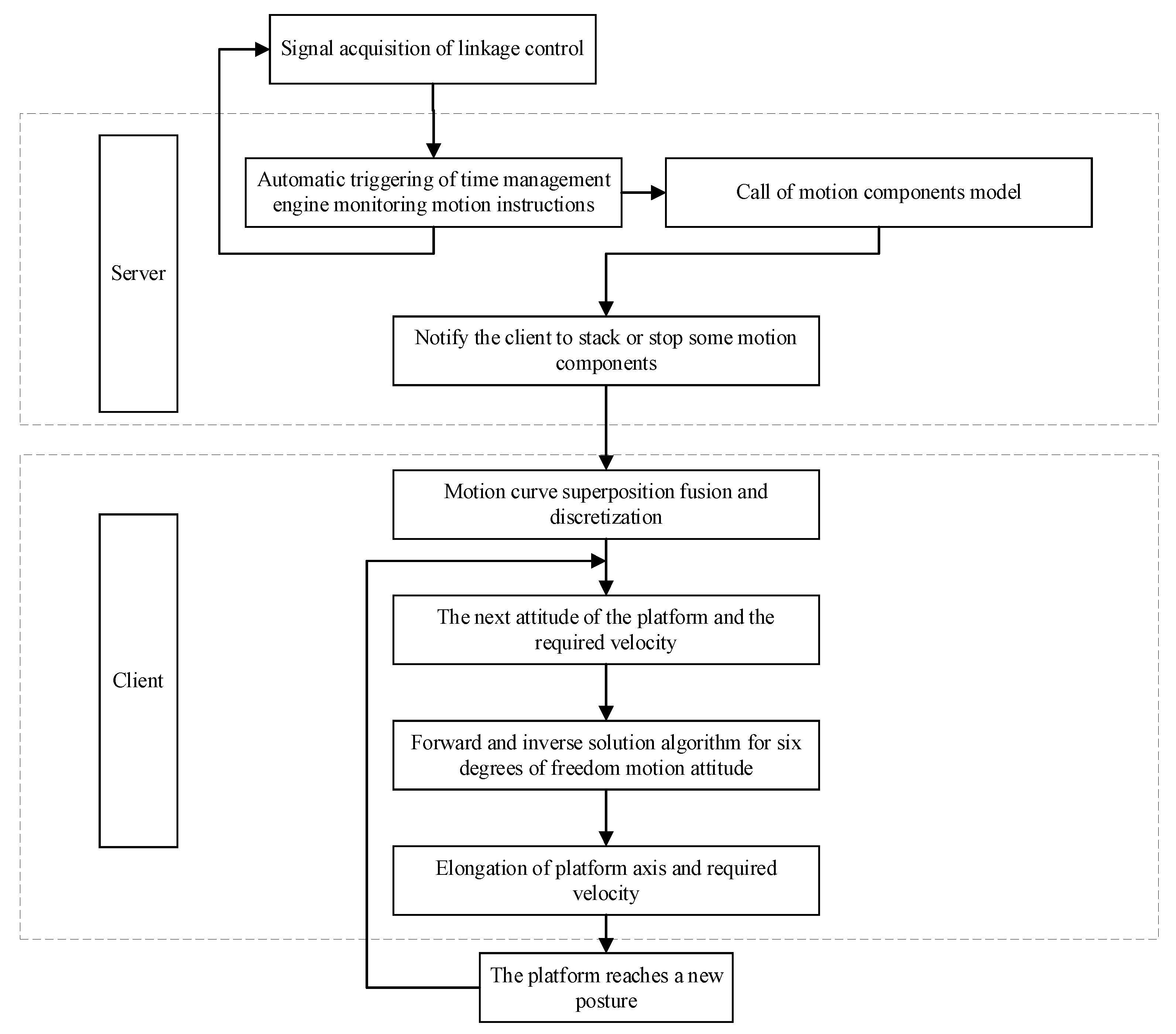
3.2.1. Flow Chart of Streamlined Motion Blending

After the motion simulation process is initialized, all motion components are triggered at any time on demand. The time engine in the real-time master computer judges whether to trigger a certain motion component according to the change of the operating conditions of the crane captured in the input signal. Once triggered, it will automatically overlap according to the principle of coordinate component alignment, so that it becomes a member of the current active motion components set. The motion components are characterized as a function of time. With the passage of time or when the reset instruction is detected by the time engine, the triggered motion components may automatically disappear from the current active motion components set. Otherwise, they will stay in the current active motion components set. This core logic of motion blending is put into the operation cycle of the entire starter simulator, and the overall control process is shown in Figure 8.

3.2.2. Calling Method of Motion Components

If the driver’s final track of the motion is regarded as a set of time-varying curves along the X, Y, Z, α, β, and γ coordinates, then each triggers a new motion component that is equivalent to the superposition of a set of new time-varying curves aligned with the original curve by coordinates. There are two other exceptions. One is to delete a set of curves in the existing motion curve combination, and the other is to perform a reset operation.
In this project, a set of curves that overlay and delete a motion component adopts a unified instruction form: AddLayer (A [], b). Among them, array A [] calls all the parameters needed for the motion component curve. b is a 7 bit 0 / 1 symbol, the first bit 0 means stopping the bar or the group of existing curves, 1 means increasing; bits 2 to 7 indicate whether the curve is applicable to one or several of six degrees of freedom. The nine motion components in Table 1 are called in this way.

3.2.3. Streamlined Motion Blending Algorithm Pseudocode

Motion simulation is regarded as a part of the real-time master control process driven by the main time engine according to the beat (frame). It is very easy to write the algorithm shown in Figure 8 into the following pseudocode (Algorithm 1):
Algorithm 1. Streamlined Motion Blending Algorithm
Start a new time frame; # Start a new simulation frame
Read data from the DAQ Unit; # Read data from data acquisition unit
Renew the status of the simulated crane; # Total simulation state update
{Renew rendering status; # Visual state update
    Render;} # Visual output
{Renew audio output status; # Audio state update
Output audio;} # Audio output
{Renew motion cueing status; # Motion simulation state update
  Do case; # The following is the main algorithm of motion simulation
case IsCase1=TRUE;
AddLayer(A1[], b1);
case IsCase2=TRUE;
AddLayer(A2[], b2);
case IsCase3=TRUE;
AddLayer(A3[], b3);
case IsCase4=TRUE;
AddLayer(A4[], b4);
case IsCase5=TRUE;
AddLayer(A5[], b5);
case IsCase6=TRUE;
AddLayer(A6[], b6);
case IsCase7=TRUE;
AddLayer(A7[], b7);
case IsCase8=TRUE;
AddLayer(A8[], b8);
case IsCase9=TRUE;
AddLayer(A9[], b9);
case IsCase10=TRUE;
ResetPlatform;
Endcase;}
If TimeIsUp=FALSE;
Then Nooperation;
Else Return; # Time to this frame, return to the next frame

4. Modeling of Typical Motion Components

Several typical motion components in Table 1 are modeled below, and the modeling of other motion components are similar.

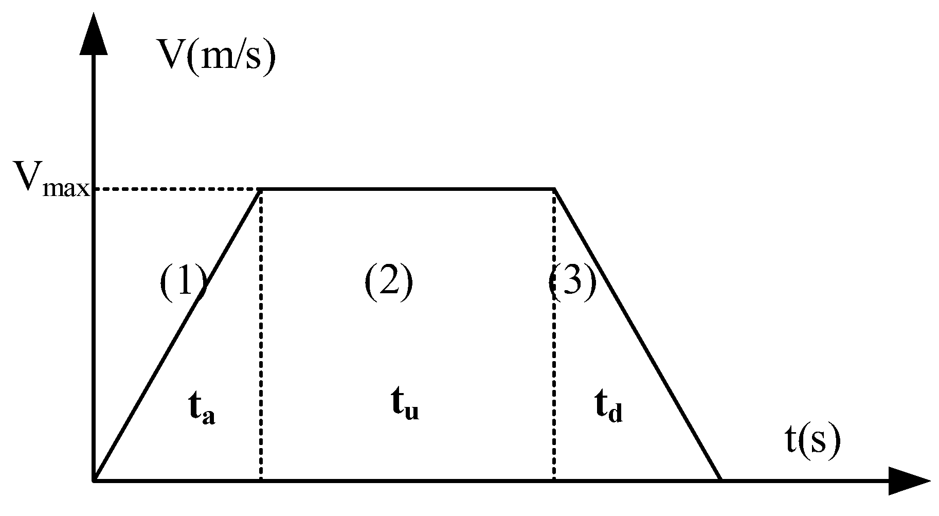
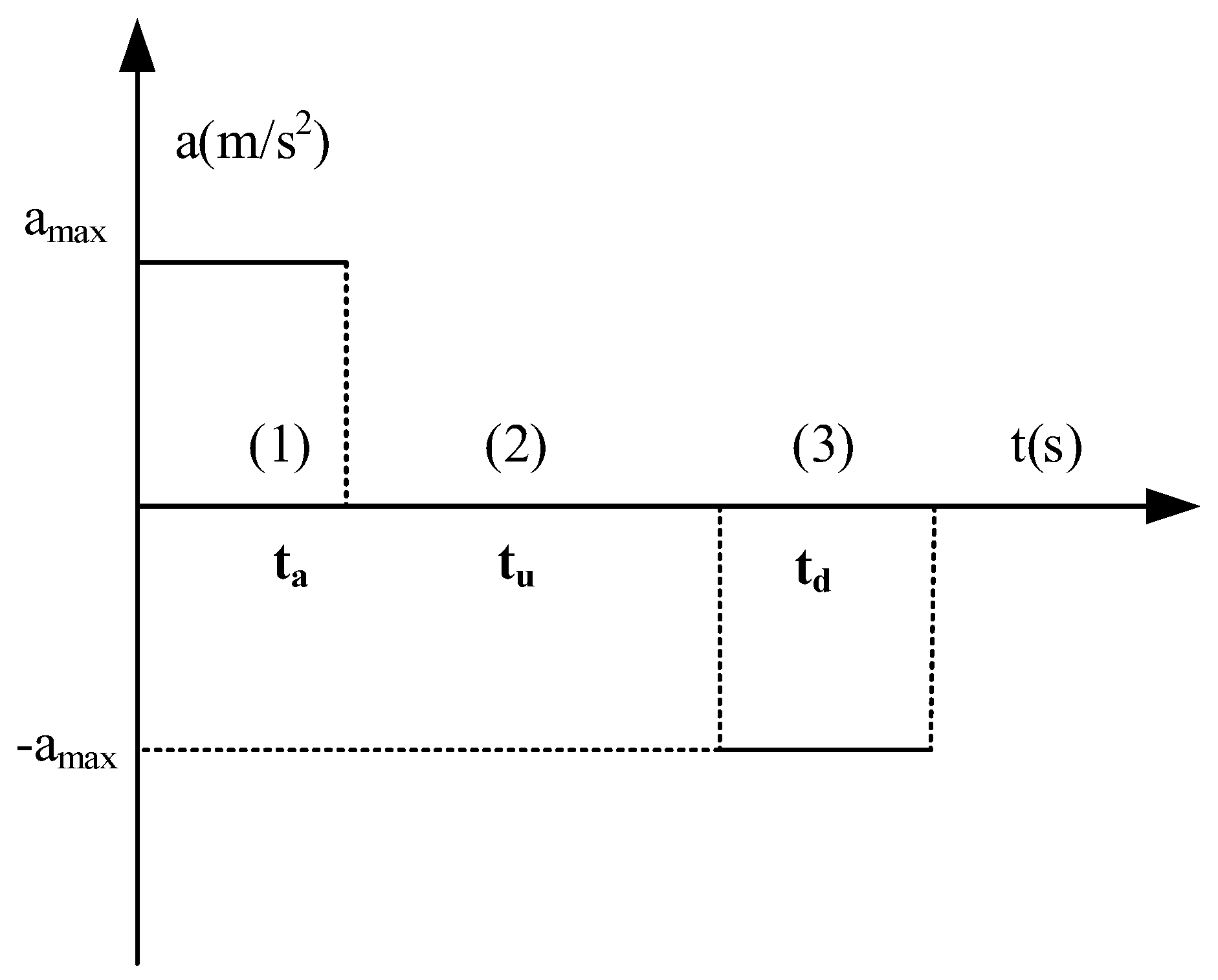
4.1. Modeling of Streamlined Motion Components for Continuous Acceleration/Deceleration of Trolleys

The velocity–time curve of the trolley during continuous acceleration/deceleration is shown in Figure 3 as a trapezoidal curve. According to the relevant design manual, the maximum acceleration (deceleration) speed of the trolley can be taken as 0.67 m/s2, which is much larger than the linear acceleration motion threshold of 0.20 m/s2. At this time, the acceleration (deceleration) time is about 6 s. The corresponding acceleration versus time curve is shown in Figure 9.
According to the design of the streamlined motion blending algorithm, the continuous acceleration and deceleration of the trolley should be directly converted into the tilt motion that can be realized on the motion platform and is equivalent to the motion tactile by the “tilt coordinate method”. If the simulated low-frequency linear accelerations in XOY plane are ax and ay respectively, the corresponding platform inclination angles γ (around Y axis) and β (around X axis) can be expressed as:
γ = arcsin ( a x g ) β = arcsin a y g cos γ
Therefore, the linear acceleration ax of the trolley can be converted to the rotational motion γ. According to the maximum acceleration (deceleration) of the trolley 0.67 m/s2, the corresponding γ is calculated to be about 4°. In order not to allow the human body to perceive rotation but only feel the pushback and forward feeling caused by sustained acceleration/deceleration, it is necessary to make the rotation speed within the human body’s sensory threshold of 3°/s.
If the vehicle is directly accelerated by the maximum acceleration, and the rotation speed is set to 2°/s, the motion curve can be approximated by the following formula:
γ = 2 t           0 < t 2 t 4 °           2 < t < t 1 4 °         2 ( t t 1 ) t 1 < t < t 1 + 2 0               t > t 1 + 2
Among them, t 1 is the time when the acceleration stops.
Thus, the motion curve shown in Figure 9 can be replaced by the equivalent motion curve in Figure 10.

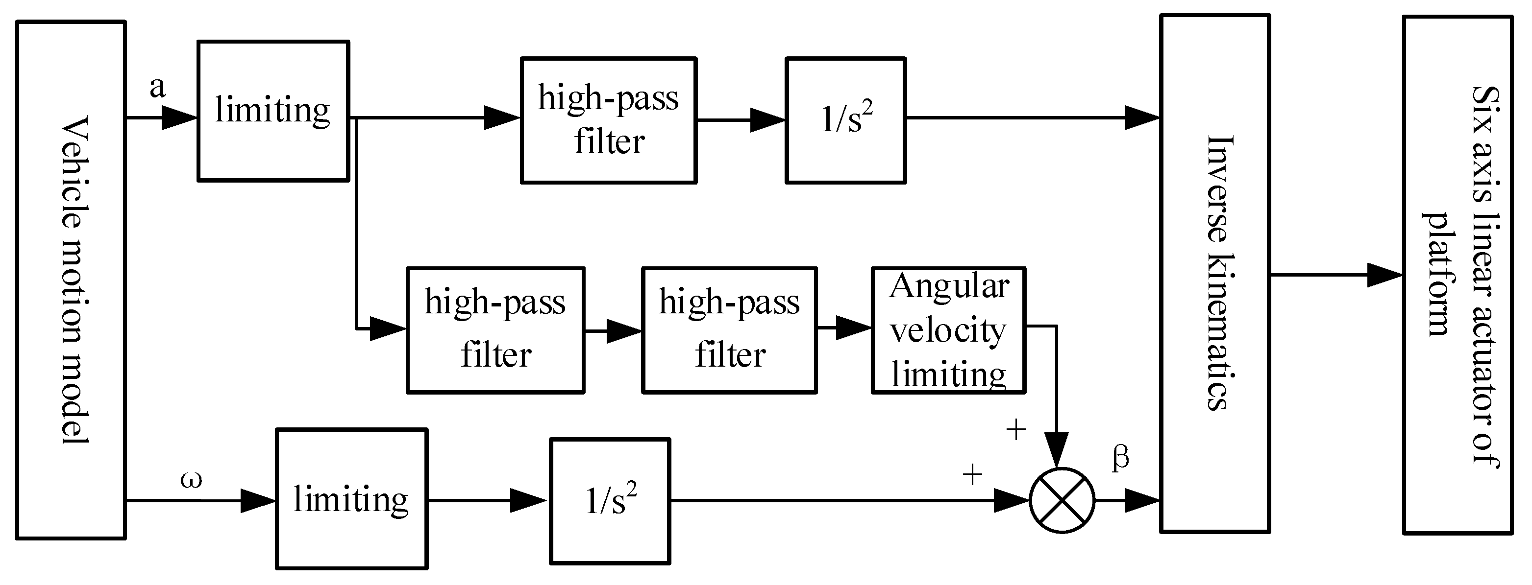
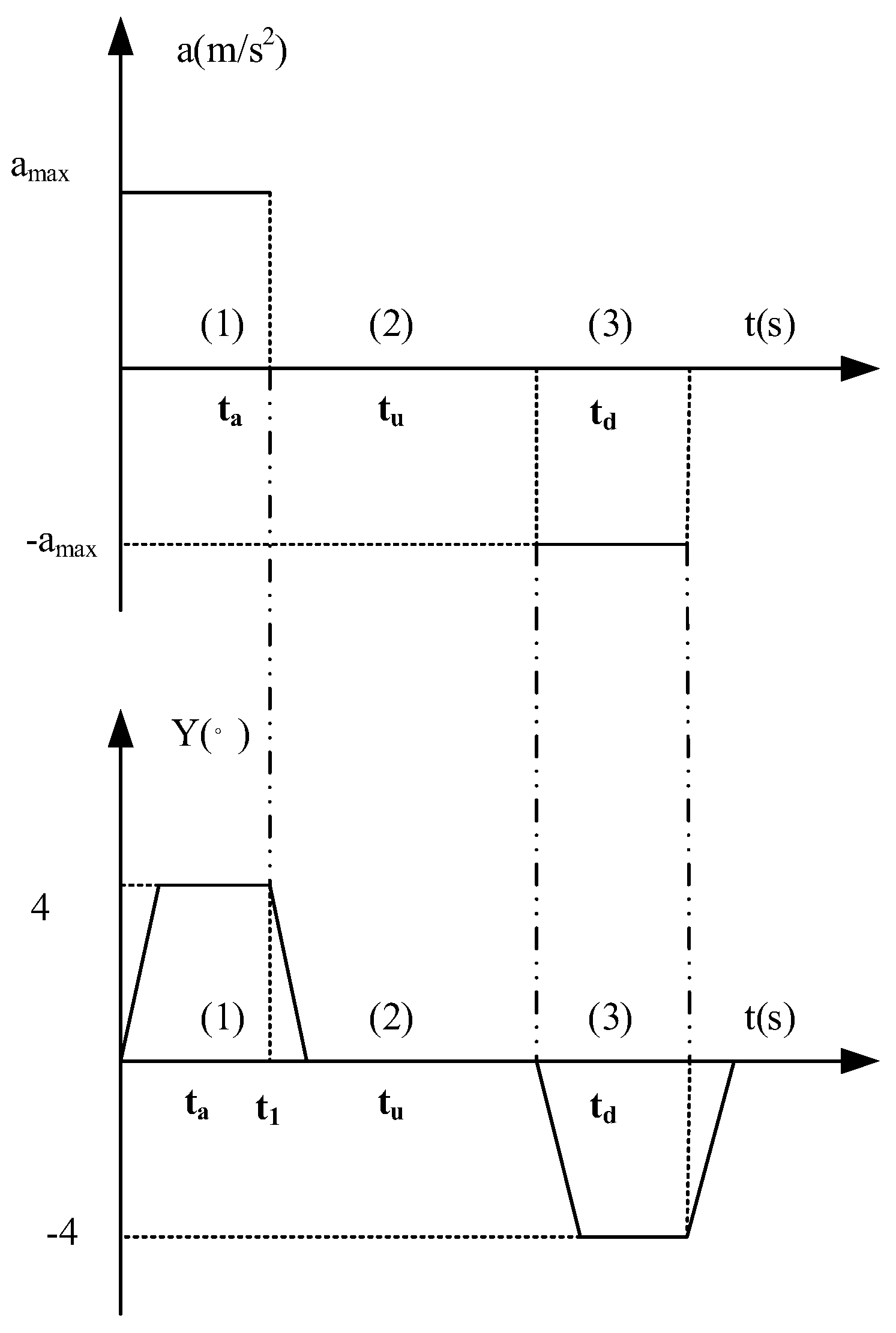
4.2. Modeling of Motion Components Caused by Acceleration/Deceleration Impact of Traveling Mechanism

When the traveling mechanism starts acceleration or deceleration stops, the cab can be regarded as damping vibration according to the natural frequency. Due to the large volume and complex structure of the quayside bridge, it is difficult to calculate the damping vibration in the actual situation. Therefore, the whole quayside bridge is regarded as a whole when the traveling mechanism starts or stops, and is firmly fixed with the ground. The natural frequency is calculated according to the simplified structure, as shown in Figure 11.
The assumption condition for calculating the damping motion formula is that the resistance is proportional to the velocity of motion. This can be expressed as:
f r = γ v = γ d y d t
where γ is the corresponding platform inclination angles (around the y-axis).
Applying Newton ’s second law can be expressed as:
k x γ y · = m y · ·
k m = ω 0 2
γ m = 2 β
y · · + ω 0 2 y · + 2 β y = 0
In general, the vibration is underdamped, the vibration displacement formula can be expressed as:
y ( t ) = A e β t cos ( ω t + φ ) ,   ω = ω 0 2 β 2
where φ = 0 for acceleration and φ = 180 ° for deceleration; the amplitude proportional coefficient A and parameter ω are measured by the actual vibration of the quayside bridge. The amplitude of the acceleration (deceleration) handle at different retaining positions is slightly different, which can be considered according to the situation when the moving block is hit from the empty to the highest grade. The calculation of parameter β needs to simplify the large vehicle into the form of Figure 11, and then estimate the value of k according to the steel-related parameters and the size of the quayside bridge, in order to obtain ω 0 and finally solve β . The trajectory of the vibration curve is shown in Figure 12.
The motion of the traveling mechanism decelerating from the forward gear to the empty gear can be regarded as the same as that of the forward gear.

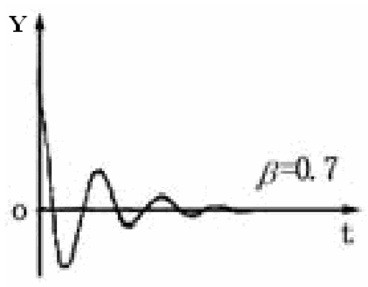
4.3. Modeling of a Special Motion Component

Reset motion is to add an additional motion in addition to the normal motion reproduction algorithm. The purpose is to ensure that the motion simulator performs a reset motion in the absence of human body detection after each violent motion is simulated. If there is no reset motion component, after long-term operation of the motion platform, a variety of small errors will gradually accumulate, resulting in greatly reduced accuracy of motion simulation, and the platform cannot reproduce the desired motion.
In the debugging process of this project, it is found that, if no special reset operation is automatically performed in the process of motion simulation, the normal simulation motion of the platform will collapse after about two hours of continuous work, indicating the importance of regular reset:
(1) The choice of time window for executing reset
Obviously, selecting the appropriate reset time window in the working cycle of the quay crane needs to follow the following principles:
➀ In this time window period, the driver’s room should have basically returned to or very close to the initial equilibrium point.
➁ In addition to random small disturbances such as wind-induced vibration, the actual motion of the cab in the virtual world should be able to maintain a relatively static or uniform forward state for a long time during the selected reset time window.
According to the above principles, the final reset time window is: the time period during which the trolley moves from the sea side to the land side, passes through the rail gap between the front girder and the rear girder for a certain distance, remains stationary, and the spreader descends, that is, section B-A in Figure 2. At this time, the trolley is located in the shore bridge portal frame with large stiffness, and the vibration caused by the previous crossing rail joints has been attenuated. Therefore, in addition to the weak random vibration, the driver’s room is almost static, and the duration of this time period is long, about 5 seconds. According to experience, the time required for the simulation platform to reset without notice is not more than 1 second.
(2) Reset algorithm
For the reset time window selected in the motion simulation of the crane studied in this paper, the reset we need is based on the reset function of the classical washout algorithm, which is more thorough in the physical layer of the terminal. The algorithm is simpler and faster, which can eliminate the motion drift caused by the cumulative error.
The steps of the algorithm are:
STEP1: Stop all other motion components and obtain complete control of the motion platform;
STEP2: Obtain the elongation of six electric cylinders by encoder, which are expressed as l 1 ,   l 2 ,   l 3 ,   l 4 ,   l 5 ,   l 6 ;
STEP3: Compare with the reference electric cylinder elongation L 10 ,   L 20 ,   L 30 ,   L 40 ,   L 50 ,   L 60 of the initial equilibrium point of the platform, and calculate the difference { Δ l 1 , Δ l 2 , Δ l 3 , Δ l 4 , Δ l 5 , Δ l 6 }
STEP4: Take the reset running time for 1 second, let the electric cylinder complete the calculation of { Δ l 1 , Δ l 2 , Δ l 3 , Δ l 4 , Δ l 5 , Δ l 6 } in 1 second.
This reset algorithm is also a streamlined reset algorithm without intermediate links. Overall, if the reset motion is also treated as a motion component controlled by a motion model, the details of the model are:
The symbol of motion component model: ResetPlatform;
The main content of the model: Complete STEP 1 to STEP 4 operation;
Triggering condition: The trolley runs from the sea side to the land side to point B shown in Figure 2;
Exit condition: Automatic exit.

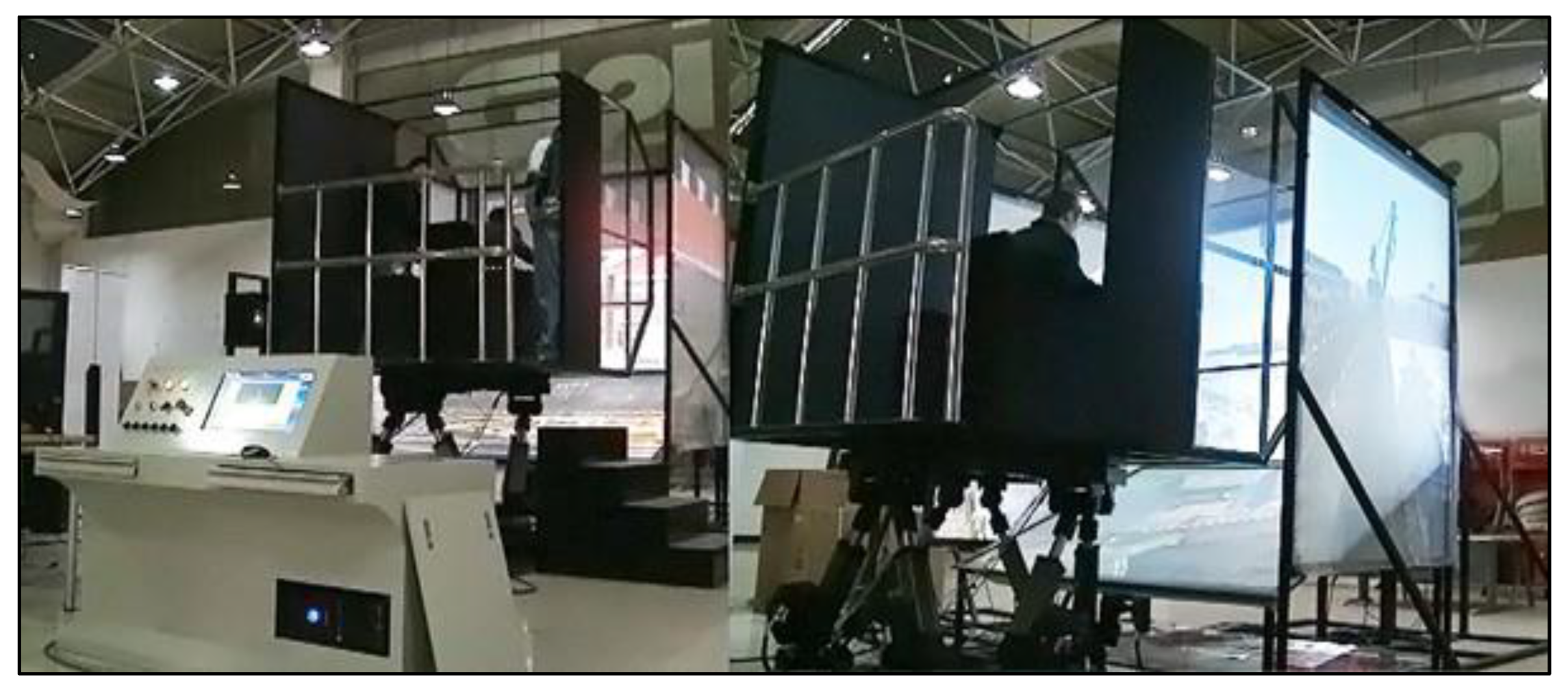
5. Implementation and Evaluation

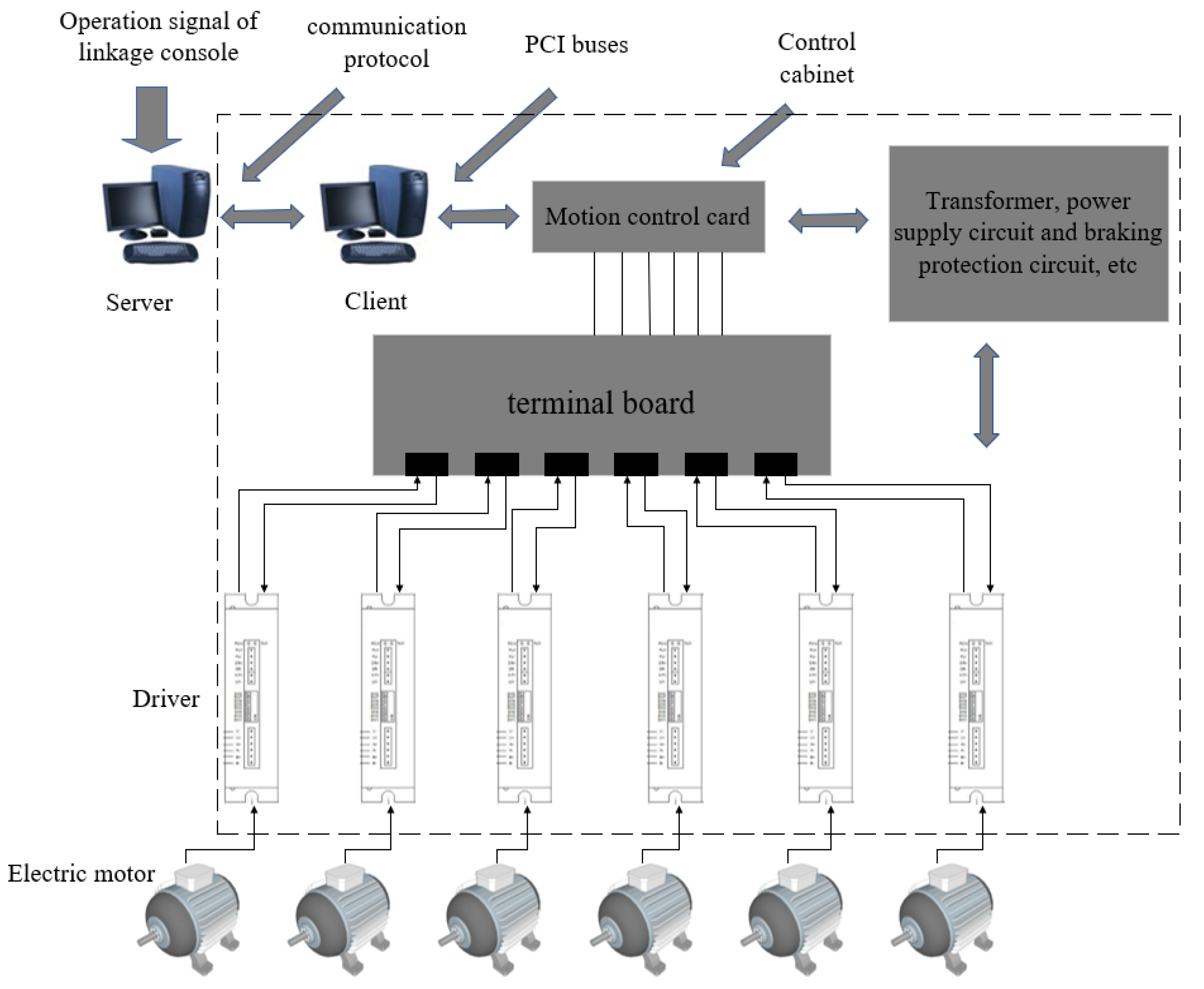
5.1. System Implementation

During the system implementation, the hardware composition of the system is shown in Figure 13. The parts in the dashed box are installed in the control cabinet, and the other parts are outside. Its main body is a six-degree-of-freedom motion platform driven by an electric cylinder, and its key components include motion control cards, servo drives, and motors. The computer system is divided into server and client levels. The client converts the six degrees of freedom motion information of the platform task space into the motion information of the joint space of the six electric cylinders, and then transmits it to the motion control card, which is passed to the servo drive to drive the motor to move according to the required trajectory.
The real-time control flow of the motion control system is shown in Figure 14, which ensures that, when the trainee manipulates the crane, the system can automatically provide the corresponding motion feeling according to the control signal of the linkage table and coordinate with other simulation subsystems such as the scene. The server completes the generation or exit of the response curve of each independent motion component, and notifies the client through the network. The client first completes the fusion of each motion curve, and then discrete, according to its own rhythm to promote the motion platform. The discrete motion curve can be transformed into the variation of the elongation of each motion cylinder of the 6-DOF motion platform through the inverse solution algorithm of motion attitude.
Figure 15 shows the physical scene of the finally developed crane operation training simulator. On the left side is the motion control computer as the client, and on the right side is the motion platform integrated with the visual display system.

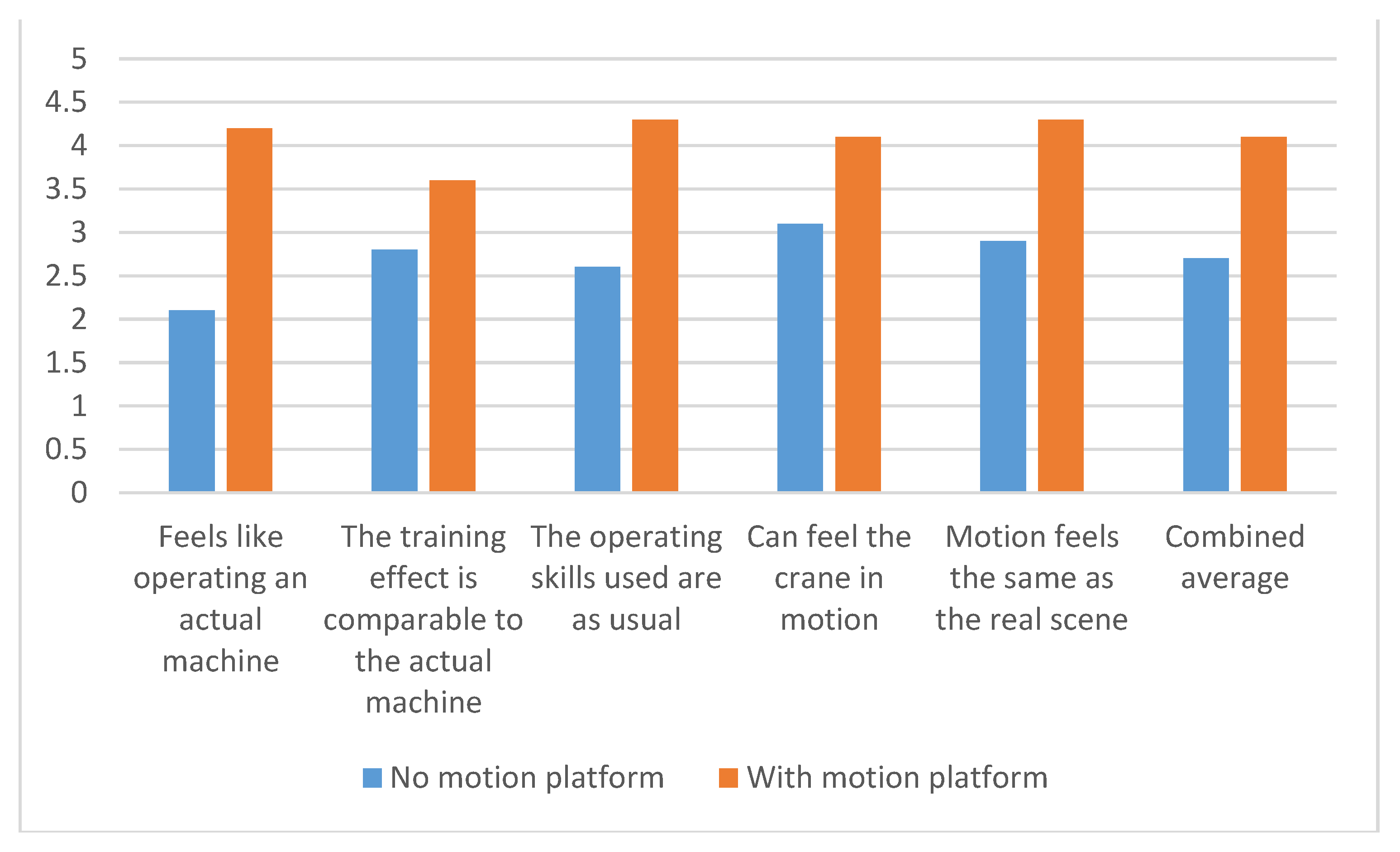
5.2. Application Effect Evaluation

Since motion is a performance that cannot be accurately measured, the effectiveness of the motion simulation system can only be evaluated by the subjective feelings of the system users. After the successful development of this system, it has experienced two stages of performance evaluation:
The first stage is an open and uncontrolled subjective evaluation. The personnel involved in the evaluation include the personnel of the project research team and the crane driver who voluntarily participate in the evaluation, who have a deep understanding of the system function, and most of them are positive evaluations.
The second stage is completely controlled subjective evaluation. Several old drivers with rich practical experience but never having used a crane training simulator are invited to participate in the test operation, and then a questionnaire survey is carried out. The design of the questionnaire refers to the literature. Finally, the motion simulation performance of the system is evaluated according to the results of the questionnaire survey.
A total of seven drivers were invited in the experiment, all of whom were males with an average age of 38, and the average driving age for quay cranes was 16 years. The test steps are as follows: firstly, the driver completes the operation cycle defined in Section 2 on the crane virtual simulation training platform without motion simulation platform. At this time, the driver can only rely on the auxiliary training function provided by the visual system and the analog audio system. Then, for the same work cycle, open the visual system, sound simulation system, and motion simulation system. Finally, let the driver make a subjective evaluation of the training effect; the most important thing in the evaluation is the introduction of motion simulation platform to improve the training effect. The evaluation questionnaire contains five statements, and the scoring benchmark is based on the standardized Likert scale, with 1 point strongly disagreeing; 5 points means strong column consent, equivalent to the score according to the feeling of operation on the real crane.
Table 3 shows the average score of each statement in the questionnaire collected after the completion of the controlled subjective evaluation test. Figure 16 is the corresponding histogram. To evaluate the training effectiveness of the crane simulator, define a comprehensive training effectiveness index for measurement for the condition in which the comprehensive training effectiveness index is set to 100% when the trainees are trained on the real crane. It can be seen from Table 3 and Figure 16 that, according to the simple comprehensive average estimation, the comprehensive training effectiveness index of the crane simulator can reach 54 % (2.7/5) if the simulator excludes any motion simulation system and only relies on the visual system and the acoustic effect system. As a comparison, once the motion simulation system is added, the comprehensive training effectiveness index can be improved to 82% (4.1/5). Such experimental data show that the subjects also have a certain sense of motion without the motion simulation system and only depending on the visual system and acoustic effect system, but once the motion simulation system is introduced, the subjects’ sense of motion has been significantly improved, resulting in a significant improvement in the comprehensive training effect.

6. Conclusions

In this paper, a motion generation approach for a crane simulator is proposed based on streamlined motion blending technology. This approach incorporates the characteristics of the perceptible motion of a crane, which are decomposed into two types of motion components, i.e., high-frequency small-scale vibrations and low-frequency large-scale movements. At the moment when each motion component constituting the motion is generated, it is directedly modeled or modeled with an immediate conversion applied. Specifically, for the motion component of high-frequency small-scale vibrations, it is modeled according to crane dynamics and remains unchanged without the need for motion washout processing. For the motion component of low-frequency large-scale movements, the real motion mode is firstly defined and then immediately converted into another equivalent motion component according to the principle of the motion washout algorithm. After the motion components are identified and handled adequately in this way, they are then blended together to form a coherent motion stream to drive the platform. The effect of the motion generation algorithm based on this approach is exactly the same as the processing method deduced according to the existing motion blending technology combined with the classical washout algorithm. However, the current algorithm eliminates multiple redundant filtering tasks, and thus is more efficient and smoother. The computational workload is greatly reduced, and the real-time performance is stronger.
By taking a concrete motion simulator of the quayside bridge crane as an example, the proposed motion generation approach based on the streamlined motion blending technology is implemented in detail. The general algorithm design of the complete motion perception simulation system, as well as the modeling of each motion component, is carried out. Related decisions are considerately made to select the appropriate motion platform and other hardware facilities. Apart from the motion generation system, the prototype system developed also includes a visual system. An experimental verification study is conducted by inviting skilled driver volunteers. The experimental results show that the developed prototype system has high motion fidelity, and this high-fidelity motion performance helps to improve the training effect of the simulator in training new crane drivers.
The crane motion simulation method based on streamlined motion blending technology has a wide range of generality. It is not only suitable for the quayside container bridge crane simulator as an application example in this paper, but is also suitable for other types of cranes and various construction machinery. Once the motion simulation method proposed in this paper is extended to other engineering machinery simulators, the corresponding models and algorithms can be developed accordingly. It is finally expected to provide trainees with a more realistic motion perception effect in this way and thus create more application value.

Author Contributions

Conceptualization, Z.Z., Y.L., H.X. and G.W.; methodology, Z.Z. and G.W.; software, Z.Z. and G.W.; validation, Z.Z., Y.L., H.X., Z.L., C.X. and G.W.; formal analysis, Z.Z. and Y.L.; investigation, Z.Z. and Y.L.; resources, Z.Z., Y.L., H.X. and G.W.; data curation, Z.Z. and Y.L.; writing—original draft preparation, Z.Z., H.X. and G.W.; writing—review and editing, Z.Z., Y.L., H.X., Z.L., C.X. and G.W.; visualization, Z.Z. and G.W.; supervision, Z.Z., Y.L., H.X., Z.L., C.X. and G.W.; project administration, Z.Z., Y.L., H.X., Z.L., C.X. and G.W.; funding acquisition, Z.Z., Y.L., H.X., Z.L., C.X. and G.W. All authors have read and agreed to the published version of the manuscript.

Funding

This research received no external funding.

Institutional Review Board Statement

Not applicable.

Informed Consent Statement

Not applicable.

Data Availability Statement

Data are contained within the article.

Conflicts of Interest

The authors declare no conflict of interest.

References

  1. Kang, S.; Lee, S.; Choo, Y. Development of a Remote Operation System for a Quay Crane Simulator. J. Inst. Control Robot. Syst. 2015, 21, 385–390. [Google Scholar] [CrossRef]
  2. Rouvinen, A.; Lehtinen, T.; Korkealaakso, P. Container Gantry Crane Simulator for Operator Training. Proc. Inst. Mech. Eng. Part K J. Multi-Body Dyn. 2005, 219, 325–336. [Google Scholar] [CrossRef]
  3. Juang, J.R.; Hung, W.H.; Kang, S.C. SimCrane 3D(+): A crane simulator with kinesthetic and stereoscopic vision. Adv. Eng. Inform. 2013, 27, 506–518. [Google Scholar] [CrossRef]
  4. Lu, K.-L.; Mi, W.-J.; Jiang, M.-M.; Liu, Y.-B. Real-time simulation dynamics model and solution algorithm for the trolley-hoisting system in container crane simulated training system. J. Vibroenginerring 2016, 18, 1254–1269. [Google Scholar]
  5. Guo, X.; Song, Q. Research on Modeling and Simulation Techniques of Electromechanical Integration Based on Virtual Prototype. Agro Food Ind. Hi-Tech 2017, 28, 2303–2306. [Google Scholar]
  6. Jin, Z.; Gao, F.; Li, H.; Li, J. Research of Reliability Enhancement Testing about Wear Failure Component Based on Virtual Prototype Technology. In Proceedings of the 8th International Conference on Management and Computer Science (ICMCS), Shenyang, China, 10–12 August 2018; Atlantis Press: Dordrecht, The Netherlands, 2018; pp. 83–88. [Google Scholar]
  7. Fang, Z.; Zhang, H. Digital Design Technology and Its Application of Servo Device. In Proceedings of the 3rd World Conference on Mechanical Engineering and Intelligent Manufacturing (WCMEIM), Shanghai, China, 4–6 December 2020; IEEE: Piscataway, NJ, USA, 2020; pp. 487–491. [Google Scholar]
  8. Xiao, X.; Joshi, S. Decomposition and Sequencing for a 5-Axis Hybrid Manufacturing Process. In Proceedings of the ASME 2020 15th International Manufacturing Science and Engineering Conference, Virtual, 3 September 2020. [Google Scholar]
  9. Xiao, X.; Joshi, S. Process planning for five-axis support free additive manufacturing. Addit. Manuf. 2020, 36, 101569. [Google Scholar] [CrossRef]
  10. Song, S.; Yang, J. Configurable component framework supporting motion platform-based VR simulators. J. Mech. Sci. Technol. 2017, 31, 2985–2996. [Google Scholar] [CrossRef]
  11. Lu, H.; Zhen, H.; Huang, Y.; Guo, G. Motion Platform Designed for Container Crane Simulator. Int. J. Control Autom. 2016, 9, 97–104. [Google Scholar] [CrossRef]
  12. Xiao, X.; Joshi, S. Automatic Toolpath Generation for Heterogeneous Objects Manufactured by Directed Energy Deposition Additive Manufacturing Process. J. Manuf. Sci. Eng.-Trans. ASME 2018, 140, 071005. [Google Scholar] [CrossRef]
  13. Xiao, X.; Waddell, C.; Hamilton, C.; Xiao, H. Quality Prediction and Control in Wire Arc Additive Manufacturing via Novel Machine Learning Framework. Micromachines 2022, 13, 137. [Google Scholar] [CrossRef] [PubMed]
  14. Fang, Z.; Tsushima, M.; Kitahara, E.; Machida, N.; Wautier, D.; Kemeny, A. Motion cueing algorithm for high performance driving simulator using yaw table. In Proceedings of the 20th World Congress of the International-Federation-of-Automatic-Control (IFAC), Toulouse, France, 9–14 July 2017; Elsevier: Amsterdam, The Netherlands, 2017; pp. 15965–15970. [Google Scholar]
  15. Ming-Yen, W. Design of a DSP-Based Motion-Cueing Algorithm Using the Kinematic Solution for the 6-DoF Motion Platform. Aerospace 2022, 9, 203. [Google Scholar]
  16. Pham, D.-A.; Nguyen, D.-T. A novel motion cueing algorithm integrated multi-sensory system-Vestibular and proprioceptive system. Proc. Inst. Mech. Eng. Part K J. Multi-Body Dyn. 2020, 234, 256–271. [Google Scholar]
  17. Zou, S.; Pang, L.; Xu, C.; Xiao, X. Effect of Process Parameters on Distortions Based on the Quantitative Model in the SLM Process. Appl. Sci.-Basel 2022, 12, 1567. [Google Scholar] [CrossRef]
  18. Colombet, F.; Fang, Z.; Kemeny, A. Tilt thresholds for acceleration rendering in driving simulation. Simul.-Trans. Soc. Model. Simul. Int. 2017, 93, 595–603. [Google Scholar] [CrossRef]
  19. Bae, J.; Cha, J.; Seo, M.-G.; Lee, K.; Lee, J.; Ku, N. Experimental Study on Development of Mooring Simulator for Multi Floating Cranes. J. Mar. Sci. Eng. 2021, 9, 344. [Google Scholar] [CrossRef]
  20. Chen, N.; Liu, X.; Li, R.; Zheng, X.; Chen, S.; Zhang, H. Applied in Crane Simulator Based on the Fuzzy Control Washout Algorithm. In Proceedings of the 37th Chinese Control. Conference (CCC), Wuhan, China, 25–27 July 2018; pp. 2106–2110. [Google Scholar]
  21. Landsverk, R.; Zhou, J. Modeling and Simulation of an Offshore Crane. In Proceedings of the 13th IEEE Conference on Industrial Electronics and Applications (ICIEA, Wuhan, China, 31 May–2 June 2018; pp. 713–718. [Google Scholar]
  22. Masullo, M.; Pascale, A.; Toma, R.A.; Ruggiero, G.; Maffei, L. Virtual Reality Overhead Crane Simulator. In Proceedings of the 3rd International Conference on Industry 4.0 and Smart Manufacturing (ISM), Linz, Austria, 2–4 November 2022; pp. 205–215. [Google Scholar]
  23. Noda, Y.; Hoshi, R.; Kaneshige, A. Training Simulator for Acquiring Operational Skill to Operate Overhead Traveling Crane while Suppressing Load Sway. Shock Vib. 2019, 2019, 3060457. [Google Scholar] [CrossRef]
  24. Cha, M.; Yang, J.; Han, S. An interactive data-driven driving simulator using motion blending. Comput. Ind. 2008, 59, 520–531. [Google Scholar] [CrossRef]
  25. Cha, M.; Yang, J.; Han, S. A Hybrid Driving Simulator with Dynamics-Driven Motion and Data-Driven Motion. Simul.-Trans. Soc. Model. Simul. Int. 2008, 84, 359–371. [Google Scholar] [CrossRef]
Figure 1. Coordinate system of crane cab and motion platform: (a) quayside container crane coordinate system; (b) coordinate system of the 6-DOF motion platform.
Applsci 12 08799 g001
Figure 2. Periodicity of quay cranes’ operation process.
Applsci 12 08799 g002
Figure 3. Velocity curve of low frequency motion.
Applsci 12 08799 g003
Figure 4. Classical washout algorithm.
Applsci 12 08799 g004
Figure 5. Motion blending technology in the trolley driving simulator.
Applsci 12 08799 g005
Figure 6. Crane motion simulation based on motion blending technology.
Applsci 12 08799 g006
Figure 7. Motion simulation of crane based on streamlined motion blending technology.
Applsci 12 08799 g007
Figure 8. Algorithm flow of motion simulation based on streamlined motion blending.
Applsci 12 08799 g008
Figure 9. Acceleration curve of trolley during continuous acceleration / deceleration movement.
Applsci 12 08799 g009
Figure 10. Equivalent conversion of trolley motion curve.
Applsci 12 08799 g010
Figure 11. Simplified mechanical model of quayside bridge crane.
Applsci 12 08799 g011
Figure 12. Underdamped vibration curve of traveling mechanism acceleration.
Applsci 12 08799 g012
Figure 13. Hardware composition of the 6-DOF motion control system.
Applsci 12 08799 g013
Figure 14. Real-time control flow of the motion control system.
Applsci 12 08799 g014
Figure 15. Physical scene of the crane simulation training system.
Applsci 12 08799 g015
Figure 16. Column chart of controlled subjective evaluation test results.
Applsci 12 08799 g016
Table 1. Improved scale table based on cloud model.
Classification NumberCategoriesTrigger ConditionsEnd ConditionsDirection Involved
Case1Grab BoxesPanel button = Spreader latch
Right hand handle pushed back
Auto EndZ
Case2Placement boxesPanel button = Spreader unlock
Push the right-hand handle forward to stop
Auto EndZ
Case3Trolley accelerationLeft handle from neutral to forward or backward pushReach the maximumX
Case4Trolley decelerationThe left handle is pushed from the front or back to return to the neutral positionSpeed reduced to 0X
Case5Through the rail seamThe front wheels of the trolley reach the rail seam positionAuto EndX
β
Case6Traveling mechanism accelerationRight-hand handle from neutral to forward or backward pushAuto EndY
Case7Traveling mechanism decelerationThe right-hand handle is pushed forward or backward to return to the neutral positionAuto EndY
Case8Boom pitchPanel button = Boom pitchAuto EndX, Y and Z
Case9Wind-induced vibrationProgram setting triggerEnd of program settingAll directions
Table 2. Comparison of existing motion blending techniques and streamlined motion blending techniques in motion simulation.
Comparative ProjectsExisting Motion Blending TechniquesStreamlined Motion Blending Techniques
Applicable objectVehicle driving simulatorCrane simulator
Motion decomposition methodData collection and segmentationModeling by physical subprocess
Digital form of motion elementData fragment in databaseFormula model
Motion blending execution modeCalled by databaseCalled by subprogram block
The output results after blendingThe real movement of automobile in the virtual worldThe real movement of crane in the virtual world can be realized by the moving platform
The conditions for the trigger call of the motion elementScene setting and real-time interactive actionScene setting and real-time interactive action
The way of motion blendingLinear superposition by coordinate component alignmentLinear superposition by coordinate component alignment
Technical development content1. Collecting large amounts of motion data through experiments
2. Deep processing of collected data
1. Dynamic analysis and modeling.
2. Validation of the established model
Program complexityComplicationEdulcorate
Real timeGeneralExcellent
Programming difficulty levelRather difficultSimple
Level of occupancy of computing resourcesOccupying more and requiring database system supportLess occupied and no database system support required
Table 3. Controlled subjective evaluation test results.
Average of the 5 Statements to Be TestedNo Motion PlatformWith Motion Platform
Feels like operating an actual machine2.14.2
The training effect is comparable to the actual machine2.83.6
The operating skills used are as usual2.64.3
Can feel the crane in motion3.14.1
Motion feels the same as the real scene2.94.3
Combined average2.74.1
Publisher’s Note: MDPI stays neutral with regard to jurisdictional claims in published maps and institutional affiliations.

