
Plasma-Sprayed Flexible Strain Sensor and Its Applications in Boxing Glove

 ,
,
Abstract
:1. Introduction
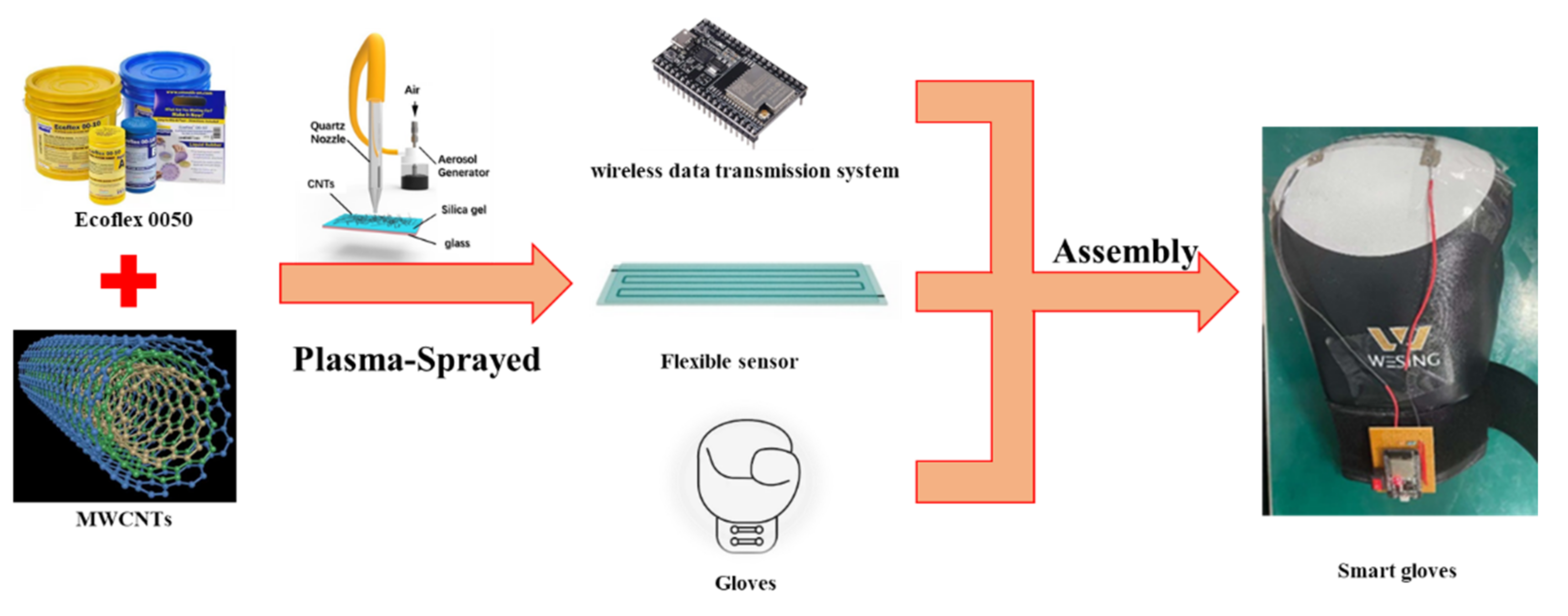
2. The Controllable Plasma Spraying Method for Conducting Nanoparticles
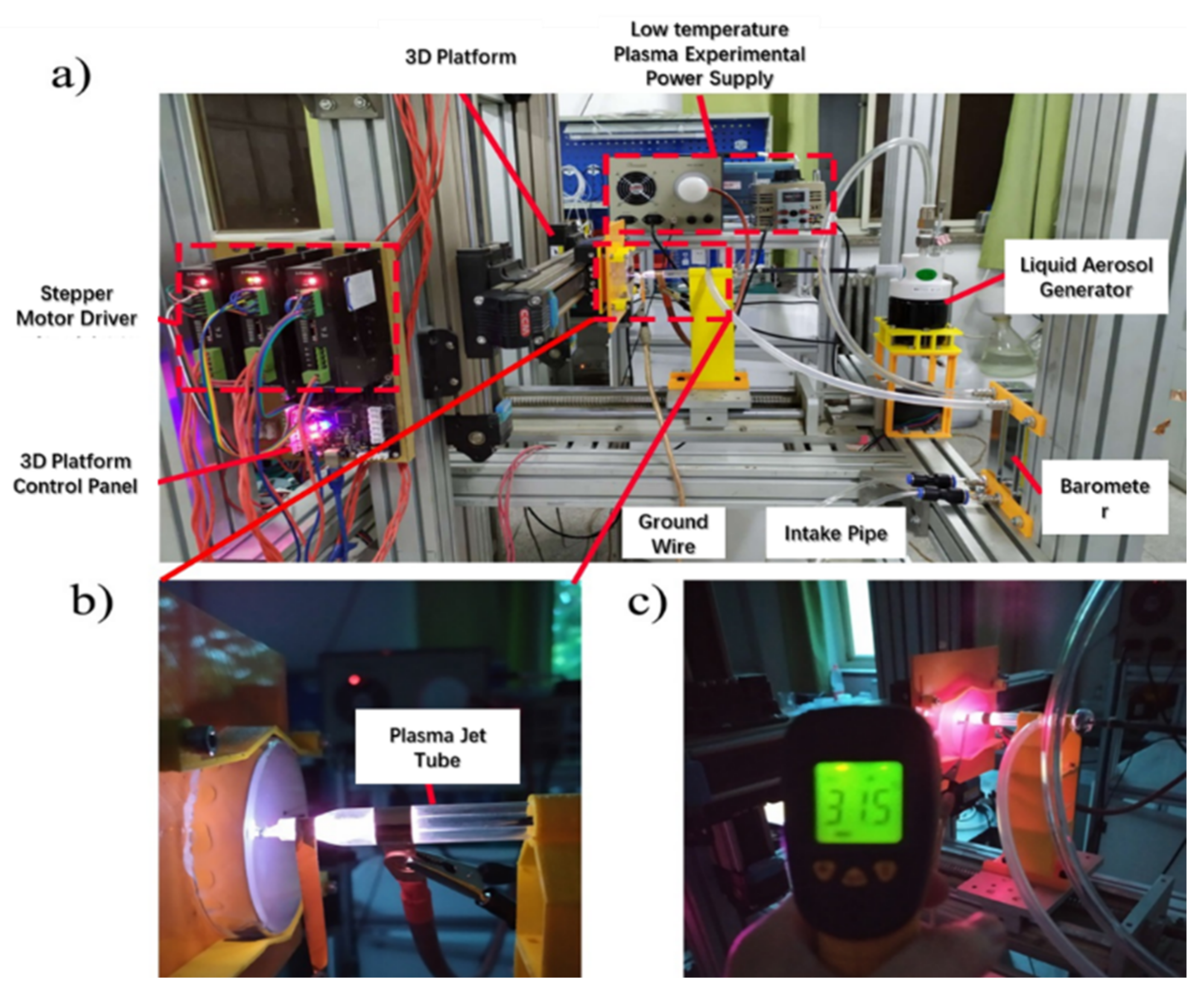
2.1. Low-Temperature-Plasma Spraying Method and Device
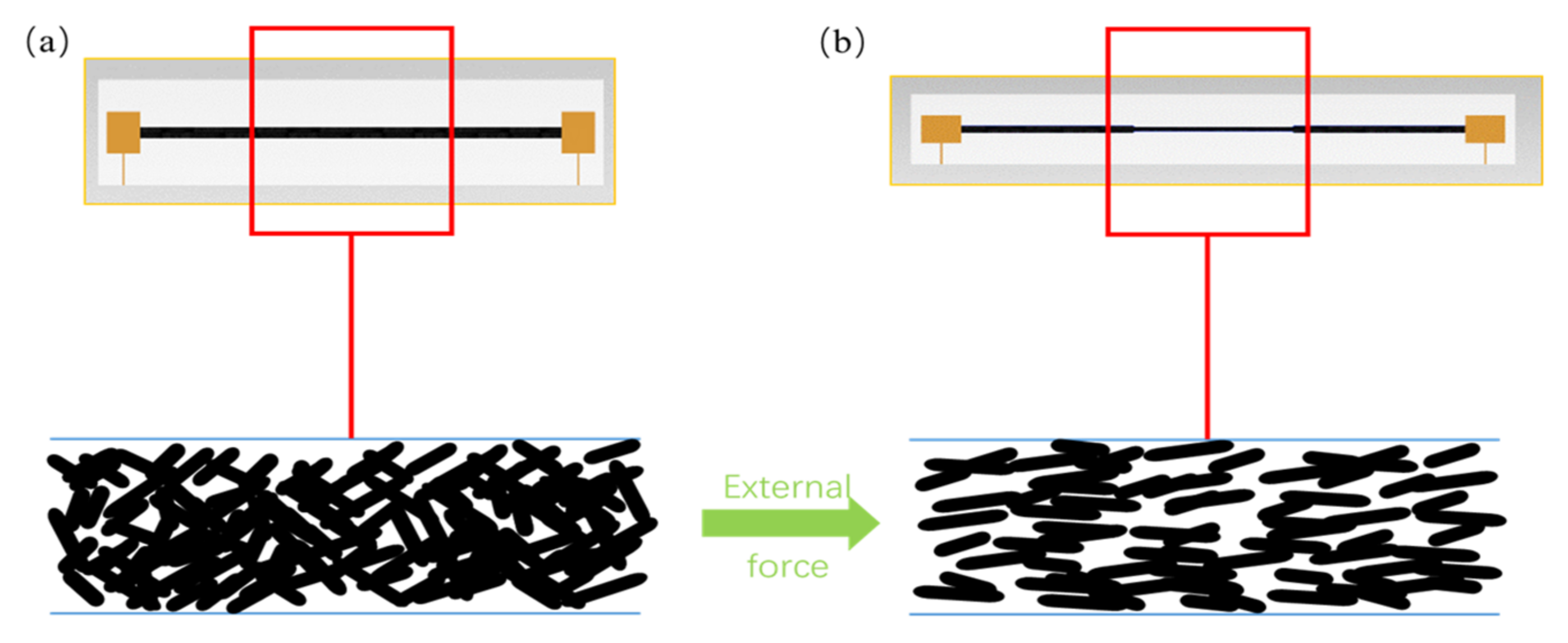
2.2. Mechanism of the Low-Temperature-Plasma Treatment
3. Materials, Manufacturing, and Testing
3.1. Experimental Materials and Equipment
3.1.1. Experimental Materials
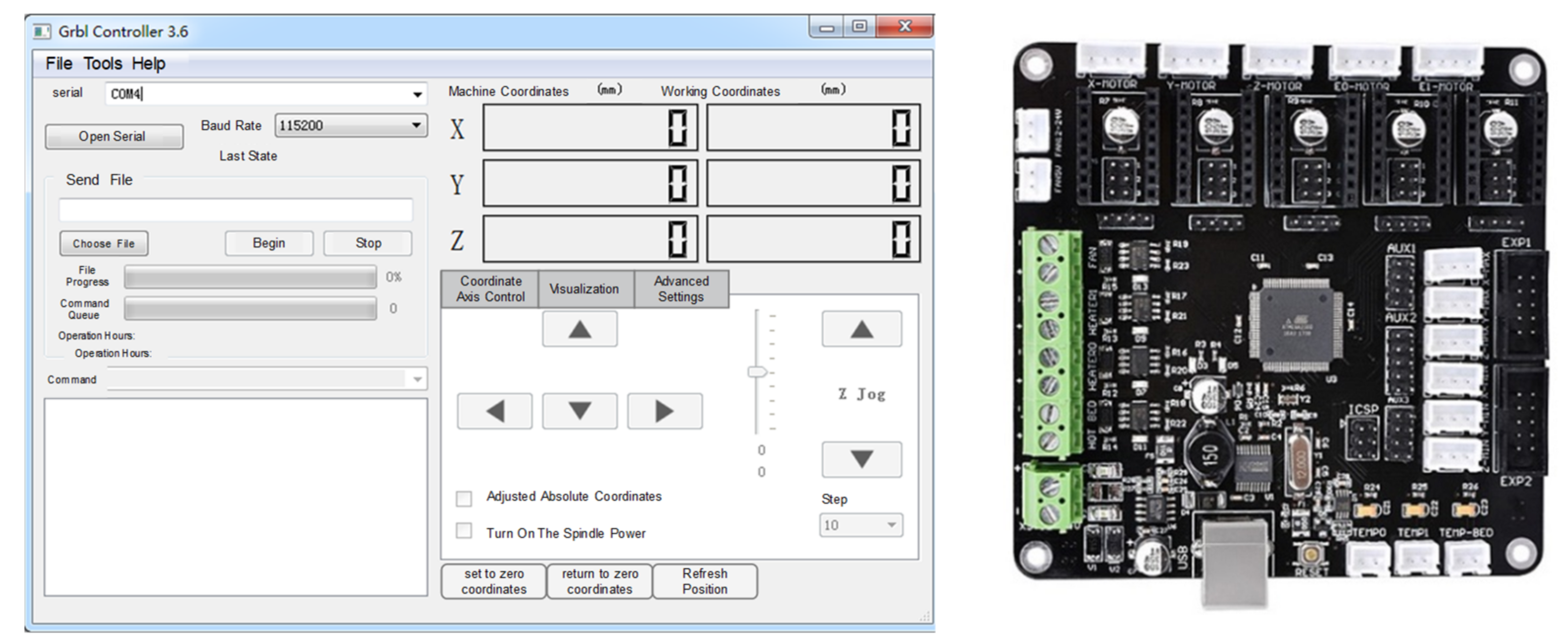
3.1.2. Experimental Equipment
3.2. Manufacturing
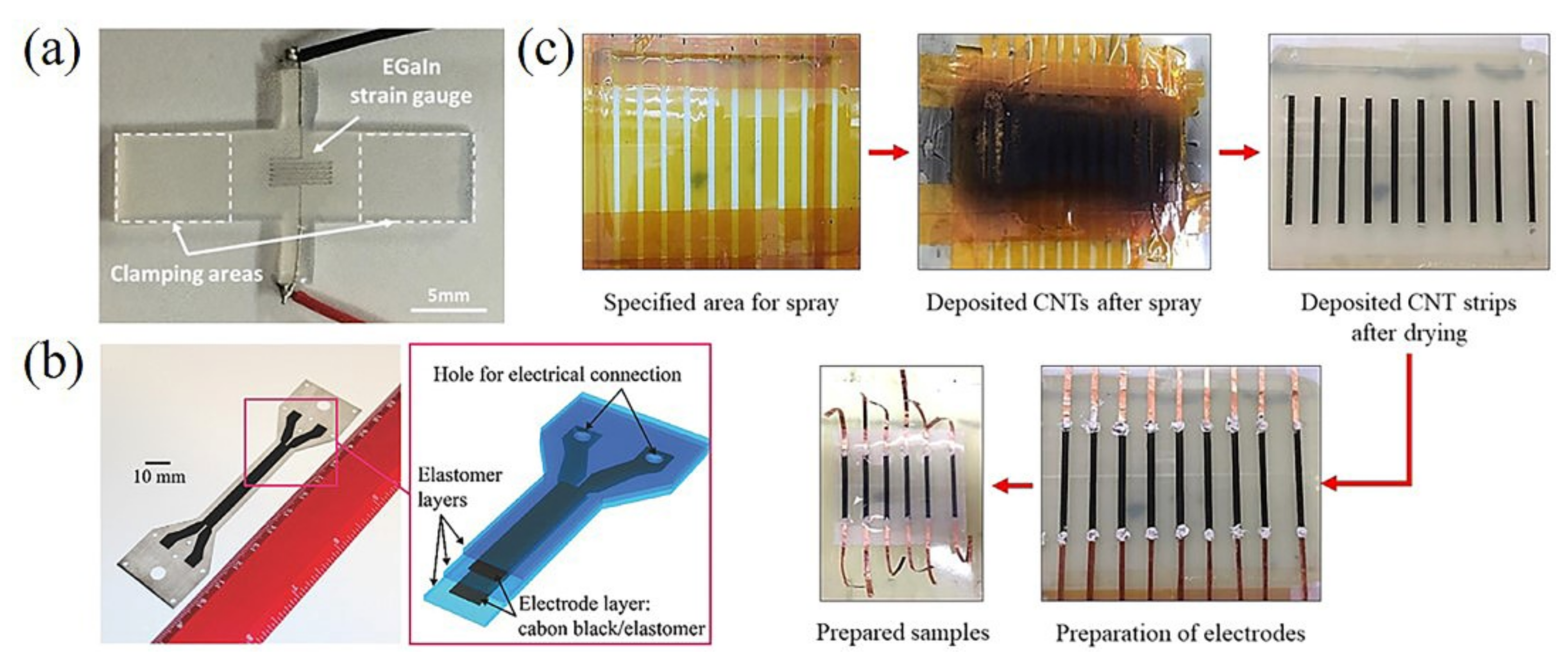
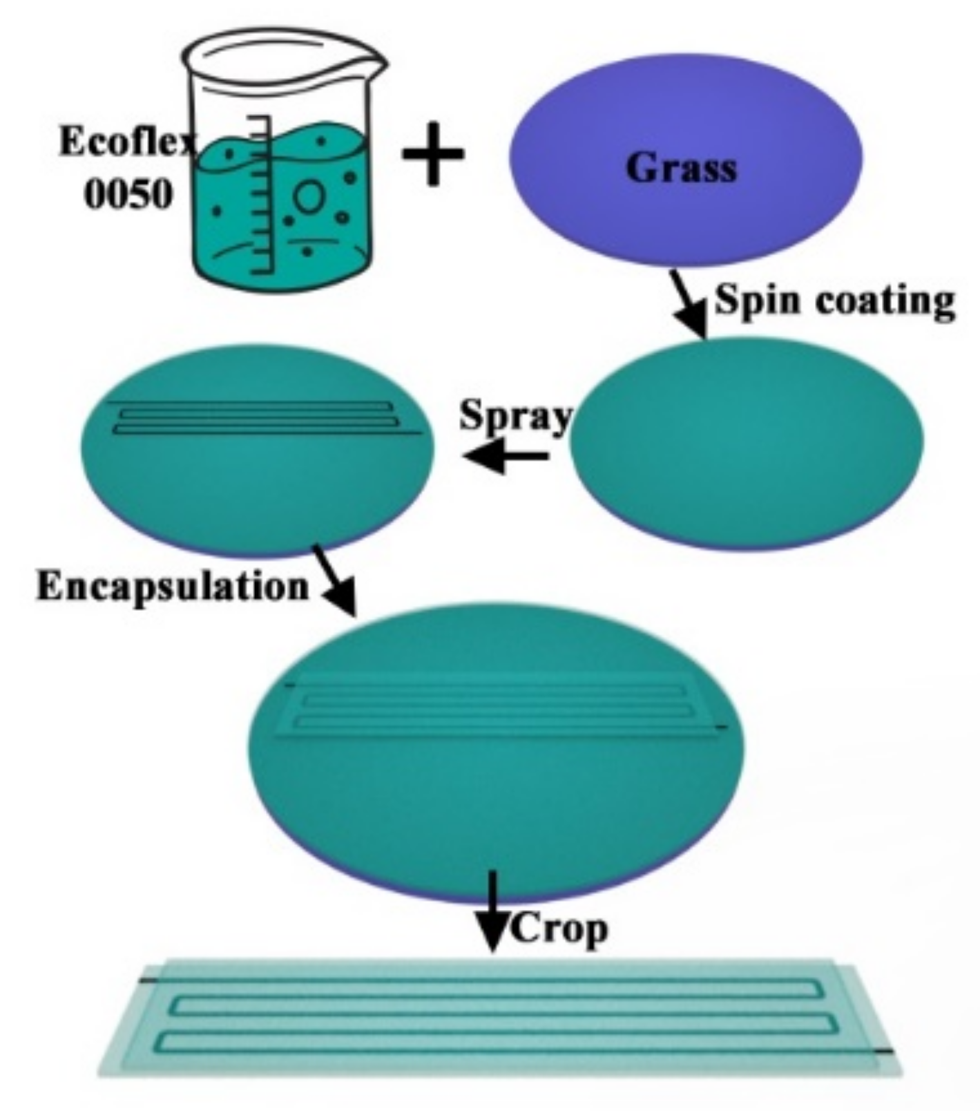
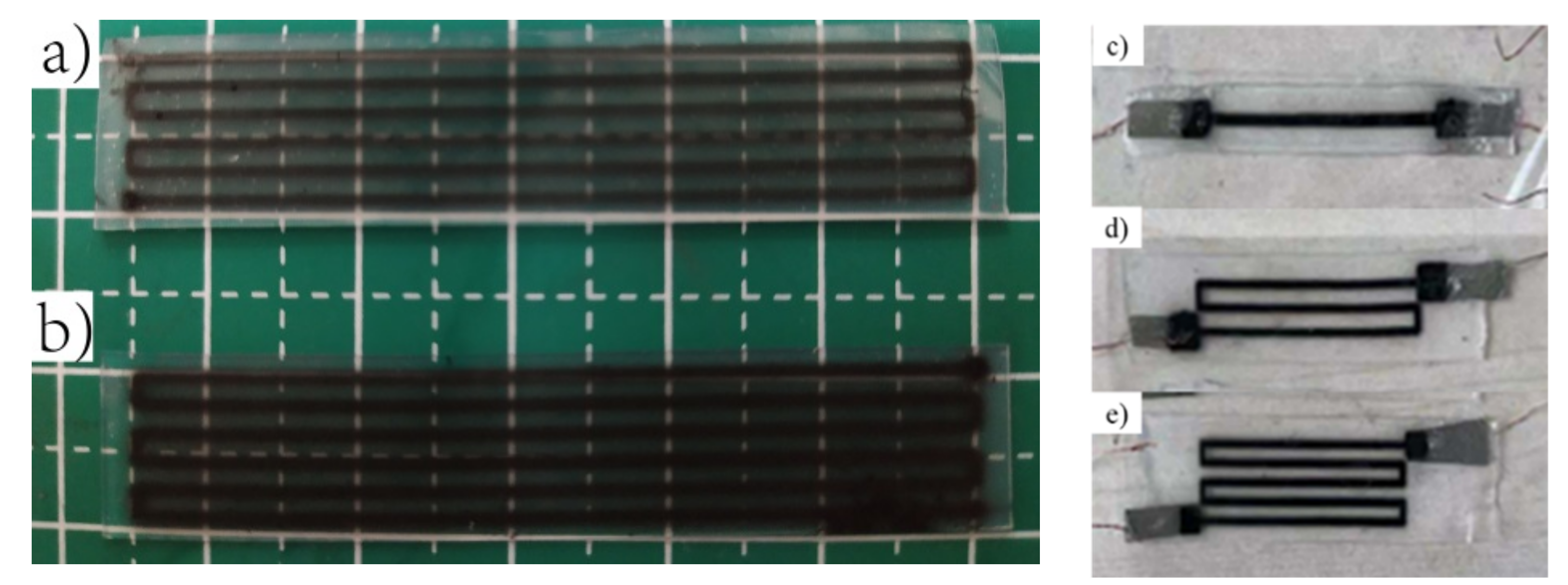
3.2.1. Fabrication of Flexible Sensors
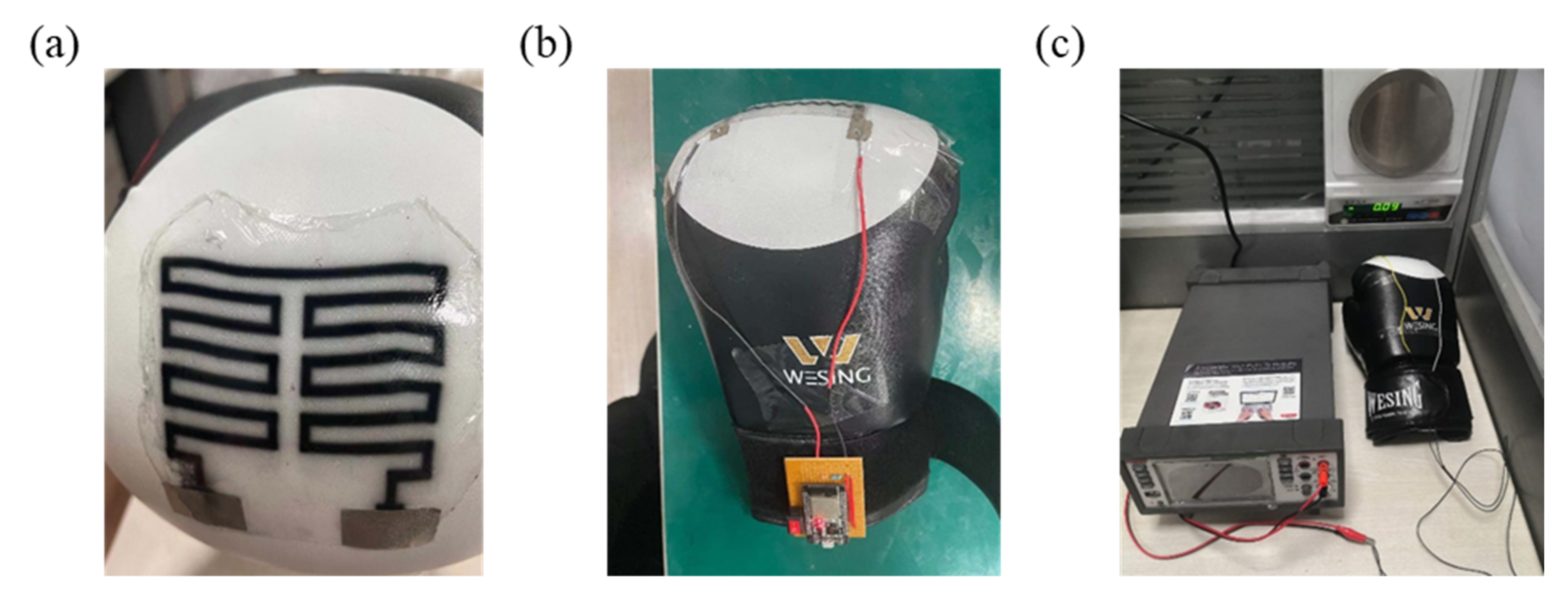
3.2.2. Smart Gloves
3.3. Testing
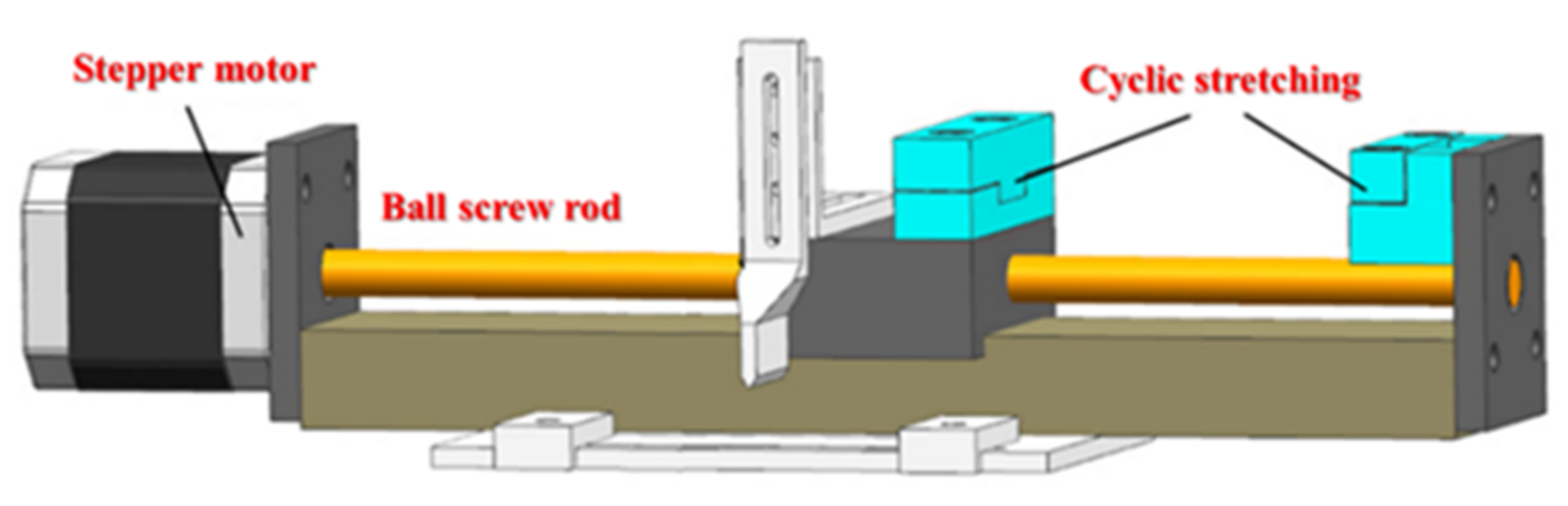
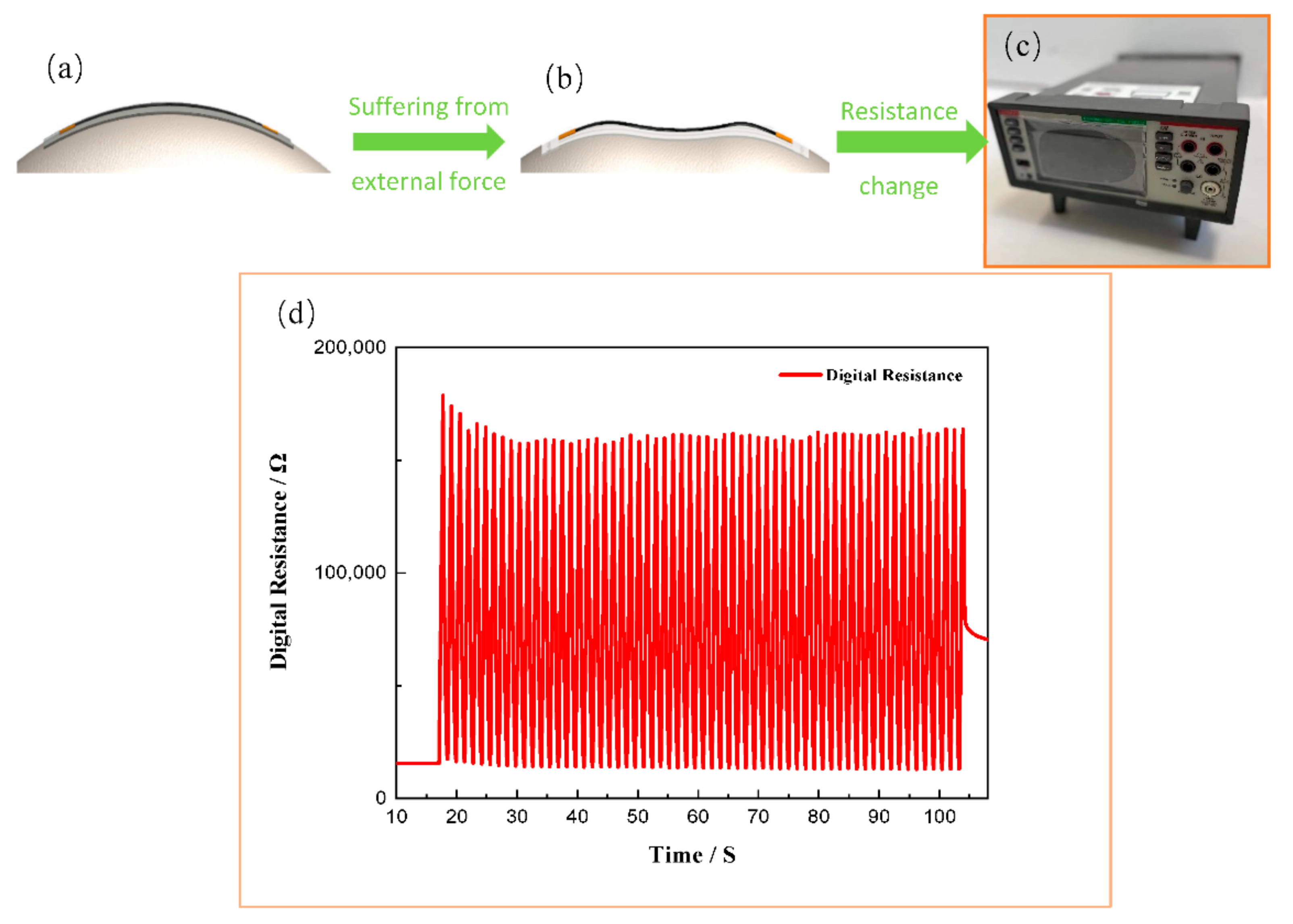
3.3.1. Tensile Test
3.3.2. Impact Force Test
4. Results and Discussion
4.1. Performance of the Flexible Strain Sensor
4.1.1. Sensitivity
Effect of the Plasma Treatment Process on Sensitivity
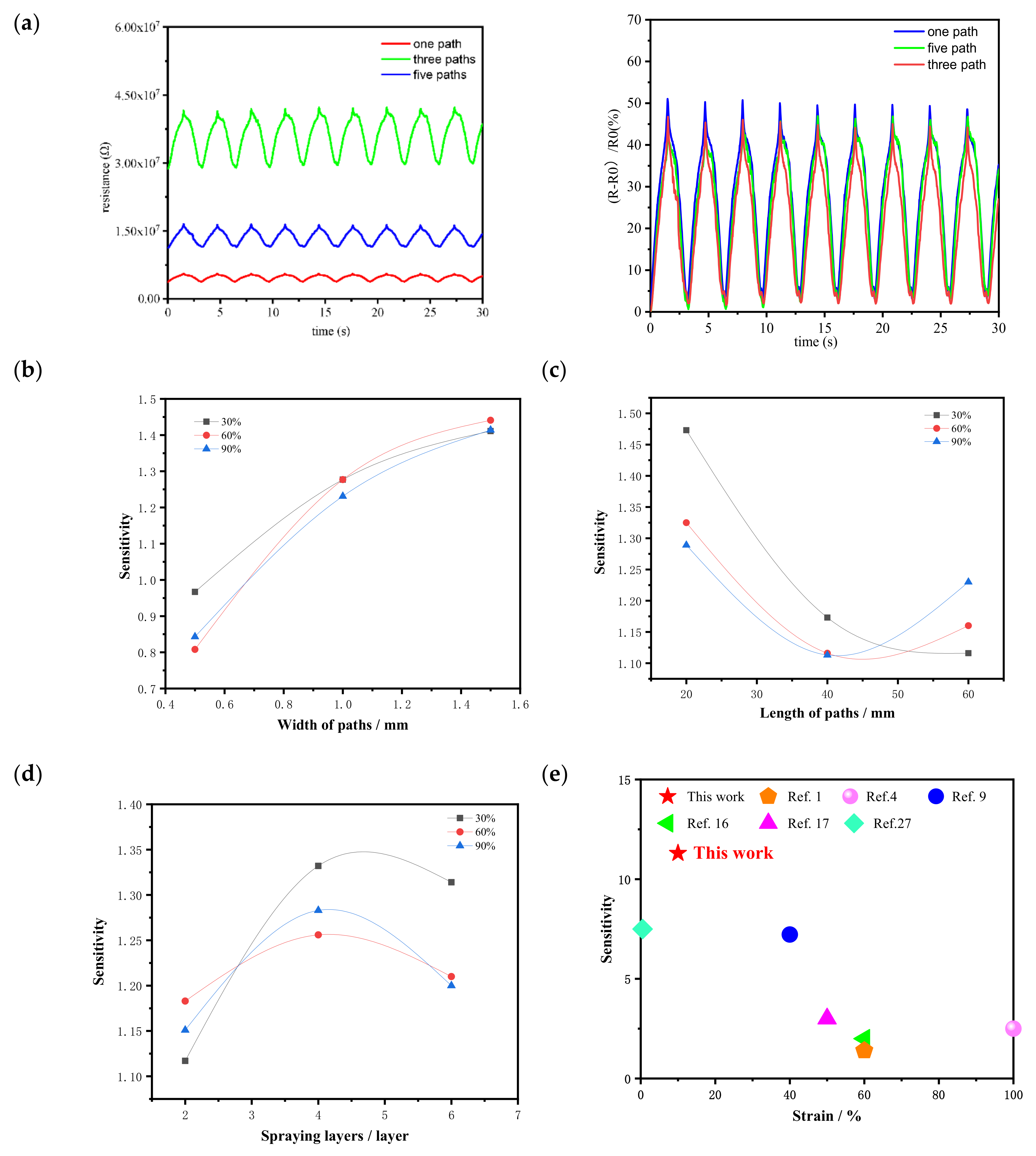
Effect of the Pattern Parameters on the Sensitivity

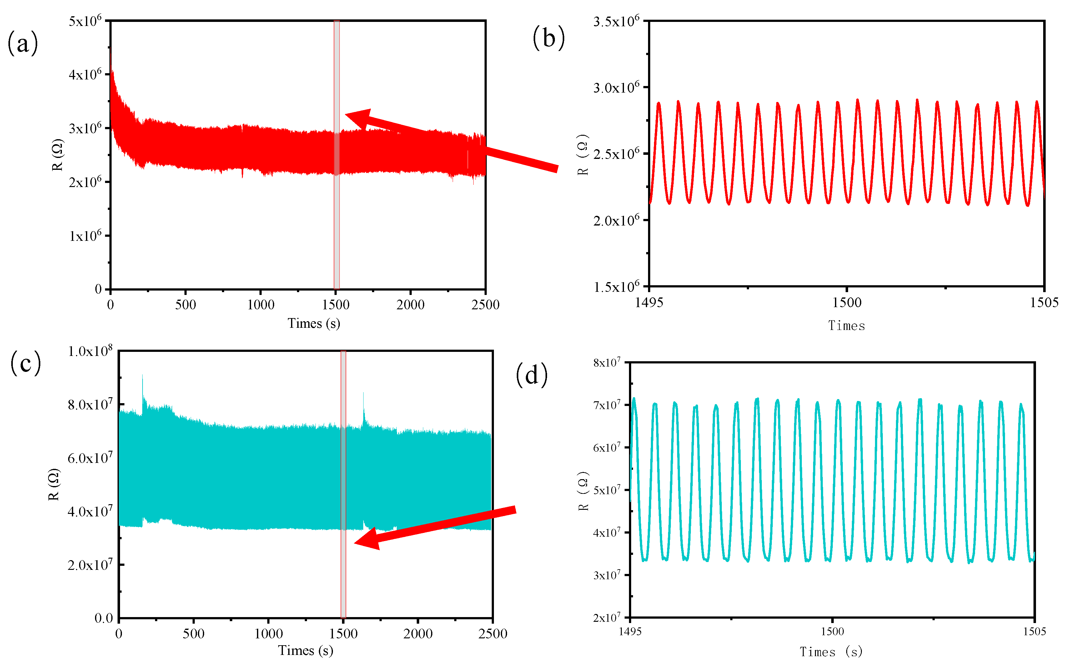
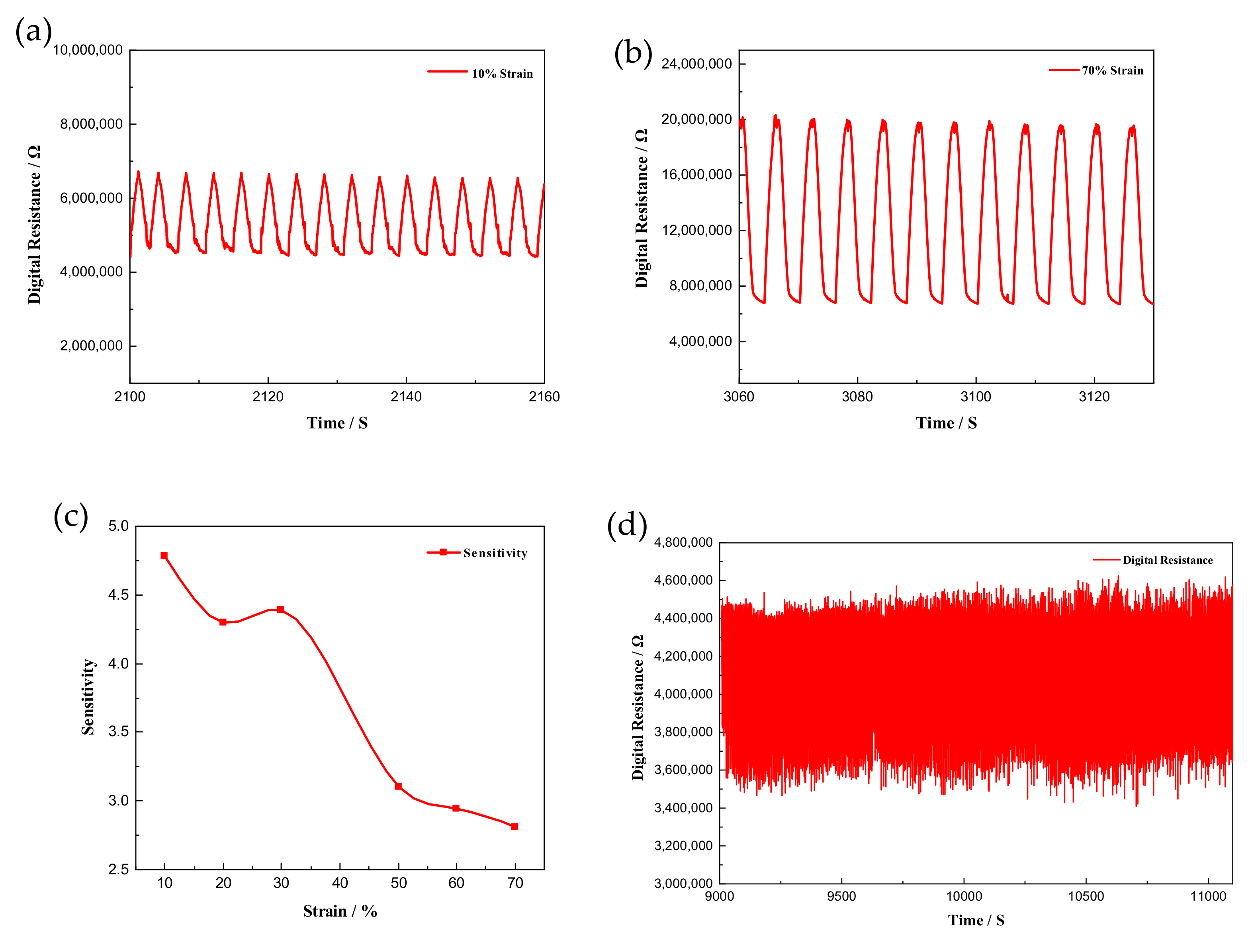
4.1.2. Cyclic Stability
4.1.3. Strain Range
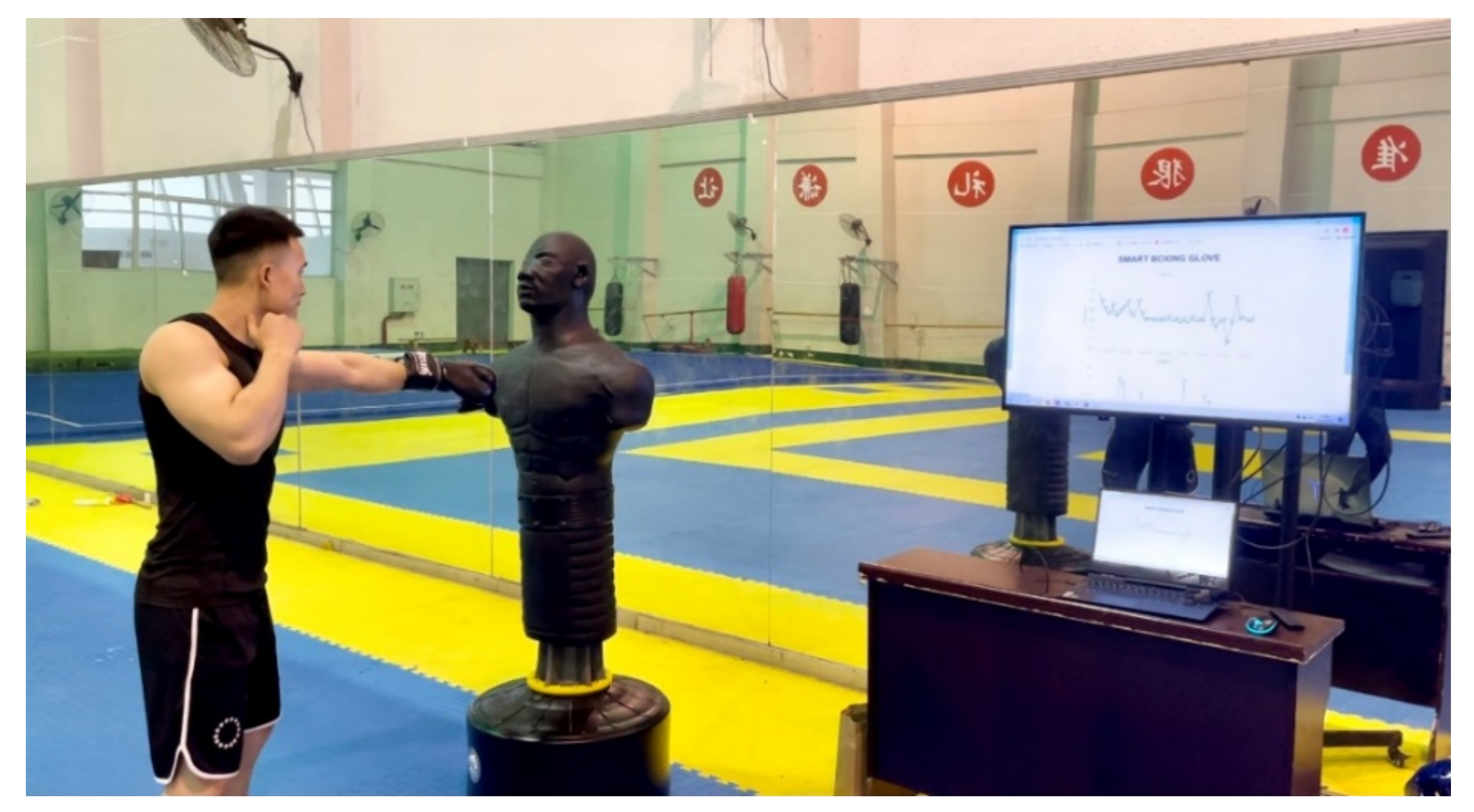
4.2. Performance Test of the Glove Prototype
4.2.1. Wi-Fi Data-Transmission Circuit
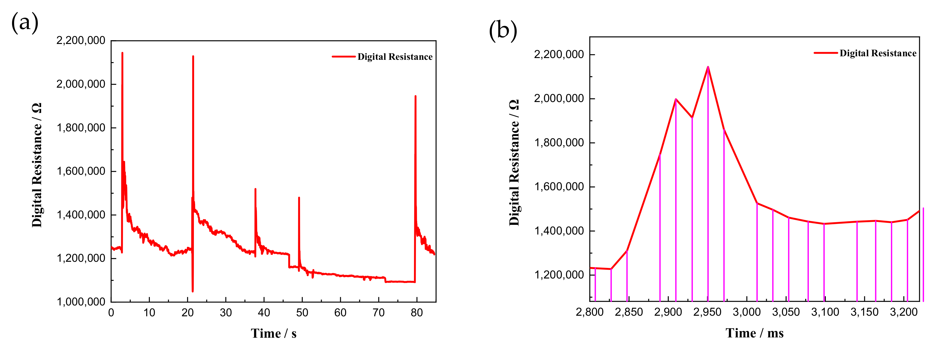
4.2.2. Response and Recovery Times
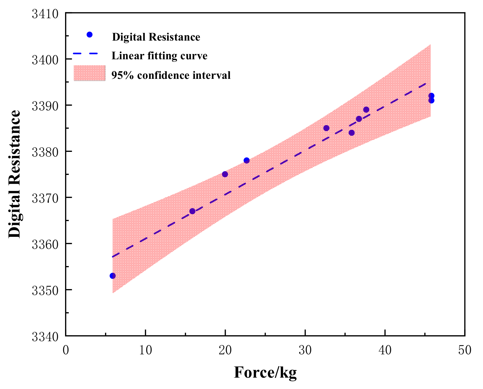
4.2.3. Force Curve

5. Conclusions
- (1)
- A novel plasma spraying method was proposed to fabricate flexible sensors, achieving high reproducibility of the sensor patterns;
- (2)
- The results were compared to those of an untreated sensor. The sensitivity of the flexible strain sensor could be increased from 3.9 to 11.5 when using the plasma treatment (an increase of 195%). However, the strain range was reduced to 10%, making the developed sensor only suitable for small-strain applications;
- (3)
- The effects of the pattern parameters on the sensitivity of the flexible sensor were explored. Multiple repeated paths could also increase the sensitivity of the sensor, but all paths had the same sensitivity;
- (4)
- A smart boxing glove that could transmit and monitor a striking force of 5–50 kg in real time was developed, showing a recovery time of 100 ms and a sensitivity of up to 1.05 kg;
- (5)
- The Wi-Fi data-transmission function of the ESP32 development board was used for real-time data collection and image display, which greatly improved the portability of the smart glove and would not affect the daily and competition use of the glove by boxing enthusiasts and athletes.
Author Contributions
Funding
Conflicts of Interest
Abbreviations
| EGaIn | Eutectic gallium–indium |
| TPU | Thermoplastic polyurethane |
| CNT | Carbon nanotube |
| MWCNT | Multiwalled carbon nanotube |
| MMAD | Mass median aerodynamic diameter |
| GF | Gauge factor |
| AP | Access point |
| IP | Internet Protocol |
References
- Mu, C.; Song, Y.; Huang, W.; Ran, A.; Sun, R.; Xie, W.; Zhang, H. Flexible Normal-Tangential Force Sensor with Opposite Resistance Responding for Highly Sensitive Artificial Skin. Adv. Funct. Mater. 2018, 28, 1707503. [Google Scholar] [CrossRef]
- Kumaresan, Y.; Ozioko, O.; Dahiya, R. Multifunctional electronic skin with a stack of temperature and pressure sensor arrays. IEEE Sens. J. 2021, 21, 26243–26251. [Google Scholar] [CrossRef]
- García Núñez, C.; Manjakkal, L.; Dahiya, R. Energy autonomous electronic skin. Npj Flex. Electron. 2019, 3, 1–24. [Google Scholar] [CrossRef]
- Dong, X.; Wei, Y.; Chen, S.; Lin, Y.; Liu, L.; Li, J. A linear and large-range pressure sensor based on a graphene/silver nanowires nanobiocomposites network and a hierarchical structural sponge. Compos. Sci. Technol. 2018, 155, 108–116. [Google Scholar] [CrossRef]
- Lee, C.J.; Park, K.H.; Han, C.J.; Oh, M.S.; You, B.; Kim, Y.-S.; Kim, J.-W. Crack-induced Ag nanowire networks for transparent, stretchable, and highly sensitive strain sensors. Sci. Rep. 2017, 7, 7959. [Google Scholar] [CrossRef]
- Huang, T.; He, P.; Wang, R.; Yang, S.; Sun, J.; Xie, X.; Ding, G. Porous fibers composed of polymer nanoball decorated graphene for wearable and highly sensitive strain sensors. Adv. Funct. Mater. 2019, 29, 1903732. [Google Scholar] [CrossRef]
- Jia, J.; Huang, G.; Deng, J.; Pan, K. Skin-inspired flexible and high-sensitivity pressure sensors based on rGO films with continuous-gradient wrinkles. Nanoscale 2019, 11, 4258–4266. [Google Scholar] [CrossRef]
- Lin, B.S.; Lee, I.J.; Chen, J.L. Novel assembled sensorized glove platform for comprehensive hand function assessment by using inertial sensors and force sensing resistors. IEEE Sens. J. 2019, 20, 3379–3389. [Google Scholar] [CrossRef]
- Li, T.; Li, J.; Zhong, A.; Han, F.; Sun, R.; Wong, C.P.; Niu, F.; Zhang, G.; Jin, Y. A flexible strain sensor based on CNTs/PDMS microspheres for human motion detection. Sens. Actuators A Phys. 2020, 306, 111959. [Google Scholar] [CrossRef]
- Jeong, Y.R.; Kim, J.; Xie, Z.; Xue, Y.; Won, S.M.; Lee, G.; Jin, S.W.; Hong, S.Y.; Feng, X.; Huang, Y.; et al. A skin-attachable, stretchable integrated system based on liquid GaInSn for wireless human motion monitoring with multi-site sensing capabilities. NPG Asia Mater. 2017, 9, e443. [Google Scholar] [CrossRef] [Green Version]
- Xu, K.; Lu, Y.; Takei, K. Flexible hybrid sensor systems with feedback functions. Adv. Funct. Mater. 2021, 31, 2007436. [Google Scholar] [CrossRef]
- Ozlu, B.; Shim, B.S. Flexible and wearable PEDOT-paper pressure sensor for detecting human voice. In Proceedings of the 2021 IEEE International Conference on Big Data and Smart Computing (BigComp), Jeju Island, Korea, 17–20 January 2021; pp. 317–320. [Google Scholar]
- Kim, S.; Lee, J.; Choi, B. Stretching and twisting sensing with liquid-metal strain gauges printed on silicone elastomers. IEEE Sens. J. 2015, 15, 6077–6078. [Google Scholar] [CrossRef]
- Shintake, J.; Piskarev, Y.; Jeong, S.H.; Floreano, D. Ultrastretchable strain sensors using carbon black-filled elastomer composites and comparison of capacitive versus resistive sensors. Adv. Mater. Technol. 2018, 3, 1700284. [Google Scholar] [CrossRef] [Green Version]
- Khalid, H.R.; Choudhry, I.; Jang, D.; Abbas, N.; Haider, M.S.; Lee, H.K. Facile Synthesis of Sprayed CNTs Layer-Embedded Stretchable Sensors with Controllable Sensitivity. Polymers 2021, 13, 311. [Google Scholar] [CrossRef] [PubMed]
- Jin, L.; Chortos, A.; Lian, F.; Pop, E.; Linder, C.; Bao, Z.; Cai, W. Microstructural origin of resistance-strain hysteresis in carbon nanotube thin film conductors. Proc. Natl. Acad. Sci. USA 2018, 115, 1986–1991. [Google Scholar] [CrossRef] [Green Version]
- Christ, J.F.; Aliheidari, N.; Potschke, P.; Ameli, A. Bidirectional and Stretchable Piezoresistive Sensors Enabled by Multimaterial 3D Printing of Carbon Nanotube/Thermoplastic Polyurethane Nanocomposites. Polymers 2018, 11, 11. [Google Scholar] [CrossRef] [Green Version]
- Kim, S.; Oh, J.; Jeong, D.; Park, W.; Bae, J. Consistent and Reproducible Direct Ink Writing of Eutectic Gallium-Indium for High-Quality Soft Sensors. Soft Robot. 2018, 5, 601–612. [Google Scholar] [CrossRef]
- Katz, L. Innovations in sport technology: Implications for the future. In Proceedings of the 11th Congress of the International Association for Sport Information (IASI) Congress, Lausanne, Switzerland, 25–27 April 2001; pp. 55–64. [Google Scholar]
- Zhao, J.; Zhao, Z.; Xu, X. A design of a virtual boxing training system based on Kinect somatosensory sensor. Comput. Eng. Sci. 2015, 37, 1736–1741. [Google Scholar]
- Hahn, A.G.; Helmer, R.J.N.; Kelly, T.; Partridge, K.; Krajewski, A.; Blanchonette, I.; Barker, J.; Bruch, H.; Brydon, M.; Hooke, N.; et al. Development of an automated scoring system for amateur boxing. Procedia Eng. 2010, 2, 3095–3101. [Google Scholar] [CrossRef] [Green Version]
- Ishibashi, N.; Prathap, S.K.V.; Pandian, S.R. Design and fabrication of a smart punching bag with micro energy generator. In Proceedings of the 2017 IEEE Region 10 Symposium (TENSYMP), Cochin, India, 14–16 July 2017; pp. 1–6. [Google Scholar]
- Stoffels, E.; Flikweert, A.J.; Stoffels, W.W.; Kroesen, G. Plasma needle: A non-destructive atmospheric plasma source for fine surface treatment of (bio) materials. Plasma Sources Sci. Technol. 2002, 11, 383. [Google Scholar] [CrossRef]
- Shin, D.H.; Hong, Y.C.; Uhm, H.S. Generation of needle injection plasma at atmospheric pressure. IEEE Trans. Plasma Sci. 2006, 34, 2464–2465. [Google Scholar] [CrossRef]
- Lu, X.; Xiong, Z.; Zhao, F.; Xian, Y.; Xiong, Q.; Gong, W.; Zou, C.; Jiang, Z.; Pan, Y. A simple atmospheric pressure room-temperature air plasma needle device for biomedical applications. Appl. Phys. Lett. 2009, 95, 181501. [Google Scholar] [CrossRef]
- Lu, X.; Laroussi, M.; Puech, V. On atmospheric-pressure non-equilibrium plasma jets and plasma bullets. Plasma Sources Sci. Technol. 2012, 21, 034005. [Google Scholar] [CrossRef]
- Glowinski, S.; Ptak, M. A Kinematic Model of a Humanoid Lower Limb Exoskeleton with Pneumatic Actuators. Acta Bioeng. Biomech. 2021, 24, 2022. [Google Scholar]


| Device | Product Series | Manufacturer |
|---|---|---|
| Homemade low-temperature-plasma spraying device | / | / |
| Homemade tensile strain gage | / | / |
| Low-temperature-plasma experimental power supply | CTP-2000K | Nanjing Suman, Shenzhen Zhongyitong Technology Co., Ltd. |
| Liquid aerosol generator | HRH-WAG6 | Beijing Huironghe Technology Co., Ltd. |
| Glass rotameter | LZB-6 | Xiangjin Flow Meter Factory |
| Desktop multimeter | Tektronix DMM6500 | Guangzhou Xinjingyou Electronic Technology Co., Ltd. |
| Electronic balance | WXL-A66002 | Shenzhen Unlimited Weighing Instrument Co., Ltd. |
| Boxing gloves | JRS-12345 | Nine Suns Mountain/Nine Days Mountain |
| Oscilloscope | DPO 2024B | Ion Technology Co., Ltd. |
Publisher’s Note: MDPI stays neutral with regard to jurisdictional claims in published maps and institutional affiliations. |
© 2022 by the authors. Licensee MDPI, Basel, Switzerland. This article is an open access article distributed under the terms and conditions of the Creative Commons Attribution (CC BY) license (https://creativecommons.org/licenses/by/4.0/).
Share and Cite
Liao, Y.; Cheng, Y.; Zhuang, Z.; Li, R.; Yu, Y.; Wang, R.; Jiao, Z. Plasma-Sprayed Flexible Strain Sensor and Its Applications in Boxing Glove. Appl. Sci. 2022, 12, 8382. https://doi.org/10.3390/app12168382
Liao Y, Cheng Y, Zhuang Z, Li R, Yu Y, Wang R, Jiao Z. Plasma-Sprayed Flexible Strain Sensor and Its Applications in Boxing Glove. Applied Sciences. 2022; 12(16):8382. https://doi.org/10.3390/app12168382
Chicago/Turabian StyleLiao, Yongsheng, Yue Cheng, Zhongyu Zhuang, Rongjun Li, Yuan Yu, Ruixue Wang, and Zhiwei Jiao. 2022. "Plasma-Sprayed Flexible Strain Sensor and Its Applications in Boxing Glove" Applied Sciences 12, no. 16: 8382. https://doi.org/10.3390/app12168382