1. Introduction
With the advancement of aviation technology, artificial intelligence and information technology have become the focus of aviation research. Yang Wei, academician of Chinese Academy of Sciences, and Sun Cong, academician of Chinese Academy of Engineering, highlighted the importance of information and intelligence technologies in their discussions on the development of future fighter jets [
1,
2]. As an indispensable part of informatization, software architecture is the important foundation of avionics systems and artificial intelligence technology in avionics systems. The application of artificial intelligence technology and service-oriented architecture (SOA) in avionics systems has become the focus of avionics architecture. Expert systems that contain intelligent agents have been applied to improve the reliability and maintainability of avionics systems [
3]. A new generation of airborne human-computer interaction systems has been developed based on multi-agent systems to enhance situation awareness and decision-making through the pilot cockpit [
4]. Furthermore, recent studies have revealed that the SOA can help an avionics system not only improve its flexibility but also reduce the cost and human–computer interaction of updating features [
5,
6,
7]. Likewise, the SOA has been applied to avionics systems [
8,
9,
10,
11,
12].
However, with the increase in the scale of avionics systems, system design becomes increasingly complex; thus, modeling has become the focus of design work. Improvement of the modeling method of agents and SOA is the focus of current research. This paper proposed a novel modeling method of agents and SOA in avionics systems.
Agents in avionics systems can interact with the external environment autonomously. When the input changes, the working state of the agent will also change, and many attributes of the agent will also change under these states. In addition, SOA encapsulates functional units as services, and deploys and reuses them, which brings higher flexibility of software architecture and convenience of development. However, when SOA executes different applications, the difference of services invoked will lead to the change in system attributes. Such changes in the attributes of agents and SOA will bring difficulties in describing many of their characteristics, such as the task time delay, task reliability, processor scheduling policy, and so on. Traditional avionics system modeling methods lack accurate description of these changes and characteristics of agents and SOA; such inaccuracies in modeling will bring great difficulties to the analysis and design of the system, which may lead to software system failures and even serious accidents and dangers.
As an integrated system of software and hardware, the modeling method of avionics system needs to consider the modeling of integrated systems of software and hardware. Architecture analysis and design language (AADL), a representation method, is developed for designing and analyzing software and hardware architecture of an embedded real time system and its functional and non-functional properties [
13,
14,
15]. This modeling language mainly focuses on the binding relationship and interaction between system components, and adequately describes the complex real time embedded system architecture.
However, there are some issues to consider in the modeling work. First, the working state of the agent changes with the input and SOA is characterized by architectural flexibility and not only the encapsulation but also reuse of functions. These require a modeling method to effectively support the dynamic behavior of the system. Secondly, AADL language is suitable for modeling avionics systems, but the model of software architecture in existing avionics system modeling methods lacks dynamic behavior description. The mode component in AADL is suitable for describing dynamic behavior. Therefore, the combination of a traditional software architecture modeling method and a dynamic behavior description method, based on pattern components, provides a more accurate description of the dynamic behavior of the agent and SOA. At the same time, this model has very good compatibility with the existing avionics models based on AADL, so that the same model can describe the common software architecture and the agent and SOA at the same time, and accurately describe these complex features of the agent and SOA.
Based on the above content, this paper proposes a novel modeling method of agent and SOA based on AADL, aiming to improve the ability of model to describe agent and SOA by describing the dynamic behavior and attributes of agents and SOA in different states. Firstly, based on the change in the agent working state, the environmental input feedback and multi working states modeling method of the agent are proposed, aiming to describe the transition mechanism of the working state of the agent with external input and the attributes of the agent in different working states. In addition, considering the service-oriented encapsulation of SOA and the invocation of services by applications, an application and service modeling method of SOA is proposed, aiming to describe the encapsulation and reuse of services in SOA and the flexibility of software architecture, when executing different applications. Moreover, this modeling method is used to model an avionics system, including SOA and agents. Based on this model, the delay time of different agent working states and SOA execution of different applications are analyzed. The analysis results show that the system has different delay times under different inputs and different application execution, which accurately describes the attributes of agents in different states and SOA execution of different applications and proves the effectiveness of this method in practice.
In the remainder of this paper,
Section 2 briefly reviews the agents, SOA, and AADL, and
Section 3 presents the agents and SOA modeling method based on AADL. In
Section 4, a case study is introduced and the last section provides conclusions and future work.
3. Agents and SOA Modeling Method Based on AADL
This section introduces the characteristics of agents and SOA, and proposes a modeling method suitable for describing these characteristics based on AADL.
3.1. Modeling Method for Agents
Compared with traditional software, the agent can perceive the environment, solve problems by reasoning and respond to the external environment through actions. The working state of the agents will change autonomously according to the external input, leading to possible changes to the characteristics of the agents, such as software reliability, execution time and other attributes. Recent studies show that the component attributes have a significant influence on the quantitative analysis of the avionics system; as a result, the following section will stress the working state of the agents to describe and model the agents better.
An agent can be defined as
where
XA is the input set and
YA is the output set of the agent;
where
SA is the working state set of agent,
sAn denotes nth working state.
where
UA is the set of trigger conditions of the working state transition;
uAij denotes the trigger condition for transitioning from the ith working state to the jth working state.
In the process of modeling the agent, the appropriate components need to be selected to describe the agent first. The agent in the avionics system is the software with specific functions, so the modeling method of software is used to describe the agent. Therefore, the agent is represented by a process component, which receives input or output through interfaces on the process component. The input elements in set
XA and output elements in set
YA can be events, data or messages. Next, due to the multiple working states of an agent, the process component cannot describe its properties in different states, so modes are used to represent the working states in set
SA at the component level. In different modes, the properties of the process component can describe the detailed characteristics of the agent through different attribute values. In the trigger condition of mode transition, specified events, data or messages, which are in set
UA, can be set according to the characteristics of the agent to trigger the transition of the working mode of the agent. In
Figure 4, the following three states of agent p1 are set through the mode component: mode1, mode 2 and mode 3, and three conditions, trigger1, trigger2 and trigger3, are set to trigger the transition of the agent state.
3.2. Modeling Method for SOA
In the service-oriented architecture of avionics systems, various functional units are encapsulated as services through specific interfaces and protocols, and services have specific functions, which can be provided to other services or applications for use. SOA enables distributed deployment, composition, and reuse of services, eliminating differences in hardware platforms, operating systems, and programming languages. This loosely coupled and architecturally flexible architecture is difficult to describe with traditional static architecture modeling methods. If this process is described using a static architecture modeling approach, all services and applications need to be modeled and coexist with the overall system architecture, and repeated services need to be modeled repeatedly. This static architectural model cannot accurately describe the actual process by which SOA executes application.
An SOA can be defined as
where
XB is the input set and
YB is the output set of the SOA;
where
BB is the application set of SOA;
BBn denotes nth application.
where
SB is the service set of SOA;
SBn denotes nth service.
where
KB is the set of invocation relationships between applications and services;
kBn denotes the invocation relationship between nth application and corresponding services.
where
UB is the set of application requests;
uBn denotes the request to nth application.
Representing component configurations and connections in the system, the modes in AADL can be triggered by set events, data, or messages to switch from source mode to target mode. These characteristics of modes can model SOA better than traditional static architecture models.
In the modeling process of SOA, the service in set SB is first represented by process components. Since application will invoke one or more services, it is represented by the system component. System components can contain multiple process sub-components, which are used to represent the relationship between application and service. Next, the modes are used at the system level, and different modes of system components are used to represent different applications in set BB. Because the modes of system components can represent the configuration and connection of components in the system, the components and configuration relationships contained in different modes of system components are also different. System-level modes can be used to represent invocation relationships in set KB between applications and services. Based on this, the application request in UB is represented with a trigger condition for the mode transition, such as an event, data, or message, and the SOA system invokes the services and completes the application according to the application request. The trigger condition can enable the transition of the system component from the source mode to the target mode, that is, from the original application to the target application.
For example, in an SOA system, there is application X with two services A and B, application Y with three services A, C and D, and application Z with three services B and D. After service X is executed, the system receives service request Y and executes it. After service Y is executed, the system receives service request Z and executes it. To model this process using the proposed method, the service architecture in these applications should be described first, that is, the process component configuration in the system component. Then, the mode component is used to describe the target services executed by the system after receiving the service request. That is, the service request triggers the mode transition. As shown in
Figure 5, three different modes are used to describe the invocation of services by applications in the system. For example, when application Y is executed after receiving application request Y, the system application will transition from X.impl to Y.impl and call the internal services of Y.impl.
Similar to the modeling method for agents, during SOA modeling, other software components such as the thread component, thread group component, data component and corresponding attribute values of each component, can also be added to the process component to describe services in SOA in detail.
In addition, for the agent modeling method in the previous section, if the agent is regarded as an independent agent service in SOA, when the agent service is included in the application, it can be added to the system component, representing the application as a process component. The component-level modes used in the agent model to describe the state of work can work together without conflict with the system-level modes used in the SOA model to describe the application.
4. Case Study
Based on a case study of some functions in an avionics system, modeling of advanced avionics architecture, including agents and SOA, is completed.
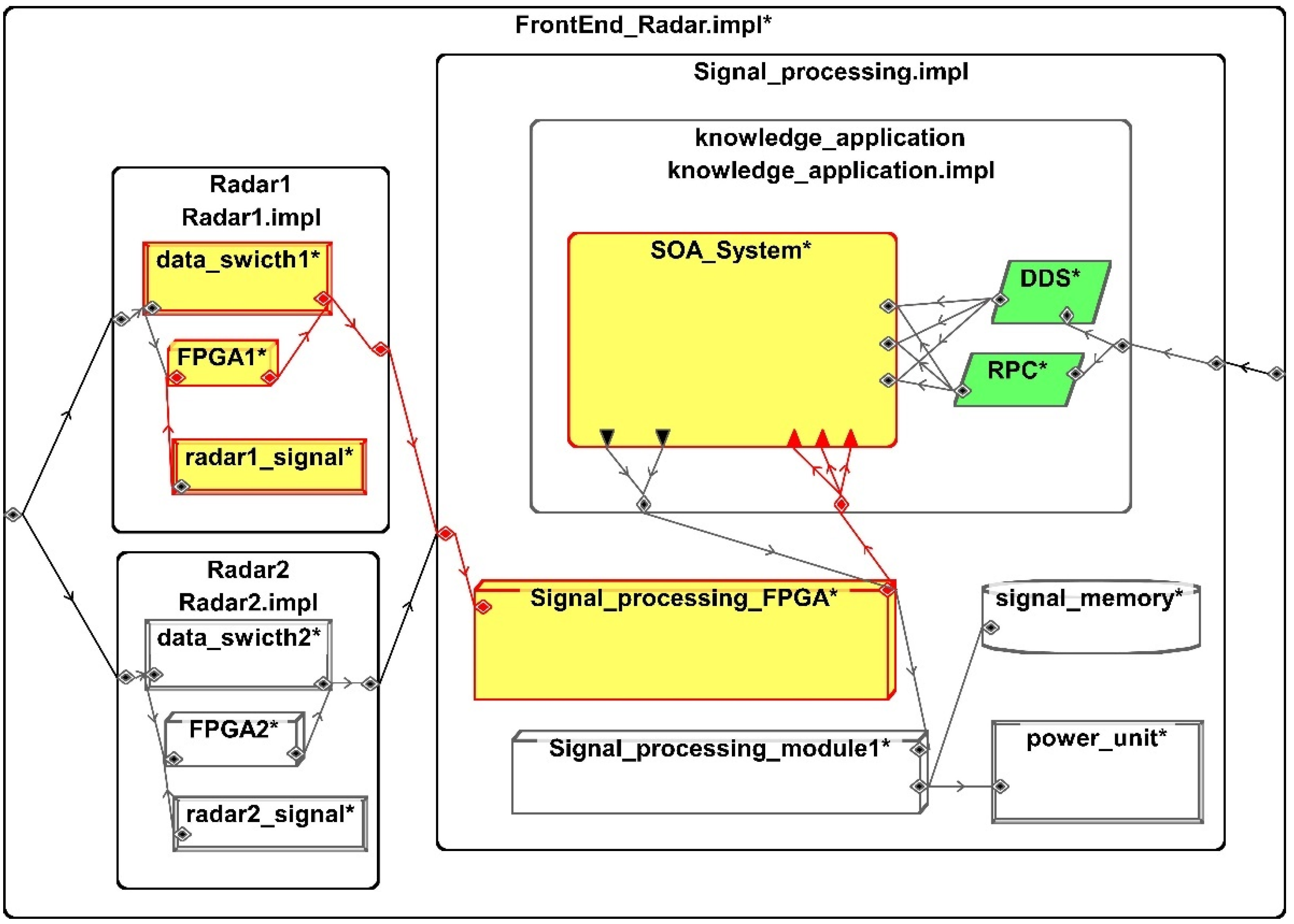
The model is divided into the following three levels: front-end radar module, signal processing module and application module. With the hierarchical distribution, the modeling method of “signal-data-knowledge” is adopted. In the working process, the front-end radar module detects the target signal, and the signal processing module processes the radar signal to obtain data. The application module analyzes and processes the data to obtain knowledge, which is used in the follow-up work, such as path planning, communication and equipment monitoring.
The front-end radar module contains two radar modules. The radar module contains the radar detection equipment, FPGA module and switch. The device component represents the radar detection equipment and switch, and the processor component represents the FPGA module. Signal processing module includes the signal processor, FPGA module, power supply and data storage module. The device component represents the power supply, processor component FPGA module and signal processor, and memory component data storage module. The application module contains multiple software components, such as the Data Distribution Service (DDS), Remote Procedure Call (RPC) component and SOA System. The SOA system includes intelligent path planning, communication and equipment health status monitoring and related services. The SOA system is represented by the system component and the DDS and RPC component are represented by the process component. The graphical model of the three-level architecture of the avionics system is shown in
Figure 6. Moreover, in
Figure 6, the green part represents the signal level, the red part represents the data level and the yellow part represents the knowledge level. These three parts together form the three-level architecture.
In the SOA system, there are three applications, including intelligent path planning, communication and equipment health monitoring, and five services, including the path planning service, communication management service, signal reception service, signal transmission service, equipment signal acquisition service and equipment status analysis service. The mapping between application and service is as follows: intelligent path planning application includes the intelligent path planning service, signal reception service, and signal transmission service. Communication application includes the communication management service, signal reception service and signal transmission service. Equipment health monitoring application includes the equipment signal collection service and equipment status analysis service.
The path planning service includes an agent, and the agent modeling method is used to model the service. According to the characteristics of the agents, its state is divided into the following three states: target recognition, obstacle warning and path planning. The agent service has different execution time attributes in the three states, and its state transition is triggered by different image data input.
This system is modeled using the SOA modeling method in this article. The system component is used to describe the intelligent path planning, communication and device health monitoring in the system, and the process component is used to describe the services contained in the application. The application transition of the system is triggered by task request events. For intelligent path planning services that contain agents, process components are used to describe them. A graphical model of the SOA system is shown in
Figure 7. In
Figure 7, the colors red, yellow and green are used to represent three different applications, including intelligent path planning, communication and equipment health monitoring. In the traditional software system modeling method, these three different applications need to be deployed independently in the system with fixed architecture simultaneously. However, the SOA executes the application and invokes the corresponding service upon request, so the modeling method presented in this paper better describes how SOA works and its flexibility.
In this case, services with the same name in different applications refer to repeated invocation of the same service. As can be observed from the AADL model code snippets below, the signal reception service and signal transmission service in the intelligent path planning application and communication application are invocations to the same service rather than repeated implementation of the same function. This modeling method reflects the loose coupling and architectural flexibility of SOA. Assuming that new applications added to the model in the future contain the same service, the existing service can be invoked in the same way.
Based on this model, this case will show how this modeling method works in practice by analyzing the delay time of a task path. In this path, radar1_signal in Radar1 first obtains the signal and sends it to FPGA1 for preliminary signal processing, Then, the processed data is transferred from data_switch1 to Signal_processing_FPGA for secondary data processing. The processed data is then transmitted to the SOA_System, which executes applications based on system tasks, such as path planning or equipment health monitoring. The path information is as follows: radar1_signal-FPGA1-data_Switch1-Signal_Processing_FPGA-SOA_System. The SOA_System receives control instructions from DDS and RPC to execute a specific application. For intelligent target analysis applications that include agents, the image data will trigger the agent working state transition. The task path and the components on the path model are highlighted in red, yellow, and green in
Figure 8.
The delay time of the hardware components in the task path are shown in
Table 1. There are four hardware components in the task path.
The delay time of the SOA_System and services inside are shown in
Table 2. There are seven services in the SOA_System.
For the target analysis service with agents, there are three working states, target recognition, obstacle warning, path planning. In the different working states, the delay time of the target analysis service is shown in
Table 3.
Based on the above information, the delay time of this task path in three different application execution cases is analyzed. In the first case, the avionics system sends an application request through RPC to enable the SOA system to execute the equipment health monitoring application, and Equation (9) shows the calculation process of system delay time
T1 in this case.
In the second case, the avionics system sends an application request through RPC to make the SOA system execute intelligent target analysis application. At this time, the image information from the radar triggers the agent to transition to the obstacle warning state, and Equation (10) shows the calculation process of system delay time
T2 in this case.
In the third case, the avionics system sends an application request through RPC to make the SOA system execute intelligent target analysis application. At this time, the image information from the radar triggers the agent to transition to the path planning state, and Equation (11) shows the calculation process of system delay time
T3 in this case.
Through the comparison of the system delay time in
Table 4, the same task path in the system has different results, and the SOA executes different applications and the external input triggers different agent working states. It can be observed that the modeling method proposed in this paper can more accurately describe the working state of the agent, the SOA working process and the system attributes in the execution of different applications, and in practice, can improve the accuracy and effectiveness of the analysis.
5. Conclusions and Future Work
By aiming to solve the problems of the existing modeling methods in describing the dynamic behavior and attribute changes in the agent and SOA in avionics systems, this study proposes a novel modeling method of agents and SOA in an avionics system based on AADL and modes. Firstly, according to the change in the working state of the agent, the environmental input feedback and multi working states modeling method of the agent are proposed based on the AADL, and the transition mechanism of the agent working state with the external input is described. On this basis, the attributes of the agent under different working states are described. Secondly, considering the service-oriented encapsulation and reuse of functions by SOA and the invocation of services by applications, an application and service modeling method is proposed based on AADL, aiming to describe the application, service and software systems in SOA, and describe the system’s attribute parameters based on this. Compared with the current methods and technologies, the method proposed in this paper mainly reflects the advantages of two aspects. On the one hand, by modeling the agent dynamic behavior, the relationship between the agent working state change and the input is described. On the other hand, through the modeling of SOA services and applications, the architecture characteristics and attributes of SOA are described more accurately. In addition, this method has good compatibility with the existing AADL model of avionics systems, and has obvious effects in practice, which is of great significance to the design and analysis of avionics systems.
In the subsequent research, the modeling method will be refined and improved, and based on this, the system model analysis method, including agents and SOA, will be systematically studied.


