Article

Systematic Methods to Increase the Lifetime of Mechanical Products Such as Refrigerators by Employing Parametric Accelerated Life Testing

by
Seongwoo Woo
1,*,
Dennis L. O’Neal
2 and
Yimer Mohammed Hassen
1
1
Manufacturing Technology, Mechanical Technology Faculty, Ethiopian Technical University, Addis Ababa P.O. Box 190310, Ethiopia
2
Department of Mechanical Engineering, School of Engineering and Computer Science, Baylor University, Waco, TX 76798-7356, USA
*
Author to whom correspondence should be addressed.
Appl. Sci. 2022, 12(15), 7484; https://doi.org/10.3390/app12157484
Submission received: 25 June 2022 / Revised: 12 July 2022 / Accepted: 24 July 2022 / Published: 26 July 2022
(This article belongs to the Special Issue Advances on Structural Engineering, Volume III)

Abstract

:
This investigation practically explains the implementation of parametric accelerated life testing (ALT) as an algorithm to recognize design imperfection and rectify it in creating a reliable quantitative (RQ) statement by sample size equation. It covers: (1) a module BX life that X% of a collection of system items is unsuccessful with an ALT plan, (2) design for fatigue, (3) ALTs with alterations, and (4) discernment as to if the final design(s) obtains the targeted BX lifetime. A (generalized) life–stress formulation by the linear transport process is recommended for the mathematical work of the parametric model. As a case study, an ice-maker including gear system in a refrigerator was utilized. The gear teeth made of cast iron (carbon, 3 wt% and silicon, 2 wt%) was fracturing in a refrigerator ice-maker. To reproduce the field failure and rectify the problematic designs in the marketplace, a parametric ALT was carried out. At the first ALT, the gear teeth made of cast iron partly cracked and fractured under severe cold conditions (below −20 °C) in the freezer. It was modified by changing the material from cast iron to a sinter-hardened powder metallurgy nickel steel because high fatigue strength in the low temperature was required. At the second ALT, we discovered the fractured helix made of polycarbonates (PC). As a modification, strengthened rib on the front and side of the helix the thickness of gear teeth was attached. At the third ALT, there was no concern, and the life of the auger motor including gear system was manifested to have a B1 life 10 years.

1. Introduction

Because of aggressive needs in the marketplace, mechanical products might be designed to be desired functioning and high reliability. After the system designs are assessed before launching, new attributes are swiftly integrated into a product and brought to the market. The application of all these newly developed features affects a wide range of customer sectors where structural safety is a major concern: automobile, refrigerator, airplane, nuclear power plants, civil or naval structures, etc. With either restricted trial or no evident apprehension of how introduced design traits can be employed by the end-user, system introductions with design flaws can badly affect the manufacturer’s brand [1].
To transmit torque and speed, a gear system of an auger motor utilized in a refrigerator ice-maker is a rotating circular mechanical part having cut teeth, which mesh with another (compatible) toothed component. The advantages of gear drive are an exact velocity ratio, large powers, lofty efficiency, reliable service, and compact layout. On the other hand, the manufacture of gears requires particular tools and apparatuses. If there is a mistake in the cutting teeth, it causes vibration and noise in functioning. The basic operation of gears is analogous to that of levers. That is, the auger motor assembly including the gear system is designed to crush the ice through a greater rotational torque by decelerating speed through a plurality of driven gears interlocked with a drive pinion gear installed in the input shaft. To stop a gear system from being unsuccessful in the field before its expected lifetime, a company should prove the new gear combined with appropriate ISO Standards [2,3] and an information sheet [4] and/or properly carry out reliability testing before the product is launched.
The Boeing 737 MAX passenger aircraft from March 2019 to December 2020 was grounded after 346 persons lost their life in pair crashes. The airplanes adopted the CFM International LEAP-1B engines using the optimized 68-inch fan design; these engines consumed 12% less fuel and were 7% lighter than other engines [5]. Investigators including the Ethiopian Civil Aviation Authority had tentatively deduced that the crash was created by the aircraft’s design-engine. To secure a product is not unsuccessful in the market, problematic parts need to be recognized and altered by utilizing a systematic testing method-parametric ALT, which may generate reliability quantitative (RQ) statements [6].
Product material flaws, such as cracks, notches, local thin areas, etc., when subjected to repetitive (impact) loads, can cause fatigue to occur. Fatigue is the main origin of the lack of success in metallized components, describing approximately 80–95% of whole structural failures or economic losses [7]. That is, fatigue in metals becomes visible in the form of cracks, which develop in regions that stress may collect, such as grooves, sharp-edged, holes, etc., and propagate it. Structural failures in any of these sectors may have evident serious consequences in terms of human lives and environmental disasters. It is necessary to understand the different mechanisms generating critical and subcritical processes in the structural materials and to develop assessment techniques and management procedures for the corresponding structures.
In order to avoid these structural failures, the ALT integrated with the reliability block diagram has been carried out as an alternative method for solving product problems [8]. It covered a test scheme for the product, recognizing failure mechanics’ fracture and fatigue and utilizing sample size formulation, elevated loads, etc. Elsayed [9] grouped statistical, statistics/physics, and experimental/physics—accepted mock-ups for failure model. Meeker [10] proposed numerous empirical procedures to make arrangements for an ALT. Performing a parametric ALT [11,12] involves several notions such as the BX life for the systematic test, a simple life-stress model, sample size equation, and fracture mechanics because failure can instantly appear due to vulnerable parts in a module system [13,14,15]. The present test approach [16,17,18,19] cannot be easy to reproduce the design defects of parts in a multi-module product because the techniques evaluate too few samples and insufficient testing time.
To robustly acquire the design of a mechanical product, designers have used established approaches such as the strength of materials [20]. Attention is being paid to the development of engineering procedures defining the structural integrity conditions of a given component. Engineers also have utilized quantum mechanics to recognize which fatigue failures started from the atomic and microstructural scales in numerous metallic alloys or a lot of engineering plastics [21,22]. To recognize the fatigue origin of a mechanical system, a (generalized) life-stress formulation may be utilized as an established design way and the associated approaches to recognize the lack of success of electronic components due to material flaws or tiny cracks. Finite element methods (FEMs) and the strength of material cannot recognize the origin of failure because field failure stochastically occurs in the areas of locally high stress concentrations, not continuum in the material [23,24,25,26]. Alternatively, there are other ways—such as structural health monitoring (SHM)—which permit for the observation of the failure origin [27]. However, it is not easy to attain test data for multi-module systems because comprehensive testing might have been necessitated, which may be too expensive due to the period of time and required samples.
To manifest the success of recognizing and modifying the design flaws of a mechanical system, a parametric ALT may be utilized as a systematic method that produces the mission cycles such as RQ specifications. It encloses: (1) a product BX lifetime produced on the ALT procedure, (2) a load test, (3) adapted ALTs with modifications, and (4) an evaluation of whether the system design(s) attains the targeted BX life. The (generalized) time-to-failure formulation, the sample size formulation, and BX lifetime are proposed. To confirm the validity of ALT, it would be required to observe the initiation of the new design in the field to secure that it passed the objective reliability. A gear system of an ice-maker in a domestic refrigerator subjected to repetitive impact loading under severe cold conditions is utilized to exemplify this systematic method.

2. Parametric ALT for Mechanical Product

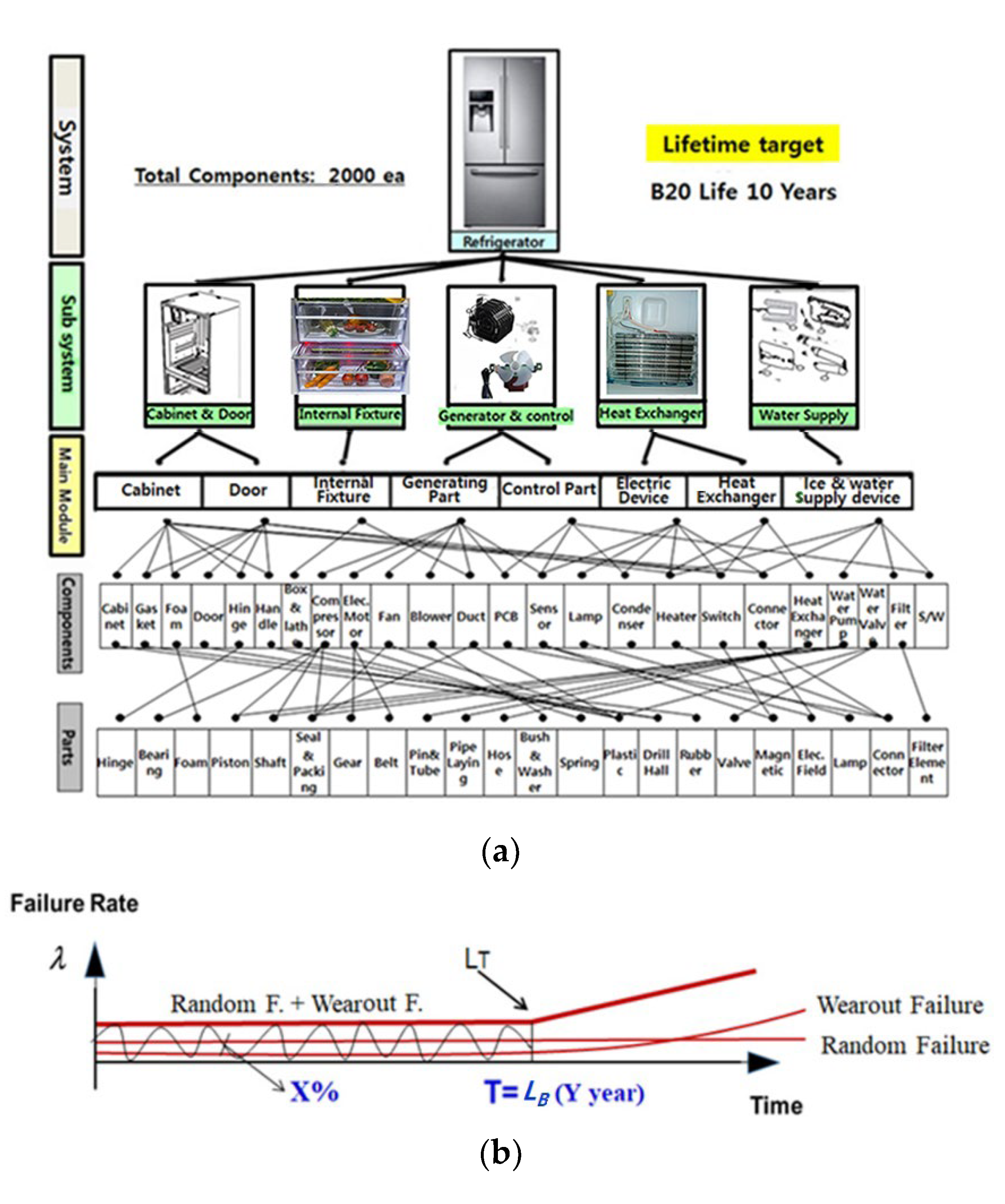
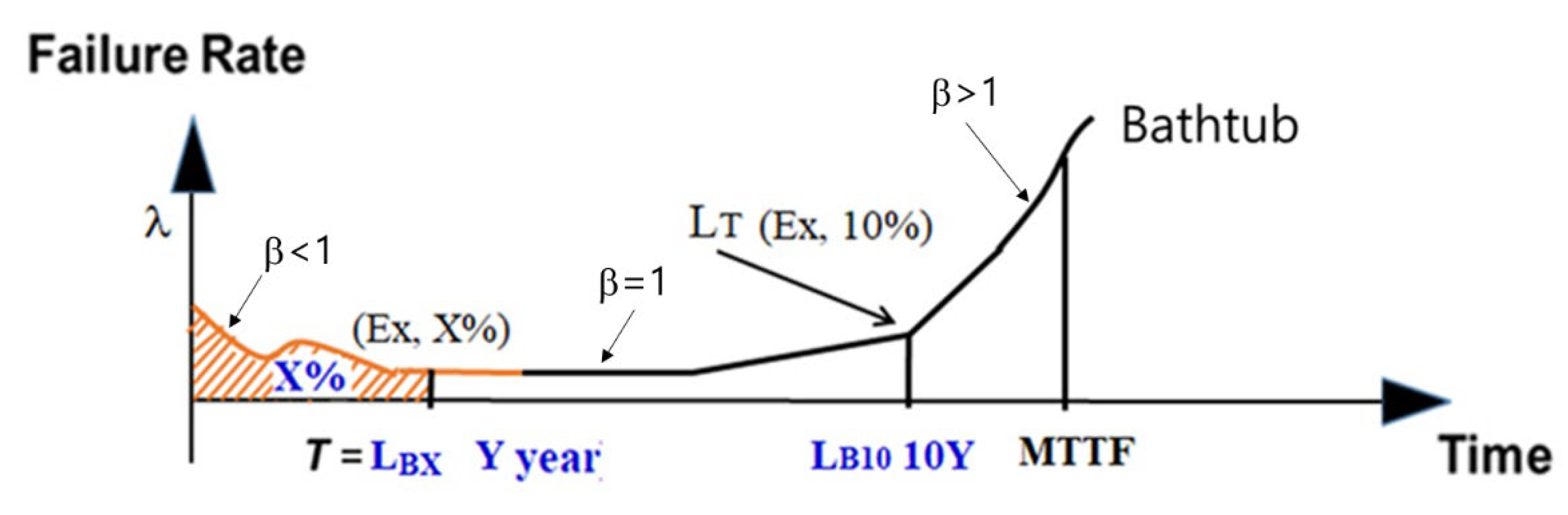
2.1. BX Lifetime in a Product

In products, power may be utilized to a mechanical advantage to supply a task that necessitates forces and motion by properly adapting mechanisms. In the process, they will be subjected to repetitive loading. They should have a robust design for the anticipated stresses. An instance is a domestic refrigerator, which is planned to give chilled air from an evaporator and preserve the freshness of foods. One of the refrigerator modules is the ice-maker, including a gear system, which is to decrease the speed and grow the torque. As a result, an ice-maker can obtain sufficient torque to crush the ice. A refrigerator can also include a range of subsystems (or modules)—the door, cabinet, shelves and drawers, controlled instruments, motor and electronics, compressor, evaporator and condenser, water supplying equipment, and numerous unlike components. The lifetime of the refrigerator is determined by the wear-out (or random) failure of a newly designed module such as the ice-maker, including the auger motor with a gear system that has design defects (Figure 1).
To carry out a parametric ALT, the BX lifetime (or “Bearing Life”), LB, might be determined as an index of the system life. The BX lifetime metric originated from the bearing manufacturing but has become an index for product lifetime that can be employed in various industries today. That is, BX life is a passed time when X% of a group of products under consideration is unsuccessful. A “BX life Y years” is a manner for showing the product life. If a product is a B20 life 10 years, it signifies that 20% of a collection of samples under consideration will fail during 10 years of working. By using this measure, the ALT may recognize the cumulative failure rate and satisfy the field demands for the life needs of the system.
For instance, a refrigerator has about 2000 parts, including ice-makers. If an ice-maker has design defects, it may affect the possible life of the refrigerator. If a refrigerator’s life is targeted to be a B20 life 10 years, the life of each unit might be a B1 life 10 years because the refrigerator is made up of 20 units and each unit has 100 parts.

2.2. Positioning a Total Parametric ALT Procedure

The reliability of a mechanical product may be defined as the ability required to continually carrying out the planned function under described operational/environmental circumstances for a needed period of time [28]. If system reliability is explained by utilizing a “bathtub curve”, it is consisted of three sections: (1) in the Section 1, during the premature system lifetime, there is some lessening in the failure rate; (2) in the Section 2, during its center life, there is a comparatively continual failure rate; and (3) in the Section 3, there is an increasing failure rate until the last lifetime of the system is reached. These categories can be explained according to shape parameter of the Weibull distribution.
If T is a random variable designating the time to failure in Figure 2, the proportion of outliving at time t may be stated as:
R t = P T > t
The accumulative distribution function (CDF), F t , is F t o r   X = 1 R t . The failure rate, λ, on the slanted bathtub curve in Figure 2 can be expressed as:
λ t = f t R t = d F t / d t R t = R t R t
where f is the failure density function.
If the failure rate in Equation (2) finds the integral, the X% accumulative failure, F(LB), at T = LB may be attained as follows:
F = X = 0 T λ t d t = l n R L B λ L B
Assuming that T1 shall be the time of the earliest failure in the Section 2 of the bathtub, the reliability function R(t) can also be obtained as:
R t = P T 1 > t = P no failure ° in 0 , t = m 0 e m 0 ! = e m = e λ t
As the product life is enhanced, the failure rate in the market will drop down. Instead, the system life extends. For such circumstances, the reliability of a mechanical product might be declared as follows:
R L B = 1 F L B = e λ L B 1   λ L B
The equation can be proved below roughly 20% of the cumulative failure [29]. We also know that the product reliability (or unreliability) can be obtained from the multiplication of failure rate and lifetime in Equations (3) and (5).
As a case study in this study, an ice-maker including an auger motor with a gear system repeatedly requires a straightforward mechanical operation: (1) water provides the ice-tray; (2) water will freeze into ice by blowing chilled air through the evaporator (heat exchanger); and (3) the ice harvests until the ice bucket is in full. As the consumer exert force on the lever to move it away, crushed (or cubed) ice will dispense. The unsuccessful products returned from the marketplace were crucial for comprehending and distinguishing the repeated usage ways of consumers and recognizing design defects equipped in the structural system. Based on the market statistics, the root cause(s) of the problematical ice-maker including a gear system was identified. After putting the targeted lifetime by using a parametric ALT, LB, the mechanical system might be altered by recognizing the problematic parts and modifying them (Figure 3).
To put the targeted life of a mechanical product—an ice-maker—by parametric ALT, which is made of up to eight modules (or subsystems) (See Figure 1a), there are the next potential modules: (1) altered individualistic units, (2) new individualistic units, and (3) alike individualistic units to the previous design based on a requirement in the market. The altered ice-maker in the refrigerator examined here is utilized as a case investigation. It was initially altered to increase the performance of the ice-maker including an auger motor with a gear system and make the product higher quality in the market. However, the modified ice-maker had design defects that are in need of being altered because of field failures.
The modified module E from the market data had a failure rate of 0.31% per year and a B1 life of 3.2 years (Table 1). Based on field details, the lifetime of the ice-maker, including the auger motor with a gear system, was an anticipated B1 life of 1.61 years because there was a failure rate of 0.3% per year. To fulfil customer requirements, a new life of a product such as an ice-maker including an auger motor with a gear system was aimed to be a B1 life 10 years.

2.3. (Generalized) Failure Model and Sample Size Formulation

Mechanical systems generally move power from one place to another by choosing a suitable mechanism, such as the gear system in an ice-maker auger motor. As the consumer wants ice, an ice-maker in a refrigerator as a newly designed function is added. The main parts in an ice-maker are made up of the auger motor, helix support, bucket case, blade dispenser, helix dispenser clamp, helix upper dispenser, blade, etc.
An auger motor as a gear train is two or more gears functioning jointly by engaging their teeth and rotating each other in a system to cause torque and speed. That is, as electric motors are utilized and the gear systems decrease speed and increase torque. That is, the auger motor driven by an alternating current (AC) increases the torque through the gear box to deliver the ice and crush it at the end of an ice-maker. In the process, the system will be subjected to repetitive stresses because of (impact) loading due to crushing ice and the severely cold temperature. If there is a design flaw in the multi-module structure, which brings a strength when the (impact) loads are employed, the product may unexpectedly be unsuccessful in its anticipated life. So, the components with the field failure should be required to be fixed or replaced (Figure 4).
The principal issue for parametric ALT is to decide how fast the possible failure manner may be recognized by utilizing the mathematical work for the parametric model. To accomplish this purpose, it involves methodically preparing a simple failure illustration and deciding the accurate coefficients for the life model. That is, a life-stress (LS) model (or time-to-failure) that has stresses and reaction parameters should be developed. It therefore incorporates numerous failures through fatigue (or fracture). Fatigue failures on the exterior of a component can not only happen due to part stresses but also due to the flaws such as cracks or a thin surface.
That is, fatigue may initiate from matter defects—electron/void—which are arisen on a macro, microscopic, or nano range. From such a conceptual standpoint, it may be stated as transport processes such as the diffusion of shallow level dopants of silicon in semiconductors.
First of all, consider an electric particle that is constrained to move only in the x direction from x = 0 to x = a. The time-independent Schrodinger wave equation in operator form can be expressed as follows:
H ^ ψ = E ψ
where H ^ is the Hamiltonian operator in the x direction, ψ is the wave function, and E is (electron) energy.
If H ^ = h 2 8 π 2 m d 2 d x 2 + V , we can put this in Equation (6).
h 2 8 π 2 m d 2 ψ d x 2 + V ψ = E ψ   or   d 2 ψ d x 2 + 8 π 2 m h 2 E V ψ = 0
where m is electron mass, h is the Planck constant, and V is potential energy.
Because V = ∞ for outside the walls, this is possible only when ψ = 0 . That is, particles are not outside the walls. Because V = 0 inside the walls, Equation (7) can be stated as follows:
d 2 ψ d x 2 + 8 π 2 m h 2 E 0 ψ = 0   or   d 2 ψ d x 2 + K 2 ψ = 0
where K 2 = 8 π 2 m E h 2 .
We can assume the solution of Equation (8) as follows:
ψ x = A s i n K x + B c o s K x
where A, B = constants.
Because x = 0 or x = a at walls, ψ(0) = ψ a = 0 , B = 0, K = n π a , and E = n 2 h 2 8 m a 2 , n = 1,2,3,4
So, we can state Equation (9) as follows:
ψ x = A s i n n π a x
The probability of finding the particle in a small space between x and x + dx is given as follows:
0 a ψ 2 x d x = 1   or   0 a A s i n n π a x 2 d x = 1
So, we can obtain the solution of Equation (7) as follows:
ψ x = 2 a s i n n π a x
where ψ x + a = ψ x , a is (periodic) distance, and n is the principal quantum number.
The atoms of the crystal establish a series of potential barriers that hinder the movement of the charged impurities. As an electromagnetic field, ξ, is applied, the barriers of potential junction energy as a function of distance will be reduced and distorted/phase-shifted. The impurities in materials, produced through electronic motion, are easily migrated to the right because the passage to the left becomes difficult (Figure 5).
Transport processes therefore are stated as follows:
J = L X
where J is a flux vector that is identified as the transport attribute. X is stated as a driving force that is identified as slopes of electrical potential, fluid velocity, concentration, temperature, etc. L is a transport numerical quantity.
For example, the solid-state diffusion in semiconductor technology is of the most practical procedures that control the type and concentration of impurities in specific regions of a crystal. It includes electro-migration-induced voiding, the growth of chloride ions, and catching of electrons or holes.
The solid-state diffusion of impurities dopped in silicon J is amount/area per time. It could be formulated as [30,31]:
J = a C x a e x p q k T W 1 2 a ξ v
= a 2 v e q w / k T c o s h q a ξ 2 k T C x + 2 a v e q w / k T C s i n h q a ξ 2 k T = Φ x , t , T s i n h a ξ e x p Q k T = B s i n h a ξ e x p Q k T
where C is the concentration, q is the extent of electric charge, ν is the frequency rate of attempted jump, a is the distance between atoms, ξ is the exerted electric field, k is the Boltzmann’s constant, T is the absolute temperature, Q is the energy, and B is a constant.
The reaction process, which is dependent to speed, could additionally be formulated as:
K = K + K = a k T h e Δ E a S k T a k T h e Δ E + a S k T = B s i n h a S e x p Δ E k T
where K is the reaction rate, S is the (chemical) field effect, T is the temperature, k is Boltzmann’s parameter, E is the (activation) energy, and Δ is the difference.
The junction function, J, from Equations (14) and (15) could be stated as:
J = B s i n h ( a S ) e x p E a k T
If Equation (16) puts a reverse function, the life-stress (LS) prototype could be restated as:
T F = A s i n h ( a S ) 1 e x p E a k T
The sine hyperbolic form s i n h a S 1 in Equation (17) has characteristics as follows: (Figure 6):
  • S 1 
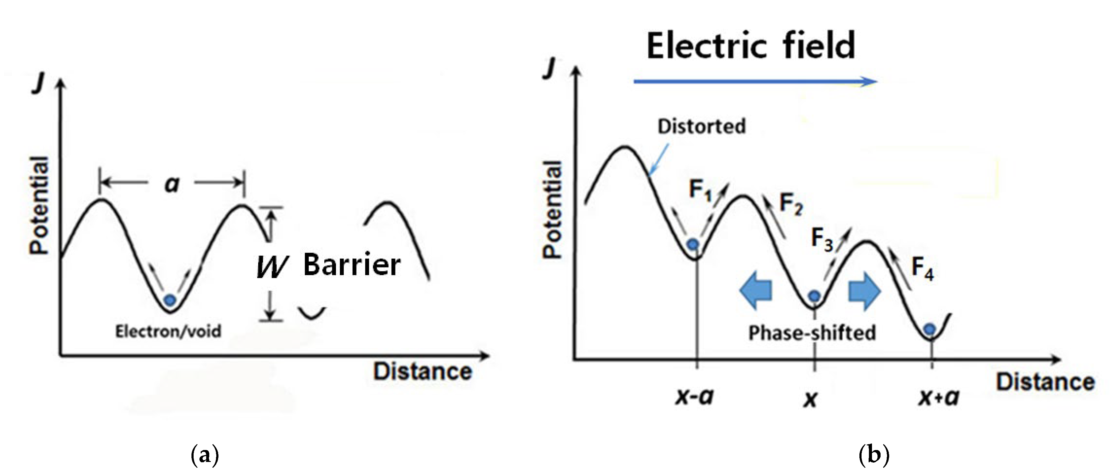
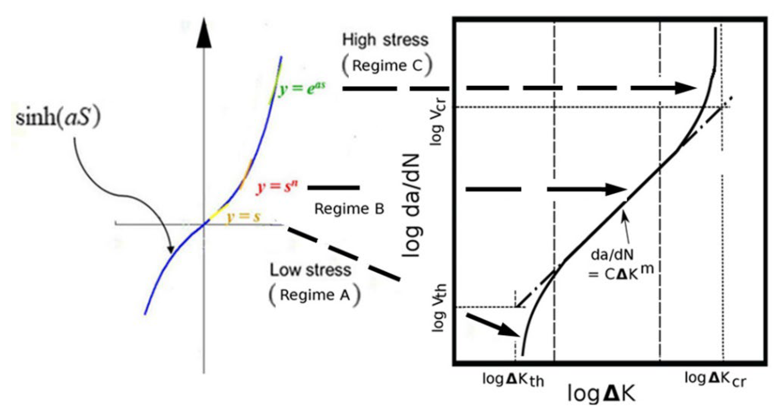
at the beginning has some linear effect;
  • S n has what is formed as a middle effect;
  • e a S 1 in the end is high.
Because an ALT in the medium range is normally carried out, Equation (17) could be expressed as:
T F = A S n e x p E a k T
As the stress quantity in the structural components is hard to calculate in parametric ALT, Equation (18) is required to state again. Because the power for numerous energy areas is expressed as the process of combining flows and effort, stresses start from effort in an energy transport system (Table 2) [32].
Stress is a material extent which defines the inner forces joining a minute portion of a continuum matter to exert to bear on each other. Because stress comes from effort in a mechanical system, we thus can utilize the parametric model. That is, Equation (18) might be restated as:
T F = A S n e x p E a k T = B e λ e x p E a k T
where A and B are quantities that do not alter their values.
To achieve the acceleration factor (AF), which might be stated as the correlation between the elevated stress quantities and usual operation circumstances, it could be altered to combine with the effort idea:
A F = S 1 S 0 n E a k 1 T 0 1 T 1 = e 1 e 0 λ E a k 1 T 0 1 T 1
As the majority of elevated testing is carried out at usual (room) temperatures, Equation (20) may be expressed as:
A F = S 1 S 0 n = e 1 e 0 λ
To attain the mission cycles of ALTs from the actual BX life on the test plan in Table 1, the sample size formulation united with Equation (20) could be expressed as follows (See Appendix A) [33].
n r + 1 × 1 x × L B * A F h a β + r
where the sample size formulation in Equation (22) may be expressed as n ~ (failure numbers + 1)·(1/accumulative failure rate)·((target lifetime/(testing plan time)) ^ β + r.
Equations (22) and (A11) as well may be confirmed as [34]. That is, for n r , sample size formulation may be stated as:
n = χ α 2 2 r + 2 2 m β l n R L = χ α 2 2 r + 2 2 m β l n R L 1 = χ α 2 2 r + 2 2 m β l n 1 F L 1 = χ α 2 2 r + 2 2 × 1 l n 1 F L 1 × L B h β
where m h / L B .
If not, for r = 0 , Equation (22) might be expressed as:
n = l n 1 C m β l n R L = l n 1 C m β l n R L = l n 1 C 1 m β l n R L 1 = l n α 1 m β l n R L 1 = χ α 2 2 2 × 1 l n 1 F L 1 × L B h β
where 2 l n α 1 = χ α 2 2 .
So, we know that Equations (23) and (24) have same formation with Equation (22).
If the life target of a mechanical product, such as the auger motor including gear system, is put to have a B1 life 10 years, the required aim cycles may be accomplished for a set of samples. We can find that the design imperfections of new product could be pinpointed and altered to fulfil the life target through parametric ALTs.

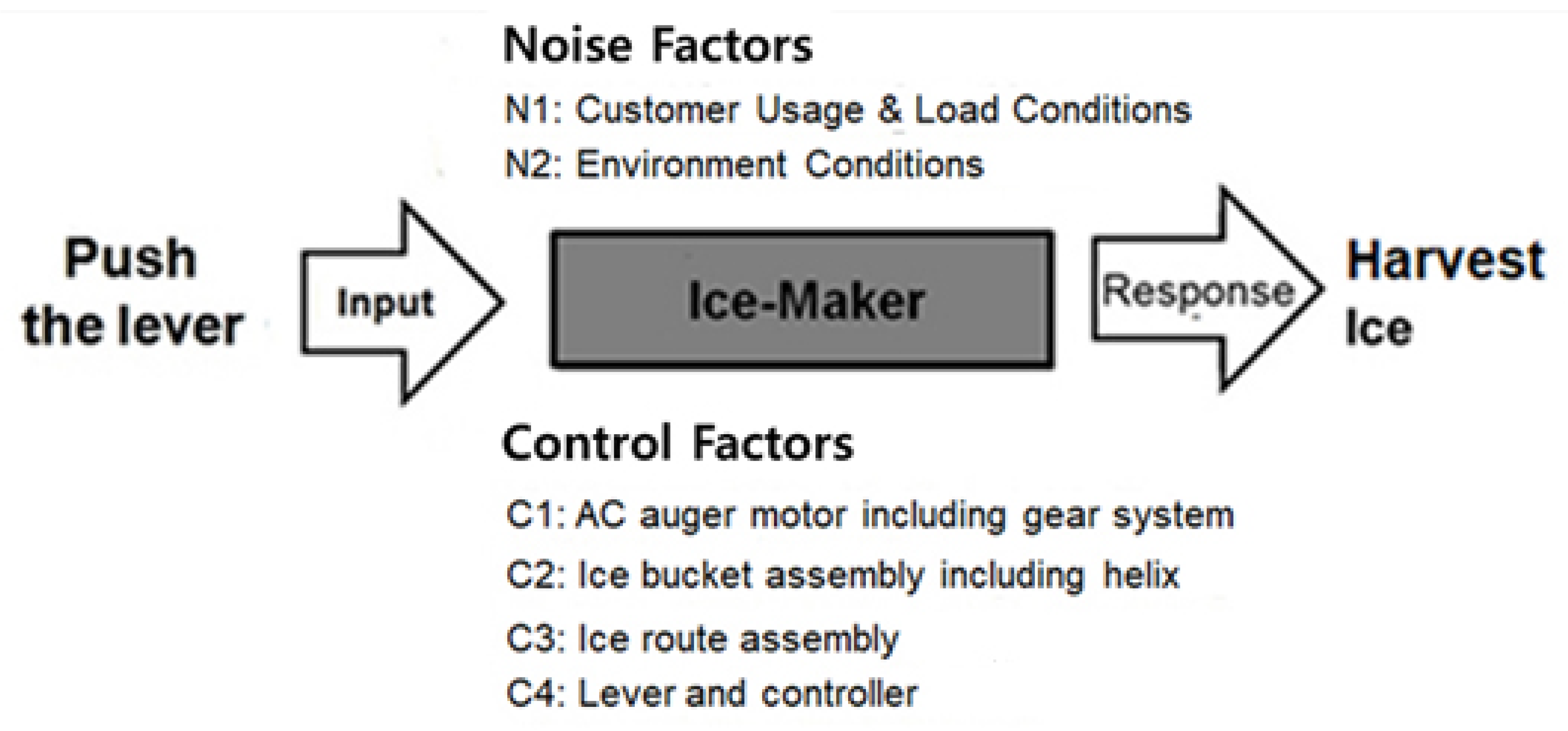
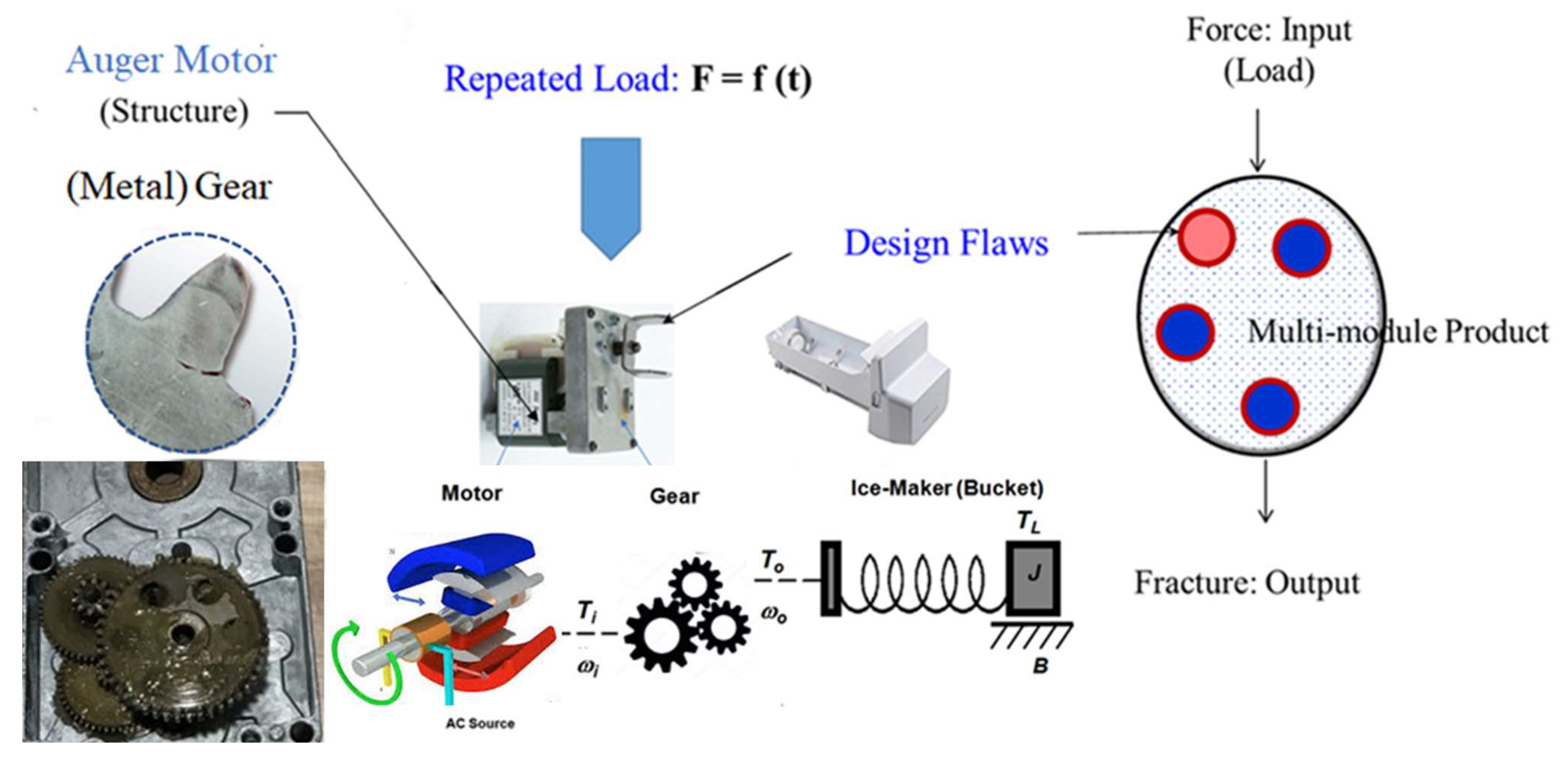
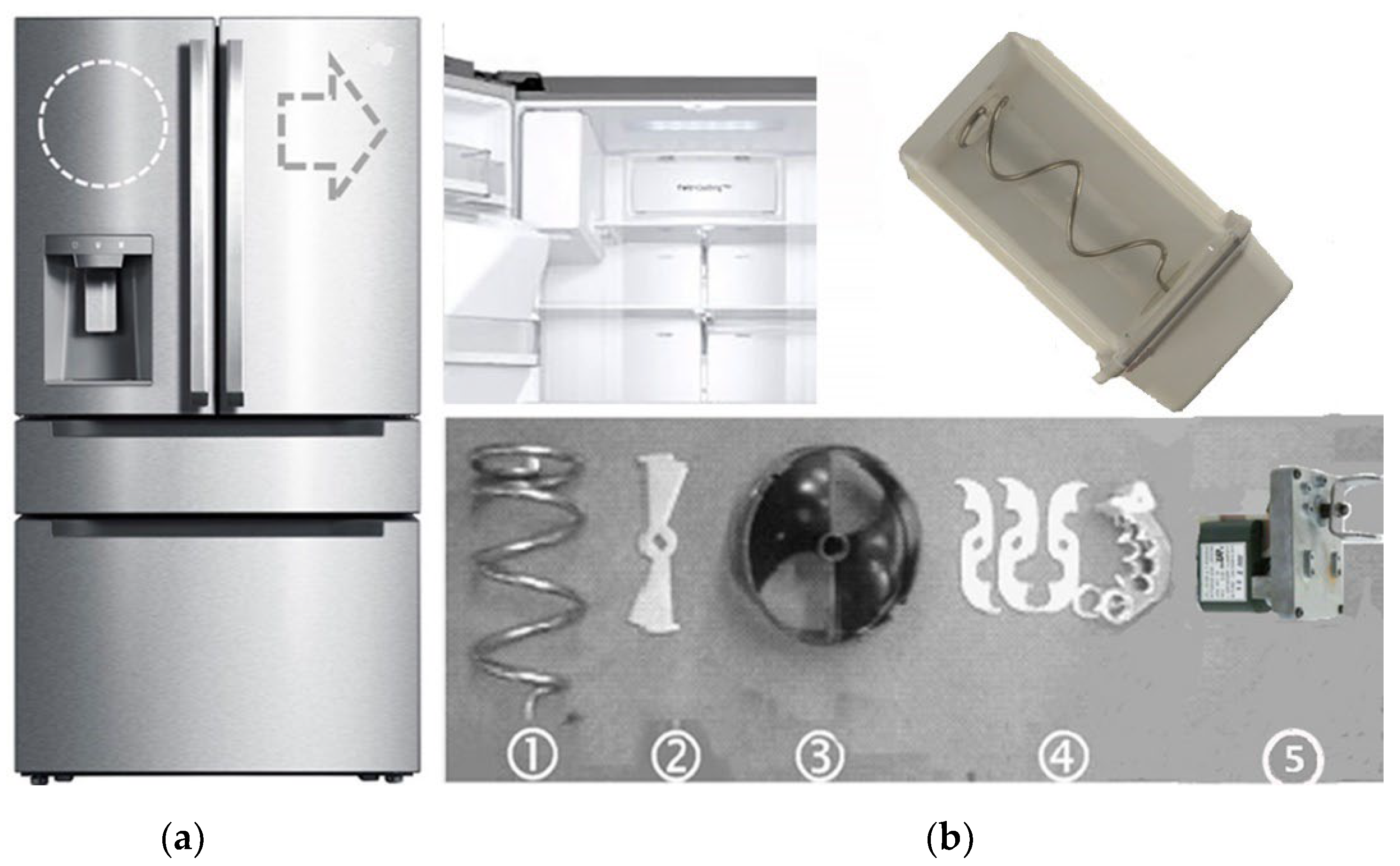
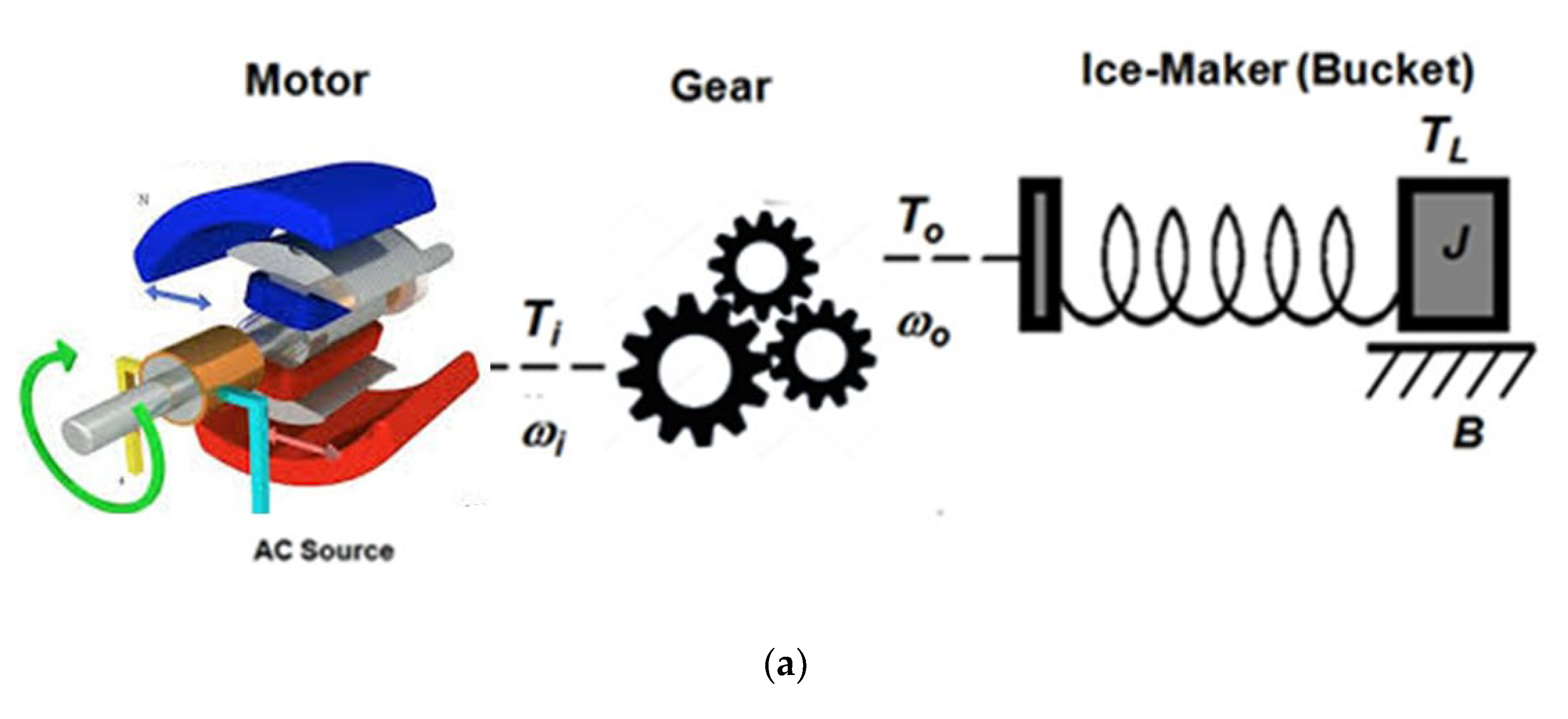
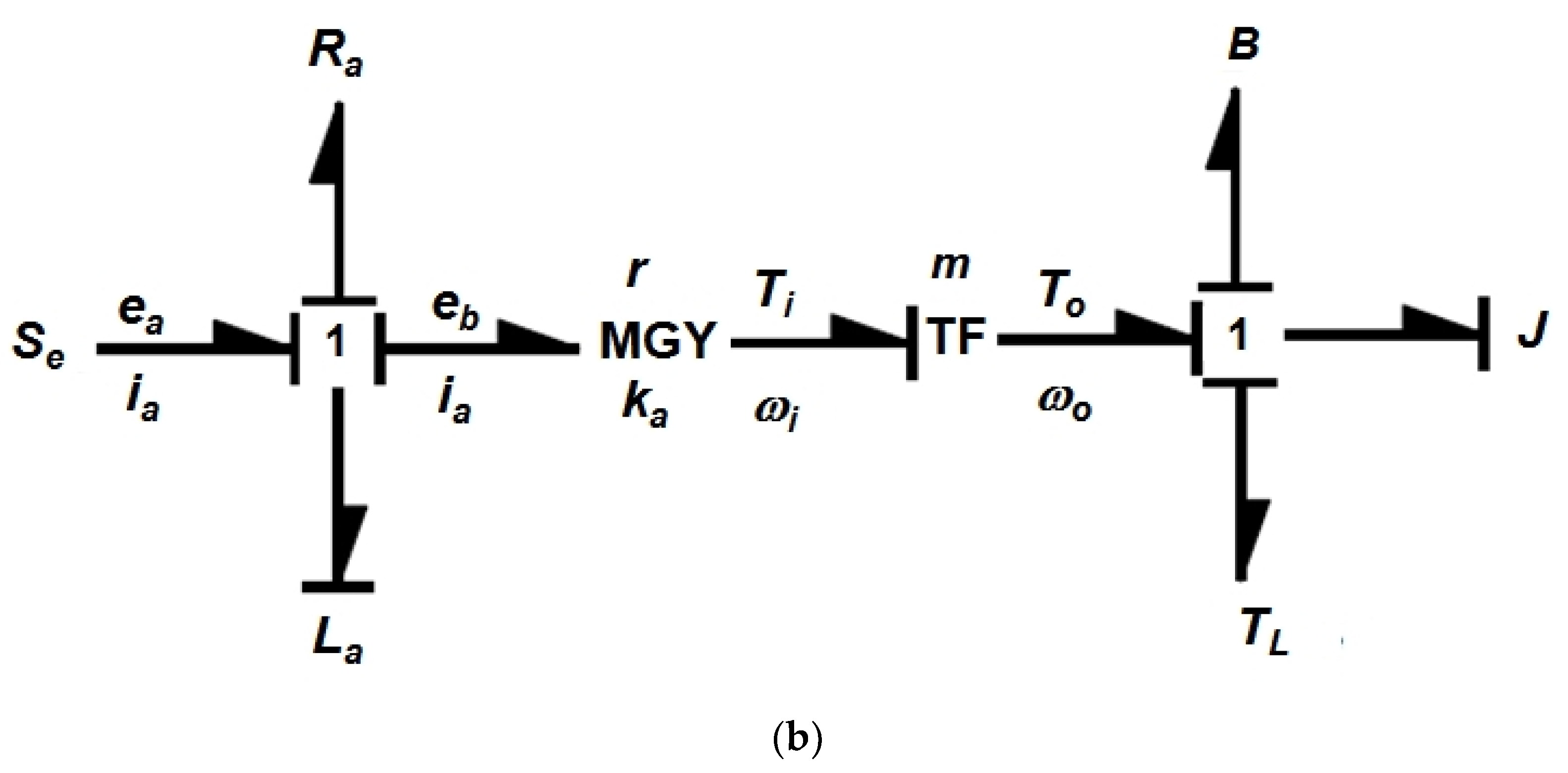
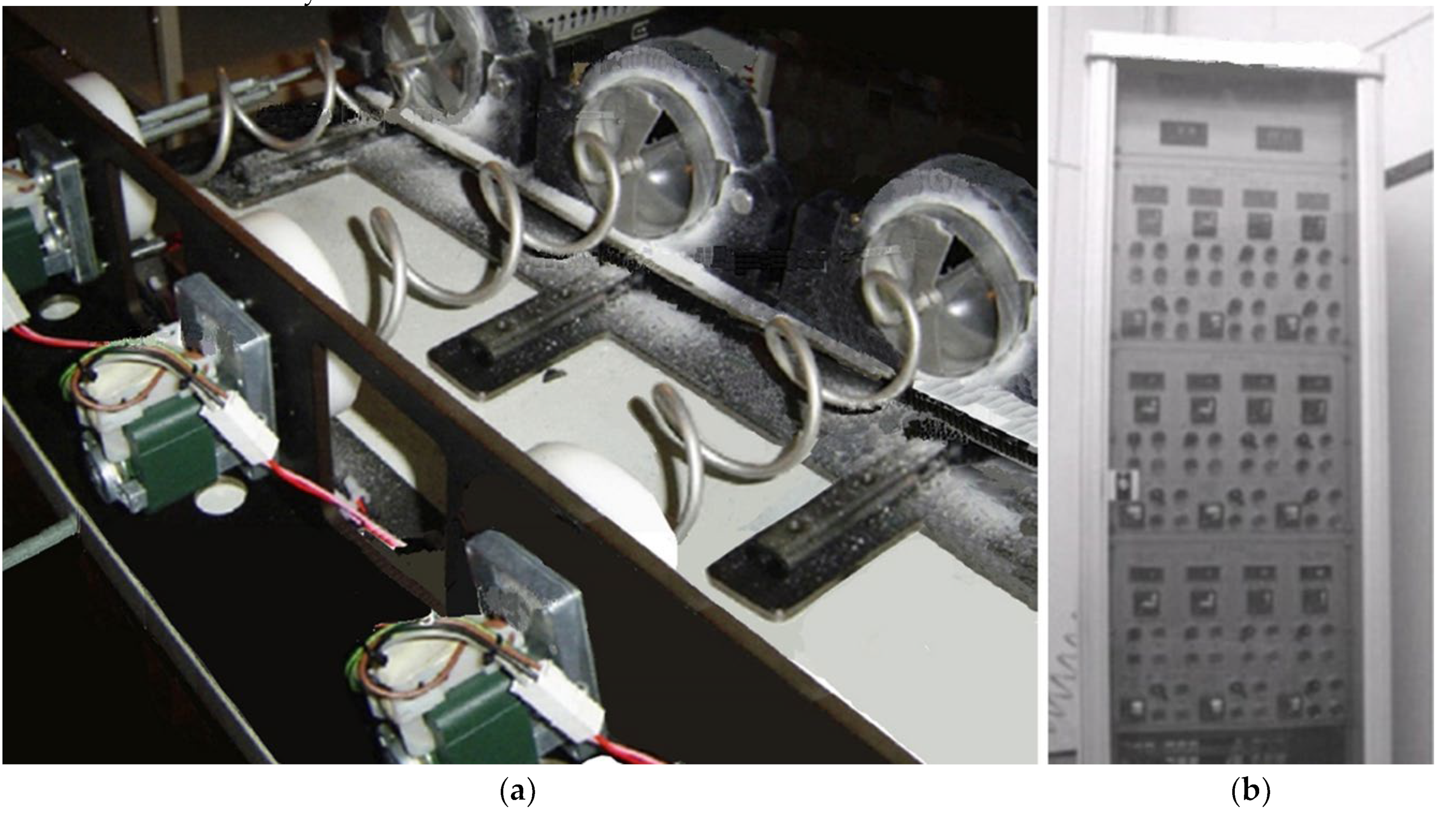
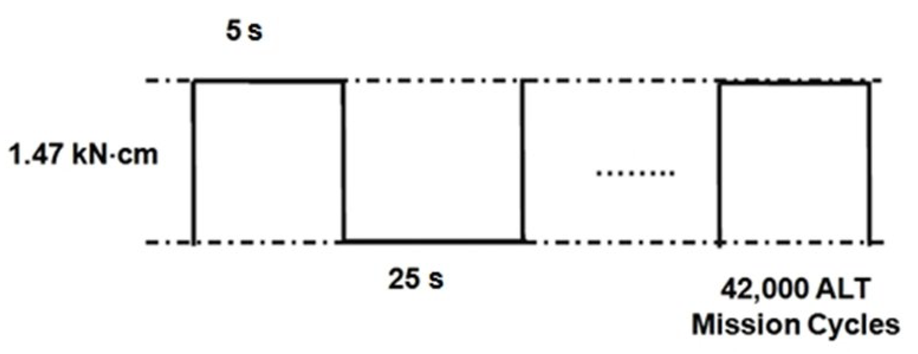
2.4. Case Study—Lifetime of a Localized Ice-Maker including Auger Motor with Gear System in a Domestic Refrigerator

As the customer wants to have an ice function in a refrigerator, an ice-maker system is equipped to produce ice. As the consumer exerts force on the lever, crushed (or cubed) ice is distributed through the route of ice. The main components in an ice-maker are made up of an auger motor including a gear system, helix support, helix upper dispenser, helix dispenser clamp, blade, blade dispenser, and bucket case, as manifested in Figure 7. They require high strength fatigue under the low temperature because of the repeated impact stress.
In the ice-making operation, the components in an ice-maker experience various mechanical loads. Domestic refrigerators in the United States are planned to harvest from 10 cubes per one usage to 200 cubes per day (20 times). As the ice-maker is repeatedly utilized in both crushed and cubed ice types, it is repeatedly subjected to (impact) loads in the ice-maker system including an auger motor with a gear system. Ice producing can additionally be affected by consumer use conditions such as ice consumption, water pressure, notch settings in refrigerator, and the number of doors open.
In the marketplace, some ice-maker components in a domestic refrigerator failed under unspecified consumer operations. Market data demonstrated that the returned products could have had design defects—improper material such as cast iron that must not be utilized under severe cold temperatures (below –20 °C) in the freezer section. So, the rotating gear systems made of cast iron repetitively impact each other while the crushed (or cubed) ice is produced. A crack (or fracture) at the root fillet and tooth end of gear may suddenly occur in the auger motor and no longer work. Engineers should find the root causes by failure analysis or reliability testing and correct them (Figure 8).
By employing the failure analysis (and laboratory tests) for returned field products, a crack that started in the fillet (or ends) of teeth in mechanical parts such as the gear propagated it to the end. To keep it functioning for its anticipated lifetime, the manufacturer was required to redesign the product for failures such as gear cracks in the auger motor. That is, if there are design flaws—such as in the gear system in the ice-maker’s auger motor—where repetitive loads are applied under severe temperature conditions, the structure will be unsuccessful in its anticipated lifetime. To reproduce the problematic part(s) and alter them, an engineer was necessitated to carry out parametric ALT for a newly designed product. It was made up to (1) a load examination for the problematic product, (2) the action of making the practical and effective use of ALTs with design modifications, and (3) the assessment of whether the lifetime objective of last designs had been fulfilled.
Figure 9 shows a schematic outline of the power transfer in an ice-making process by utilizing a bond graph formulation. To produce sufficient torque to compress forcefully so as to break the ice at the end of ice-maker, an AC auger motor supplies power by the gear system that is additionally moved to the bucket and ice crusher blade assembly. Therefore, the ice-maker system in the bucket will increase torque that has enough force and be subjected to different loads.
To obtain the governing equations that consist of state variables and utilize the mathematical work for the parametric model, the bond graph formulation in Figure 9b may be resolved at each node as follows:
d f × E 2 / d t = 1 / L a × e E 2
d f M 2 / d t = 1 / J × e M 2
where La is electromagnetic inductance.
The junction from Equation (25) is
e E 2 = e a e E 3
e E 3 = R a × f E 3
where ea is applied voltage, and Ra is electromagnetic resistance.
The junction from Equation (26) is
e M 2 = e M 1 e M 3
e M 1 = K a × i T P u l s e
e M 3 = B × f M 3
where B is viscous friction numerical quantity, and ka is the numerical quantity of the counter-electromotive force
Because f M 1 = f M 2 = f M 3 = ω and i = f E 1 = f E 2 = f E 3 = i a from Equations (27) and (28),
e E 2 = e a R a × f E 3
f E 2 = f E 3 = i a
If substituting Equations (32) and (33) into Equation (25), then
d i a / d t = 1 / L a × e a R a × i a
And from Equations (29)–(31) we can obtain
e M 2 = K a × i T L B × f M 3
i = i a
f M 3 = f M 2 = ω
If inserting Equations (35)–(37) into (26), then
d ω / d t = 1 / J × K a × i T L B × ω
We can attain the state equations from Equations (34) and (38). That is,
d i a / d t d ω / d t = R a / L a 0 m k a B / J i a ω + 1 / L a 0 e a + 1 1 / J T L
When governing equation in Equation (39) is integrated, the amount produced by the ice-maker is attained as follow:
y p = 0 1 i a ω
From Equation (39) we recognize that the life of the ice-maker relies on the torque necessitated to break the ice. As changing the torque, we can carry out the parametric ALT. That is, the life-stress formulation in Equation (19) may be altered as
T F = A S n = A T L λ = A F c × R λ = B F c λ
So, the AF in Equations (20) and (21) can be derived as
A F = S 1 S 0 n = T 1 T 0 λ = F 1 × R F 0 × R λ = F 1 F 0 λ
We can perform ALT from Equation (22) until the assigned cycles that supply the lifetime objective—B1 life 10 years—is fulfilled.
The environment circumstances of the ice-maker in a domestic refrigerator may alter from roughly −15 to −30 °C with a relative humidity varying from 0% to 20%. Relying on consumer use condition, an ice-maker utilized is a mean of roughly from three to eighteen times per day. Under the greatest usage for 10 years, it happens 65,700 use cycles.
To decide the stress quantity for parametric ALT, based on the permissible use range of the Auger motor company in bench-marked data that were attained from other chief manufacturers, we employed the step-stress life test that might assess the life under a constant use circumstance for many accelerated loads of parametric ALT such as 0.8 kN-cm, 1.0 kN-cm, and 1.47 kN-cm [35]. As the dissimilar stress level was altered because usual torque is 0.69 kN-cm, we might notice the failure cycles of the auger motor at particular stress levels.
Technical data from the auger motor manufacturer described that the usual torque was 0.69 kN-cm and greatest torque was 1.47 kN-cm. Presuming the accumulative damage exponent λ = 2, the acceleration factor was roughly five in Equation (42).
For a B1 life of 10 years, the mission cycles for ten samples (computed utilizing Equation (22)) were roughly 42,000 cycles if the shape parameter was assumed to have 2.0. This ALT was planned to secure a lifetime target—B1 life 10 years—if it might fail less than once for 42,000 cycles. Figure 10 manifests the test framework of a parametric ALT for reproducing the unsuccessful auger motor including a gear system in the market. Figure 11 manifests the duty cycles for the ice-crushing torque TL.
The assessed life LB in each ALT is stated as
L B β x n h a A F β r + 1
where ha is the actual testing cycles (or cycles).
Let x = λ LB. The estimated failure rate of the design samples λ can be described as
λ 1 L B r + 1 L B β n h a A F β
In each ALT, by quantifying the reliability from the multiplication of the estimated LB life and failure rate λ, we can ensure the reliability of the final design for a mechanical system.
The chamber apparatus was planned to cool down to a temperature of approximately −30 °C. The control console located in outside may start or cease the apparatus and may display the whole test cycles and time periods, such as test sample on/off time. To utilize the greatest ice-crushing torque TL, the helix upper dispensers with the blade dispenser were fastened jointly by a band clamper. When the controller applies the beginning signal, the equipment including the auger motor rotates. In the process, the ice-maker system will be applied with the greatest ice-crushing torque (1.47 kN-cm).
The ice-maker is generally made up of (cast, carbon, stainless, alloy, etc.) steel. The allowable stresses are expressed as a variable quantity of the tensile stress (Fu) or yield stress (Fy) of the part material. For steel, the scope of yield strength, Fy, and ultimate or tensile strength, Fu, usually utilized are 248–345 MPa and 400–483 MPa, individually [36].

3. Results and Discussion

To place a scale of stress quantity through the step-stress life test, we examined the failure cycles at the subsequent stress levels: 8 kN-cm, 1.0 kN-cm, and 1.47 kN-cm (torque for parametric ALT), which may be attained from the bolted force of a band clamper with the helix upper dispenser. For 0.8 kN-cm, the ice-maker stopped near 12,000 cycles. For 1.0 kN-cm, the ice-maker stopped near 10,000 cycles and 12,000 cycles. On the other hand, for 1.47 kN-cm, the ice-maker stopped near 6000 cycles and 7000 cycles. Thus, we resolved the stress level as 1.47 kN-cm for ALT because it had a relatively fine data linearity on the Weibull plot, contrasted from the other stress levels.
In the first ALT, the teeth of gear system in the auger motor fractured near 6000 cycles, 6900 cycles, 8500 cycles, and 8700 cycles when ice-makers were broken down in the failed samples. Figure 12 manifests a picture contrasting the product returned from the market and that from the first ALT, separately. Using a stereomicroscope, we also observed the fractured surface at the first ALT. It showed fatigue crack and mechanical fracture. As they were alike in form, through parametric ALT we might reproduce the fractured gear system in the marketplace, there was a material design flaw—a cast iron which cannot be endured under the cold temperatures (−20 °C below) in the freezer section. As the gear teeth (cast iron) repeatedly struck each other, they started to crack and finally fractured because this material was brittle under these conditions. Figure 13 manifests the graphic examination of the ALT consequences and market data on a Weibull plot. The shape parameter in the first ALT that depended on load conditions was approximated to have 2.0. For the last design, the shape parameter was confirmed to have 4.38 on the Weibull plot.
To endure repeated impact loads, the material of the problematic gear system used in the market was altered from cast iron (carbon, 3 wt% and silicon, 2 wt%) to a sinter-hardened powder metallurgy nickel steel.
In the second ALT, near 9900 cycles and 12,000 cycles, the fracturing and cracking of helix made of polycarbonates (PC) occurred in the contact region of the blade dispenser (Figure 14). To identify the root cause of the unsuccessful system, we checked the failed product. We found that there was a structural design defect—the weld line between the blade dispenser and the helix upper dispenser, which had numerous micro-voids that were produced in the process of plastic injection. When the blade dispenser made of stainless steel hit the helix upper dispenser made of plastic under severe cold conditions, it cracked and fractured near the weld line (Figure 14b). As a modification, we added reinforced rib on the side and front of the helix. After that, finite element analysis (FEA), which can be combined with parametric ALT, was performed. As the helix upper dispenser was fixed against the wall, the straightforward impact loads (1.47 kN-cm), as seen in Figure 14, were exerted. Using materials and processing conditions similar to those of the helix upper dispenser, the constitutive properties of the materials such as polycarbonates (helix structure) were determined. As a result, the mechanical concentrated stress of the samples through finite element examination was decreased from 36.9 kPa to 21.3 kPa.
As the material of gear was altered and reinforced rib on front and side of helix upper dispenser was added, the life of the ice-maker including an auger motor with gear teeth was extended. However, because the ice-maker system had insufficient fatigue strength for repeated impact stress, 42,000 mission cycles in the second ALT yet were not satisfied. So, we carried out a third ALT to confirm the design of the ice-maker.
In the third ALT, there were no issues until 42,000 cycles. Over the route of three ALTs with design modifications, the auger motor including gear system was established to be B1 life 10 years with an accumulated failure rate of 1% from Equations (43) and (44). Figure 15 and Table 3 represent an abridged result of the ALTs.

4. Summary and Conclusions

To increase the lifespan of a mechanical product such as an auger motor including a gear system, which was used in a refrigerator ice-maker and returned from the market, we adopted a reliability methodology that included a (generalized) life-stress description by a transport process and a sample size equation. It included the following: (1) the product BX life shaped the parametric ALT plan, (2) parametric ALTs with alternations, and (3) determination if the system design attained the desired number of assigned cycles. Ice-maker system including auger motor was investigated as a case study.
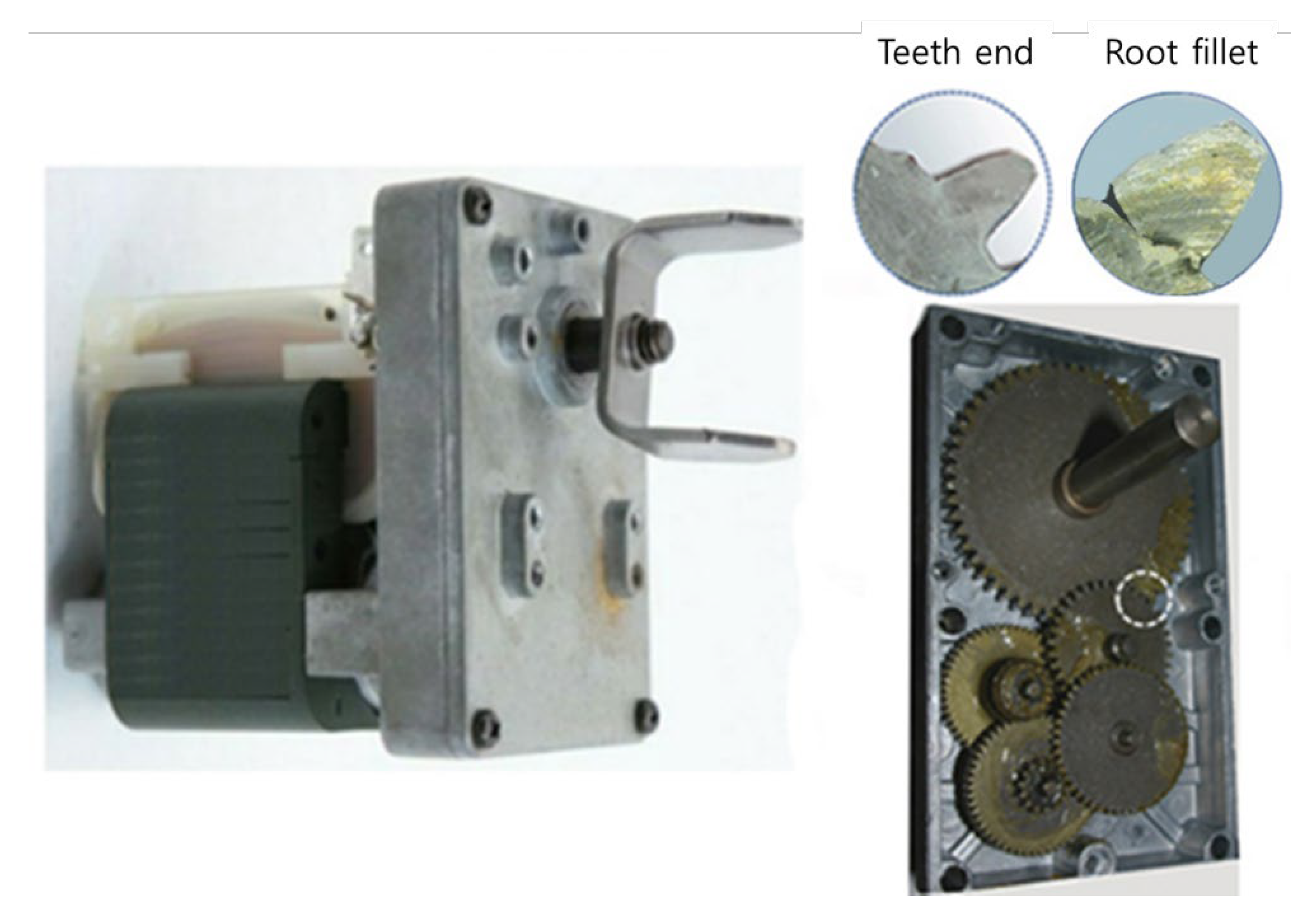
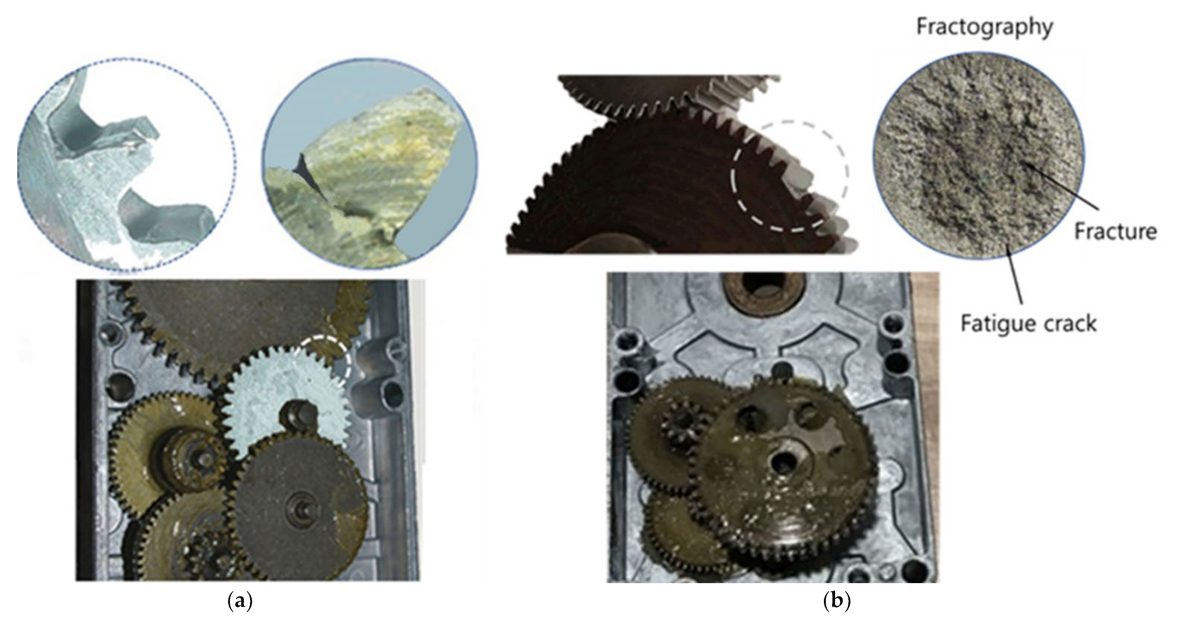
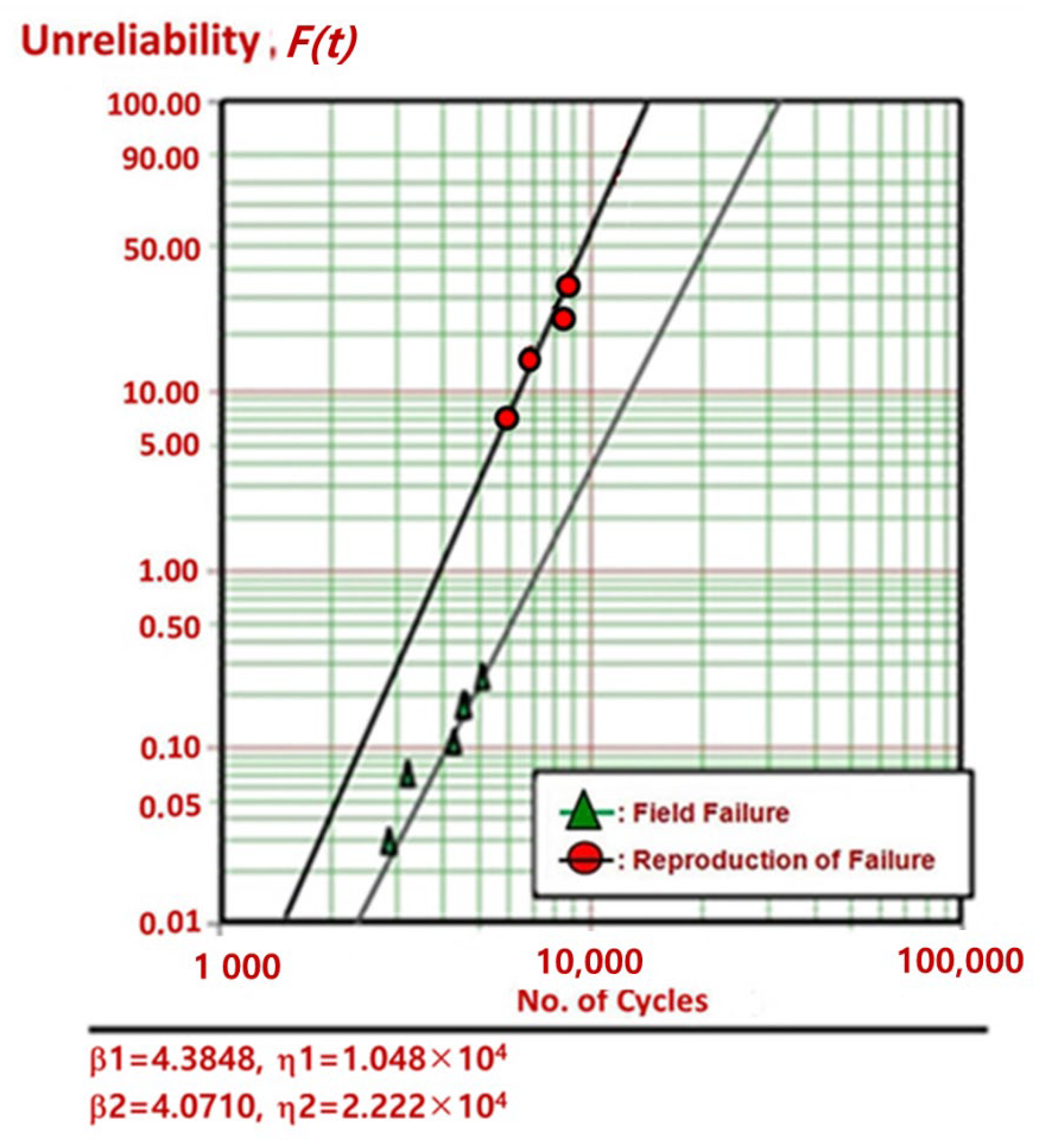
  • In the first ALT, the auger motor (n = 10) made stopped near 6000 cycles, 6900 cycles, 8500 cycles, and 8700 cycles when applied for impact torque 1.47 kN-cm. After disassembling four problematic samples, we found that the teeth of gear system in the auger motor fractured. The gear material in a refrigerator ice-maker was modified from cast iron (carbon, 3 wt% and silicon, 2 wt%) to a sinter-hardened powder metallurgy nickel steel.
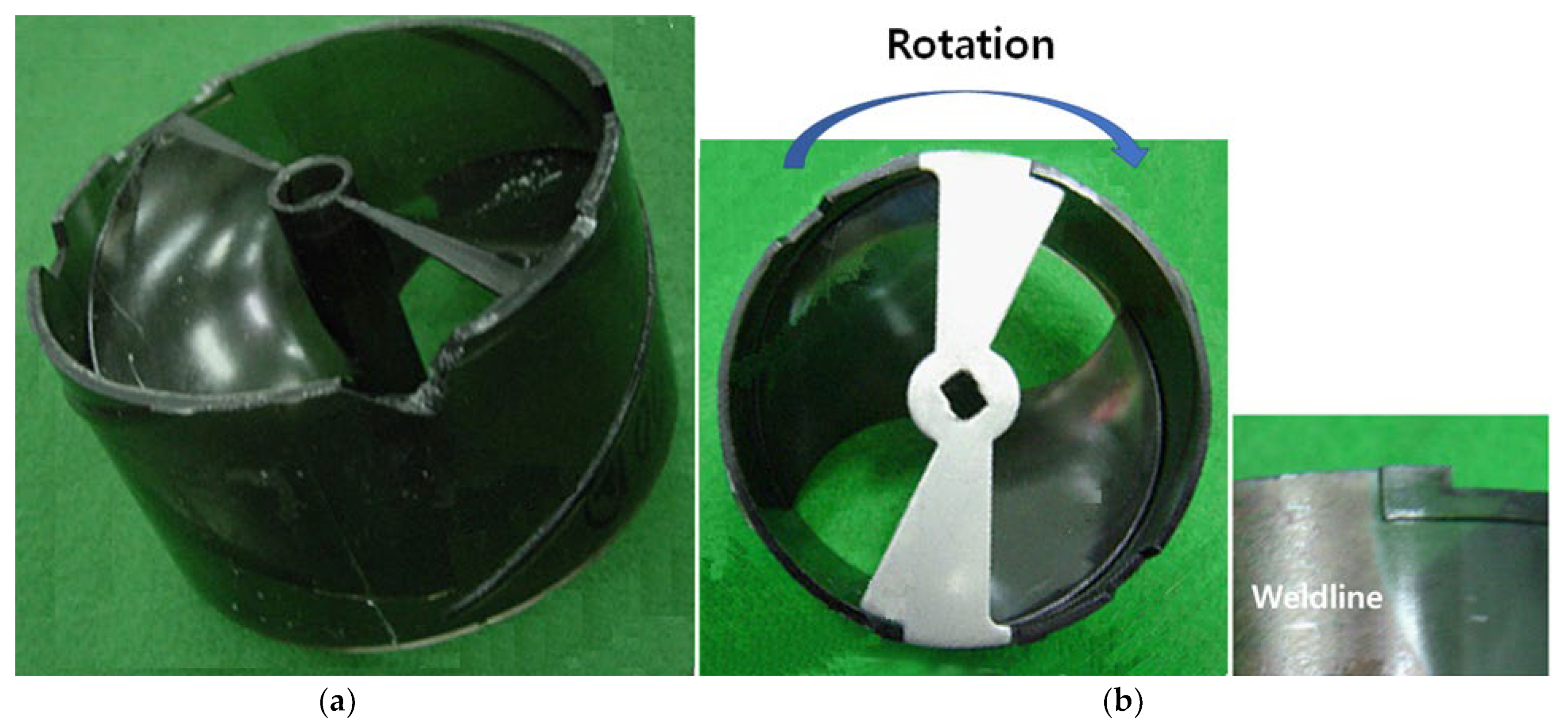
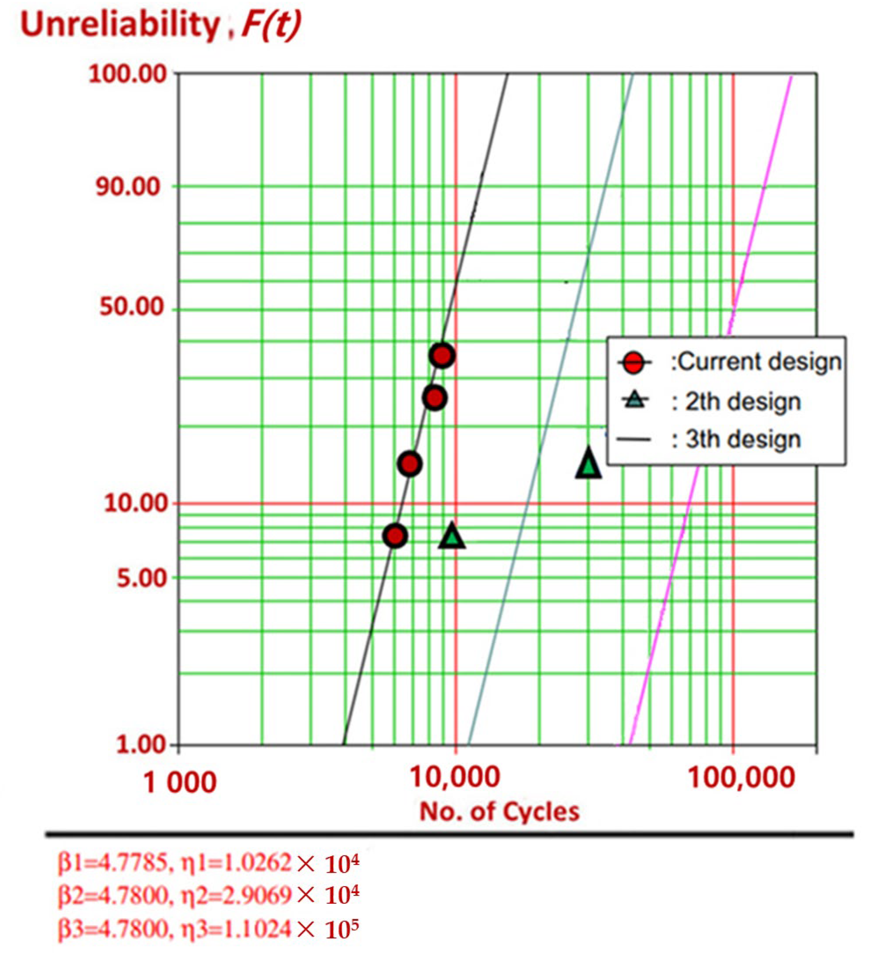
  • In the second ALT, we discovered the fractured helix made of polycarbonates (PC) at 9900 cycles and 12,000 cycles because the ice-maker system did not have enough fatigue strength for repeated impact stress in the freezer section. As an alternation, a strengthened rib on the side and front of the helix was added.
  • During the third ALT, no issues were discovered. The ice-maker including an auger motor might fulfil the life target—B1 life 10 years. By examining problematical market products and conducting parametric ALTs with design alternations, it could enhance the lifetime of an auger motor including a gear system in a refrigerator ice-maker.
  • By understanding the design issues returned for field products, we might perform parametric ALTs with design alternations. After reproducing the field failures, we could alter them. Eventually, we estimated if the product fulfilled the life objectives. In the meantime, we used the (generalized) time-to-failure model and sample size formulation.
This methodology has been applicable to other mechanical products and, as demonstrated here, was effective in improving the reliability of the auger motor including a gear system. It should be applicable to other mechanical systems. Designers need to understand why multi-module products are unsuccessful during their life. If there are design defects in the newly designed module structures and these are subjected to repetitive (impact) loads during its functioning, the product may be unsuccessful before its anticipated lifetime. Engineers might be needed to recognize the (dynamic) loading of a mechanical system so that the accelerated testing expressed as the proportion of greatest stress in contrast to minimum stress may be performed until the required mission cycles (reliable quantitative specification) are obtained from the sample size formulation. In the meantime, parametric ALT may be used to identify the design issues of systems and modify them.

Author Contributions

S.W. carried out the concept evolving, methodology, examination, and experiment and wrote the draft. D.L.O. checked the study and wrote down the original document. Y.M.H. modified the draft. All authors have comprehended and agreed to the prepared and issued version of the document. All authors have read and agreed to the published version of the manuscript.

Funding

This study received no external funding.

Data Availability Statement

The data provided in this investigation may be obtained on request from the corresponding author.

Conflicts of Interest

The authors declare no conflict of interest.

Abbreviations

BXTime that is a cumulated failure rate of X%: durability index
EaActivation energy, eV
eEffort
ebCounter-electromotive force
efField voltage, V
fFlow
FcIce crushing force, kN
F(t)Unreliability
hTesting time (or cycles)
h*Non-dimensional testing cycles, h * = h / L B 1
ifField current, A
JMomentum of inertia, kg m2
kBoltzmann’s numerical quantity, 8.62 × 10⁻⁵ eV/deg
LBTarget BX life and x = 0.01 X, on the circumstances that x ≤ 0.2
mGear ratio
MGYGyrator in causal forms for basic 2-ports and 3-ports
nNumber of test samples
QLevel of energy absorbed or released during the reaction. For the semiconductor, whole number of dopants per unit area
RProportion for minimum stress to maximum stress in stress cycle, σmin/σmax
rUnsuccessful numbers
rCoefficient of gyrator
SStress
TTemperature, K
tiTest time for each sample
TFTime to failure
TLIce-crushing torque in bucket, kN cm
XCumulated failure rate, %
xx = 0.01 X, on condition that x ≤ 0.2.
Greek symbols
ξElectrical field applied
ηCharacteristic life
λCumulative damage quantity in Palmgren–Miner’s rule
χ2Chi-square distribution
αConfidence level
ωAngular velocity in ice bucket, rad/s
Superscripts
βShape parameter in Weibull distribution
nStress dependence, n = l n ( T f ) l n ( S ) T
Subscripts
0Usual stress conditions
1Elevated stress conditions

Appendix A. Deriving Sample Size Formulation

If the product follows Weibull distribution, the cumulated failure rate F(t) is stated as:
F t = 1 e t η β
where t is time, η is characteristic life, and β is shape parameter.
As t = LB in Equation (A1), the connection between BX life, LB, and characteristic life, η, may be stated as:
L B β = l n 1 1 x × η β
where x = 0.01 F(t).
For estimating lifetime, shape parameter is greater than one. The Weibayes method is defined as Weibull Analysis with a given shape parameter. The shape parameter is assumed from previous experience, real experimental data. In choosing the model parameters, the maximum likelihood estimation (MLE) in statistics is a common method of assessing the parameters of a model. The characteristic life, ηMLE, can be defined as:
η M L E β = i = 1 n t i β r
where η M L E is the maximum likelihood estimate, n is the entire number of selected samples, t i is the testing time for each sample, and r is the failure number.
To estimate characteristic life, η, in Equation (A2), the Weibayes model is a commonly accepted way of examining reliability data. In other words, if the entire cases as failures (r ≥ 1) and no failures (r = 0) need to be divided, we can estimate the characteristic life. That is, if the failure numbers, r, are greater than or equal to 1 and the confidence level is 100 (1–α), the characteristic life, ηα, may be approximated from Equation (A3).
η α β = 2 r χ α 2 2 r + 2 × η M L E β = 2 χ α 2 2 r + 2 × i = 1 n t i β     for   r   1
where χ α 2 () is the chi-square distribution when the p-value is α.
Assuming there are no unsuccessful numbers, ln (1/α) is alike to the chi-square value, χ α 2 2 2 .
p v a l u e : α = χ α 2 2 e x 2 x ν 2 1 2 ν 2 Γ ν 2 d x = 2 l n α 1 e x 2 x ν 2 1 2 ν 2 Γ ν 2 d x   for   x     0
where Γ is the gamma function and ν is the shape parameter.
For r = 0, the characteristic life ηα from Equation (A4) may be stated as:
η α β = 2 χ α 2 2 × i = 1 n t i β = 1 l n 1 α × i = 1 n t i β
As Equation (A4) is proven for whole cases r ≥ 0, characteristic life, ηα, may be defined as:
η α β = 2 χ α 2 ( 2 r + 2 ) × i = 1 n t i β   for   r   0
If the assessed characteristic life of the p-value α, ηα, in Equation (A7), is put into Equation (A2), we can attain the BX life formulation:
L B β = ln 1 1 x × 2 χ α 2 ( 2 r + 2 ) × i = 1 n t i β
As entire reliability testing has inadequate sample numbers to estimate the life for the assigned failures, which may be less than that of the samples, the test scheme may be defined as:
n h β t i β n r × h β
If Equation (A8) is altered with Equation (A9), the BX life equation may be defined as:
L B β ln 1 1 x × 2 χ α 2 ( 2 r + 2 ) n h β l n 1 1 x × 2 χ α 2 ( 2 r + 2 ) × n r h β L B * β
If Equation (A10) is rearranged, the sample size formulation with the failures may be restated as:
n χ α 2 ( 2 r + 2 ) 2 × 1 l n 1 1 x × L B * h β + r
Because χ α 2 2 r + 2 2 r + 1 for α = 0.6 and   l n 1 x 1 = x + x 2 2 + x 3 3 + x , the sample size Equation (A11) may be uncomplicated adjoining to:
n r + 1 × 1 x × L B * h β + r
where the sample size formulation may be expressed as n ~ (failure numbers + 1)·(1/cumulative failure rate)·((target lifetime/(plan testing time)) ^ β + r.
To attain the task cycle of ALTs from the objective BX lifetime on the test scheme in Table 1, the sample size formulation integrated with Equation (13) may be stated as follows:
n r + 1 × 1 x × L B * A F h a β + r
where the sample size equation can be stated as n ~ (failure numbers + 1)·(1/cumulative failure rate)·((target lifetime/(plan testing time)) ^ β + r.

References

  1. Bigg, G.; Billings, S. The iceberg risk in the Titanic year of 1912: Was it exceptional? Significance 2014, 11, 6–10. [Google Scholar] [CrossRef]
  2. ISO 1328-2:2020; Cylindrical Gears—ISO System of Flank Tolerance Classification—Part 2: Definitions and Allowable Values of Double Flank Radial Composite Deviations: General Procedures. ISO: Geneva, Switzerland, 2020.
  3. ISO 17804:2020; Founding—Ausferritic Spheroidal Graphite Cast Irons—Classification Cylindrical Gears. ISO: Geneva, Switzerland, 2020.
  4. AGMA 939-A07; Austempered Ductile Iron for Gears. AGMA Information Sheet: Alexandria, VA, USA, 2018.
  5. DVB Bank SE Aviation Research (AR). An Overview of Commercial Jet Aircraft 2013; DVB Bank SE Aviation Research (AR): Schiphol, The Netherlands, 2014; p. 20. [Google Scholar]
  6. Woo, S.; Pecht, M.; O’Neal, D. Reliability design and case study of the domestic compressor subjected to repetitive internal stresses. Reliab. Eng. Syst. Saf. 2019, 193, 106604. [Google Scholar] [CrossRef]
  7. Duga, J.J.; Fisher, W.H.; Buxaum, R.W.; Rosenfield, A.R.; Buhr, A.R.; Honton, E.J.; McMillan, S.C. The Economic Effects of Fracture in the United States; Final Report; Available as NBS Special Publication 647-2; Battelle Laboratories: Columbus, OH, USA, 1982. [Google Scholar]
  8. Modarres, M.; Kaminskiy, M.; Krivtsov, V. Reliability Engineering and Risk Analysis: A Practical Guide, 3rd ed.; CRC Press: Boca Raton, FL, USA, 2016. [Google Scholar]
  9. Elsayed, E.A. Reliability Engineering; John Wiley & Sons: Hoboken, NJ, USA, 2012. [Google Scholar]
  10. Hahn, G.J.; Meeker, W.Q. How to Plan an Accelerated Life Test (E-Book); ASQ Quality Press: Milwaukee, WI, USA, 2004. [Google Scholar]
  11. Moura, E.C. How to Determine Sample Size and Estimate Failure Rate in Life Testing; ASQ Quality Press: Milwaukee, WI, USA, 2004. [Google Scholar]
  12. McPherson, J. Reliability Physics and Engineering: Time-to-Failure Modeling; Springer: New York, NY, USA, 2010. [Google Scholar]
  13. Griffith, A.A. The phenomena of rupture and flow in solids. Philos. Trans. R Soc. Lond. A 1921, 221, 163–198. [Google Scholar]
  14. Wang, Y.; He, Z. Experimental and Statistical Study of the Fracture Mechanism of Sn96.5Ag3Cu0.5 Solder Joints via Ball Shear Test. Materials 2022, 15, 2455. [Google Scholar] [CrossRef] [PubMed]
  15. Anderson, T.L. Fracture Mechanics—Fundamentals and Applications, 3rd ed.; CRC: Boca Raton, FL, USA, 2017. [Google Scholar]
  16. ASTM E606/E606M; Standard Test Method for Strain-Controlled Fatigue Testing. ASTM International: West Conshohocken, PA, USA, 2019.
  17. ASTM E399; Standard Test Method for Linear-Elastic Plane-Strain Fracture Toughness of Metallic Materials. ASTM International: West Conshohocken, PA, USA, 2020.
  18. ASTM E647; Standard Test Method for Measurement of Fatigue Crack Growth Rates. ASTM International: West Conshohocken, PA, USA, 2015.
  19. ASTM E739-10; Standard Practice for Statistical Analysis of Linear or Linearized Stress-Life (S-N) and Strain-Life (ε-N) Fatigue Data. ASTM International: West Conshohocken, PA, USA, 2015.
  20. Elishakoff, I. Stepan Prokofievich Timoshenko and America. ZAMM—J. Appl. Math. Mech. 2019, 99, e201800338. [Google Scholar] [CrossRef]
  21. David, J.G. Introduction to Quantum Mechanics, 3rd ed.; Cambridge University Press: Cambridge, UK, 2018. [Google Scholar]
  22. Cemal, B. Introduction to Unified Mechanics Theory with Applications, 1st ed.; Springer Nature: Berlin/Heidelberg, Germany, 2021. [Google Scholar]
  23. Weingart, R.G.; Stephen, P. Timoshenko: Father of Engineering Mechanics in the U.S. Structure Magazine, 1 August 2007. [Google Scholar]
  24. Reddy, J.N. An Introduction to the Finite Element Method, 4th ed.; McGraw-Hill: New York, NY, USA, 2020. [Google Scholar]
  25. Dyniewicz, B.; Bajkowski, J.M.; Bajer, C.I. Effective Viscoplastic-Softening Model Suitable for Brain Impact Modelling. Materials 2022, 15, 2270. [Google Scholar] [CrossRef] [PubMed]
  26. Vijaya Kumar, S.D.; Karuppanan, S.; Ovinis, M. Artificial Neural Network-Based Failure Pressure Prediction of API 5L X80 Pipeline with Circumferentially Aligned Interacting Corrosion Defects Subjected to Combined Loadings. Materials 2022, 15, 2259. [Google Scholar] [CrossRef] [PubMed]
  27. Vega, M.A.; Todd, M.D. A variational Bayesian neural network for structural health monitoring and cost-informed decision-making in miter gates. Struct. Health Monit. 2022, 21, 4–18. [Google Scholar] [CrossRef]
  28. IEEE Standard Glossary of Software Engineering Terminology. IEEE STD 610.12-1990. Standards Coordinating Committee of the Computer Society of IEEE. (REAFFIRMED SEPTEMBER 2002). Available online: https://ieeexplore.ieee.org/document/159342 (accessed on 31 December 2020).
  29. Kreyszig, E. Advanced Engineering Mathematics, 10th ed.; John Wiley and Son: Hoboken, NJ, USA, 2011; p. 683. [Google Scholar]
  30. Grove, A. Physics and Technology of Semiconductor Device, 1st ed.; Wiley International Edition: New York, NY, USA, 1967; p. 37. [Google Scholar]
  31. Minges, M.L. Electronic Materials Handbook; ASM International: Cleveland, OH, USA, 1989; Volume 1, p. 888. [Google Scholar]
  32. Karnopp, D.C.; Margolis, D.L.; Rosenberg, R.C. System Dynamics: Modeling, Simulation, and Control of Mechatronic Systems, 6th ed.; John Wiley & Sons: New York, NY, USA, 2012. [Google Scholar]
  33. Woo, S.; O’Neal, D.L. Reliability design and case study of mechanical system like a hinge kit system in refrigerator subjected to repetitive stresses. Eng. Fail. Anal. 2019, 99, 319–329. [Google Scholar] [CrossRef]
  34. Wasserman, G. Reliability Verification, Testing, and Analysis in Engineering Design; Marcel Dekker: New York, NY, USA, 2003; p. 228. [Google Scholar]
  35. Tang, L.C. Multiple-steps step-stress accelerated life tests: A model and its spreadsheet analysis. Int. J. Mater. Prod. Technol. 2004, 21, 423–434. [Google Scholar] [CrossRef]
  36. William, E.L.; David, M.; Christoper, N.M.; Stephen, W.B.; Richard, J.F.; Timothy, F.; Thomas, A.S.; Frank, W.G. Mechanical Properties of Structural Steels; NIST NCSTAR 1-3D; NIST: Gaithersburg, MD, USA, 2005.
Figure 1. System life resolved by new subsystem (or module): (a) a systematic classes of multi-module refrigerator; (b) product life LB.
Applsci 12 07484 g001
Figure 2. Lifetime index and BX life (LBX) on the bathtub.
Applsci 12 07484 g002
Figure 3. Intended function of ice-maker adding gear system (instance).
Applsci 12 07484 g003
Figure 4. Fatigue failure on the structural component produced by repetitive (impact) load and design imperfections.
Applsci 12 07484 g004
Figure 5. Potential variation in material—silicon—when electromagnetic field is applied: (a) initial stage; (b) final stage.
Applsci 12 07484 g005
Figure 6. Sine hyperbolic stress expression in contrast to Paris law from a viewpoint of stress span.
Applsci 12 07484 g006
Figure 7. A domestic refrigerator with ice-maker. (a) French-door refrigerator; (b) machine components in an ice-maker: helix support ①, blade dispenser ②, helix upper dispenser ③, blade ④, and auger motor ⑤.
Applsci 12 07484 g007
Figure 8. Damaged auger motor after usage.
Applsci 12 07484 g008
Figure 9. Design idea of an ice-maker system. (a) Illustrative drawing of auger motor, ice crusher, ice bucket, etc. (b) Bond graph formulation of ice-maker.
Applsci 12 07484 g009aApplsci 12 07484 g009b
Figure 10. Apparatus utilized in parametric ALT. (a) ALT apparatus; (b) controller.
Applsci 12 07484 g010
Figure 11. Duty cycles of the ice-crushing torque TL applied on the band clamper.
Applsci 12 07484 g011
Figure 12. Failed gear systems. (a) Unsuccessful product in the market; (b) fractured product after the first ALT.
Applsci 12 07484 g012
Figure 13. Unsuccessful products on the Weibull plot: failed products at the market and failed products after first ALT.
Applsci 12 07484 g013
Figure 14. Unsuccessful products after the 2nd ALT: (a) unsuccessful products in the 2nd ALT, (b) the root cause of 2nd ALT failure.
Applsci 12 07484 g014
Figure 15. Consequence of parametric ALT on Weibull plot.
Applsci 12 07484 g015
Table 1. Comprehensive ALT scheme of mechanical modules (or subsystems) in a product such as refrigerator.
ModulesField DataExpected ReliabilityIntended Reliability
Failure Rate Per Year, λ (%/Year)BX Life,
LB (Year)
Failure Rate Per Year,
λ (%/Year)
BX Life,
LB (Year)
Failure Rate Per Year,
λ (%/Year)
BX Life,
LB (Year)
A0.303.3The same×10.303.330.1010(BX = 1.0)
B0.352.9The same×10.352.90.1010(BX = 1.0)
C0.244.2New×51.200.830.1010(BX = 1.0)
D0.156.7Adjusted×20.303.330.1010(BX = 1.0)
E0.313.2Adjusted×20.621.610.1010(BX = 1.0)
Others (F/G/H)0.5010.0The same×10.5010.00.5010(BX = 5.0)
System1.92.9 3.270.831.0010(BX = 10)
Table 2. Power stated as effort and flow in an energy transport system.
System FeaturePower, e(t) × f(t)Effort, e(t)Flow, f(t)
TranslationF × VForce, F(t)Velocity, V(t)
RotationΤ × ωTorque, τ(t)Angular velocity, ω(t)
Pump, compressorP × QPressure difference, ∆P(t)Volume flow rate, Q(t)
ElectricV × iVoltage, V(t)Current, i(t)
Magneticem × φMagneto-motive force, em(t)Magnetic flux, φ(t)
Table 3. ALT outcomes for ice-maker including auger motor with gear system.
Parametric ALT1st ALT2nd ALT3rd ALT
Draft Design Final Design
Over the course of 42,000 cycles, the gear system has no problems6000 cycles: 1/10 fracture
6900 cycles: 1/10 fracture
8500 cycles: 1/10 fracture
8700 cycles: 1/10 fracture
(Failed gear samples)
9900 cycles: 1/10 fracture
12,000 cycles: 1/10 fracture
(Failed helix samples)
42,000 cycles: 10/10 OK
Structure Applsci 12 07484 i001 Applsci 12 07484 i002
Action plansC1: material: from cast iron to a sinter-hardened powder steelC2: added reinforced rib on side and front of helix
Publisher’s Note: MDPI stays neutral with regard to jurisdictional claims in published maps and institutional affiliations.

