Article

Analysis of the Influence of a Powertrain Mounting System on a Dual-Clutch Transmission Vehicle under Typical Working Conditions

State Key Laboratory of Mechanical Transmissions, Chongqing University, Chongqing 400044, China
*
Author to whom correspondence should be addressed.
Appl. Sci. 2022, 12(15), 7439; https://doi.org/10.3390/app12157439
Submission received: 16 June 2022 / Revised: 15 July 2022 / Accepted: 17 July 2022 / Published: 25 July 2022
(This article belongs to the Topic Dynamical Systems: Theory and Applications)

Abstract

:
The unsuitably designed powertrain mount may cause jittering and shrugging during the starting and shifting processes of the vehicle, which seriously affects the comfort of using the vehicle. However, the influence of mounts on vehicles has been neglected in previous studies. In view of the above problems, this study establishes a DCT vehicle coupling dynamic model, considering six degrees of freedom of the powertrain mount and the engine dynamic torque, nonlinear characteristics of a dual-mass flywheel, time-varying stiffness of gear systems, and other factors. Furthermore, the effect of mounts on the longitudinal dynamic characteristics of the vehicle is studied during the starting, shifting, and tip-in/tip-out process. The results show that under typical working conditions, the mount and its stiffness and damping affect the fluctuation frequency and amplitude of the jerk. When the torque of the vehicle transmission system changes greatly, such as under starting and tip-in/tip-out conditions, the mount has a great impact on the dynamic performance of the vehicle. Simultaneously, the engine torque fluctuation can act on the vehicle through the mount, which has an impact on the jerk of the vehicle. A comparison with vehicle test results reveals that the DCT coupling dynamic model can reflect the law of the effect of the mount on the vehicle performance and verify the rationality of the model. Under typical working conditions, when the influence of the mount is not considered in the vehicle dynamic’s modeling, there is a large error of the jerk between the simulation results and the actual situation. The results provide a reference for optimizing the parameters of the mount and improving the dynamic characteristics of DCT vehicles.

1. Introduction

A powertrain mount is a part that connects the chassis and powertrain (such as engine and transmission). It is used to reduce and control the transmission of engine vibrations and support the powertrain. Additionally, it plays a significant role in a vehicle’s noise, vibration, and harshness performance [1]. Under starting, shifting, and other classic working conditions, the large change in the transmission torque of a vehicle causes torsional and deformation motion of the mount, severely affecting the comfort of passengers. Vehicle manufacturers have found that the effect of the mount characteristics on the jitter and shrugging of the vehicle cannot be ignored in actual research and development. However, the effect of the mount on the vehicle characteristics has not been investigated in previous studies. Therefore, this influence on vehicle performance under starting and shifting conditions needs to be analyzed.
In previous studies on the analysis of vehicle system dynamics, the main focus was on the influence of the vehicle’s engine and power transmission system on its dynamic characteristics. Walker et al. [2,3] studied the effects of the torque pulses from the engine, transmission-gear backlash, and dual-mass flywheel hysteresis on a dual-clutch transmission (DCT) vehicle powertrain. Chen et al. [4] established a vehicle-dynamics model with the engine, transmission gear pair, dual-mass flywheel, and clutch friction. They also studied the influence of a dual-mass flywheel on vehicle-vibration reduction performance under starting, idling, and constant speeds. Bai et al. [5] studied the influence of three key factors, namely, the system vibration characteristics and harmonic torque and average torque of an engine on the dynamic characteristics of powertrain loading. Galvagno et al. [6] investigated the effect of different models of a synchronizer on the longitudinal acceleration of a vehicle. Pisaturo et al. [7] studied the influence of thermal effects on the response of dry clutch system through the friction coefficient diagram and lumped thermal model obtained from the clutch facings testing. Wang et al. [8] improved the shift performance of the transmission by using an off-line model predictive controller on the clutch to make the shift process more stable. Hao et al. [9] established a nonlinear clutch-friction torque model and analyzed the influence of clutch jitter on the vehicle’s riding comfort. Li et al. [10] studied the influence of the self-excited vibration of a clutch-driven plate on vehicle jitter during the starting process. Shangguan et al. [11] studied the effect of the torsional stiffness of a clutch-driven plate and axial stiffness of a waveform plate on the jitter of a vehicle during starting. Ding et al. [12] investigated the effects of the clutch-friction state and contact pressure on the noise, vibration, and smoothness of the vehicle powertrain. Hu et al. [13,14] studied the influence of the time-varying meshing stiffness of the DCT gear system and the damping and stiffness of the transmission shaft on the vibration of the DCT system during the starting process. Kim et al. [15] controlled the transmission torque of both the clutch and engine to reduce their influence on the vibration of the vehicle driveline. In these studies, the effect of the mount on the dynamic performance of the transmission system of a vehicle was ignored. Hong et al. [16] controlled the dynamic characteristics of the mount by using the intelligent active-engine mount system to improve the smoothness performance under different working conditions. Enrico et al. [17] developed a vehicle dynamic model considering the mount and showed that the vehicle’s longitudinal acceleration was underestimated when the mount was ignored in a tip-in condition. However, they considered the powertrain mount as only a simple three degrees of freedom (DOF) model, rather than the combined effects of the engine dynamic torque, dual-mass flywheel torsional characteristics, and gear-system time-varying stiffness. In addition, the customer information obtained by vehicle enterprises shows that the mount significantly impacts the dynamic characteristics of the vehicle and cannot be ignored, particularly under starting, shifting, and tip-in/tip-out conditions. The mount also impacts the dynamic characteristics of the vehicle, leading to shaking, shuffling, and other phenomena [18].
Thus, in this study, the effect of a mount on the longitudinal dynamic performance of vehicles during starting, shifting, and tip-in/tip-out processes is investigated. The vehicle-coupling dynamic model is established considering the engine’s dynamic torque, nonlinear characteristics of a dual-mass flywheel, time-varying stiffness of a gear system, and a 6-DOF powertrain mount. The effect of the mount parameters on the longitudinal dynamic characteristics of vehicle is analyzed. At last, the correctness of the dynamic model is certificated by comparing the simulation and test results of the vehicle’s starting process, thereby providing a reference for the optimization of the mount system and the vehicle’s starting and shifting performances.

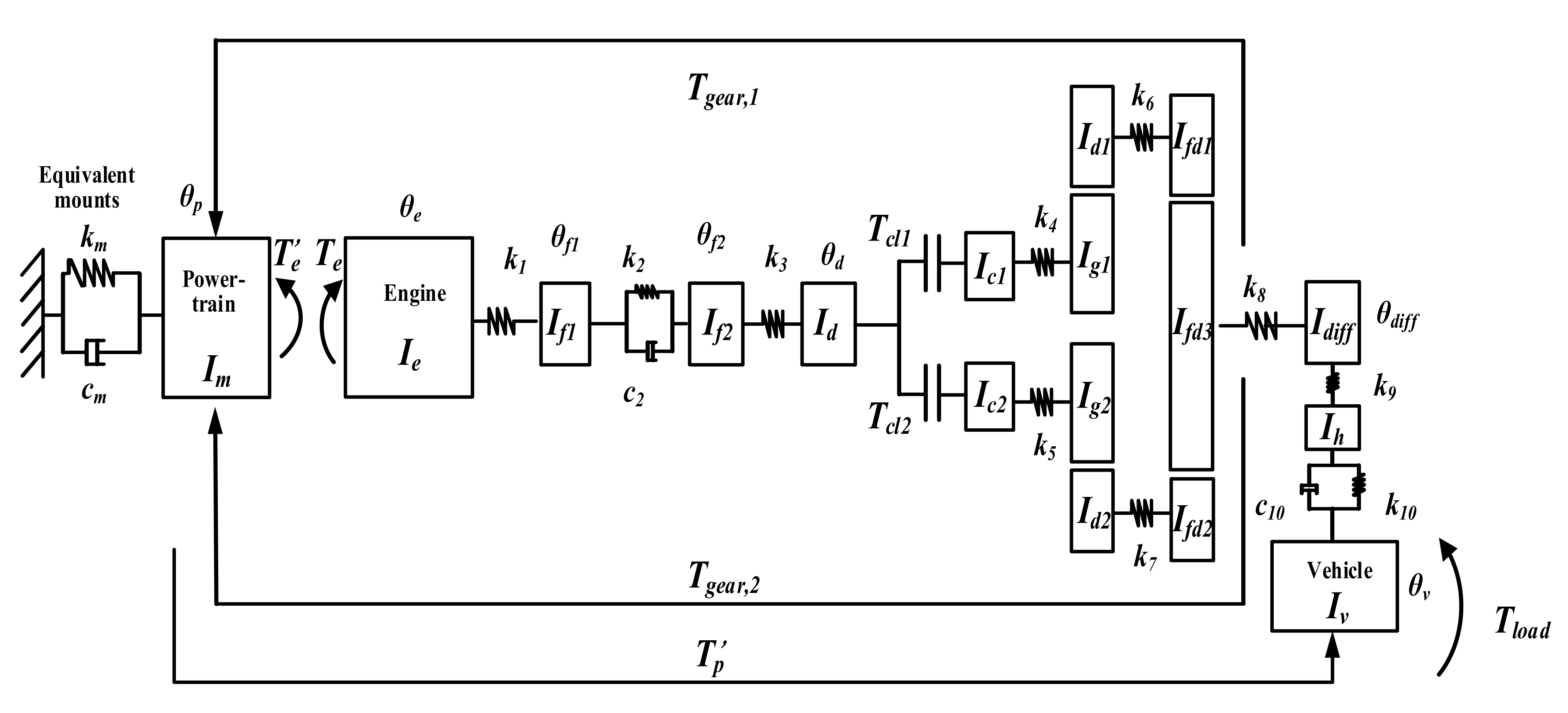
2. Dynamic Model of DCT Vehicle with Mount

2.1. Engine Torque Model

In the existing vehicle powertrain transmission system models, the engine mainly adopts a simplistic (average) model. The engine output torque is determined by throttle opening and speed of the engine from the table (ignoring the influence of the dynamic torque in the working process of the engine). According to references [19], this study establishes the engine dynamic torque model, which can more accurately reflect the output torque change of the engine in the actual working process. The established engine dynamic torque model is shown in Equation (1):
T e = T e m + T e m A n sin ( n θ + ϕ n ) + T r e c i ,
where Tem is the engine torque considering the engine intake, combustion and the torque calculated by the engine average model; A n sin ( n θ + ϕ n ) is the sum of the torque harmonic components with different amplitude, frequency and initial phase related to engine torque; Treci is the reciprocating inertia of the piston motion.

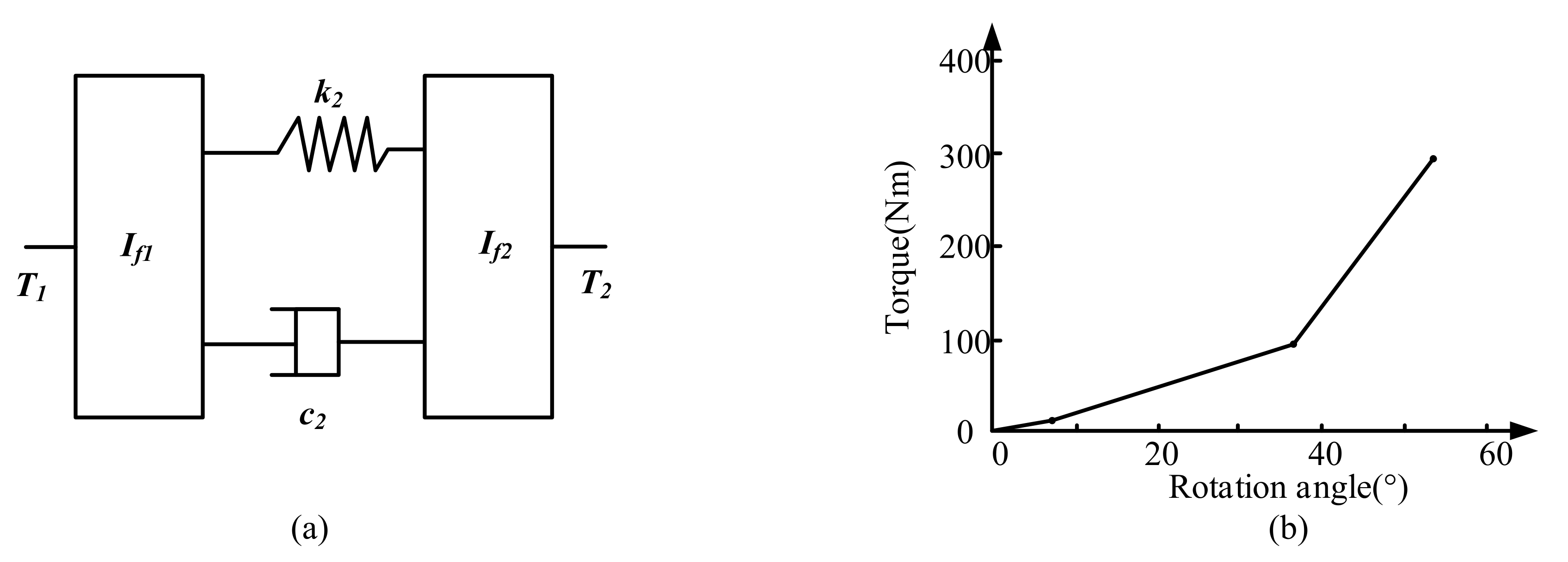
2.2. Dual Mass Flywheel Model

The dynamic model of the dual mass flywheel (DMF) is established using the lumped parameter method [20], as shown in Figure 1a. The dynamic equation are as follows:
I f 1 θ ¨ f 1 = T 1 k 2 θ f 1 θ f 2 c 2 θ ˙ f 1 θ ˙ f 2 ,
I f 2 θ ¨ f 2 = k 2 θ f 1 θ f 2 + c 2 θ ˙ f 1 θ ˙ f 2 T 2 ,
where If1 and If2 are the inertia of the first and second masses of the DMF respectively; θf1 and θf2 are torsion angles of the first and second masses; T1 is the driving torque acting on the first mass; T2 is the torque acting on the second mass; k2 is the spring stiffness between the first and second masses and c2 is the spring damping between the first and second masses.
In order to make the DMF have an ideal damping performance during various working conditions, Figure 1b shows the spring stiffness K2 between the first and second masses.

2.3. Clutch Model

The clutch has three working states: fully disengaged, sliding and engaged. According to the working state of the clutch, the linearly simplified Stribeck friction model is adopted to acquire the expression [21], that is:
T c = 0   clutch   disengaged   N μ k F n R   clutch   slipping T l o c k   clutch   engaged ,
R = 2 ( R 2 3 R 1 3 ) 3 ( R 2 2 R 1 2 ) ,
T l o c k = I c 1 T 3 + I d k 4 ( θ c 1 θ g 1 ) I d + I c 1 ,
where Tc is the clutch torque; μ k is the sliding friction coefficient; N is the number of clutch friction surfaces; Fn is the pressing force acting on the clutch; R is the equivalent action radius of the friction plate; R1 is the inner diameter of the friction plate; R2 is the outer diameter of the friction plate and Tlock is the torque transmitted after full engagement.

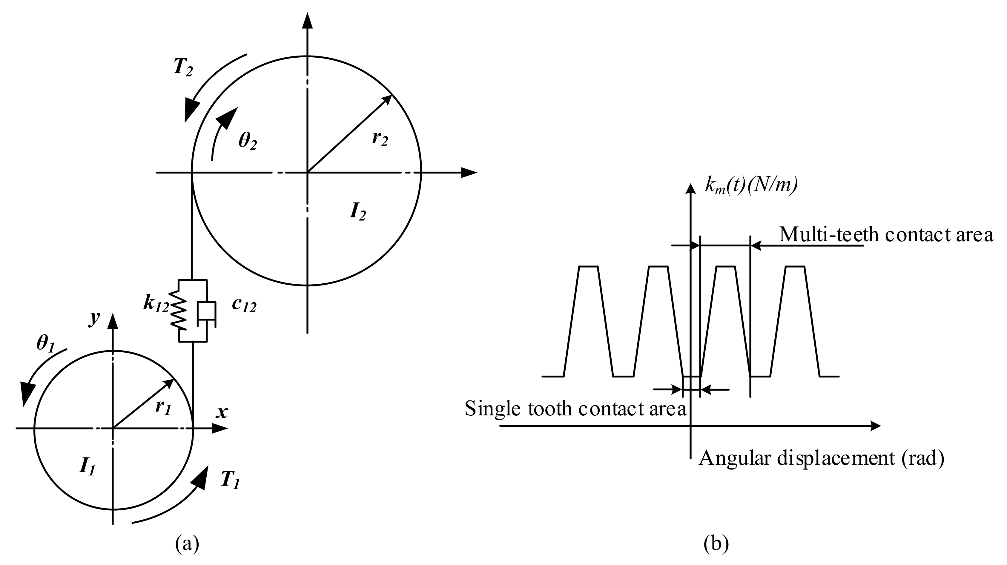
2.4. Gear System Model

The torsional dynamic model of a pair of gears is shown in Figure 2a. The dynamic model of a DCT gear system was established by the lumped parameter method [22,23,24], and the equations are as follows:
I 1 θ ¨ 1 + c 12 r 1 ( r 1 θ ˙ 1 r 2 θ ˙ 2 ) + k 12 r 1 ( r 1 θ 1 r 2 θ 2 ) = T 1 ,
I 2 θ ¨ 2 + c 12 r 2 ( r 2 θ ˙ 2 r 1 θ ˙ 1 ) + k 12 r 2 ( r 2 θ 2 r 1 θ 1 ) = T 2 ,
where Ii i(i = 1, 2) is the inertia of gear 1 and gear 2; θi i(i = 1, 2) is the torsion angle of gear 1 and gear 2; ri i(i = 1, 2) is the base circle radius of gear 1 and gear 2; k12 and c12 are the time-varying meshing stiffness and meshing damping of the gear pair, and Ti i(i = 1, 2) is the torque acting on gear 1 and gear 2.
During gear pair meshing, the meshing stiffness changes due to the alternating of the single and double tooth meshing, as shown in Figure 2b. The time-varying meshing stiffness is fitted as a function with a constant period change of the gear rotation angle by the Fourier series method [25,26] as follows:
k 12 ( θ 1 ) = k ¯ 12 + l = 1 a l cos [ l ( Z 1 θ 1 + γ 12 ) ] ,
where k ¯ 12 is the average value of the meshing stiffness within a meshing period; al is the Fourier expansion coefficient; l is the number of harmonics; Z1 is the number of teeth of gear 1; γ12 is the initial phase of the meshing stiffness; ks is the meshing stiffness of a single tooth region and εα is the contact ratio.

2.5. Vehicle Dynamic Model with Mount

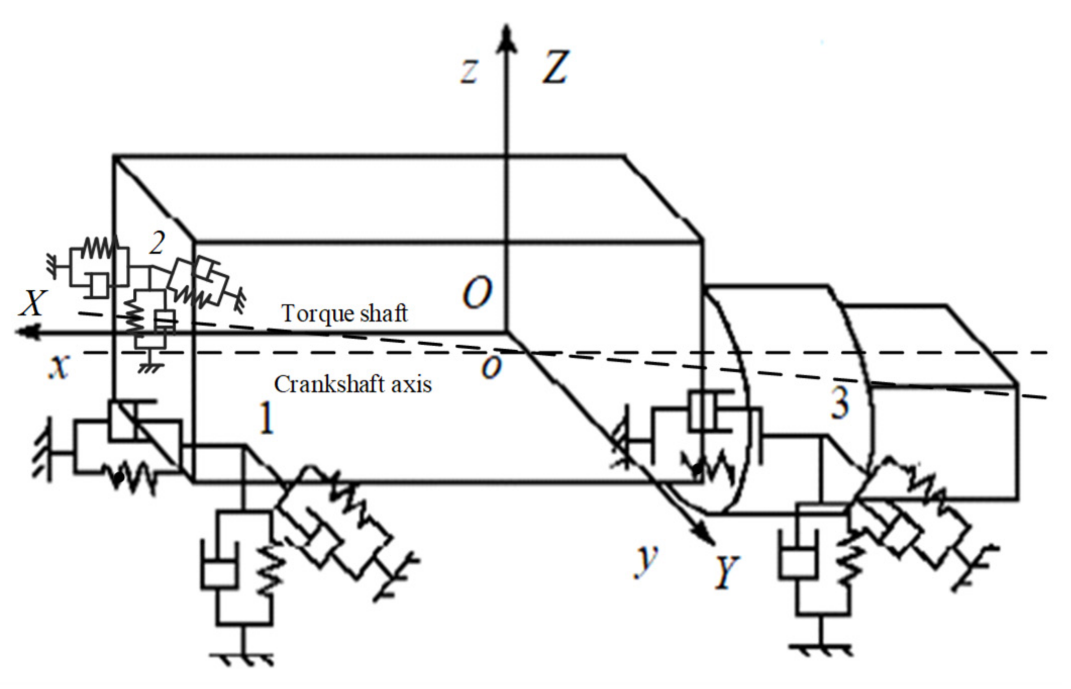
2.5.1. Powertrain Mounting System Model

In this paper, the powertrain mounting system is a three-point mount, and the engine is placed longitudinally. A coupling dynamic model of vehicle considering mount was established [27,28,29]. Considering the translational and torsional motion of the powertrain in the three axis directions, the powertrain mounting system is simplified into a 6-DOF dynamic model, as shown in Figure 3.
In Figure 3, O-XYZ is the moving coordinate system; O is the center of mass of the powertrain; X is the forward direction of the vehicle; Y is determined by the right-hand rule and Z is the vertical direction of the vehicle. The coordinate system o-xyz is a static coordinate system and the origin coincides with the center of mass of the powertrain. 1, 2 and 3 are the three mounting points on the powertrain. q (X Y Z θX θY θZ)T represents the generalized coordinates of powertrain mounting system.
Using the Lagrange method, the motion equation of the powertrain mounting system is established as follows:
d d t E T q ˙ E T q ˙ + E V q + E D q ˙ = F ,
where ET is the kinetic energy of the system; ED is the dissipated energy of the system; EV is the potential energy of the system and F is the generalized force of the system.
The kinetic energy of the powertrain includes translational kinetic energy and rotational kinetic energy as follows:
E T = 1 2 X ˙ Y ˙ Z ˙ θ ˙ X   θ ˙ Y   θ ˙ Z m p 0 0 0 0 0 0 m p 0 0 0 0 0 0 m p 0 0 0 0 0 0 I m , x x I m , x y I m , xz 0 0 0 I m , y x I m , y y I m , y z 0 0 0 I m , z x I m , z y I m , z z X ˙ Y ˙ Z ˙ θ ˙ X θ ˙ Y θ ˙ Z = 1 2 q ˙ T M q ˙ ,
and the mass matrix M is:
M = m p 0 0 0 0 0 0 m p 0 0 0 0 0 0 m p 0 0 0 0 0 0 I m , xx I m , xy I m , xz 0 0 0 I m , yx I m , yy I m , yz 0 0 0 I m , zx I m , zy I m , zz ,
The system potential energy of the powertrain is:
E V = 1 2 i = 1 n Δ u i   Δ v i   Δ w i k ui 0 0 0 k vi 0 0 0 k wi Δ u i Δ v i Δ w i = 1 2 q T Kq , K i = k ui 0 0 0 k vi 0 0 0 k wi .
The system dissipated energy of the powertrain is:
E D = 1 2 i = 1 n Δ u ˙ i   Δ v ˙ i   Δ w ˙ i c ui 0 0 0 c vi 0 0 0 c wi Δ u ˙ i Δ v ˙ i Δ w ˙ i = 1 2 q ˙ T C q ˙ , C i = c ui 0 0 0 c vi 0 0 0 c wi .
The excitation force received by the powertrain mounting system is:
[ F ] = F x   F y   F z   M x   M y   M z ,
where
F x = F mou , F y = 4 m 2 r λ w e 2 sin θ cos 2 w e t , F z = 4 m 2 r λ w e 2 cos θ cos 2 w e t , M x = T e ( 1 + 1 . 3 sin 2 w e t ) , M y = F z A T e , M z = F y A ,
where 4 is the number of cylinders of the engine; m2 is the mass of reciprocating parts and a single-cylinder piston; θ is the setting position of the powertrain; r is the radius of the crank; λ is the ratio of the connecting rod length and radius of the crank; ωe is the angular velocity of the crankshaft; A is the horizontal length from the centerline of the second and third cylinders to the center of the mass of the powertrain and Te is the engine output torque.

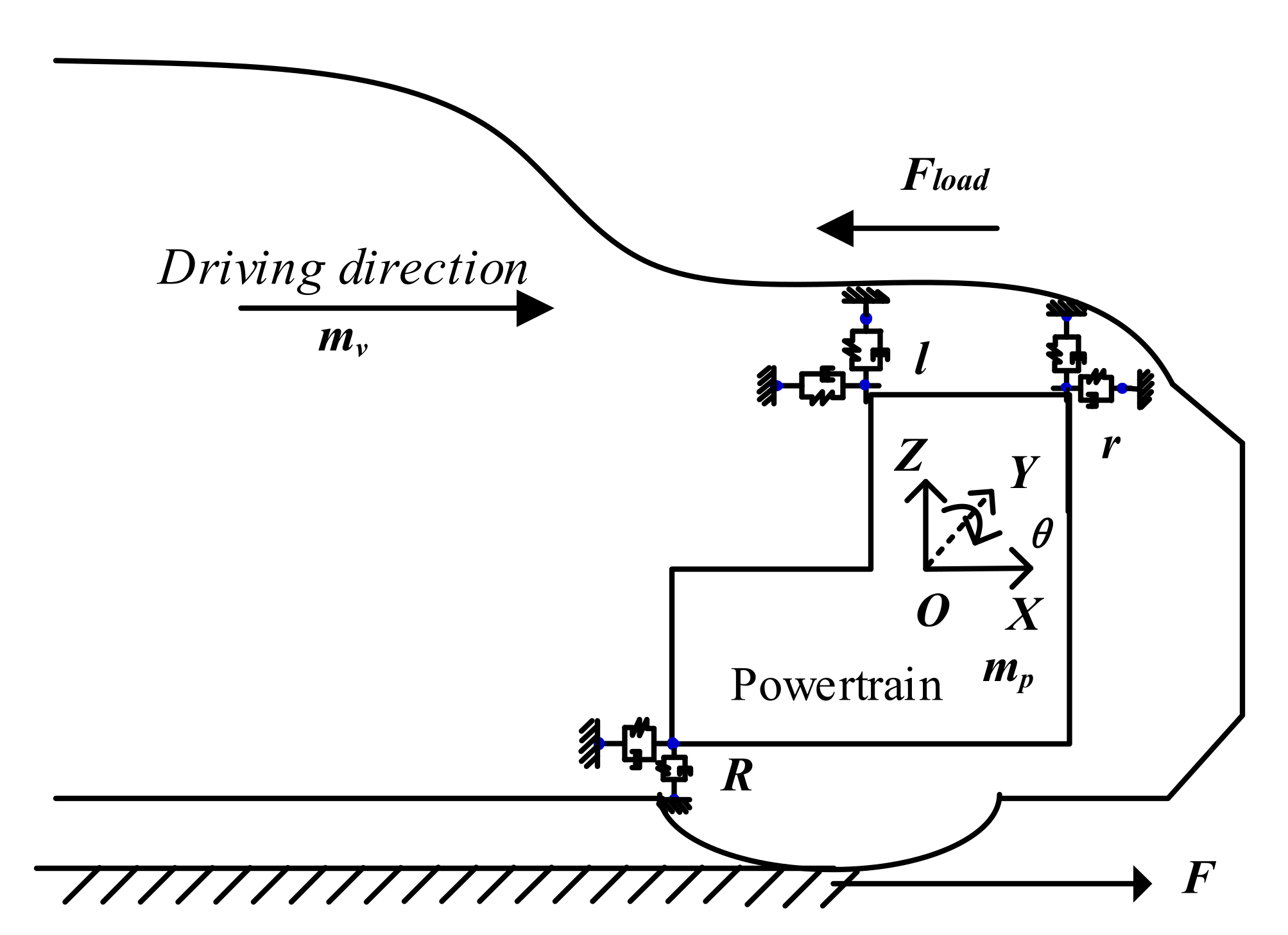
2.5.2. The Interaction between the Vehicle and the Powertrain

Considering the coupling relationship between the vehicle and the powertrain through the mount, is reflected as follows [29,30]:
(1) The vehicle and powertrain is a flexible connection on the mount. This study focuses on the influence of the mount on X, Z and the effect of torsion θY about the Y-axis. The interaction between the vehicle and powertrain is shown in Figure 4.
The dynamic equations of the interaction between the vehicle and powertrain are expressed as follows:
m p a p , x = F m o u m v a v , x = F F l o a d F m o u F m o u = F R x + F r x + F l x ,
where ap,x is the longitudinal acceleration of the powertrain; av,x is the longitudinal acceleration of the vehicle without the powertrain; Fix (i = r, l, R) is the longitudinal force of each mount.
(2) The relationship between the torque produced by the engine and the torque received by the powertrain and the torque transmitted by the vehicle driveline is shown in Figure 5. The reaction torque TP received by the powertrain can be expressed as:
Tp = Te + Tcl1(i1 − 1) + Tcl2(i2 − 1),
where Te is the reaction torque of engine; Tcl1 is the torque transmitted of clutch 1; Tcl2 is the torques transmitted of clutch 2; i1 is the transmission ratios of the power transmission paths of clutch 1; i2 is the transmission ratios of the power transmission paths of clutch 2.

2.5.3. Vehicle Dynamic Model with Mount

A 7-gear DCT vehicle is taken as the research object, and the lumped parameter method is used to develop the vehicle dynamic model with the powertrain mount, as shown in Figure 5. To simplify the illustration, the powertrain mount is represented as single-DOF stiffness-damping. However, it is considered as a 6-DOF model in the actual calculation, as shown in Figure 3. See Abbreviations for the definition of the symbols in the aforementioned formulas.
According to the established torsional dynamics model of the vehicle system, the equations are as follows:
I e θ ¨ e = T e k l θ e θ f l ,
I fl θ ¨ f 1 = k 1 θ e θ fl k 2 θ f 1 θ f 2 c 2 θ ˙ fl θ ˙ f 2 ,
I f 2 θ ¨ f 2 = k 2 θ f 1 θ f 2 + c 2 θ ˙ f 1 θ ˙ f 2 k 3 θ f 2 θ d ,
I d θ ¨ d = k 3 θ f 2 θ d T cl 1 T cl 2 ,
I cl θ ¨ cl = T cll k 4 θ cl θ g 1 ,
I g 1 θ ¨ g 1 = k 4 θ c 1 θ g 1 r g 1 F 11 ,
I d 1 θ ¨ d 1 = r d 1 F 11 k 6 θ d 1 θ fd 1 ,
I fd 1 θ ¨ fd 1 = k 6 θ d 1 θ fd 1 r fd 1 F 21 ,
I c 2 θ ¨ c 2 = T cl 2 k 5 θ c 2 θ g 2 ,
I g 2 θ ¨ g 2 = k 5 θ c 2 θ g 2 r g 2 F 12 ,
I d 2 θ ¨ d 2 = r d 2 F 12 k 7 θ d 2 θ fd 2 ,
I fd 2 θ ¨ fd 2 = k 7 θ d 2 θ fd 2 r fd 2 F 22 ,
I fd 3 θ ¨ fd 3 = r fd 3 F 21 + r fd 3 F 22 k 8 θ fd 3 θ diff ,
I diff θ ¨ diff = k 8 θ f d 3 θ diff k 9 θ diff θ h ,
I h θ ¨ h = k 9 θ diff θ h k 10 θ h θ v c 10   θ   ˙ h   θ   ˙ v ,
I v θ ¨ v = k 10 θ h θ v + c 10 θ ˙ h θ ˙ v T load + r w C 11 X ˙ p r w θ ˙ V + K 11 X p r w θ V + C 13 θ ˙ p + K 13 θ p .
Considering the 6-DOF vibration equation of the powertrain mounting system along the vehicle’s forward direction, the vertical and lateral translation and torsion are as follows:
m p X ¨ P = F mou C 13 θ ˙ p K 13 θ p ,
m p Y ¨ P = C 11 Y ˙ p K 11 Y p + m 1 r w 2 a 1 sin ( wt + φ 1 ) ,
m p Z ¨ P = C 22 Z ˙ p K 22 Z p C 23 θ ˙ p K 23 θ p + ( m 1 + m 2 ) r w 2 a 1 cos ( wt + φ 1 ) α + m 2 r w 2 λ a 2 cos ( 2 wt + φ 11 ) ,
I m , xx θ xp = C 33 θ ˙ xp K 33 θ xp C 13 ( X ˙ p r θ ˙ V ) K 13 ( X p r θ V ) C 23 Z ˙ p K 23 Z p + T e ( 1 + 1.3 sin ( 2 w e t ) ) T c 1 T c 2 ,
I m , yy θ yp = C 33 θ ˙ yp K 33 θ yp C 13 ( X ˙ p r θ ˙ V ) K 13 ( X p r θ V ) C 23 Z ˙ p K 23 Z p + F z A ,
I m , zz θ zp = C 33 θ ˙ zp K 33 θ zp C 13 ( X ˙ p r θ ˙ V ) K 13 ( X p r θ V ) C 23 Z ˙ p K 23 Z p + F y A ,
The meshing force equation of the DCT gear system are as follows:
F 11 = k m 11 r g 1 θ g 1 r d 1 θ d 1 + c m 11 r g 1 θ ˙ g 1 r d 1 θ ˙ d 1 ,
F 12 = k m 12 r g 2 θ g 2 r d 2 θ d 2 + c m 12 r g 2 θ ˙ g 2 r d 2 θ ˙ d 2 ,
F 21 = k m 21 r fd 1 θ fd 1 r fd 3 θ fd 3 + c m 21 r fd 1 θ ˙ fd 1 r fd 3 θ ˙ fd 3 ,
F 22 = k m 22 r fd 2 θ fd 2 r fd 3 θ fd 3 + c m 22 r fd 2 θ ˙ fd 2 r fd 3 θ ˙ fd 3 ,

3. Simulation Results Considering Typical Working Conditions with Mount

The Matlab/Simulink software and the Runge–Kutta solver are employed to evaluate the effect of the mount on the longitudinal dynamic performance with a fixed step size of 10−6 during starting, shifting and tip-in/tip-out typical working conditions with parameters given by the vehicle enterprise (see Appendix A).
In this study, to more accurately reflect the influence of the mount on vehicle dynamic performance, vehicles with and without mounts are considered when establishing the vehicle dynamics model (without mount means that only the dynamic torque of the engine, nonlinear characteristics of the dual-mass flywheel, and time-varying meshing stiffness of the DCT gear system are considered; the influence of the mount is ignored. With mount means that the dynamic torque of the engine, nonlinear characteristics of the dual-mass flywheel, time-varying meshing stiffness of the DCT gear system, and six degrees of freedom powertrain mount model are considered.). The above two models are compared and analyzed under the same simulation conditions. Of course, in practice, there is no situation without a mount; therefore, the simulation results of the two vehicle dynamics models established are compared with the vehicle test results, and it is concluded that the vehicle dynamics model with a mount, established in this paper, can better reflect the influence of the mount on the longitudinal dynamic performance of the vehicle.

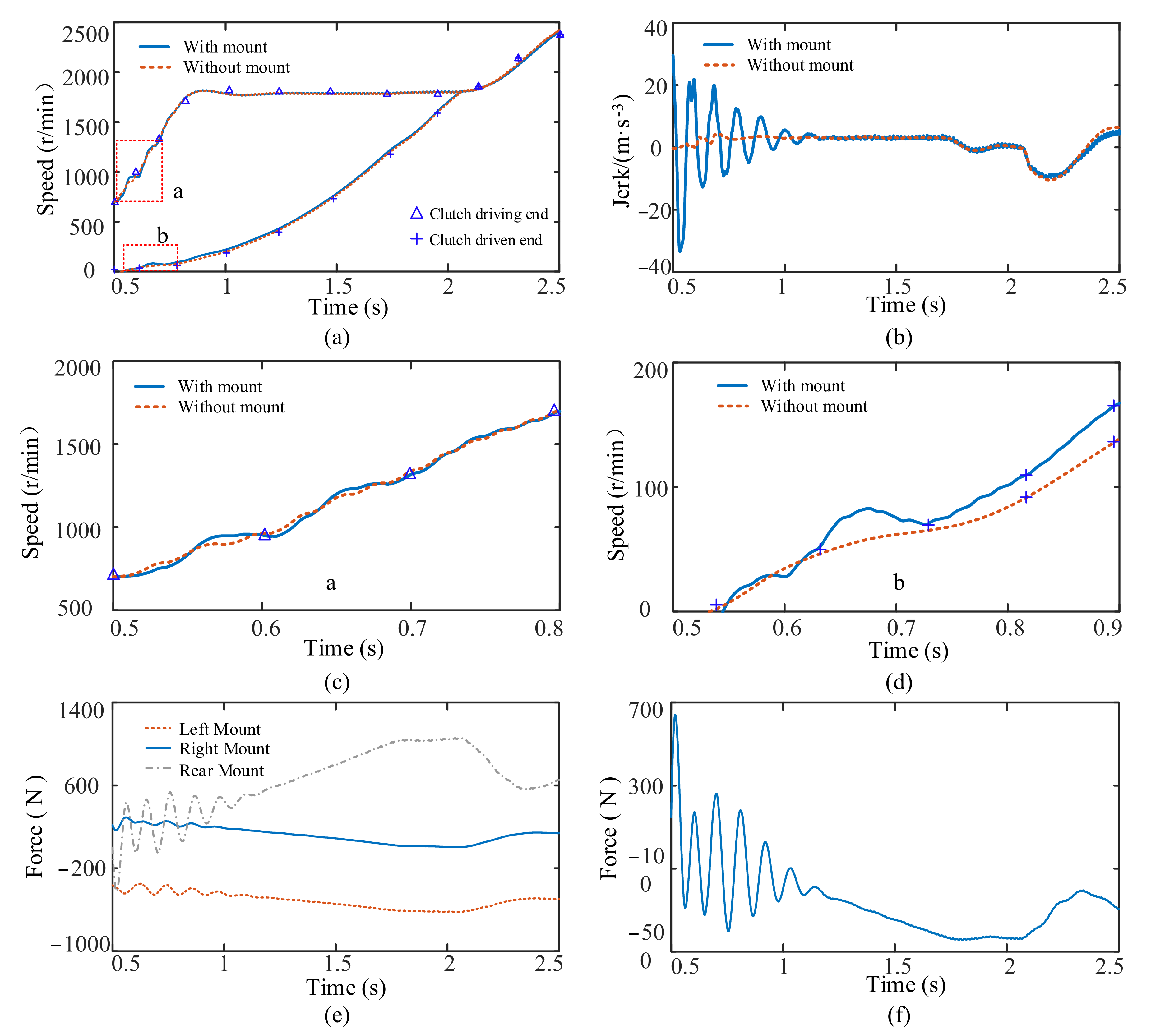
3.1. Starting Condition

The proportional integral differential control is adopted. The engine starts at a constant speed. Starting at 0.5 s, the engine speed gradually increases from an idle speed to 1800 r/min, which is maintained. The speeds of the clutch-driving plate and clutch 1 driven plate are synchronized at approximately 2 s, and the staring process is completed. The simulation results of the vehicle with and without the mount during the starting process are presented in Figure 6.
The overall trend of the speeds of the driving and driven ends of the clutch is the same with and without the mount, as shown in Figure 6a. However, at the beginning of the starting process, fluctuations in speeds with the mount are observed. For the starting process, the fluctuation in the speed of the driving and driven ends of the clutch gradually decreases (Figure 6c,d). The jerk of the vehicle, depicted in Figure 6b, reveals that when the mount is considered, the engine speed fluctuation causes the vehicle’s jerk to fluctuate with a large amplitude during the starting process and then gradually decreases and becomes stable. The maximum fluctuation amplitude of the jerk increases from 4 m/s−3 without the mount to 54 m/s−3 with the mount. When the starting process is being completed, the jerk of the vehicle also has a fluctuation due to the inconsistent acceleration of the driving and driven plates of the clutch. At the beginning of the starting process, the torque produced by the engine crankshaft torsion directly acts on the powertrain, and the longitudinal forces on the left, right, and rear mounts of the powertrain fluctuate, causing deformation of the mounts. For the starting process, the longitudinal force on the left and right mounts tends to be stable. As the vehicle accelerates, the longitudinal force on the rear mount increases. When the starting process is completed, the vehicle acceleration decreases and fluctuates. Therefore, the longitudinal force acting on the rear mount decreases and fluctuates, as displayed in Figure 6e. Figure 6f shows that the longitudinal force exerted by a powertrain on a vehicle through the mount fluctuates at the beginning of the starting process. With an increase in the force acting on the vehicle during starting, the force acting on the vehicle decreases significantly after starting. In summary, at the beginning of the starting process, the mount causes large fluctuations in the vehicle jerk.

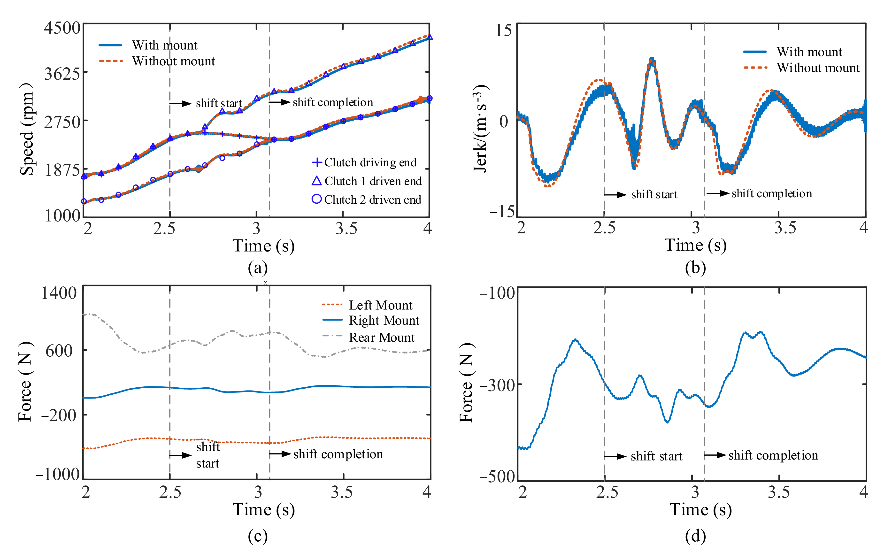
3.2. Shifting Condition

Here, the shifting from first to second gear is analyzed. The shifting begins at 2.5 s and completes at 3.1 s. The simulation results of the vehicle shifting process with and without the mount are from Figure 7.
The speed changes of driving end of clutch, the driven end of clutch 1 and driven end of clutch 2 (during the shifting process and the overall trend of the speed changes of the clutch driving end and driven end) are the same when with and when without the mount from Figure 7a. The change of jerk during the shifting process is seen in Figure 7b. At the beginning of shifting, the fluctuation amplitude of the jerk with the mount is bigger than that without the mount. The maximum fluctuation amplitude of the jerk increases from 16.3 m/s−3 without the mount to 17.2 m/s−3 with the mount. After shifting is completed, the fluctuation amplitude of the jerk reduces slowly with the mount. The maximum fluctuation amplitude of the jerk decreases from 13 m/s−3 without the mount to 12.8 m/s−3 with the mount. Simultaneously, because the engine adopts the dynamic torque model, the output torque of the engine fluctuates, which can act on the vehicle through the mount. Therefore, when the mount is considered, there is an obvious high frequency fluctuation in the jerk of the vehicle. The longitudinal force acting on the right and left mounts is unchanged during shifting, whereas the longitudinal force acting on the rear mount fluctuates in Figure 7c. The force of the powertrain acting on the vehicle through the mount fluctuates during shifting from Figure 7d.

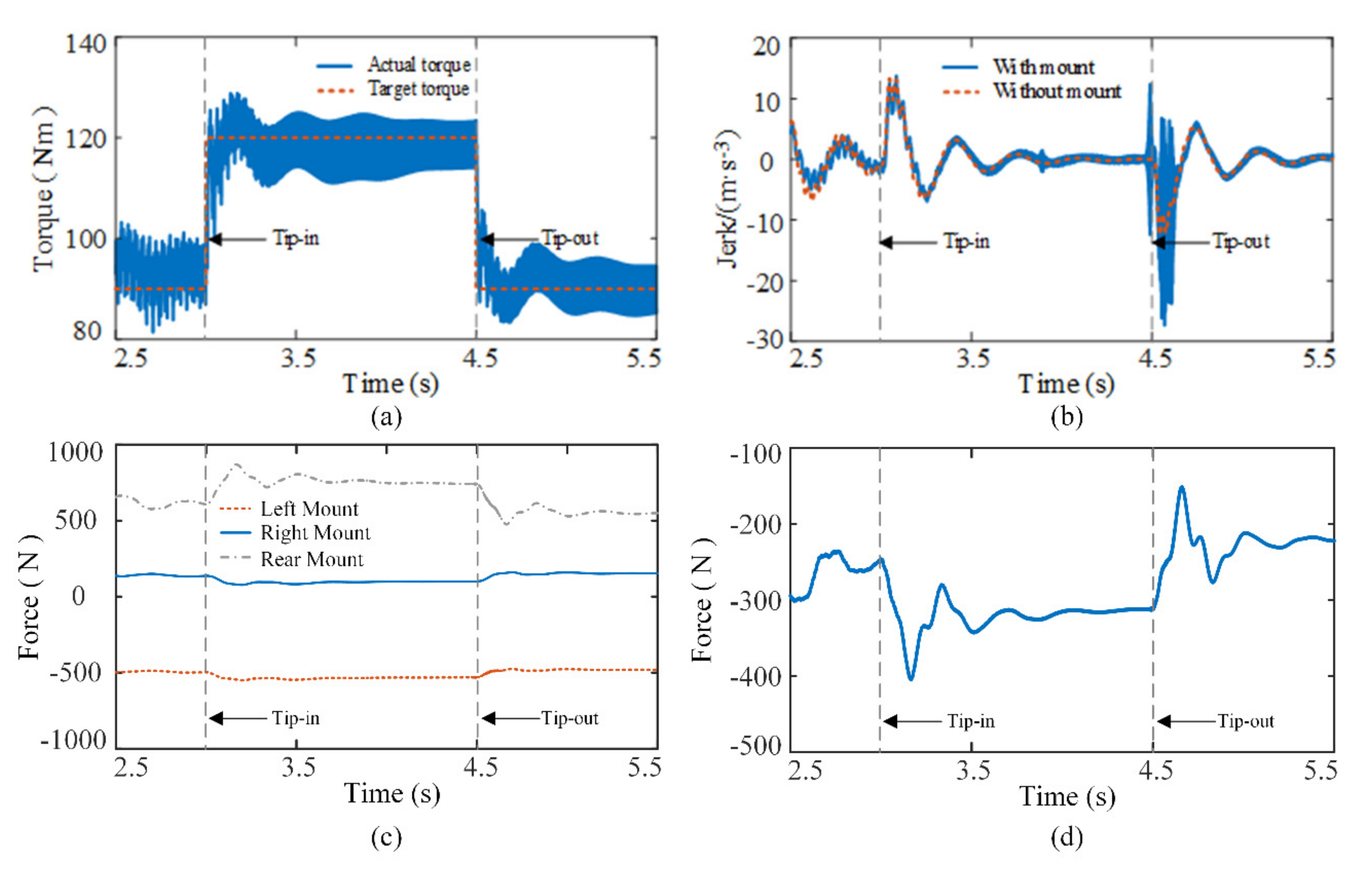
3.3. Tip-In/Tip-Out Condition

The simulation is initiated with the vehicle running stable in the second gear. The step change of the engine output torque is used to simulate the tip-in/tip-out condition at 3 s and 4.5 s from Figure 8a. The simulation results of the vehicle in the tip-in and tip-out conditions with and without the mount are shown in Figure 8.
Due to the sudden change of the vehicle driveline torque under the tip-in and tip-out conditions, the jerk of the vehicle with and without the mount has a large fluctuation from Figure 8b. Under the tip-in condition, the vehicle jerk with and without the mount are close. Under the tip-out condition, the jerk of the vehicle with the mount has a greater amplitude fluctuation than that without the mount, the maximum fluctuation amplitude of the jerk increases from 17.6 m/s−3 without the mount to 34.1 m/s−3 with the mount, which affects the ride comfort of the vehicle. Simultaneously, because the engine adopts the dynamic torque model, the output torque of the engine fluctuates, which can act on the vehicle through the mount. Therefore, when the mount is considered, there is an obvious high frequency fluctuation in the jerk of the vehicle. It can be seen from Figure 8c that as a result of the sudden change of the system torque under tip-in and tip-out conditions, the longitudinal force acting on the mount changes. Meanwhile, the force of the powertrain acting on the vehicle through the mount increases significantly under the tip-in and tip-out conditions in Figure 8d.

4. Influence of Mount Parameters on the Longitudinal Dynamic Performance of the Vehicle

The dynamic model of the vehicle with the powertrain mount is used to analyze the impact of mount damping and stiffness on the dynamic characteristics of the vehicle. The parameter values of the mount are shown in Appendix A. Figure 9a,b show how the damping and stiffness of the mount are kept unchanged and the analysis of the effect of different stiffnesses and damping on the jerk during the starting process, respectively. Figure 9c,d show how the damping and stiffness of the mount are kept unchanged and the analysis of the effect of different stiffnesses and damping on the jerk during the shifting process, respectively.
Under the given parameter conditions, Figure 9a shows that the mount stiffness significantly impacts the amplitude and frequency of the fluctuation in the vehicle’s jerk at the beginning of the starting process. The greater the mount stiffness, the greater are the amplitude and the frequency of the fluctuation in the vehicle’s jerk. When the mount stiffness is one-third times, one times and three times the original amount, the maximum fluctuation amplitude of the jerk is 8.2 m/s−3, 54 m/s−3, and 113 m/s−3, respectively. Compared with one times the mount stiffness, the maximum fluctuation amplitude of the jerk at one-third times of the mount stiffness decreases by 84.8%, and the maximum fluctuation amplitude of the jerk increases by 109.3% at three times the mount stiffness. Figure 9b shows that the mount damping significantly impacts the fluctuation amplitude of the vehicle’s jerk during the vehicle’s starting process. At the beginning of the starting process, the smaller the mount damping, the greater is the fluctuation amplitude of the jerk. After starting, the mount damping slightly affects the change in the jerk. When the mount damping is one-third times, one times and three times the original amount, the maximum fluctuation amplitude of the jerk is 105 m/s−3, 54 m/s−3 and 11 m/s−3, respectively. Compared with one times the mount damping, the maximum fluctuation amplitude of the jerk at one-third times of the mount damping increases by 94.4%, and the maximum fluctuation amplitude of the jerk decreases by 79.6% at three times the mount damping. Figure 9c shows that the mount stiffness impacts the low-frequency fluctuation amplitude of the vehicle’s jerk during the shifting process. The greater the mount stiffness, the greater is the low-frequency fluctuation amplitude of the vehicle’s jerk. Moreover, the mount stiffness impacts the low-frequency fluctuation of the vehicle’s jerk. When the mount stiffness is one-third times, one times and three times, the maximum fluctuation amplitude of the jerk is 14 m/s−3, 14.9 m/s−3, and 15.4 m/s−3 respectively. Compared with one times of mount stiffness, the maximum fluctuation amplitude of the jerk at one-third times of mount stiffness decreases by 6%, and the maximum fluctuation amplitude of the jerk increases by 3.4% at three times the mount stiffness. Figure 9d shows that the mount damping impacts the high-frequency fluctuation amplitude of the vehicle’s jerk during the shifting process. The greater the mount damping, the greater is the high-frequency fluctuation amplitude of the jerk.

5. Test Results and Discussion

The starting test of a sport utility vehicle equipped with a 7-gear DCT was carried under different working conditions and with different throttle openings. The main parameters of the test vehicle are listed in Appendix A. The data acquisition equipment is VECTOR GL1000, which reads the vehicle driving data through the CAN bus. The maximum sampling frequency is 1 kHz. The test vehicle and data acquisition equipment are shown in Figure 10. The test route is about 100 km, with 20 groups of data, including urban central, congested, urban suburban, and mountain roads.
To verify the correctness and rationality of the established vehicle model, the results of the vehicle test and vehicle model with and without mount under the starting, shifting, and tip-in/tip-out conditions are compared, as shown in Figure 11.
Under the same starting, shifting, and tip-in/tip-out conditions, the overall trend of the clutch driving-end- and clutch driven-end speeds are basically consistent between the simulation, with and without the mount, and test processes, as shown in Figure 11a,c. From Figure 11b,d,f, the overall trend of jerking obtained from both the simulation and test is also consistent. However, in Figure 11b, which shows the jerking observed in the test, at the beginning of starting there is a high amplitude fluctuation of the jerk due to the influence of the mount. Compared with the simulation results, when the powertrain mount is used, its influence on the starting process is evident. In Figure 11d,f, because the fluctuation of the engine’s output torque is transmitted to the vehicle through the mount, the jerk of the vehicle has a high-frequency and low-amplitude fluctuation, and the larger the engine speed, the greater the fluctuation amplitude. Compared with the simulation results, when the powertrain mount is introduced, it can reflect the impact of the engine torque fluctuation on the jerk more effectively. In conclusion, the established vehicle dynamics simulation model with a mount is effective and viable. This established model can be used to analyze the longitudinal dynamics characteristics of DCT vehicles.

6. Conclusions

A vehicle dynamic model with a mount was established. The simulation and analysis of the effect of the mount on the longitudinal dynamic performance during starting, shifting, and tip-in/tip-out working conditions were performed, and the following conclusions were obtained.
(1)
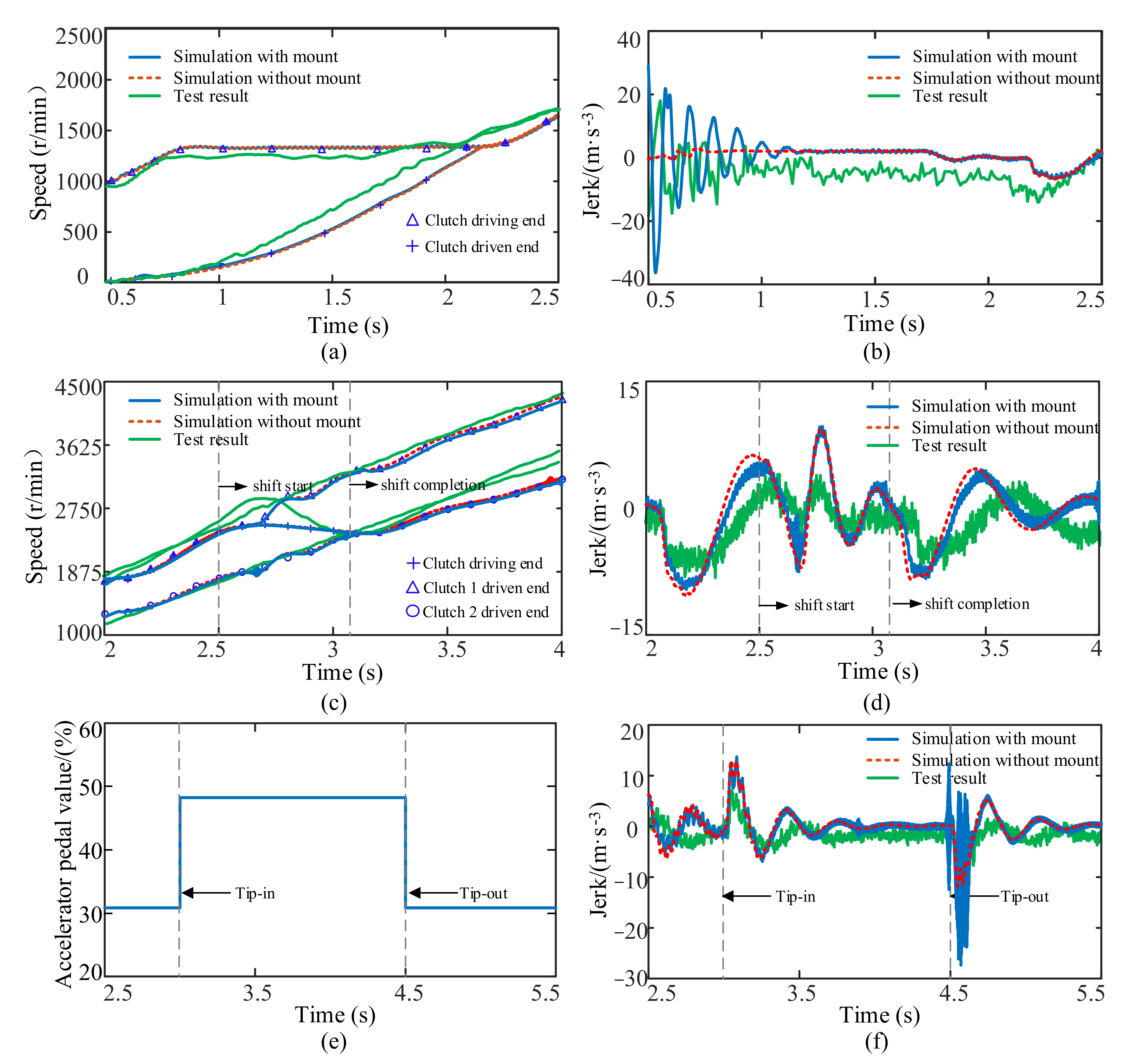
The powertrain mount significantly impacts the longitudinal dynamic performance of DCT vehicles during starting, shifting, and tip-in/tip-out processes. The bigger the torque change in the vehicle powertrain, the bigger is the influence of the mount on the vehicle. Additionally, the higher the engine speed, the more obvious the fluctuation amplitude. Simultaneously, the engine torque fluctuation is transmitted to the vehicle through the mount, which causes the jerk to produce high-frequency, low-amplitude fluctuations. The simulation results of the two vehicle dynamics models established are compared with the test results. It is concluded that ignoring the influence of the mount when building the vehicle model leads to a large error between the simulation results and the actual situation. Additionally, the established vehicle dynamics model with a mount can reflect the influence of the mount on the longitudinal dynamics performance of the vehicle better.
(2)
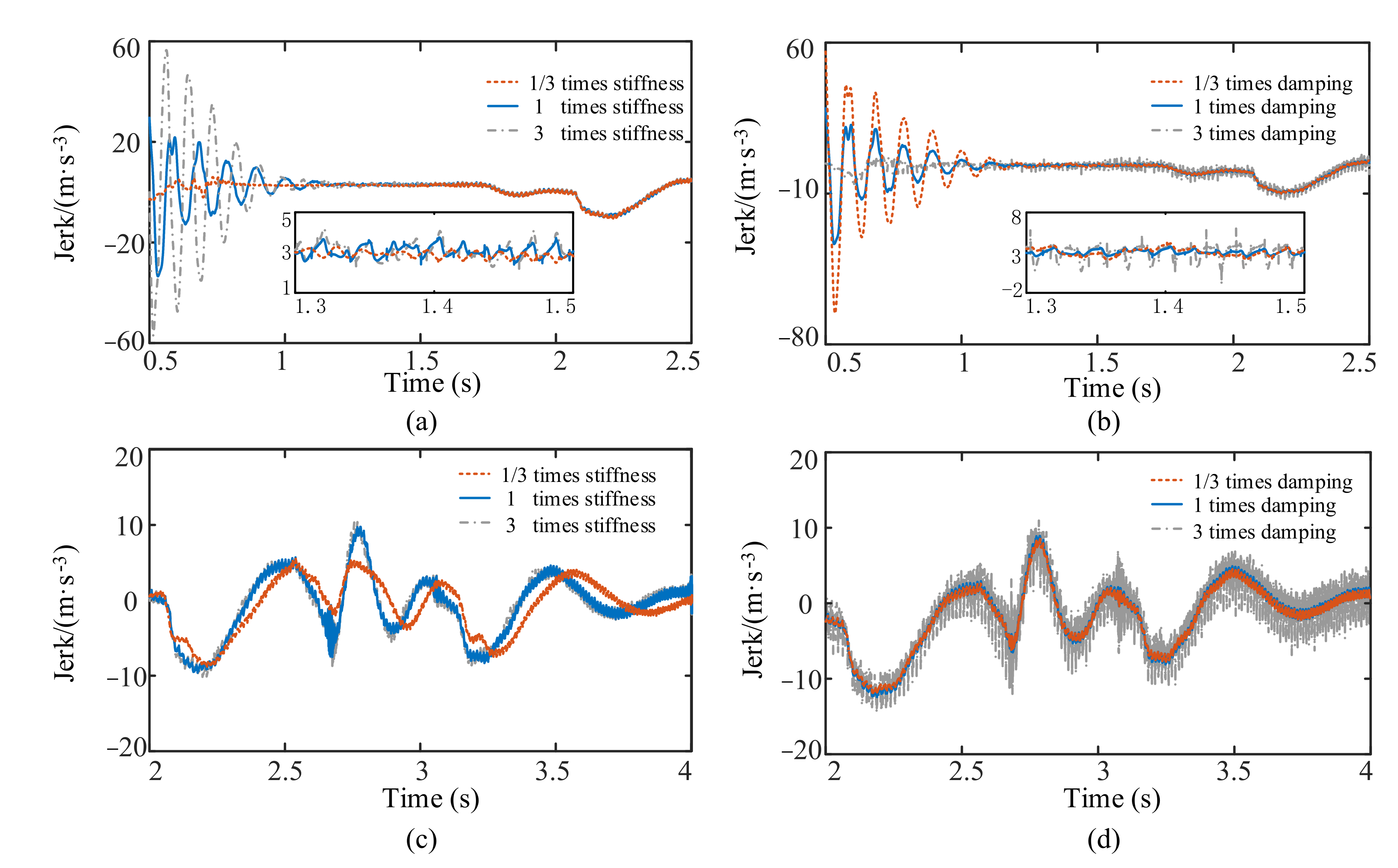
The powertrain mount’s stiffness affects the frequency and amplitude of the fluctuation in the vehicle’s jerk. The greater the mount stiffness, the greater are the fluctuation frequency of the jerk. The powertrain mount’s damping also significantly influences the fluctuation amplitude of the vehicle’s jerk. The greater the mount damping, the lower is the fluctuation amplitude of the jerk. The results provide a reference for the optimization of the powertrain mounting system.

Author Contributions

Methodology, formal analysis, validation, writing—original draft preparation, Z.G.; conceptualization, writing—review and editing, D.Q.; software, A.L. and J.F.; Provided vehicle data and test support, analyed the data and involved in writing the manuscript Y.L. All authors have read and agreed to the published version of the manuscript.

Funding

This research was funded by the National Natural Science Foundation of China, grant number U1764259.

Acknowledgments

The authors would like to thank engineer Qing Zhang of Chongqing Chang’an Automobile Co., Ltd., Chongqing, China, for providing data and experimental support.

Conflicts of Interest

The authors declare no conflict of interest.

Abbreviations

SymbolMeaning
av,xthe longitudinal acceleration of the vehicle (excluding Powertrain)
ap,xthe longitudinal acceleration of the powertrain
Cthe damping matrix
Cix(i = r, l, R)damping of each mount in X direction
Cizdamping of each mount in Z direction
Cpequivalent damping of the powertrain mount
c2torsional damping of the DMF
c10the torsional damping of the output shaft
Fthe driving force of the vehicle
Fix(i = r, l, R)the force transmitted by each mount in the longitudinal direction
Floadthe vehicle total drag force
Fmouthe total force transmitted by the mount
i1the transmission ratio of power along the transmission path of clutch 1
i2the transmission ratio of power along the transmission path of clutch 2
ia1the ratio of final drive 1
ia2the ratio of final drive 2
Ic,yythe inertia of powertrain in Y direction
Idthe equivalent moment of inertia of the driving plate of the clutch
Ivthe equivalent moment of inertia of the vehicle to the output shaft (including the powertrain mounting system)
Ivthe equivalent moment of inertia of the vehicle to the output shaft (not including the powertrain mounting system)
Iethe moment of inertia of the engine crankshaft
Ieqthe equivalent moment of inertia of the driven plate of clutch
I1moment of inertia of intermediate shaft 1 and final reduction drive 1
I2moment of inertia of intermediate shaft 2 and final reduction drive 2
Ihmoment of inertia of external input shaft
Kthe stiffness matrix
Kpequivalent stiffness of the powertrain mount
k2torsional stiffness of the DMF
k10the torsional stiffness of the output shaft
Kix(i = r, l, r)stiffness of each mount in X direction
Kizstiffness of each mount in Z direction
lleft mount
liz(i = r, l, R)the distance from each mount to the Z direction of the centroid
lix(i = r, l, R)the distance from each mount to the X direction of the centroid
Mthe mass matrix
mpthe mass of the powertrain
mvthe mass of the vehicle without powertrain
Othe center of mass of powertrain
qthe generalized coordinates
rthe right mount
rwthe wheel radius
Rrear mount
Xthe center of mass of the powertrain in the longitudinal direction
Xvthe longitudinal displacement of the vehicle
X ˙ v the longitudinal speed of the vehicle
Xthe longitudinal displacement of the powertrain
X ˙ the longitudinal speed of the powertrain
Zthe center of mass of powertrain in vertical direction
Ythe center of mass of the powertrain in the transverse direction
θthe angular displacement of the powertrain
Tpthe total reaction torque
Tethe torque of the engine
Tethe reaction torque caused by the engine
Tgear,i (i = 1, 2)the reaction torque caused by the torque transmitted through clutch 1 or clutch 2
TB,jthe friction torque of bearing
Tintransmission input torque
Touttransmission output torque
Tc1transmission torque of clutch 1
Tc2transmission torque of clutch 2
Tloadthe load torque
τthe transmission speed ratio
θpthe angular displacement of the powertrain
θEthe angular displacement of engine
θDthe angular displacement of the driving plate of the clutch
θTthe angular displacement of the output shaft
θVthe angular displacement of vehicle

Appendix A

Table A1. Powertrain model parameters.
ParametersValueParametersValue (kg·m2)ParametersValue (Nm/rad)
mv1620 kgIe0.03k195,000
mp253kgIf1/If20.075k2200
rw0.35 mId0.01k3200,000
CD0.328Ic10.0072k4200,000
A2.12 m2Ic20.0125k5870,000
i14.214Ig10.0006k6560,000
i23.105Ig20.0013k7470,000
i31.724Ip10.005k8165,000
i41.268Ip20.005k9165,000
i51.27Ifd10.0028k1040,000
i61.049Ifd20.16ParametersValue (Nms/rad)
i70.891Ifd30.0009c20.01
iR3.227Idiff0.16c104
ia13.944Ih0.6992--
ia23.227Iv202.45--
Table A2. Powertrain mounting system parameters.
Mount Inertia ParametersValue (kg·m2)
Im,xx16.712
Im,yy7.717
Im,zz14.829
Im,xy−1.026
Im,yz3.209
Im,zx−1.482
Mount NameMount Static Stiffness (N/mm)
xyz
left mount130530400
right mount150150180
rear mount1901010
Table A3. The innovation of this paper and its comparison with existing important literature.
LiteratureModeling MethodComparison of Results and Findings
Reference [7]The dynamic model of the DCT vehicle’s starting process was established without considering the influence of powertrain mount.Because the influence of mounting is not considered, the fluctuation of the longitudinal acceleration of the vehicle caused by the deformation of the mounting during the starting process of the vehicle is underestimated.
Reference [17]A dynamic model of vehicle with three degree of freedom powertrain mount was established. The nonlinear characteristics of dual mass flywheel and time-varying meshing stiffness of transmission gear system are not considered.The influence of engine torque fluctuation and time-varying meshing stiffness on the mount is ignored, and the influence of the mount on the vehicle performance in the actual vehicle is not accurately reflected.
The method proposed in this paperThe vehicle dynamic model not only considers the dynamic torque of the engine, nonlinear characteristics of the dual-mass flywheel, and time-varying meshing stiffness of the DCT gear system, but also considers the vehicle coupling dynamics model of the powertrain mount with six degrees of freedom.The powertrain mount has an impact on the fluctuation frequency and amplitude of the DCT-vehicle impact. When the torque of the vehicle transmission system changes greatly, such as under starting and tip in/tip out conditions, the mount has a greater impact on the dynamic performance of the vehicle. The DCT coupling dynamic model can reflect the influence of the actual vehicle mount on the vehicle performance better.

References

  1. Fan, R.L.; Chen, J.A.; Zhang, C.Y.; Fei, Z.N.; Wang, P.; Wu, Q.F. Linearisation modelling and active performance simulation of active engine mounts with an oscillating coil actuator for automotive powertrain. Int. J. Veh. Des. 2022, 85, 178–196. [Google Scholar] [CrossRef]
  2. Walker, P.D.; Zhang, N. Modelling of dual clutch transmission equipped powertrains for shift transient simulations. Mech. Mach. Theory 2013, 60, 47–59. [Google Scholar] [CrossRef]
  3. Walker, P.D.; Zhang, N. Numerical investigations into shift transients of a dual clutch transmission equipped powertrains with multiple nonlinearities. J. Vib. Control 2013, 21, 1473–1486. [Google Scholar] [CrossRef]
  4. Chen, L.; Shi, W.; Chen, Z. Research on Damping Performance of Dual Mass Flywheel Based on Vehicle Transmission System Modeling and Multi-Condition Simulation. IEEE Access 2020, 8, 28064–28077. [Google Scholar] [CrossRef]
  5. Bai, J.; Wu, X.; Gao, F.; Li, H. Analysis of Powertrain Loading Dynamic Characteristics and the Effects on Fatigue Damage. Appl. Sci. 2017, 7, 1027. [Google Scholar] [CrossRef] [Green Version]
  6. Galvagno, E.; Velardocchia, M.; Vigliani, A. Dynamic and kinematic model of a dual clutch transmission. Mech. Mach. Theory 2011, 46, 794–805. [Google Scholar] [CrossRef] [Green Version]
  7. Yang, Y.; Wang, M.; Xia, F.; Qin, D.; Feng, J. Modeling and Control Approach for Dual Clutch Transmission Vehicles Starting Process Based on State-Dependent Autoregressive with Exogenous Model. IEEE Access 2020, 8, 158712–158726. [Google Scholar] [CrossRef]
  8. Wang, X.W.; Lu, T.L. Offline model predictive control approach to micro-slip control in gearshifts of dual clutch transmission. Proc. Inst. Mech. Eng. Part K J. Multi-Body Dyn. 2021, 236, 84–98. [Google Scholar] [CrossRef]
  9. Hao, Y.D.; He, Z.C.; Li, G.Y.; Li, E.; Huang, Y.Y.; Lian, C.C. Analysis and optimization of clutch judder based on a hybrid uncertain model with random and interval variables. Eng. Optim. 2018, 50, 1894–1913. [Google Scholar] [CrossRef] [Green Version]
  10. Li, L.; Lu, Z.; Liu, X.-L.; Sun, T.; Jing, X.; Shangguan, W.-B. Modeling and analysis of friction clutch at a driveline for suppressing car starting judder. J. Sound Vib. 2018, 424, 335–351. [Google Scholar] [CrossRef]
  11. Shangguan, W.; Sun, T.; Zheng, R.; Xie, J.; Hou, Q. Effect of the performance of the driven disc of the friction clutch on vehicle judder during starting. J. Vib. Eng. 2016, 29, 9. [Google Scholar]
  12. Ding, Z.; Chen, L.; Chen, J.; Cheng, X.; Yin, C. Scheduling Period Selection Based on Stability Analysis for Engagement Control Task of Automatic Clutches. Appl. Sci. 2021, 11, 8636. [Google Scholar] [CrossRef]
  13. Wang, D.; Hu, M.; Li, B.; Qin, D.; Sun, D. Study on the Influence Factors Upon the Propensity to Stick-Slip Phenomenon During Vehicle Start-Up Process. IEEE Access 2020, 8, 12343–12353. [Google Scholar] [CrossRef]
  14. Wang, D.; Hu, M.; Li, B.; Qin, D.; Sun, D. Modular modeling and dynamic response analysis of a driveline system during start-up process. Mech. Mach. Theory 2021, 156, 104136. [Google Scholar] [CrossRef]
  15. Kim, S.; Choi, S. Control-oriented modeling and torque estimations for vehicle driveline with dual-clutch transmission. Mech. Mach. Theory 2018, 121, 633–649. [Google Scholar] [CrossRef]
  16. Hong, D.; Kim, B. Quantification of Active Structural Path for Vibration Reduction Control of Plate Structure under Sinusoidal Excitation. Appl. Sci. 2019, 9, 711. [Google Scholar] [CrossRef] [Green Version]
  17. Galvagno, E.; Gutierrez, P.; Velardocchia, M.; Vigliani, A. A Theoretical Investigation of the Influence of Powertrain Mounts on Transmission Torsional Dynamics. SAE Int. J. Veh. Dyn. Stab. NVH 2017, 1, 145–155. [Google Scholar] [CrossRef]
  18. Huang, W.H.; Liu, H.J. Application of fuzzy dynamic weights drivability evaluation model in tip-in condition. J. Vib. Control 2019, 25, 739–747. [Google Scholar] [CrossRef]
  19. Crowther, A.R.; Singh, R.; Zhang, N.; Chapman, C. Impulsive response of an automatic transmission system with multiple clearances: Formulation, simulation and experiment. J. Sound Vib. 2007, 306, 444–466. [Google Scholar] [CrossRef]
  20. Long, C.; Shi, W.; Chen, Z. Research on dynamic behavior of torsional absorber in powertrain system considering nonlinear factors. J. Vib. Control 2021, 27, 1656–1667. [Google Scholar] [CrossRef]
  21. Chang, S.L.; Xia, Y.F.; Pang, J.; Yang, L. Investigation on friction-induced judder of vehicle driveline based on a nonlinear friction model. Proc. Inst. Mech. Eng. Part D J. Automob. Eng. 2021, 36, 09544070211063274. [Google Scholar] [CrossRef]
  22. Li, R.; Wang, J. Gear System Dynamics; Science Press: Beijing, China, 1997. [Google Scholar]
  23. Shen, J.; Hu, N.; Zhang, L.; Luo, P. Dynamic Analysis of Planetary Gear with Root Crack in Sun Gear Based on Improved Time-Varying Mesh Stiffness. Appl. Sci. 2020, 10, 8379. [Google Scholar] [CrossRef]
  24. Gu, Y.-K.; Li, W.-F.; Zhang, J.; Qiu, G.-Q. Effects of Wear, Backlash, and Bearing Clearance on Dynamic Characteristics of a Spur Gear System. IEEE Access 2019, 7, 117639–117651. [Google Scholar] [CrossRef]
  25. Yi, Y. Electromechanical Coupling Dynamics of Cutting Transmission System of Coal-Mining Machine Operating in Variable Speed/Variable Load Conditions; Chongqing University: Chongqing, China, 2018. [Google Scholar]
  26. Kahraman, A.; Singh, R. Interactions between time-varying mesh stiffness and clearance non-linearities in a geared system. J. Sound Vib. 1991, 146, 21. [Google Scholar] [CrossRef]
  27. Fu, T.; Rakheja, S.; Shangguan, W.B. Design of a hybrid proportional electromagnetic dynamic vibration absorber for control of idling engine vibration. Proc. Inst. Mech. Eng. Part D J. Automob. Eng. 2019, 234, 56–70. [Google Scholar] [CrossRef]
  28. Jiang, M.; Liao, S.; Guo, Y.; Wu, J. The improvement on vibration isolation performance of hydraulic excavators based on the optimization of powertrain mounting system. Adv. Mech. Eng. 2019, 11, 168781401984998. [Google Scholar] [CrossRef]
  29. Guo, R.; Zhang, T. Vehicle Powertrain Mounting System; Shanghai Tongji University Press: Shanghai, China, 2013. [Google Scholar]
  30. Liu, X.-A.; Ma, Y.; Jiang, C.; Sun, X. Identification and Robustness Analysis of Powertrain Excitation Forces. Shock. Vib. 2020, 2020, 4536484. [Google Scholar] [CrossRef]
Figure 1. Dynamic model of DMF: (a) Dynamic model of DMF; (b) Torsional characteristic curve of a DMF.
Applsci 12 07439 g001
Figure 2. Dynamic model of gear system: (a) Dynamic model of gear pair; (b) Schematic diagram of time-varying meshing stiffness of gears.
Applsci 12 07439 g002
Figure 3. Dynamic model of a powertrain mount.
Applsci 12 07439 g003
Figure 4. Longitudinal interaction between the vehicle and powertrain, where mp and mv are the mass of the powertrain and the vehicle excluding the powertrain; Fmou is the force of the mount; Fload is the resistance of vehicle and F is the driving force.
Applsci 12 07439 g004
Figure 5. Dynamic model of a DCT vehicle.
Applsci 12 07439 g005
Figure 6. Results of the mount influence on the starting condition: (a) clutch speed; (b) vehicle jerk; (c) the enlarged view of curve a in figure a; (d) the enlarged view of curve b in figure a; (e) longitudinal force of each mount; (f) the longitudinal force of the powertrain on the vehicle.
Applsci 12 07439 g006
Figure 7. The results of the mount influence on the shifting condition: (a) clutch driving end and driven end speed; (b) vehicle jerk; (c) longitudinal force of each mount; (d) the longitudinal force of the powertrain through the mount.
Applsci 12 07439 g007
Figure 8. The results of the mount influence on tip-in/tip-out conditions: (a) engine torque under tip-in/tip-out conditions; (b) vehicle jerk; (c) longitudinal force of each mount; (d) the longitudinal force of the powertrain on the vehicle.
Applsci 12 07439 g008
Figure 9. The results of different parameters of the mount on starting and shifting: (a) influence of different stiffness during starting; (b) influence of different damping during starting; (c) influence of different stiffness during shifting; (d) influence of different damping during shifting.
Applsci 12 07439 g009
Figure 10. Test data acquisition equipment.
Applsci 12 07439 g010
Figure 11. Comparison of test and simulation results under typical working conditions: (a) comparison of the test and simulation speeds at starting; (b) comparison between the test and simulation jerking at starting; (c) comparison between the test and simulation speeds under shifting; (d) comparison between the test and simulation jerking under shifting; (e) the test and simulation accelerator pedal changes under the tip-in/tip-out condition; (f) comparison between test and simulation jerking under the tip-in/tip-out condition.
Applsci 12 07439 g011
Publisher’s Note: MDPI stays neutral with regard to jurisdictional claims in published maps and institutional affiliations.

