Article

Development of a Novel Gear-like Disk Resonator Applied in Gyroscope

1
National Key Laboratory of Science and Technology on Micro/Nano Fabrication, Shanghai Jiao Tong University, Shanghai 200240, China
2
Department of Micro/Nano Electronics, School of Electronic Information and Electrical Engineering, Shanghai Jiao Tong University, Shanghai 200240, China
3
Minhang Crosspoint Academy at Shanghai Wenqi Middle School, Shanghai 200240, China
*
Author to whom correspondence should be addressed.
Appl. Sci. 2022, 12(14), 7342; https://doi.org/10.3390/app12147342
Submission received: 1 July 2022 / Revised: 14 July 2022 / Accepted: 20 July 2022 / Published: 21 July 2022

Abstract

:
This paper proposes a novel gear-like disk resonator (GDR). The design, fabrication, and characterization of GDR are presented. In comparison with a ring-like disk resonator (RDR), a GDR replaces the circular rings with meander-shaped rings consisting of linear beams. The finite element method (FEM) is implemented, and the simulation results show that the GDR has a much lower frequency and effective stiffness, higher quality factor (Q), and better immunity to crystal orientation error. Affected by high Q and small frequency splits, the mechanical sensitivity (Smech) is shown to increase greatly. GDR and RDR with the same structure parameters are built side-by-side on the same wafer, and prototypes are fabricated through the SOI fabrication technique. The frequency response test and ring-down test are implemented using a readout circuit under a vacuum condition (5 Pa) at room temperature. The frequency split (9.1 Hz) of the GDR is about 2.8 times smaller than that (25.8 Hz) of the RDR without electrostatic tuning. Compared with the RDR, the Q (19.2 k) and decay time constant (0.59 s) of the GDR are improved by 145% and 236%, respectively. The experimental results show great promise for the GDR being used as a gear-like disk resonator gyroscope (GDRG).

1. Introduction

Micro-electro-mechanical system (MEMS) vibrating gyroscopes are the dominant technology used in consumer, industrial, and aerospace fields due to their small size, low power consumption, low cost, and batch fabrication [1]. In types of MEMS gyroscopes, the disk resonator gyroscope (DRG), especially the ring-like disk resonator gyroscope (RDRG), has become an attractive candidate because of the symmetry of the resonator structure, low anchor loss, large modal mass, and immunity to external vibrations [2].
A DRG is based on the energy transfer between drive mode and sense mode induced by Coriolis force [3]. Smech is the ratio between the amplitude of sense mode and the input angular velocity, which is an important performance parameter for DRGs. Due to the micro-scale of the resonator, Smech should be improved to prevent the weak angular signal of the gyroscope from being submerged by noise. The design strategy indicates that the main way of improving Smech is to increase the Q value or reduce the frequency split [4]. Thermoelastic damping (TED) is considered as the main energy dissipation mechanism in DRGs. Under the condition of ultra-vacuum, it imposes an upper limit on the achievable Q of DRGs working in the elliptical mode [5]. Therefore, thermoelastic quality factor (QTED) improvement is the main target in the optimization of DRGs. Some researchers have studied the influence of structural parameters of DRGs on the Q. The results show that optimizing DRGs’ structural parameters can effectively improve the quality factor limited by TED [5,6,7]. The optimum spoke length distribution (SLD) is obtained by using the particle swarm optimization method, and the Q is greatly improved [8,9]. Some studies use the stiffness-mass decoupling method to improve Q by adding masses on the DRG frame [10,11]. This method can also be used to lower the resonant frequency for a given resonator size or reduce the resonator size for a given resonant frequency. Thermoelastic dissipation occurs in any material that experiences thermal expansion, and selecting materials with a low coefficient of thermal expansion can also improve QTED [12].
Frequency split is the difference between driving frequency and sensing frequency, which is mainly caused by the non-uniformity of a material and asymmetry in the structure [11]. Structural design and optimization can influence the immunity of DRGs to crystal orientation error and fabrication error [13]. Honeycomb-like disk resonator gyroscopes (HDRGs) [14] and cobweb-like disk resonator gyroscopes (CDRGs) [15] have achieved good results in reducing frequency split. Electrostatic tuning is a widely used method to reduce frequency split in DRGs because of its simple implementation and wide applicability [16,17,18,19]. However, this method requires a high tuning voltage when the frequency split is large, and it is difficult to control the magnitude of large voltages with high precision [20]. Structural trimming is a common practice for the frequency matching of the two operating modes. Laser trimming [21], directional lapping [22], and tailored etch profiles [23] are widely used in the precision mode matching of micro-gyroscopes. Improving processing technology can obtain a higher symmetry resonator; this method has the ability to keep the frequency split below 1 Hz [24].
In this paper, we proposed a novel resonator for gyroscope application. The structure was made up of meander-shaped rings consisting of linear beams that were interconnected by spokes, which had the potential to provide higher QTED. The expression of Smech considering frequency split was derived, and it was proved via the FEM that the GDR had higher Smech than the RDR because of its lower stiffness, higher Q value, and smaller frequency split. The prototypes of GDR were fabricated through the SOI fabrication technique, together with a conventional RDR on the same wafer. The basic characterizations of the GDR and RDR are presented for comparison.

2. Design and Analysis

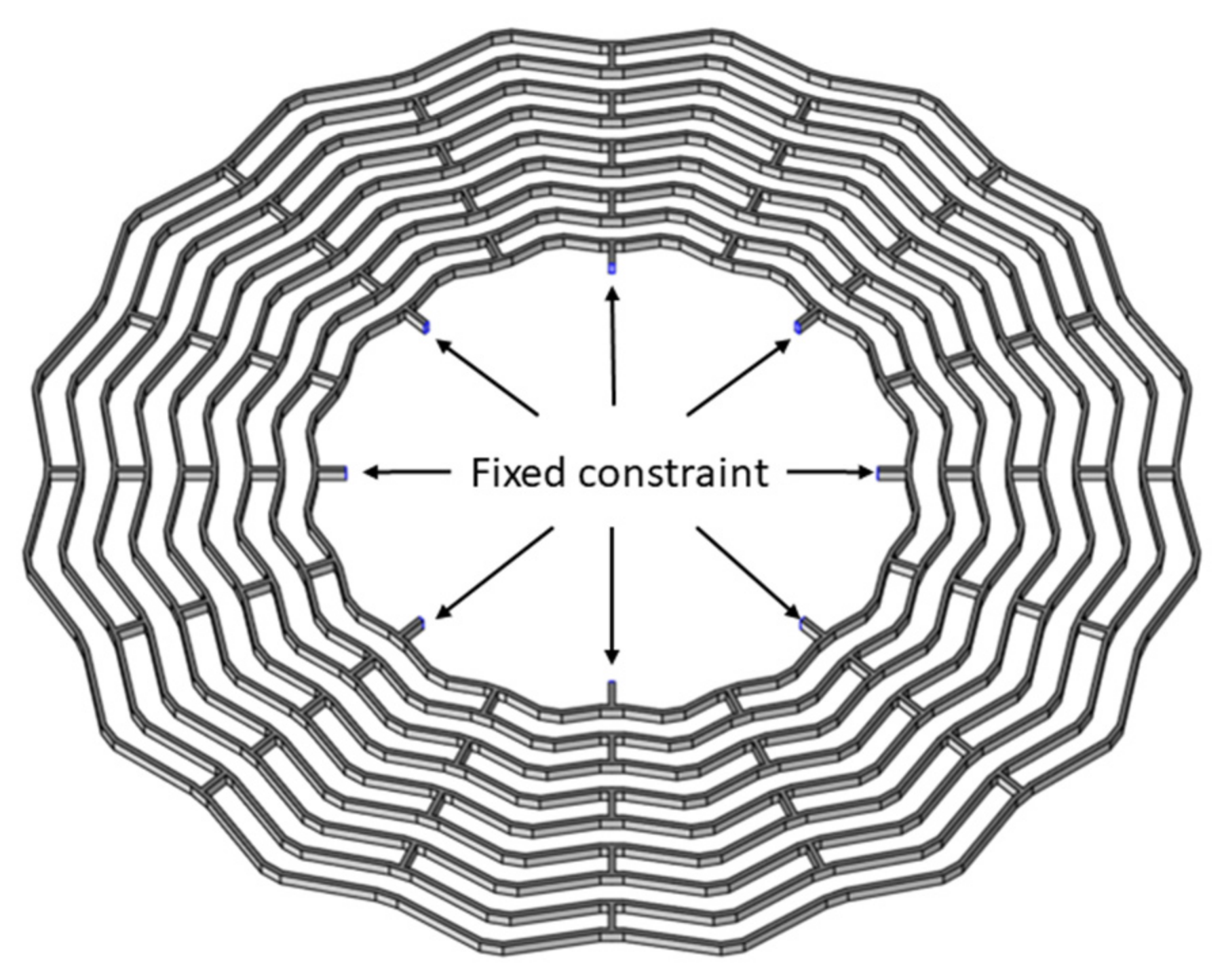
2.1. Structure Design

A GDR is topologically reformed from the traditional nested-ring disk resonator. It consists of a central anchor, concentric meander-shaped rings, spokes, and some electrodes around the resonator for driving and detection, as shown in Figure 1a. In contrast to an RDR, a GDR consists of two kinds of straight beams with different lengths instead of a concentric ring frame, and the lengths of all short beams are the same. Compared with the arc-shaped structure, the micromachining technique has higher adaptability to the linear structure [25]. Therefore, a GDR is more immune to fabrication error. The straight beams between the same layer are connected end to end, and different layers are interconnected by shared spokes. The meander-shaped rings are parallel to each other, and the spokes are perpendicular to the short beams at the junction with the rings. The side of the electrodes facing the resonator is paralleled to the outermost ring; it is more similar to a parallel plate capacitor. A GDR operates at the second elliptic degenerate mode, which is composed of a 0-degree mode and a 45-degree mode. Ideally, the two degenerate modes will have the same resonant frequency and similar modal shape, as shown in Figure 1b. When the gyroscope is operating, an electrostatic force is applied to the driving electrodes, and the 0-degree mode is stimulated to vibrate with a constant amplitude. Meanwhile, the vibration of the 45-degree mode is excited by the Coriolis force induced by the rotational angular velocity. The amplitude of the 45-degree mode is proportional to the input angular velocity, so the angular velocity can be measured by detecting the amplitude.
The basic structure parameters of the GDR studied in this paper included the radius of the anchor (r), radius of the outermost ring (R), long beam length (Llo), short beam length (Lsh), bending angle (θ), ring width (H), structure thickness (T), spoke length (L), and the number of rings (N), as shown in Figure 1a. Llo was determined by θ and Lsh. The resonant frequency of the GDR could be changed by adjusting θ and Lsh, while other structure parameters were determined. A low-resonant frequency would reduce the shock resistance of the device, and a higher resonant frequency would reduce the quality factor. In this paper, a compromise design scheme was chosen: θ was set as 130° and Lsh was set as 80 μm. The final design scheme is shown in Table 1.

2.2. Theory

Considering the asymmetry between the drive mode and sense mode, which is caused by the unequal stiffness and damping of the drive axis and the sense axis, the dynamic equation of the GDR can be expressed as follows [26]:
m e f f q ¨ A ( t ) + γ A q ˙ A ( t ) + k A q A ( t ) = F d r i v e m e f f q ¨ B ( t ) + γ B q ˙ B ( t ) + k B q B ( t ) = F C o r i o l i s
where γA, kA, and qA(t) are the damping coefficient, effective stiffness, and vibration displacement of the drive mode, respectively; γB, kB, and qB(t) are the damping coefficient, effective stiffness and vibration displacement of the sense mode, respectively; meff, Fdrive, and FCoriolis are the effective mass, driving force generated from applied voltage, and Coriolis force caused by input angular velocity, respectively.
When the DC part and double-frequency part in Fdrive is ignored, Fdrive can be simplified as [27]:
F d r i v e = F 0 sin ( w A t )
where F0 is the amplitude of drive force; w A = k A / m e f f is the resonant frequency of drive mode.
When angular velocity (Ω) is inputted, Coriolis force is generated, which is given as [28]:
F C o r i o l i s = 2 n A g m e f f Ω q ˙ A ( t )
where n is the circumferential wave number and Ag is the angular gain. For a DRG working at n = 2 wineglass mode, Equation (1) can be simplified according to Equations (2) and (3) as below:
m e f f q ¨ A ( t ) + γ A q ˙ A ( t ) + w A 2 m e f f q A ( t ) = F 0 sin ( w A t ) m e f f q ¨ B ( t ) + γ B q ˙ B ( t ) + w B 2 m e f f q B ( t ) = 4 A g m e f f Ω q ˙ A ( t )
where the w B = k B / m e f f is the resonant frequency of sense mode. The quality factor of the drive mode and sense mode can be given as:
Q A = ( w A m e f f ) / γ A Q B = ( w B m e f f ) / γ B
The driving amplitude (qA0) and sensing amplitude (qB0) can be derived from Equations (4) and (5):
q A 0 = Q A F 0 k A q B 0 = 4 A g m e f f Ω w A / k B [ 1 ( w A w B ) 2 ] 2 + ( 1 Q B w A w B ) 2
Then, the mechanical sensitivity Smech can be derived [29]:
S m e c h = 4 A g Q A F 0 w A k A ( w A 2 w B 2 ) 2 + ( w A w B Q B ) 2
The mechanical sensitivity can be maximized when there is no frequency split (wA = wB):
S m e c h = 4 Q 2 A g F 0 k A w 0
where w0 is the resonant frequency when there is no frequency split (w0 = wA = wB); Q is the quality factor when there is no frequency split (Q = QA = QB). It follows that the mechanical sensitivity should be improved by increasing the quality factor or reducing the frequency split.

2.3. FEM Simulations

To verify that the GDR has better performance and immunity to crystal orientation error than the RDR, the FEM was used to compare the two kinds of disk resonators through COMSOL Multiphysics. In the simulation process, the structure parameters of the GDR and RDR were the same.
We used the modal analysis and thermal expansion analysis of the software to solve the frequency and quality factor and used Equation (8) to solve the mechanical sensitivity. In order to reduce the computational effort, the constraints could be equated. The principle of equivalence was that there was no effect on the results of the FEM before and after equivalence. The central anchor was not displaced because it was fixed to the substrate, and no temperature gradient due to deformation was generated. Therefore, the constraint that the central anchor was fixed to the substrate could be equated: the central anchor was deleted and the fixed constraint was applied to the contact surface of the central anchor and the spokes, as shown in Figure 2. The material of the resonator was isotropic silicon, and the values of material parameters are shown in Table 2.
Without considering the frequency split, the resonant frequency, effective stiffness, QTED, and Smech of the GDR and RDR were compared, and the simulation results are shown in Figure 3. Compared with the RDR, the resonant frequency of the GDR was reduced by 33.1%, the effective stiffness was reduced by 61.7%, the QTED was increased by 19.9%, and the Smech was increased by 450%. The simulation results demonstrate that the overall performance of the GDR was better, its effective stiffness and resonant frequency were significantly reduced, and its QTED and Smech were significantly improved.
The elliptical flexural modes of DRGs have a high demand for symmetry. A single-crystal silicon wafer cut in the (111) plane (Si (111)) has isotropic mechanical properties, and it is an attractive material to manufacture DRGs. However, due to the limitations of microfabrication technology, there is an error in the process of fabricating Si (111) wafers, which is manifested by the fact that the crystal plane of actual (111) and ideal (111) is not the same; there is a pinch angle (α) between them, which can be expressed as the crystal orientation error. This error leads to the stiffness asymmetry of the resonator, which will increase the frequency split and reduce Smech. The finite element model of crystal orientation error can be built in COMSOL Multiphysics by performing tensor transformation [30]. The frequency mismatch between the drive mode and sense mode can be characterized by the relative frequency split:
η = | w A w B | ( w A + w B ) / 2
The value of wA and wB affected by the crystal orientation error of the GDR and RDR were calculated, and the effects are shown in Figure 4. It is clear that the increase in η was almost linear with increasing α. Therefore, the value of η can be expressed as follows:
η = λ α
where λ is the slope in Figure 4 and represents the sensitivity of the frequency split to a crystal orientation error. The values of λ could be calculated to be 1743.84 ppm/deg and 321.64 ppm/deg for the RDR and GDR, respectively. It is clear that the value of λ of the GDR was much smaller than the RDR, and it can be concluded that the GDR had higher immunity to crystal orientation error than the RDR.

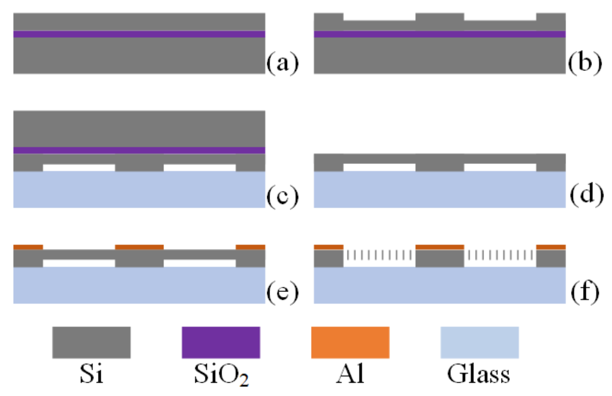
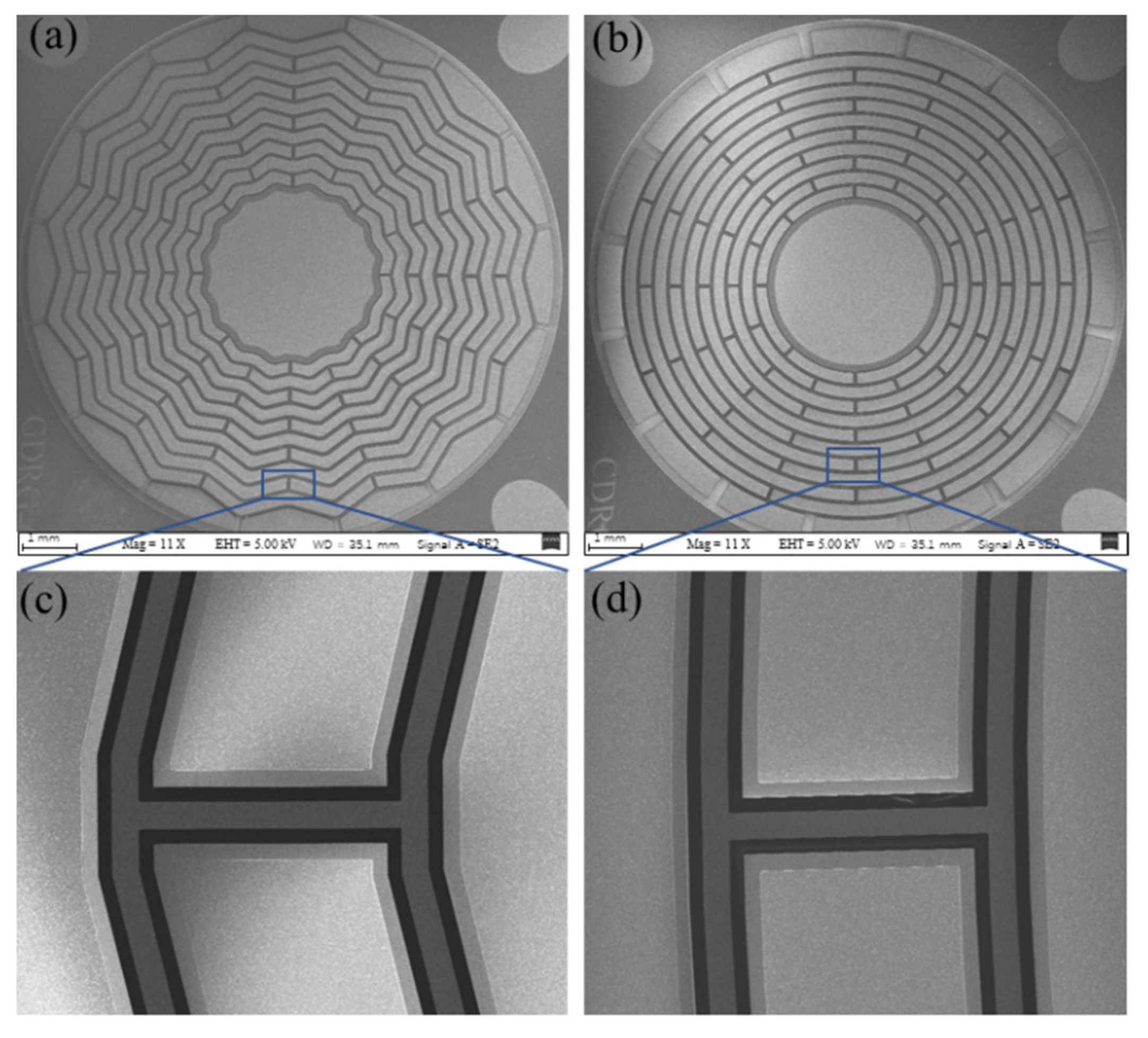
3. Fabrication Processes

The prototypes of the GDR and RDR with similar structure parameters were placed side-by-side on the same wafer and were fabricated using the Silicon-On-Insulator (SOI) process. The wafer-level fabrication process flow is shown in Figure 5. A 4-inch SOI wafer with a 60 μm (111) single-crystal silicon device layer was used as the structure wafer, and a 4-inch BF33 glass wafer was used as the substrate wafer. (a) The surface of the device layer of the SOI wafer was cleaned. (b) The device layer of the SOI wafer was etched via DRIE at a depth of 5 μm, and the anchor point support structure was fabricated. (c) Anodic bonding was carried out between the etched SOI wafer and the glass wafer. (d) The handle layer and buried oxygen layer were removed by polishing and etching. (e) A 400 nm thick aluminum (Al) layer was sputtered and patterned to form the wire bonding pads. (f) The resonator structure was formed in the device layer via photo-patterning and deep reactive ion etching (DRIE). The scanning electron microscope (SEM) images of the GDR and RDR are shown in Figure 6.

4. Resonator Characterization

A GDR and RDR with the same structure parameters were fabricated successfully. To further verify the performances of the GDR, a frequency response test and ring-down test were implemented. A schematic diagram of the experimental setup is shown in Figure 7. During the test, the resonators were placed in a vacuum probe station with a chamber temperature of 25 °C and a pressure of 5 Pa. Switch S1 was used to switch between two test modes.

4.1. Frequency Response Test

The frequency response test was performed to characterize the basic performances of the GDR and RDR. The drive electrodes of the resonators were connected to the output interface of the network analyzer (Keysight E5061B) which could produce a 5 Hz–10 MHz swept AC signal to drive the gyroscope. The capacitance signal of the resonator was converted into an AC signal by a charge amplifier. A band-pass filter was applied to reduce the noise, and then, the output signal was amplified. The output signal was collected by the input interface of the network analyzer (Keysight E5061B). Figure 8 shows the measurement results for the GDR and RDR. For the GDR, the resonant frequencies were 10.4163 kHz and 10.4254 kHz, and they were 16.6214 kHz and 16.6472 kHz for the RDR. The frequency split was 9.1 Hz for the GDR and 25.8 Hz for the RDR without tuning. The test results show that the symmetry of the GDR increased by about 64.7% compared with the RDR. This asymmetry came from a crystal orientation error and fabrication error, which could be reduced by structural trimming or electrostatic tuning. The improvement of the GDR over the RDR topology resulted in a lower effective stiffness and higher effective mass, and therefore a lower frequency. Additionally, the GDR had better immunity to crystal orientation error and fabrication error and therefore had a lower frequency split.

4.2. Ring-Down Test

With the drive signal of the resonator turned off, the resonant amplitude of the free decay followed the exponential law due to the presence of dissipation:
A ( t ) = A 0 exp ( t / τ )
where τ is the time constant which is directly proportional to the Q:
Q = π τ f 0
where f0 is the resonant frequency. The ring-down test could be used to evaluate Q more precisely. At first, the resonator was excited at the resonant frequency which was produced by a Signal Generator (AFG1062). After waiting for the oscillation to stabilize, the excitation signal was turned off and the decaying signal was recorded using a NI-DAQ capture card in LabVIEW. Finally, the data were calculated in MATLAB and the envelope was obtained. τ was calculated by fitting the envelope with Equation (11), and Q could be estimated based on Equation (12). The ring-down test result is shown in Figure 8. The decaying time constant τ of the GDR was determined to be 0.59 s, and Q was calculated to be 19.2 k. The τ of the RDR was 0.25 s, and Q was calculated to be 13.2 k. The experimental results show that the GDR had better performance than the RDR.

5. Conclusions

This paper reported on the design, fabrication, and characterization of a GDR. The relationship between Smech and Q and frequency split was derived. The FEM was used to verify that the GDR had a lower resonant frequency and effective stiffness, higher Q and Smech, and higher immunity to crystal orientation error than the RDR. The designed GDR and the traditional RDR with the same structure parameters were fabricated using the SOI process, and the resonator performances were characterized. For the GDR fabricated in this paper, the frequency split was decreased by 64.7%, and Q and τ were improved by 145% and 236%, compared with the RDR. The experimental results show that the proposed design is feasible in and applicable to the creation of a high-performance gyroscope. Moreover, by adjusting the structure parameters and keeping the resonator under an ultra-vacuum condition, the performance of the GDR could be further improved.

Author Contributions

Supervision, plan, and funding acquisition, W.Z.; writing, editing, design, fabrication and experiment L.G.; FEM simulation, J.F.; data acquisition and processing, Z.Z. All authors have read and agreed to the published version of the manuscript.

Funding

This research received no external funding.

Institutional Review Board Statement

Not applicable.

Informed Consent Statement

Not applicable.

Data Availability Statement

Not applicable.

Acknowledgments

The authors would like to thank the cleanroom staff at the Advanced Electronic Materials and Devices (AEMD) platform for their help in device fabrication.

Conflicts of Interest

The authors declare no conflict of interest.

References

  1. Lammel, G. The Future of Mems Sensors in Our Connected World. In Proceedings of the 2015 28th IEEE International Conference on Micro Electro Mechanical Systems (Mems 2015), Estoril, Portugal, 18–22 January 2015; pp. 61–64. [Google Scholar]
  2. Challoner, A.D.; Howard, H.G.; Liu, J.Y. Boeing disc resonator gyroscope. In Proceedings of the 2014 IEEE/ION Position, Location and Navigation Symposium-PLANS 2014, Monterey, CA, USA, 5–8 May 2014. [Google Scholar]
  3. Shkel, A.M. Type I and Type II Micromachined Vibratory Gyroscopes. In Proceedings of the 2006 IEEE/Ion. Position, Location and Navigation Symposium, San Diego, CA, USA, 25–27 April 2006;–3; Volume 1–3, pp. 586–593. [Google Scholar]
  4. Feng, J.; Zhang, W.P.; Gu, L.T.; Liu, Z.Y. Design of a novel gear-like disk resonator gyroscope with high mechanical sensitivity. Microsyst. Technol. 2021, 27, 2715–2722. [Google Scholar] [CrossRef]
  5. Gerrard, D.D.; Rodriguez, J.; Ortiz, L.C.; Chandorkar, S.A.; Flader, I.B.; Chen, Y.H.; Shin, D.D.; Kenny, T.W. Manipulation of Heat Flux Paths in Thermo-Elastically Damped Resonators for Q Optimization. In Proceedings of the 30th IEEE International Conference on Micro Electro. Mechanical Systems (Mems 2017), Las Vegas, NV, USA, 22–26 January 2017; pp. 1130–1133. [Google Scholar]
  6. Xia, D.Z.; Huang, L.C.; Xu, L.; Gao, H.Y. Structural Analysis of Disk Resonance Gyroscope. Micromachines 2017, 8, 296. [Google Scholar] [CrossRef] [PubMed] [Green Version]
  7. Gerrard, D.D.; Ahn, C.H.; Flader, I.B.; Chen, Y.H.; Ng, E.J.; Yang, Y.S.; Kenny, T.W. Q-Factor Optimization in Disk Resonator Gyroscopes Via Geometric Parameterization. In Proceedings of the 2016 IEEE 29th International Conference on Micro Electro. Mechanical Systems (Mems), Shanghai, China, 24–28 January 2016; pp. 994–997. [Google Scholar]
  8. Li, Q.S.; Xiao, D.B.; Zhou, X.; Hou, Z.Q.; Xu, Y.; Wu, X.Z. Quality Factor Improvement in the Disk Resonator Gyroscope by Optimizing the Spoke Length Distribution. J. Microelectromech. Syst. 2018, 27, 414–423. [Google Scholar] [CrossRef]
  9. Li, Q.S.; Xiao, D.B.; Zhou, X.; Xu, Y.; Zhuo, M.; Hou, Z.G.; He, K.X.; Zhang, Y.M.; Wu, X.Z. 0.04 degree-per-hour MEMS disk resonator gyroscope with high-quality factor (510 k) and long decaying time constant (74.9 s). Microsyst. Nanoeng. 2018, 4, 32. [Google Scholar] [CrossRef] [PubMed]
  10. Zhou, X.; Luo, X.; Xiao, D.; Li, Q.; Hou, Z.; He, K.; Wu, Y.; Wu, X. Investigation on the way of adding lumped masses on disk resonator gyroscope. In Proceedings of the 2017 IEEE Sensors, Glasgow, UK, 29 October–1 November 2017. [Google Scholar]
  11. Zhou, X.; Xiao, D.; Wu, X.; Wu, Y.; Hou, Z.; He, K.; Li, Q. Stiffness-mass decoupled silicon disk resonator for high resolution gyroscopic application with long decay time constant (8.695 s). Appl. Phys. Lett. 2016, 109, 263501. [Google Scholar] [CrossRef]
  12. Ko, S.D.; Hamelin, B.; Yang, J.; Ayazi, F. High-Q Monocrystalline Silicon Carbide Disk Resonators Fabricated Using Drie of Thick Sic-on-Insulator Substrates. In Proceedings of the 2018 IEEE Micro Electro. Mechanical Systems (Mems), Belfast, UK, 21–25 January 2018; pp. 6–999. [Google Scholar]
  13. Giner, J.; Maeda, D.; Ono, K.; Shkel, A.M.; Sekiguchi, T. MEMS Gyroscope with Concentrated Springs Suspensions Demonstrating Single Digit Frequency Split and Temperature Robustness. J. Microelectromech. Syst. 2019, 28, 25–35. [Google Scholar] [CrossRef]
  14. Xu, Y.; Li, Q.; Wang, P.; Zhang, Y.; Zhou, X.; Yu, L.; Wu, X.; Xiao, D. 0.015 Degree-Per-Hour Honeycomb Disk Resonator Gyroscope. IEEE Sens. J. 2020, 21, 7326–7338. [Google Scholar] [CrossRef]
  15. Fan, B.; Guo, S.W.; Cheng, M.M.; Yu, L.; Zhou, M.; Hu, W.Y.; Chen, Z.A.; Xu, D.C. A Novel High-Symmetry Cobweb-Like Disk Resonator Gyroscope. IEEE Sens. J. 2019, 19, 10289–10297. [Google Scholar] [CrossRef]
  16. Efimovskaya, A.; Wang, D.; Lin, Y.-W.; Shkel, A.M. Electrostatic compensation of structural imperfections in dynamically amplified dual-mass gyroscope. Sens. Actuators A Phys. 2018, 275, 99–108. [Google Scholar] [CrossRef]
  17. Xiao, D.B.; Yu, D.C.; Zhou, X.; Hou, Z.Q.; He, H.H.; Wu, X.Z. Frequency Tuning of a Disk Resonator Gyroscope via Stiffness Perturbation. IEEE Sens. J. 2017, 17, 4725–4734. [Google Scholar] [CrossRef]
  18. Dong Joon, K.; M’Closkey, R.T. A systematic method for tuning the dynamics of electrostatically actuated vibratory gyros. IEEE Trans. Control Syst. Technol. 2006, 14, 69–81. [Google Scholar] [CrossRef]
  19. Gallacher, B.J.; Hedley, J.; Burdess, J.S.; Harris, A.J.; Rickard, A.; King, D.O. Electrostatic correction of structural imperfections present in a microring gyroscope. J. Microelectromech. Syst. 2005, 14, 221–234. [Google Scholar] [CrossRef]
  20. Taheri-Tehrani, P.; Kline, M.; Izyumin, I.; Eminoglu, B.; Yeh, Y.-C.; Yang, Y.; Chen, Y.; Flader, I.; Ng, E.J.; Kenny, T.W.; et al. Epitaxially-encapsulated quad mass gyroscope with nonlinearity compensation. In Proceedings of the 2016 IEEE 29th International Conference on Micro Electro Mechanical Systems (MEMS), Shanghai, China, 24–28 January 2016. [Google Scholar]
  21. Songqi, H.; Hongjuan, C.; Kun, H.; Zhanqiang, H.; Peng, C.; Dingbang, X.; Xuezhong, W. A method of structural trimming to reduce mode coupling error for micro-gyroscopes. In Proceedings of the 8th Annual IEEE International Conference on Nano/Micro Engineered and Molecular Systems, Suzhou, China, 7–10 April 2013. [Google Scholar]
  22. Wang, Y.; Asadian, M.H.; Shkel, A.M. Compensation of frequency split by directional lapping in fused quartz micro wineglass resonators. J. Micromech. Microeng. 2018, 28, 095001. [Google Scholar] [CrossRef] [Green Version]
  23. Behbahani, A.H.; Kim, D.; Stupar, P.; DeNatale, J.; M’Closkey, R.T. Tailored Etch Profiles for Wafer-Level Frequency Tuning of Axisymmetric Resonators. J. Microelectromech. Syst. 2017, 26, 333–343. [Google Scholar] [CrossRef] [Green Version]
  24. Senkal, D.; Ahamed, M.J.; Trusov, A.A.; Shkel, A.M. Achieving Sub-Hz Frequency Symmetry in Micro-Glassblown Wineglass Resonators. J. Microelectromech. Syst. 2014, 23, 30–38. [Google Scholar] [CrossRef] [Green Version]
  25. Hsu, T.-R. MEMS and Microsystems: Design, Manufacture, and Nanoscale Engineering; John Wiley & Sons: Hoboken, NJ, USA, 2008. [Google Scholar]
  26. Acar, C.; Shkel, A. MEMS Vibratory Gyroscopes: Structural Approaches to Improve Robustness; Springer Science & Business Media: Berlin, Germany, 2008. [Google Scholar]
  27. Su, T.-H. Approaches for LOW Noise Sensing in MEMS Disk Gyros; University of California: Berkeley, CA, USA, 2016. [Google Scholar]
  28. Cho, J.Y. High-Performance Micromachined Vibratory Rate-and Rate-Integrating Gyroscopes. Ph.D. Thesis, University of Michigan, Ann Arbor, MI, USA, 2012. [Google Scholar]
  29. Ayazi, F.; Najafi, K. A HARPSS polysilicon vibrating ring gyroscope. J. Microelectromech. Syst. 2001, 10, 169–179. [Google Scholar] [CrossRef] [Green Version]
  30. Chang, C.-O.; Chang, G.-E.; Chou, C.-S.; Chien, W.-T.C.; Chen, P.-C. In-plane free vibration of a single-crystal silicon ring. Int. J. Solids Struct. 2008, 45, 6114–6132. [Google Scholar] [CrossRef] [Green Version]
Figure 1. Design strategy: (a) the structure of GDR; (b) the working mode of GDR.
Applsci 12 07342 g001
Figure 2. The equivalent constraint in COMSOL Multiphysics.
Applsci 12 07342 g002
Figure 3. Performances comparison between GDR and RDR.
Applsci 12 07342 g003
Figure 4. Effects of α on frequency split.
Applsci 12 07342 g004
Figure 5. Fabrication process flow of GDR and RDR.
Applsci 12 07342 g005
Figure 6. SEM images of fabricated GDR and RDR: (a) overview of GDR; (b) overview of RDR; (c) detailed view of GDR; (d) detailed view of RDR.
Applsci 12 07342 g006
Figure 7. Experimental setup for frequency response test and ring-down test.
Applsci 12 07342 g007
Figure 8. Experiment results of frequency response and ring-down test: (a) GDR. (b) RDR.
Applsci 12 07342 g008
Table 1. Structure parameters of GDR.
Structure ParametersValue
Anchor radius (r)1300 μm
Outer radius (R)3615 μm
Short beam length (Lsh)80 μm
Bending angle (θ)130°
Ring width (H)20 μm
Structure thickness (T)60 μm
Spoke length (L)190 μm
Ring number (N)10
Table 2. The value of material parameters used in FEM calculation.
Material ParametersValue
Elastic modulus (E)170 GPa
Thermal conductivity (κ)130 W/(m·K)
Coefficient of thermal expansion (αT)2.6 × 10⁻⁶ 1/K
Constant pressure heat capacity (Cp)700 J/(kg·K)
Density (ρ)2329 kg/m3
Poisson’s ratio (υ)0.28
Publisher’s Note: MDPI stays neutral with regard to jurisdictional claims in published maps and institutional affiliations.

