Article

Research on a Fiber Corner Compensation Algorithm in a 3D Printing Layer of Continuous Fiber-Reinforced Composite Materials

1
School of Mechanical Engineering, University of Science and Technology Beijing, Beijing 100083, China
2
School of Mechanical Engineering, Jiangsu University of Science and Technology, Zhenjiang 212003, China
*
Author to whom correspondence should be addressed.
Appl. Sci. 2022, 12(13), 6687; https://doi.org/10.3390/app12136687
Submission received: 24 May 2022 / Revised: 26 June 2022 / Accepted: 30 June 2022 / Published: 1 July 2022
(This article belongs to the Section Additive Manufacturing Technologies)

Abstract

:
Fused filament fabrication (FFF) 3D printing technology for continuous fiber-reinforced composite (CFRC) printing has become a trend. This article is based on ‘independent extrusion’ FFF CFRC printing. The continuous fiber-reinforced filament (CFRF) printing solution is the contour offset method for obtaining executable g-code. When the CFRCF prints at the corner, it is found that the actual CFRC printing trajectory is inconsistent with the ideal laying trajectory. The causes of the error are analyzed, and an angle optimization algorithm is proposed. The corner optimization algorithm is verified by theoretical analysis and experimental analysis. From the experimental results, the corner optimization algorithm improves the 30° angle fit of CFRF printing by 90% and reliability has also been improved. When the printing length is 127,200 mm, there are 960 printing corners, and the failure rate is 0.

1. Introduction

Additive manufacturing (AM) is the most promising method for manufacturing complex structural parts [1,2,3]. Compared with traditional manufacturing methods, AM technology can shorten the design and manufacturing cycle, reduce production costs, and improve competitiveness [4,5]. Among many AM technologies, fused filament fabrication (FFF) has attracted much attention due to its low cost and ease of use [6]. The low strength of traditional thermoplastic printing material limits its industrial application [7,8,9]. In order to make printed parts for direct application in industrial products, many scholars have studied how to improve printing strength [10]. Fiber particles or short fibers have been added to thermoplastic materials to make fiber-reinforced thermoplastic composites [11,12]. However, these materials have failed to meet the requirements for industrial applications [5]. In recent years, many scholars have tried to apply the composite material preparation method (CFRC) from the aerospace manufacturing field to the AM field and have tried to embed continuous fibers into polymer materials to improve their strength, making great progress.
There are two main ways of 3D printing continuous fiber-reinforced composite materials: one is “co-extrusion”; the other is “independent extrusion”. The “co-extrusion” printing method involves the injection of continuous fiber filaments and thermoplastic resin printing consumables directly into a high-temperature print head at the same time. Once the continuous fibers are impregnated and wrapped by the molten resin material in the print head, they are extruded from the print head together. The “co-extrusion” printing principle is shown in Figure 1a. The “independent extrusion” method is to pre-manufacture the composite material pre-impregnated with continuous reinforcing fibers and a thermoplastic resin matrix and then use different print heads to print the resin matrix material and prepreg. The “independent extrusion” printing principle is shown in Figure 1b. Wang et al. studied the effect of process parameters on the mechanical properties of the printed parts by pre-preparing CGFRF/PLA and using the printing method of “independent extrusion”. The tensile and flexural strengths of the specimens were increased by 400% and 204% when the fiber volume fractions were about 5.21% and 6.24%, respectively [13]. Chacón et al. studied the influences of process parameters, such as fiber laying direction and fiber volume fraction, on the mechanical properties of CFRC samples and compared the effects of carbon fiber, glass fiber, and Kevlar on enhancing PA [14]. Goh et al. studied the mechanical properties of carbon fiber and glass fiber-reinforced composites and discussed in detail the fracture behavior of each test sample [15]. Dickson et al. studied the failure mode of CFRC and found that continuous fibers absorbed a large amount of load and that the matrix would bear impact load when the continuous fibers failed [16]. However, they only studied the effect of process parameters on the performance index of CFRC.
Slice processing is a key technology in 3D printing that transforms 3D models into executable code, which determines the quality and efficiency of printed products. Therefore, the slicing process needs to integrate various factors, such as filling path [17], directional characteristics, material characteristics, slicing efficiency, printing time, and so on. Compared with traditional FFF, due to the unique continuity and directionality of CFRF, the regulation of the filling path is particularly important in CFRF printing. It is necessary to design an appropriate printing path to ensure molding quality and printing efficiency, as well as facilitate program implementation. Finally, the g-code for printing is generated by slicing software. At present, there are a few mature commercial slicing software systems on the market, mainly the ‘Eiger’ system of the Markforged company [18] and the ‘Aura’ system of the Anisoprint company [19]. However, they are still not flexible, and the process parameters that can be regulated are relatively limited.
Three-dimensional printing path planning algorithms mainly include contour offset scanning, reciprocating parallel scanning, layer-to-layer change-of-direction scanning, and composite path scanning algorithms [17]. Among them, contour offset scanning is prone to the problem of contour loop intersection when forming complex parts [20,21]. The scanning distance of the reciprocating parallel scanning algorithm usually uses a fixed value, which is prone to large errors [22,23]. To solve the problem of CFRC printing path jump, Ma et al. identified the jump point of 3D printing based on the g-code file after 3D model slice processing [24]. Based on the distance relationship between the 3D path coordinates and the remote cutting device, accurate matching between the printing jump point and the fiber cutting point was realized, and the continuous fiber remote cutting process was carried out. For 3D model slicing processing, the traditional method is linear reciprocating filling, resulting in many starting point paths, and it is not suitable for continuous fiber 3D printing problems. Tan et al. put forward the direction of the adjustable “Z” word filling algorithm, using the dynamic filling angle adjustable parallel scan filling mode and group-related line in accordance with the principle of parity connection, reduce the jump, maximizing the path [25].
However, current slicing software for FFF printing cannot directly generate continuous fiber tracks, and the few foreign providers of continuous fiber slicing software, such as Markforged, only provide services to users who buy their 3D printers. Based on the development of continuous fiber 3D printing slicing software, this paper analyzes the causes of the problems encountered in the laying of CFRF and puts forward effective solutions to ensure the stability and reliability of the printing process and that the laying effect is accurate.

2. Research Base

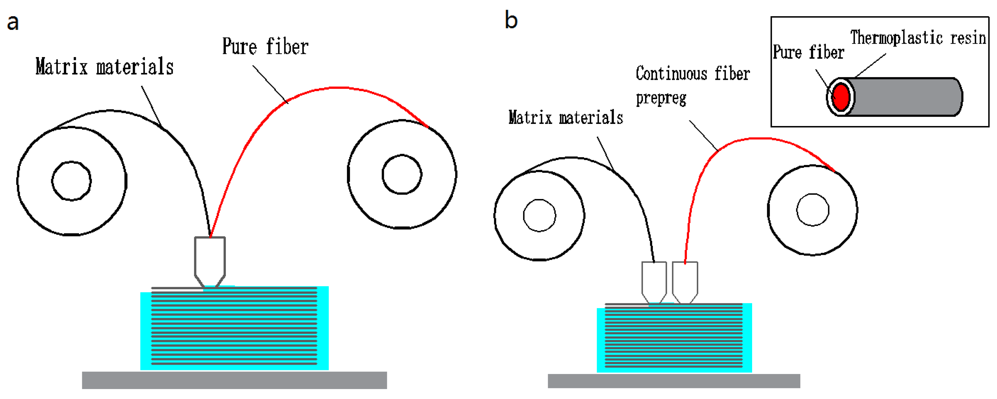
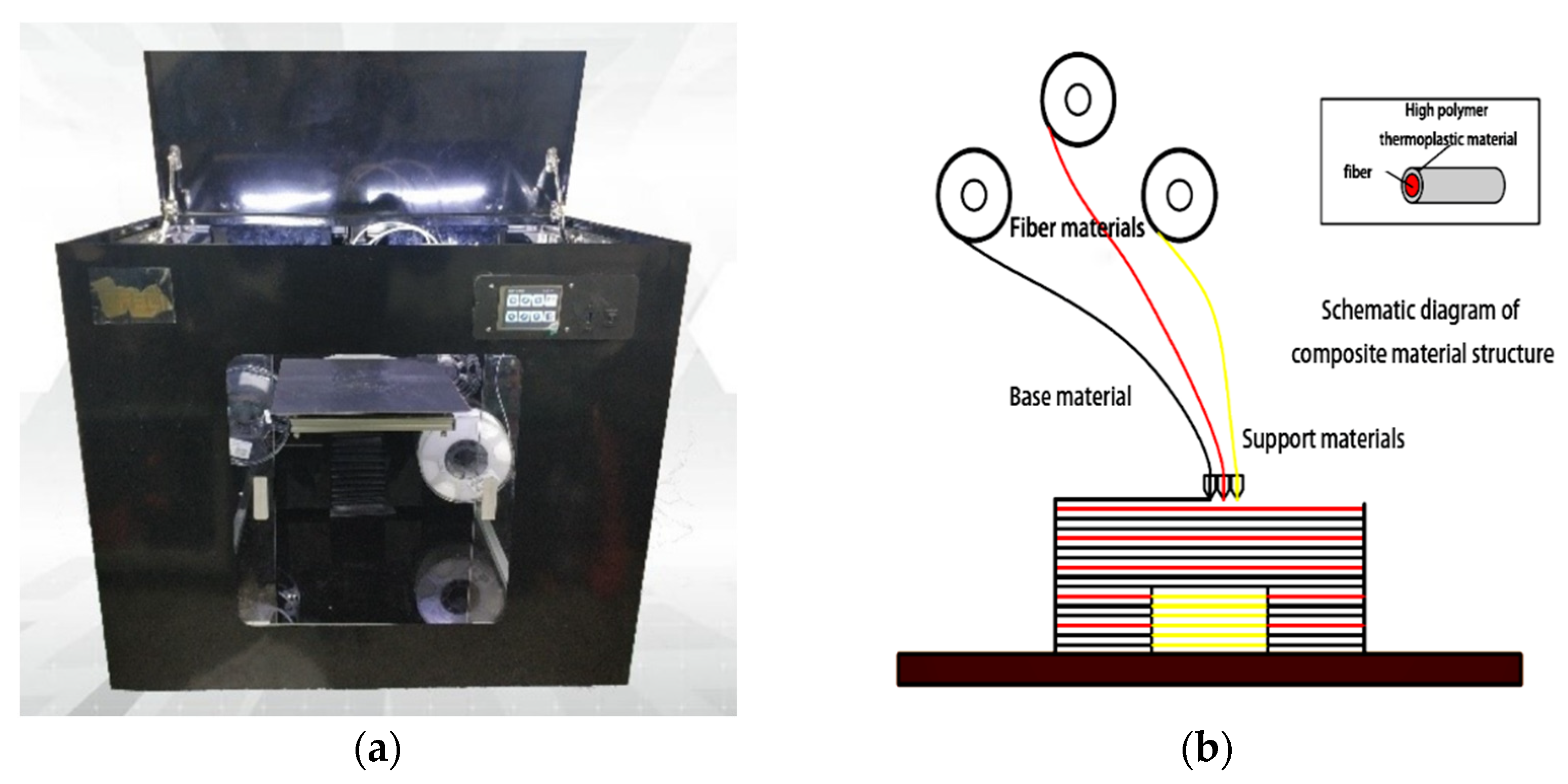
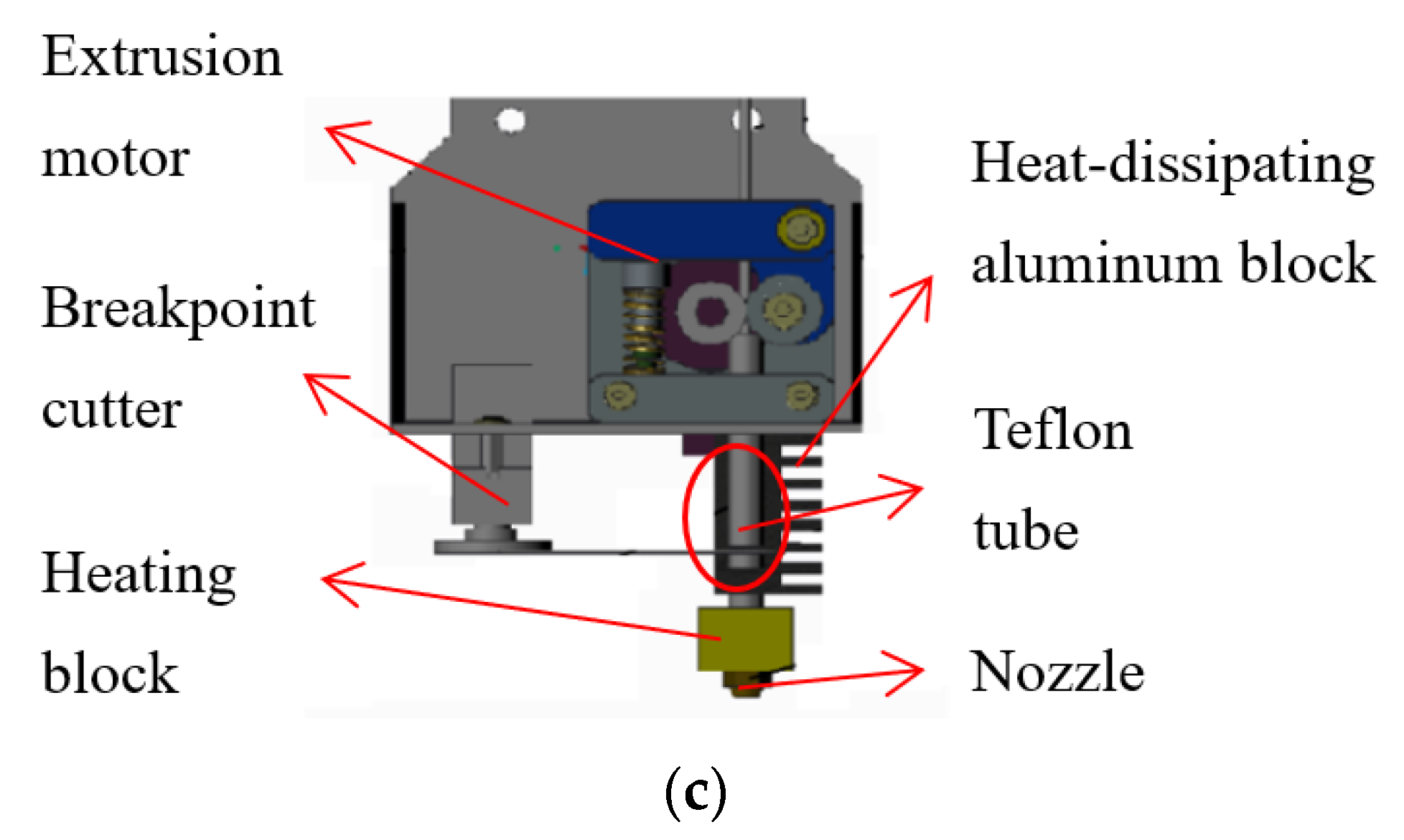
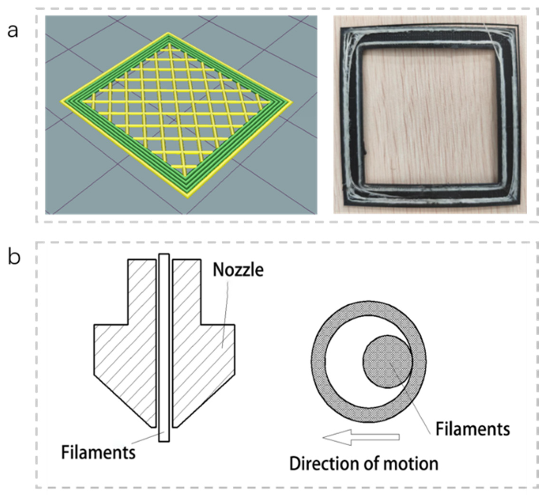
2.1. “Independent Extrusion” Printing Principle of FFF CFRC

This study is based on the “independent extrusion” FFF printing method [18], which separates the manufacturing process of continuous fiber filaments from the printing process to reduce the complexity of the printing system control and increase the reliability of the printing process. The 3D printing process for CFRC is as follows: Firstly, several layers of matrix polymeric thermoplastic materials are printed (such as ABS, PLA, or nylon). The fiber layer is then printed, and the CFRF containing fibers (carbon fibers (CFs) or glass fibers (GFs), etc.) is laid on the matrix material layer. Since the outer layer of the CFRF is coated with sizing agent polymer thermoplastic material, it is in a molten state of high viscosity liquid when it is ejected, so it easily bonds with the existing matrix material. Due to the CFRF radius of curvature and fiber filling volume constraints, the same fiber layer of the part cannot be full of CFRF, the void portion still being filled with the matrix material; therefore, at least two print heads need to be switched constantly during the printing process.
In this study, the 3D printer of CFRC is self-made, as shown in Figure 2. The equipment has three independent printing heads; they print matrix material, support material, and CFRF, respectively. The machine parameters are shown in Table 1. In addition, there are the printing function of the motion mechanism and control system and other modules. Figure 2b shows the working principle of the printing heads, and the printing head for CFRF is shown in Figure 2c.

2.2. Principle of the CFRF Filling Algorithm

At present, there is no uniform trajectory layout standard for CFRF printing. In the method of full filling, a certain layer is covered with CFRF with some pattern (mostly reciprocating filling) which is then covered by the next layer of substrate, so that the fiber layer is located in the interlayer of the two layers of substrate, as shown in Figure 3a.
The full filling method has the characteristics of the simple laying method—easy calculation and fiber axial reinforcement. In the experimental stage, it is often only used for test, but it is difficult to use as a filling method for actual printing. This study is based on the use of the contour offset method as the generation method of the CFRF layer track [20]. The contour offset method is used to obtain the laying track of fiber by shifting the outermost contour of the print body inward. The number of fiber loops needed to offset is set as a parameter for printing, as shown in Figure 3b.
The contour offset method can greatly shorten the path, ensuring the strength of printing parts. In order to reduce the weight of the printing parts, it is common to use a low filling rate inside the parts without affecting surface quality. The surface profile is densely filled—the filling rate is 100%—and continuous fiber is used as reinforcement instead of resin material.

2.3. Present Situation and Analysis

The slicing software uses the contour offset method to generate g-code for actual printing [26], and the problems shown in Figure 4a appeared in the actual printing test. It can be seen that the finished product as-printed has many defects, especially in the right-angle turning area. In the initial stage, it can print normally, but in the later stage, it deviates from the original track seriously, with the result that the length of the extruded filament is not equal to the actual laying length, which may cause nozzle blockage. Figure 4b is a feeding diagram of CFRF printing. It can be seen that the diameter of the CFRF is inconsistent with the diameter of the nozzle, and there is a certain diametrical difference between the two. As a result, in the printing corner, the actual laying track of the fiber is inclined to the inner region of the corner, resulting in inconsistency between the actual laying track and the theoretical laying track. Therefore, the offset fiber trajectory needs to be further optimized.

3. Optimization and Analysis

3.1. Corner Optimization Theory

In order to solve the problem of corner deviation in CFRF printing, a compensation algorithm was proposed. Figure 5a shows a corner trajectory diagram of CFRF printing. The radius difference between the fiber nozzle and the fiber filament is D. The following cases are discussed:
(1)
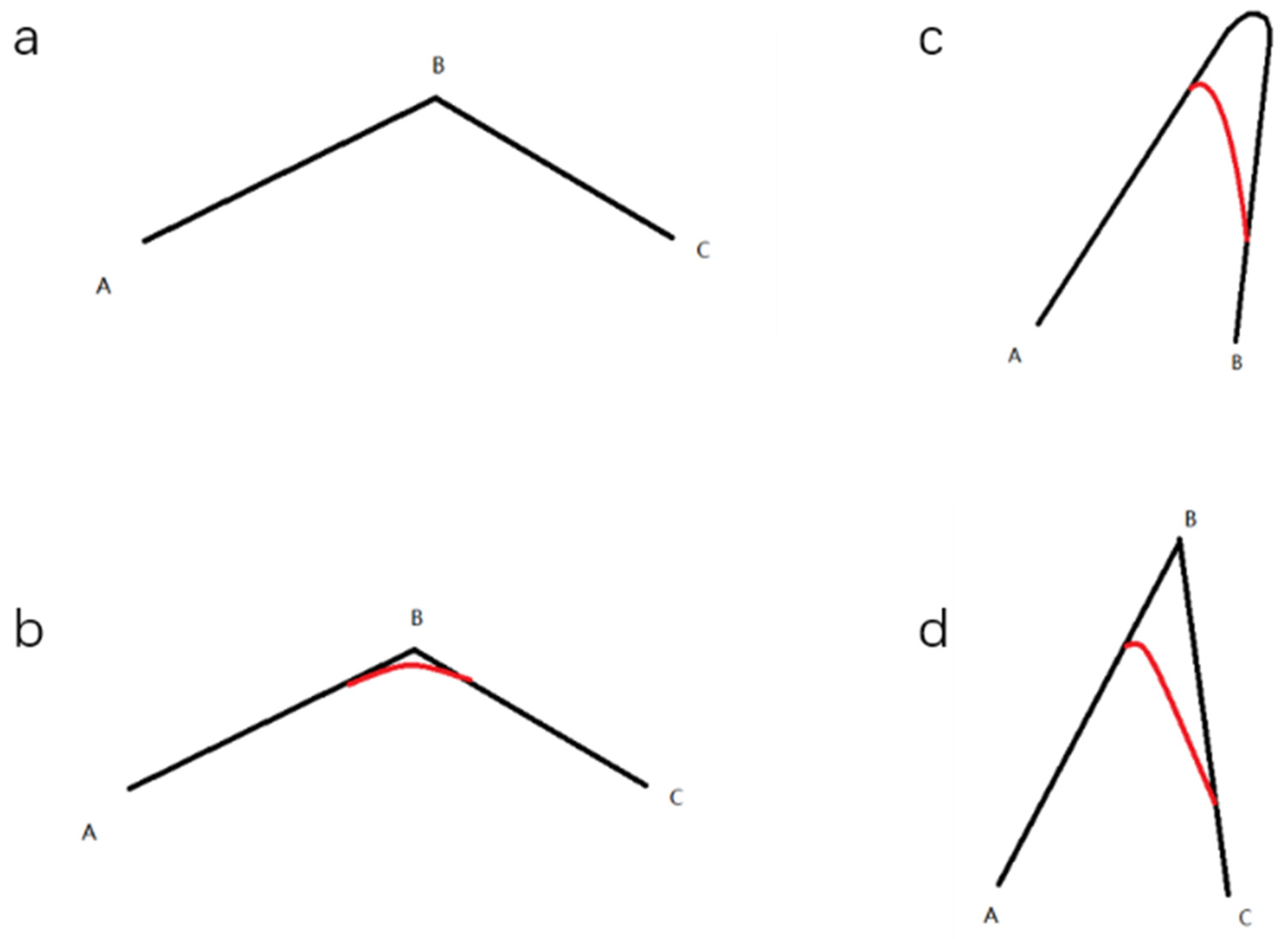
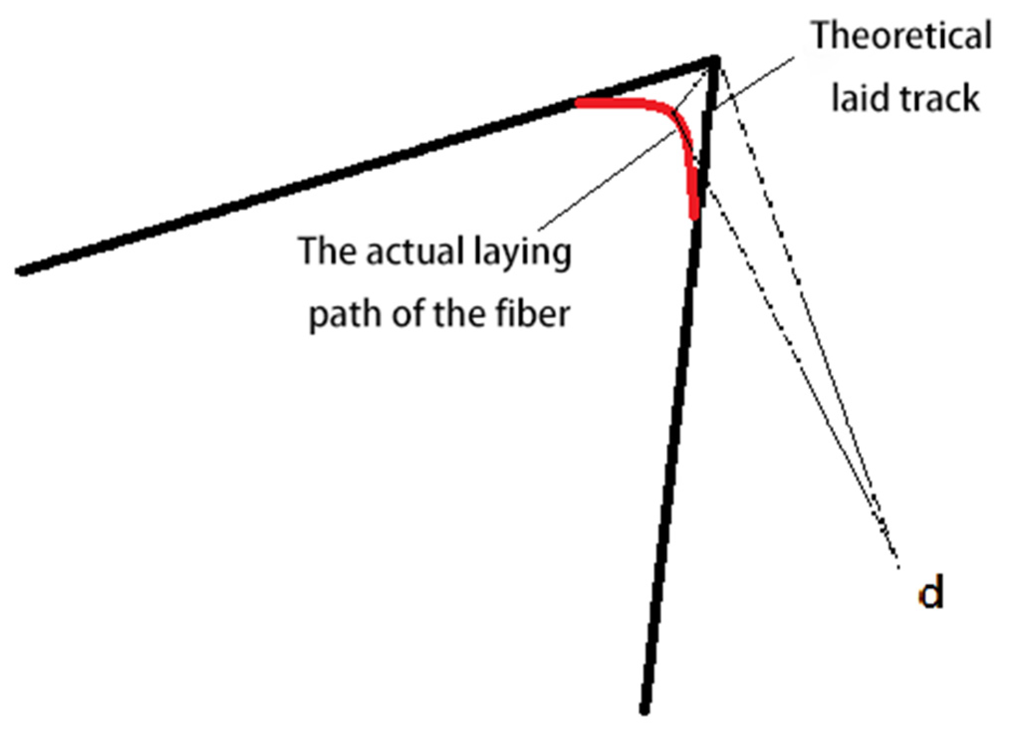
The length of BC is much larger than d, and the angle B is obtuse: The comparison between the actual printing condition and the ideal path is shown in Figure 5b. As can be seen from Figure 5b, the error value of BC is much smaller than d due to the large corner angle, which has little impact on the path characteristics and small error accumulation. In this case, there is no need for optimization.
(2)
Length of BC and close to or less than d, and angle B is the obtuse angle: the situation of the actual printing compared with the ideal path as shown in Figure 5c, this situation often occurs on the minimum curvature radius of the circular arc (the circular slice in the path of the line for the multiple angle is close to 180°). It can be seen from the figure that, due to the limited side length, it is not sufficient to pull the CFRF to the correct path in time, resulting in a large error. When this happens on the minimum curvature radius of the circular arc, there will often be many similar corner points in the follow-up, which means that the error will continue to accumulate. So, there is a need to optimize paths in this situation.
(3)
Angle B is an acute angle: The comparison between the actual printing condition and the ideal path is shown in Figure 5c. It can be seen from the figure that this condition has a great influence on the accuracy of path characteristics, and the error generated is close to d, which is also large, so it needs to be optimized.
The above three cases have included all corner cases, so it is necessary to carry out targeted optimization for situations (2) and (3). The optimization method is to make the actual printing path conform to the original ideal path completely or, as far as possible, by modifying the print path. The optimization is as follows:
(1)
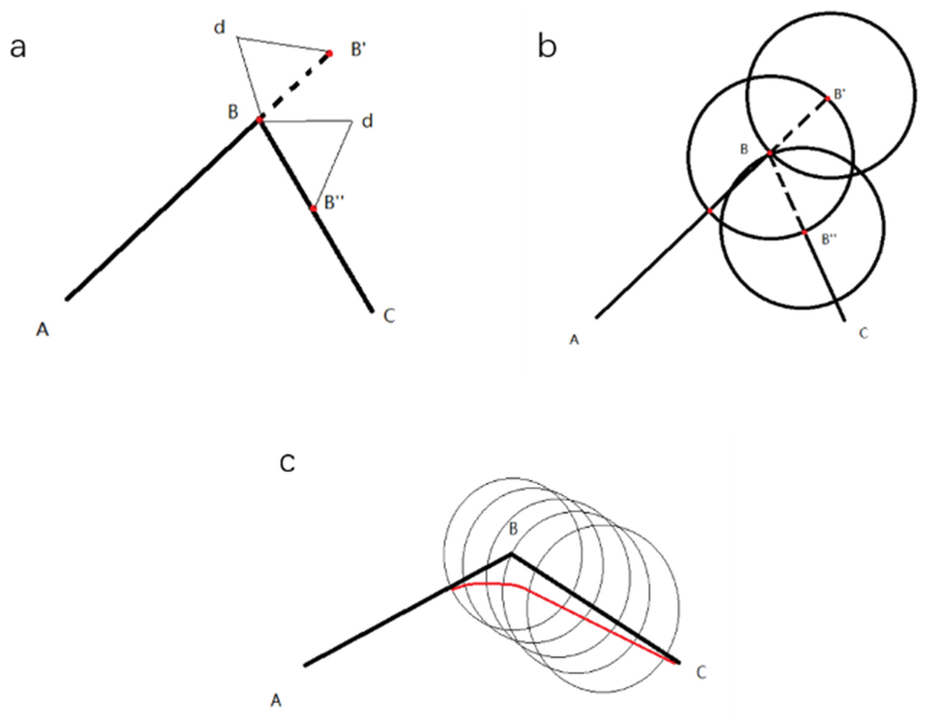
Optimization of the acute angle: by analyzing the comparison between the theoretical path and practical path of the acute angle, the compensation-regression optimization method is adopted, that is, one edge before the corner is extended from point B with a length of d to obtain the new point B’, and the next edge is extended with a length of d from point B to obtain B’’, as shown in Figure 6a.
The optimized printing path is A–B’–B–B’’, in which the B’–B’’ section is empty and does not feed. In this way, it can be ensured that the center of the CFRF cross section is exactly located at the theoretical point B when the nozzle goes to point B’. When the nozzle returns to point B, the fiber still stays at point B due to an absence of force. When the nozzle comes to point B’’, the nozzle contacts the fiber again and begins to drive the fiber to move to the next point C. The whole process has no theoretical error, as shown in Figure 6b.
The trip between this point and the previous point is a blank trip, which is not fed to the CFRF, and an identification program is added at the subsequent g-code generation.
(2)
Small arc optimization: small arc optimization requires that attention be paid to two points: first, the small arc corners are many, if they are the same as in the acute angle optimization method, which will greatly increase the amount of data, increase the g-code, increase the printing time, and may also cause machine vibration. Second, the error caused by a single small corner is not big; its main influence lies in the error accumulation of all corners in the whole circle. According to the above characteristics, the following optimization method is proposed: extend the original vertex B by d along the direction of AB, and the new point B’ obtained will replace point B.
According to Figure 6c, the fiber section is simplified to a point and the nozzle radius is reduced to d accordingly, to meet the requirements of the original motion mechanism. A mathematical model is established for the actual motion trajectory of the fiber at the corner, which meets the following requirements:
( x v t ) 2 + y 2 = R 2 y x = y ( x v t ) x ( 0 ) = n 1 y ( 0 ) = n 2
x is the x coordinate at time t of the fiber, y is the y coordinate at time t of the fiber, x is the x coordinate at time t of the nozzle center, y is the y coordinate at time t of the nozzle center, the R-value is d, v is the nozzle moving speed, and n1 and n2 are determined by corner angle and are known values that can be calculated.
According to the above formula, the moving direction of the nozzle at each inflection point should be the tangent direction of the point on the arc. The position should be ahead of the original vertex d in that direction. The tangent direction should be the average of the direction vectors of the front and rear edges of the vertex. Since the corners of the small arc are obtuse angles, the difference between the direction vectors of the front and rear sides of the vertex is small, so the direction of the front edge of the vertex can be selected as the compensation direction. There are still errors in this optimization method, but the error is far less than d when the corner is obtuse, which belongs to the acceptable range. The flowchart for optimizing different printing angles by using the corner optimization algorithm is shown in Figure 7.

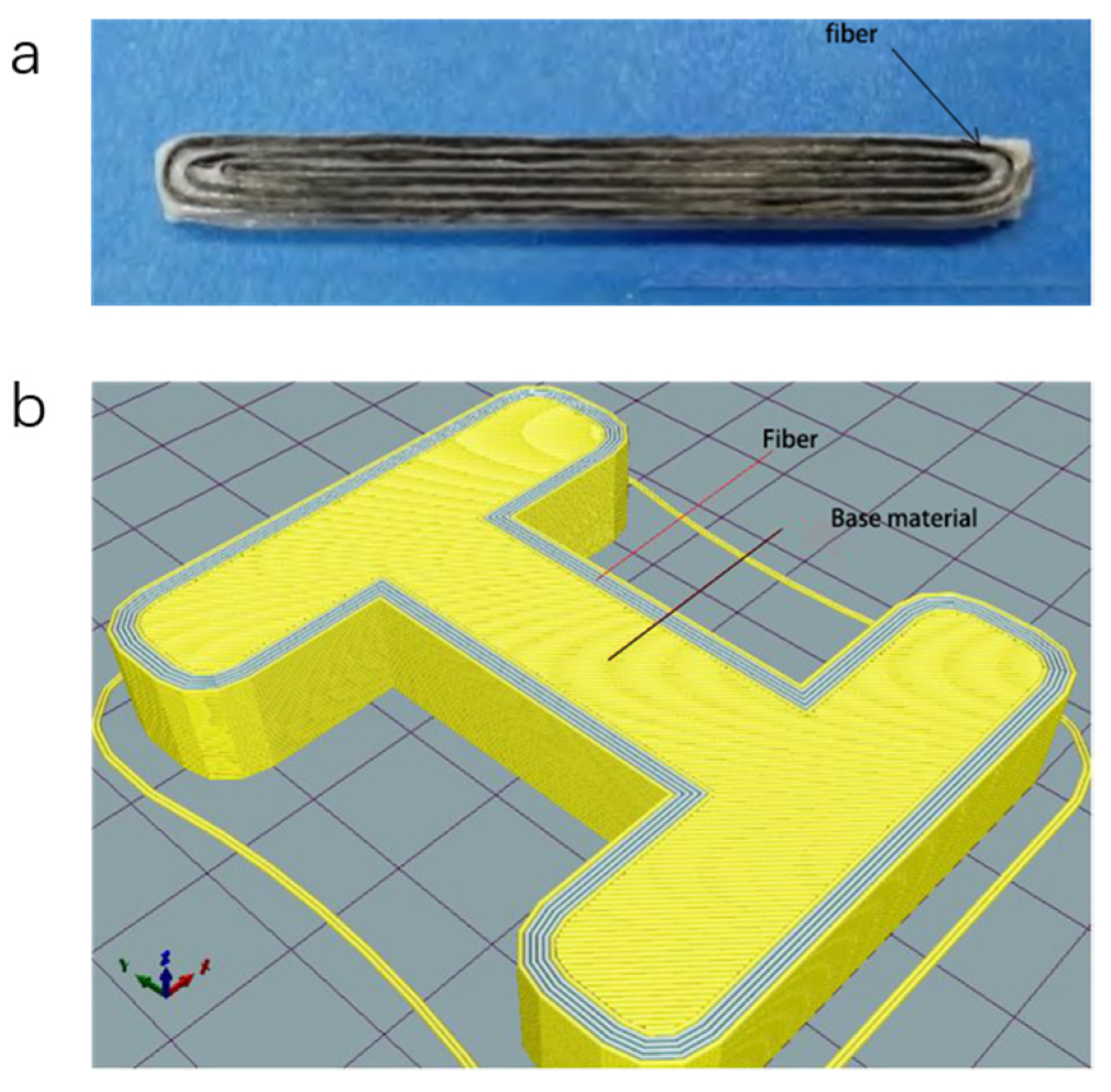
3.2. Verify Printing Effect

The performance of the CFRF printing angle optimization algorithm proposed in this paper depends on the printing reliability of the corner-fitting degree of actual printed specimens (the probability of blockage due to code during printing). The distance d between the point closest to the theoretical vertex in the actual paved path and the theoretical vertex is used to evaluate fitting degree, as shown in Figure 8. The total number of blocked nozzles, blocked pipes, and CFRF broken wires in the printing process was taken to constitute printing reliability. The printing parameters are shown in Table 2.

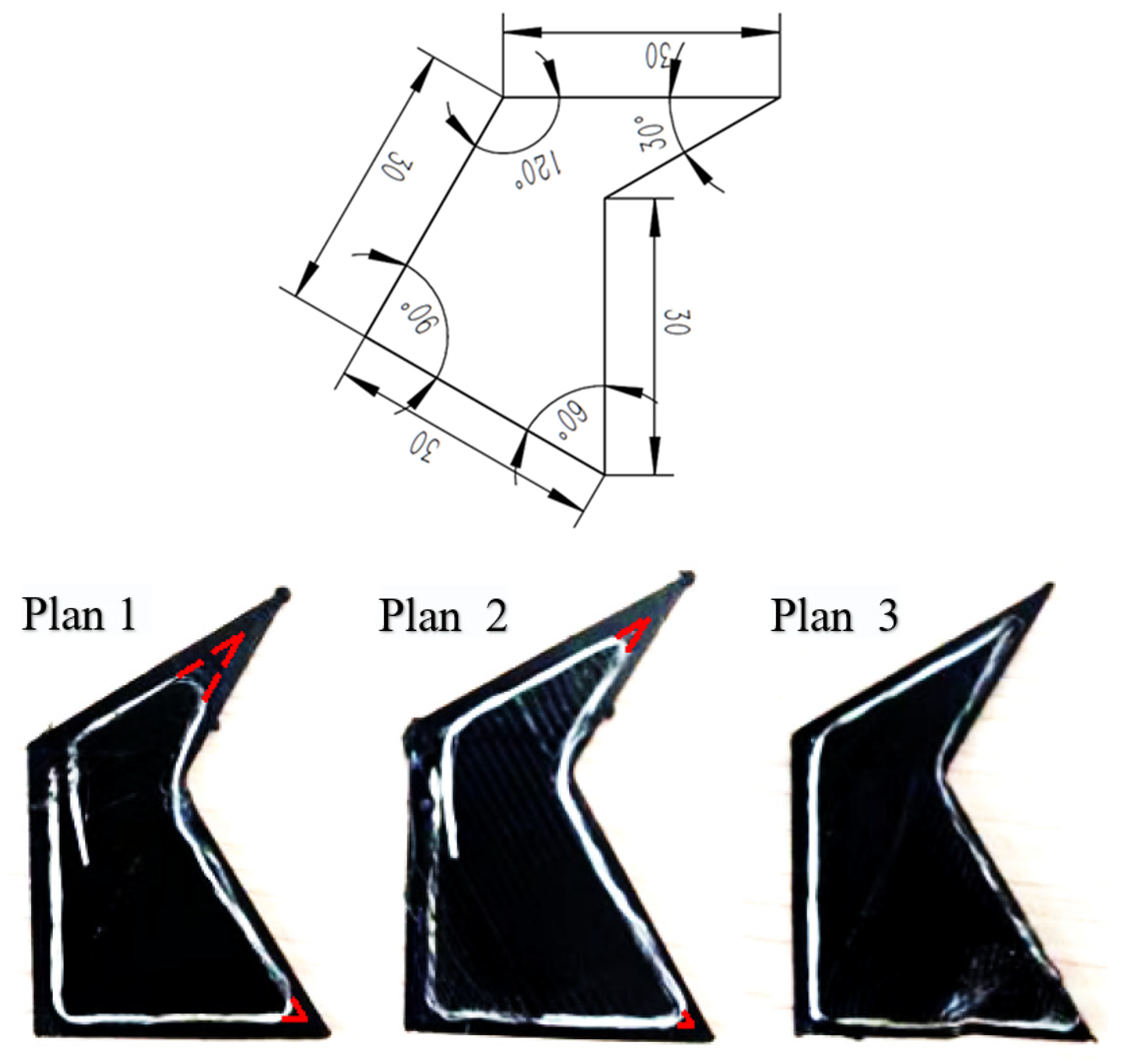
3.2.1. Printing Fit Test

In order to reflect the laying of continuous fibers from different angles, the printing fit was evaluated. Representative print specimens were designed, as shown in Figure 9. The g-code generated by corner optimized slicing software was printed, and the printing results were counted and analyzed. Printing was terminated after completing one CFRF print for observation and analysis.
Table 3 shows the measurement data for CFRF print fit degree at all angles. It can be seen that, with the increase in printing angle, the fitting degree of the actual trajectory and the theoretical trajectory increases gradually. In comparison with the most prominent 30° printing test, the optimized fit was improved by more than 90%, which proved that the optimized scheme greatly improved the fit of fibers when printing sharp angles.

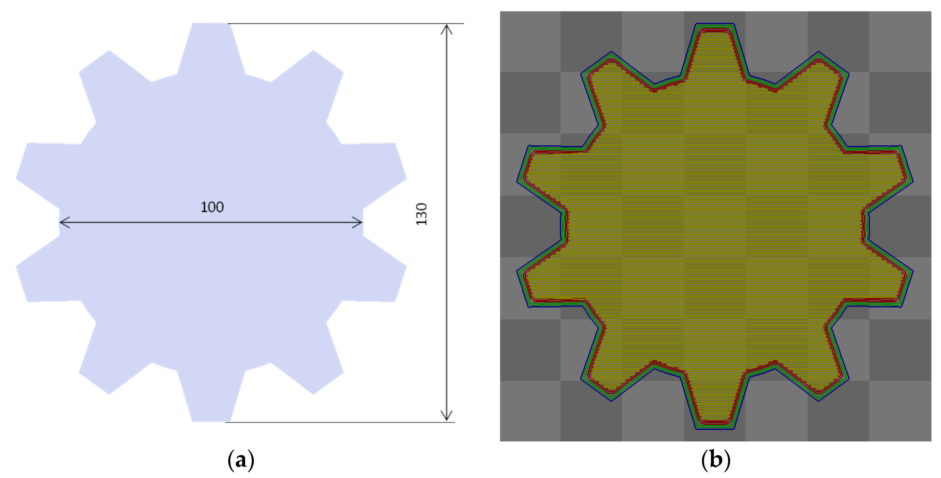
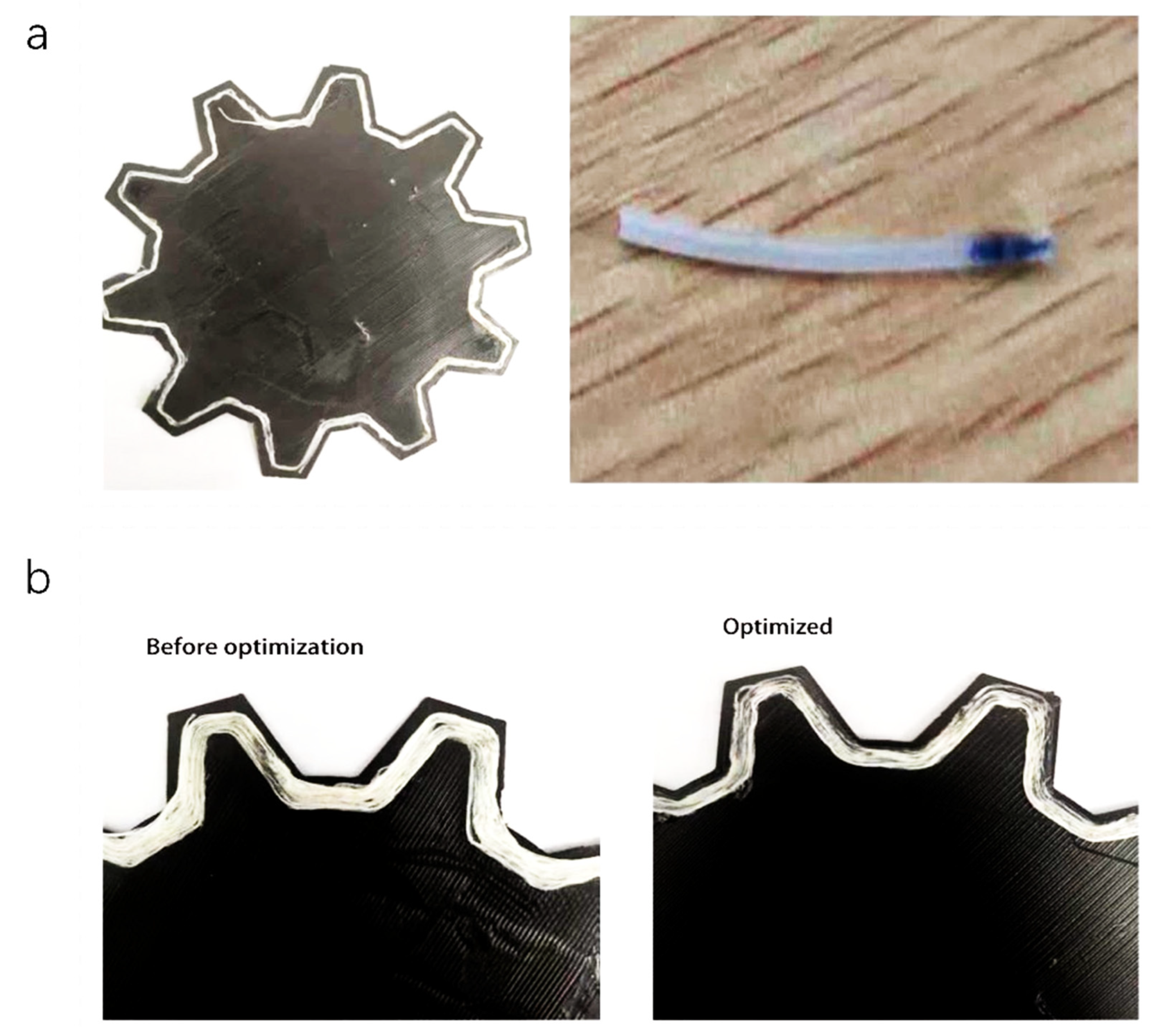
3.2.2. Print Reliability Test

In addition to the print fit, printing reliability is also necessary after corner optimization. A typical print specimen was designed, as shown in Figure 10a, with a thickness of 10 mm and a large volume to ensure that the fiber laid length was large enough. The g-code generated by corner slicing software before and after corner optimization was used for the printing test, and the number of faults, such as blocked nozzles occurring in the printing process, was counted and analyzed. The fiber laying design of the sample is shown in Figure 10b, where the red line indicates the fiber track. In combination with the shape of the specimen, the single-layer fiber laying amount per turn was about 530 mm, and 40 corner layings were completed. Each specimen used one layer of pure PLA substrate at every interval to lay one layer of fiber-reinforcing layer. There were 50 layers in total, of which 24 were fiber-reinforced layers, and the sample size was large enough.
Three groups of controlled experiments were designed. Each layer was offset and printed 3, 6, and 10 times, respectively, and cleaned up after failure, with printing continued from the fault until all the g-codes of the sample were printed. The failures that occurred during printing are shown in Figure 11a. A comparison of laying effects between the two algorithms when the number of fiber-laying turns was 10 is shown in Figure 11b. The optimized laying was more accurate, and the fiber laying before optimization partially overlapped with the external wall.
In this paper, the printing reliability of CFRF is reflected in the number of printing failures. Table 4 shows the statistical data for printing failures. It can be seen that when the number of laying turns of CFRF was 3 in the same layer, there was no blockage of the nozzle before or after the operation of the corner optimization algorithm. As the number of laying turns increased, the g-code before optimization began to fail in the printing process, leading to printing failure. When the number of printing turns was 6 for each fiber layer, two failures occurred in the printing process of CFRF. The total length of CFRF for the 24 layers was 127,200 mm, and there were 960 printing corners when the number of laying turns was 10, with 8 occurrences of nozzle blockage failure. It can be seen that printing length of CFRF is an important parameter affecting the probability of printing failure. With the increase in fiber printing length, the probability of blockage per unit distance increases continuously. However, the g-code generated by the corner optimization algorithm had no nozzle blockage problem under different printing turns of CFRF. So, the printing reliability was greatly improved.

4. Conclusions

This study was based on “independent extrusion” FFF CFRC 3D printing. When the CFRF prints at the corner, the actual laid track is inconsistent with the theoretical track, resulting in printing failure. The reason for this has been analyzed and an effective corner optimization algorithm has been proposed. Through theoretical analysis and practical printing test, the conclusions that can be reached are as follows:
(1)
Through path simulation, the proposed corner optimization algorithm can effectively improve the laying accuracy of CFRF at corners. The printing fault caused by the long-distance printing accumulation error of CFRF was solved in the process of 3D printing.
(2)
According to the analysis of the results of typical specimens with printing fit, with the increase in printing angle, the fit between the actual track and the theoretical track gradually increases. At an angle of 30°, printing fit was increased by more than 90%.
(3)
Based on the analysis of the results for typical test pieces for printing reliability, the corner optimization algorithm can effectively improve the printing reliability of CFRF. When the printing length is 127,200 mm, there are 960 printing corners and the failure rate is 0.

Author Contributions

Conceptualization, J.L. and Y.W.; methodology, Y.K.; software, C.M. All authors have read and agreed to the published version of the manuscript.

Funding

This research received no external funding.

Institutional Review Board Statement

Not applicable.

Informed Consent Statement

Not applicable.

Data Availability Statement

The data are contained within the article.

Conflicts of Interest

The authors declare no conflict of interest.

References

  1. Song, Y.; Li, Y.; Song, W.; Lee, K.Y.; Tagarielli, V.L. Measurements of the mechanical response of unidirectional 3D-printed PLA. Mater. Des. 2017, 123, 154–164. [Google Scholar] [CrossRef]
  2. Hofstatter, T.; Pedersen, D.B.; Tosello, G.; Hansen, H.N. State-of-the-art of fiber-reinforced polymers in additive manufacturing technologies. J. Reinf. Plast. Compos. 2017, 36, 1061–1073. [Google Scholar] [CrossRef] [Green Version]
  3. Melenka, G.W.; Cheung, B.K.O.; Schofield, J.S.; Dawson, M.R.; Carey, J.P. Evaluation and prediction of the tensile properties of continuous fiber-reinforced 3D printed structures. Compos. Struct. 2016, 153, 866–875. [Google Scholar] [CrossRef]
  4. Parandoush, P.; Lin, D. A review on additive manufacturing of polymer-fiber composites. Compos. Struct. 2017, 182, 36–53. [Google Scholar] [CrossRef]
  5. Wang, X.; Jiang, M.; Zhou, Z.; Gou, J.; Hui, D. 3D printing of polymer matrix: A review and prospective. Compos. Part B 2017, 110, 442–458. [Google Scholar] [CrossRef]
  6. Chacón, J.M.; Caminero, M.A.; García-Plaza, E.; Nuñez, P.J. Additive manufacturing of PLA structures using fused deposition modelling: Effect of process parameters on mechanical properties and their optimal selection. Mater. Des. 2017, 124, 143–157. [Google Scholar] [CrossRef]
  7. Rocha, C.R.; Torrado Perez, A.R.; Roberson, D.A.; Shemelya, C.M.; Macdonald, E.; Wicher, R.B. Novel ABS-based binary and temary polymer blends for material extrusion 3D printing. J. Mater. Res. 2014, 29, 1859–1866. [Google Scholar] [CrossRef]
  8. Bhandari, S.; Lopez-Anido, R.A.; Gardner, D.J. Enhancing the interlayer tensile strength of 3D printed short carbon fiber reinforced PETG and PLA composites via annealing. Addit. Manuf. 2019, 30, 100922. [Google Scholar] [CrossRef]
  9. Gu, D.D.; Meiners, W.; Wissenbach, K.; Poprawe, R. Laser additive manufacturing of metallic components: Materials, processes and mechanisms. Int. Mater. Rev. 2012, 57, 133–164. [Google Scholar] [CrossRef]
  10. Bhushan, B.; Caspers, M. An overview of additive manufacturing (3D printing) for microfabrication. Microsyst. Technol. 2017, 23, 1117–1124. [Google Scholar] [CrossRef]
  11. Zhong, W.; Li, F.; Zhang, Z.; Song, L.; Li, Z. Short fiber reinforced composites for fused deposition modeling. Mater. Sci. Eng. 2001, 301, 125–130. [Google Scholar] [CrossRef]
  12. Shofner, M.L.; Lozano, K.; Rodríguez-Macías, F.J.; Barrera, E.V. Nanofiber-reinforced polymers prepared by fused deposition modeling. J. Appl. Polym. Sci. 2003, 89, 3081–3090. [Google Scholar] [CrossRef]
  13. Wang, Y.; Kong, D.; Zhang, Q.; Li, W.; Liu, J. Process Parameters and Mechanical Properties of Continuous Glass Fiber Reinforced Composites-PLA by Fused Deposition Modeling. J. Reinf. Plast. Compos. 2021, 17–18, 686–698. [Google Scholar] [CrossRef]
  14. Chacón, J.M.; Caminero, M.A.; Nuñez, P.J.; García-Plaza, E.; García-Moreno, I.; Reverte, J.M. Additive manufacturing of continuous fibre reinforced thermoplastic composites using fused deposition modelling: Effect of process parameters on mechanical properties. Compos. Sci. Technol. 2019, 181, 107688. [Google Scholar] [CrossRef]
  15. Goh, G.D.; Dikshit, V.; Nagalingam, A.P.; Goh, G.L.; Agarwala, S.; Sing, S.L.; Wei, J.; Yeong, W.Y. Characterization of mechanical properties and fracture mode of additively manufactured carbon fiber and glass fiber reinforced thermoplastics. Mater. Des. 2018, 137, 79–89. [Google Scholar] [CrossRef]
  16. Dickson, A.N.; Ross, K.A.; Dowling, D.P. Additive manufacturing of woven carbon fibre polymer composites. Compos. Struct. 2018, 206, 637–643. [Google Scholar] [CrossRef]
  17. Hou, Z.; Wurikaixi, A. A survey of 3D printing path planning research. Mach. Tool Hydraul. 2016, 44, 179–182. [Google Scholar]
  18. MarkForged. Available online: https://markforged.com/software/ (accessed on 29 June 2022).
  19. Anisoprint. Available online: https://www.imakr.com/anisoprint-3d-printers/2685-anisoprint-composer-a4-110 (accessed on 29 June 2022).
  20. Cheng, Y.; Shi, Y.; Cai, D.; Huang, S. Programming and realization of a compound scanpath in selective laser sintering. Mech. Sci. Technol. 2004, 23, 1072–1075. [Google Scholar]
  21. Zhao, J.; Liu, W.; Xia, R.; Li, L. From Cross Section to Scanning Path in Rapid Prototyping. Int. Conf. Autom. Logist. 2007, 2769–2773. [Google Scholar] [CrossRef] [Green Version]
  22. Bian, H.; Liu, W.; Wang, T.; Shang, X.; Zhang, K. Scanning mode of laser metal deposition shaping. J. Mech. Eng. 2006, 42, 170–175. [Google Scholar] [CrossRef]
  23. Aiyiti, W.; Xiang, L.; Zhang, L.Z.; Chen, R.M. Study on the veritable parameters filling method of plasma arc welding based rapid prototyping. Key Eng. Mater. 2012, 522, 110–116. [Google Scholar] [CrossRef]
  24. Ma, G.; Tan, Y.; Zhang, F.; Zhang, J.; Tan, R.; Huang, J. Research on path jumping processing of long carbon fiber 3D printing. Mach. Des. Res. 2017, 33, 147–150, 164. [Google Scholar] [CrossRef]
  25. Tan, R.; Liu, M.; Zhang, F.; Tan, Y. Continuous path planning algorithm for carbon fiber composite material 3d printing. Mach. Des. Manuf. 2019, 6, 1–4. [Google Scholar] [CrossRef]
  26. Jiang, L. Computer Software Copyright Registration Certificate (2018SR808621); National Copyright Administration of the People’s Republic of China: Beijing, China, 2018. [Google Scholar]
  27. Wang, Y.; Lyu, C.; Zhang, Q.; Li, W.; Liu, J. Preparation and Performance Index Test of Continuous Glass Fiber Reinforced Filament–Polylactic Acid for 3D Printer. J. Phys. Conf. Ser. 2021, 1906, 012053. [Google Scholar] [CrossRef]
Figure 1. (a) The “co-extrusion” printer. (b) The “independent extrusion” printer.
Applsci 12 06687 g001
Figure 2. (a) Self-made 3D printer of CFRC. (b) Working principle of the printing heads. (c) Printing head of CFRF.
Applsci 12 06687 g002aApplsci 12 06687 g002b
Figure 3. (a) Filling mode of the CFRF layer. (b) Contour offset filling method.
Applsci 12 06687 g003
Figure 4. (a) Theoretical and practical printing effects of the contour offset method. (b) Schematic diagram of CFRF printing.
Applsci 12 06687 g004
Figure 5. (a) Schematic diagram of CFRF printing corner trajectory. (b) The corner is obtuse, and the length of BC is long. (c) An example of the error generated in the case of small arcs. (d) The error generated in the case of acute angles.
Applsci 12 06687 g005
Figure 6. (a) Acute angle. (b) Optimize the effect of the acute angle. (c) Schematic diagram of a general corner fiber track.
Applsci 12 06687 g006
Figure 7. Flowchart of the corner optimization algorithm.
Applsci 12 06687 g007
Figure 8. Definition diagram of fit degree.
Applsci 12 06687 g008
Figure 9. Fit evaluation of typical printing specimens. The fitting degree is used to evaluate the effect on printing specimens.
Applsci 12 06687 g009
Figure 10. Reliability assessment of typical printing specimens. (a) Schematic diagram of typical specimens. (b) Fiber laying Trajectory.
Applsci 12 06687 g010
Figure 11. (a) Printing failure. (b) Corner optimization algorithm before and after the printing effect.
Applsci 12 06687 g011
Table 1. Machine parameters of the 3D printer.
NameParameter
Molding materialPLA and ABS, etc.
Reinforced materialCarbon fiber and glass fiber
Molding size (mm)300 × 300 × 300
Number of printing nozzle3
Temperature of printing nozzle (°C)180–400
Temperature of hot bed (°C)30–150
Table 2. The printing parameters.
NameParameter
Printing temperature of matrix material215 °C
Printing temperature of CFRF215 °C
Matrix materialPLA
CFRF materialCGFRF-PLA [27]
Fiber typeGlass fiber
Temperature of hot bed50 °C
Environmental temperature 25 °C
Environmental humidity 30%
Printing speed of matrix material3600 mm/min
Printing speed of CFRF300 mm/min
Printing layer height0.2 mm
Table 3. Printing fit measurement data of CFRF (mm).
Serial Number12345Mean
30°Before optimization3.53.43.43.43.33.4
Optimized<0.1<0.1<0.1<0.1<0.1<0.1
60°Before optimization0.90.90.80.90.80.86
Optimized<0.1<0.1<0.1<0.1<0.1<0.1
90°Before optimization0.50.20.50.30.50.4
Optimized<0.1<0.1<0.1<0.1<0.1<0.1
120°Before optimization0.2<0.10.10.10.2<0.15
Optimized<0.1<0.1<0.1<0.1<0.1<0.1
Table 4. Printing failure statistics for CFRF.
NumberLaying Turns of CFRF for Each LayerLaying Length of CFRF for Each Layer (mm)Total Length of CFRF (mm)Number of Failures after OptimizationNumber of Failures before Optimization
13159038,16000
26318076,32002
3105300127,20008
Publisher’s Note: MDPI stays neutral with regard to jurisdictional claims in published maps and institutional affiliations.

