3.1. Overall Design
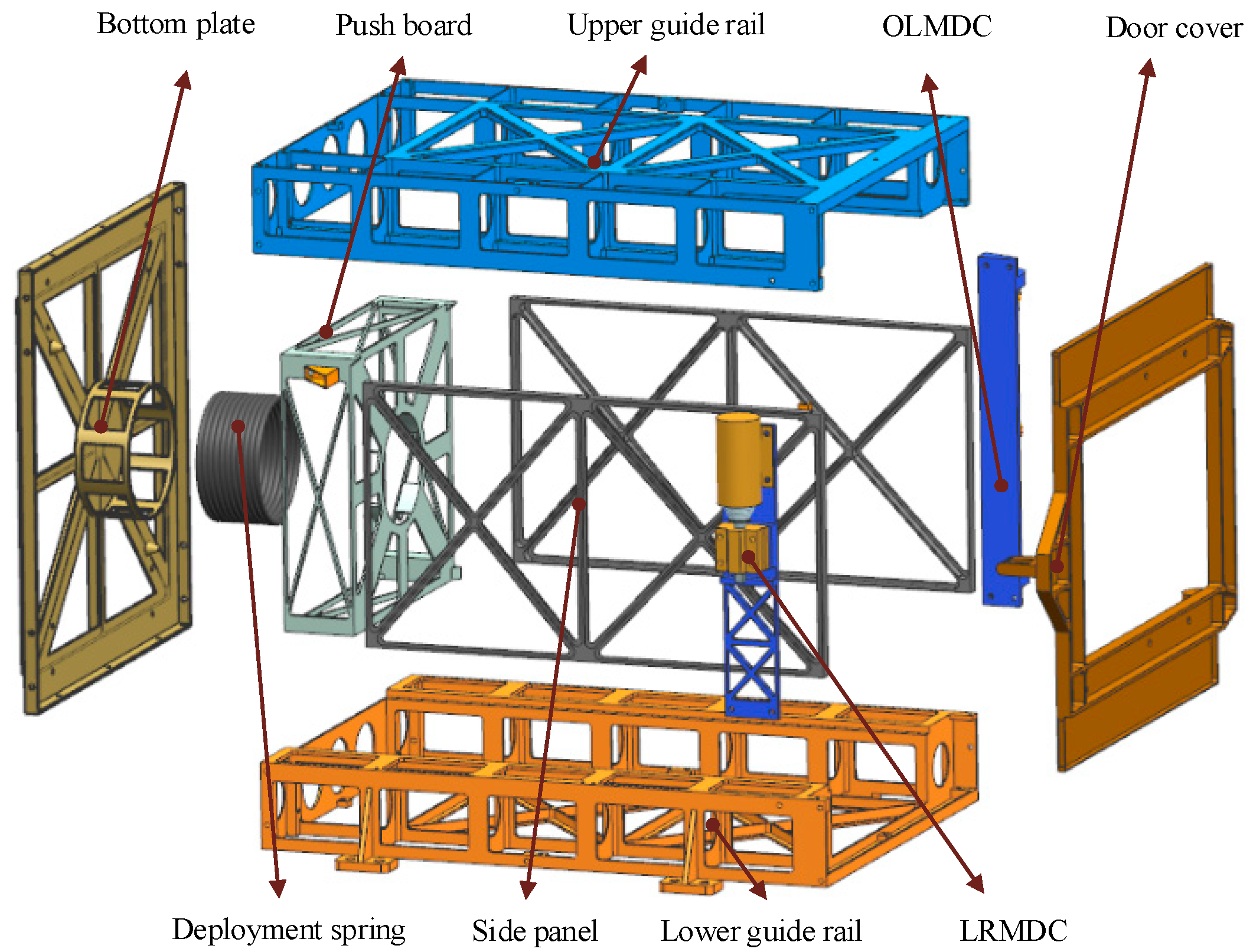
The MF satellite’s separation mechanism is tube-shaped, and the entire structure is box-symmetrical. As illustrated in
Figure 3, the separation mechanism is mainly composed of the bottom plate, deployment spring, push board, upper guide rail, lower guide rail, side panel, door cover, opening and locking module for the door cover (OLMDC), and locking and releasing module for the door cover (LRMDC). The bottom plate, upper guide rail, lower guide rail, side panel, and door cover form the separation mechanism’s primary load-bearing structure. The ejection system is composed of a deployment spring and a push board. Through the use of an electromagnet, the LRMDC mechanism achieves power-on unlocking and power-off locking. The LRMDC mechanism is non-explosive, has no impact, and can be reused on the ground many times. The separation mechanism’s primary load-bearing structure is made of aluminum alloy 2A12 due to its high strength, low density, low cost, and ease of manufacture. The upper and lower guide rails are integrated with the strengthening rib, which is simple to process and assemble and helps maintain the guide rails’ parallelism. The guide rails are hard anodized to prevent cold welding between the satellite’s guide rails and to provide a smooth surface for the MF satellite’s deployment. Due to optimization of the design, the separation mechanism weighs only 5.8 kg. The mass ratio of the satellite to the separation mechanism is only 0.29, significantly less than the mass ratio of the conventional separation mechanism, which significantly reduces launch costs.
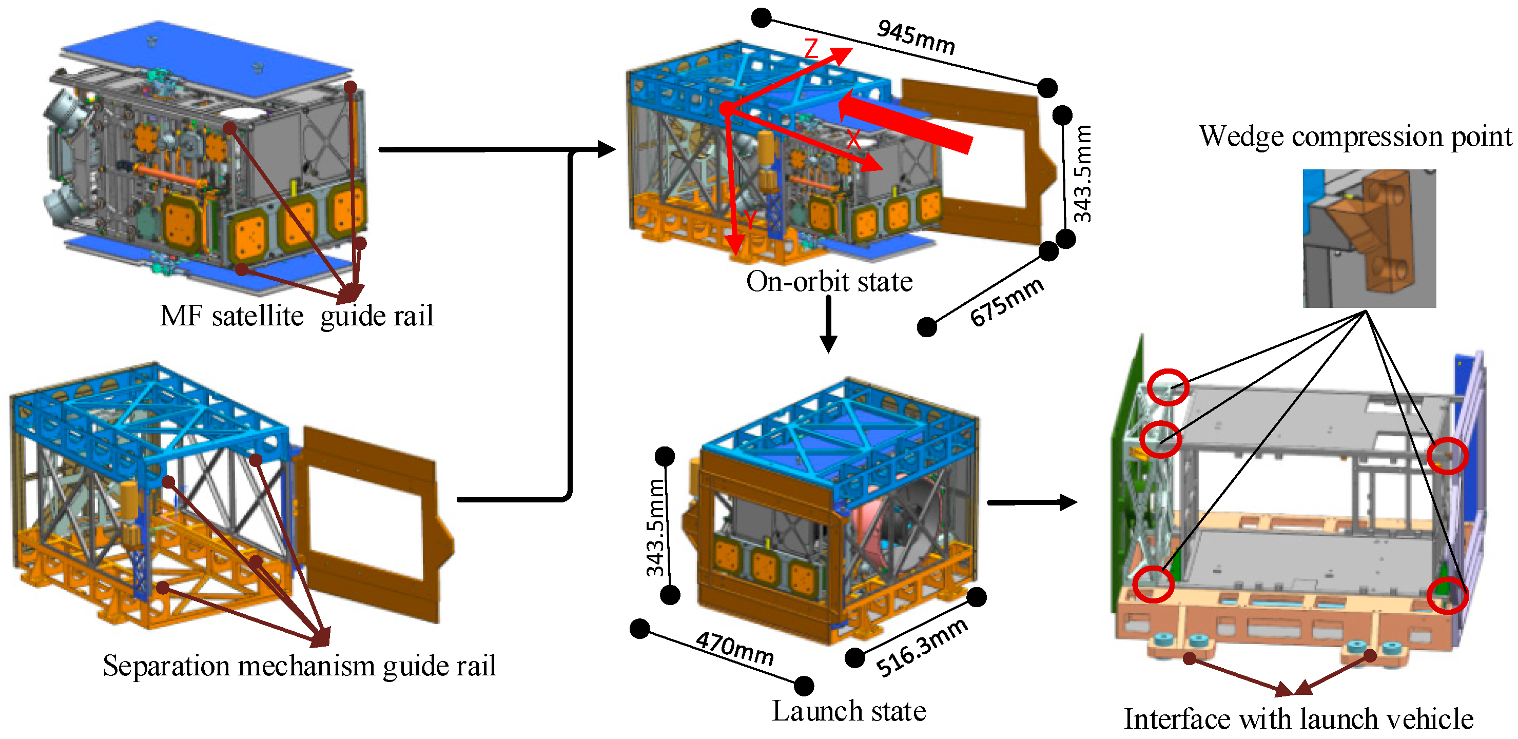
As illustrated in
Figure 4, the outer envelope of the separation mechanism is 343.5 mm × 470 mm × 516.3 mm in the launch state and 343.5 mm × 675 mm × 945 mm in the on-orbit state. Above the guide rails on each side, an additional 50 mm of space is available to accommodate solar panels, a camera hood, and antennas. The length of the guide rail can be adjusted via the satellite’s guide rail. The MF satellite is inserted into the separation mechanism along the guide rail. The rotational hinge joint in the OLMDC can be used to close and open the door cover. The satellite is in contact with the wedge compression points and the four guide rails of the separation mechanism, which restrict the satellite’s vertical movement. The door cover and push board act as horizontal restrictions on the satellite. Eight screws secure the separation mechanism to the carrier launch vehicle. When the MF satellite reaches orbit, the separation mechanism detects the separation signal, the LRMDC releases the door cover, and the OLMDC opens the door cover. Under the action of the deployment spring, the MF satellite will slide out along the guide rail of the separation mechanism. When the door is opened to a certain angle, it is locked in place by the spring positioning pin to prevent it from bouncing back and interfering with the MF satellite in the event of a collision.
3.2. Mechanism Design
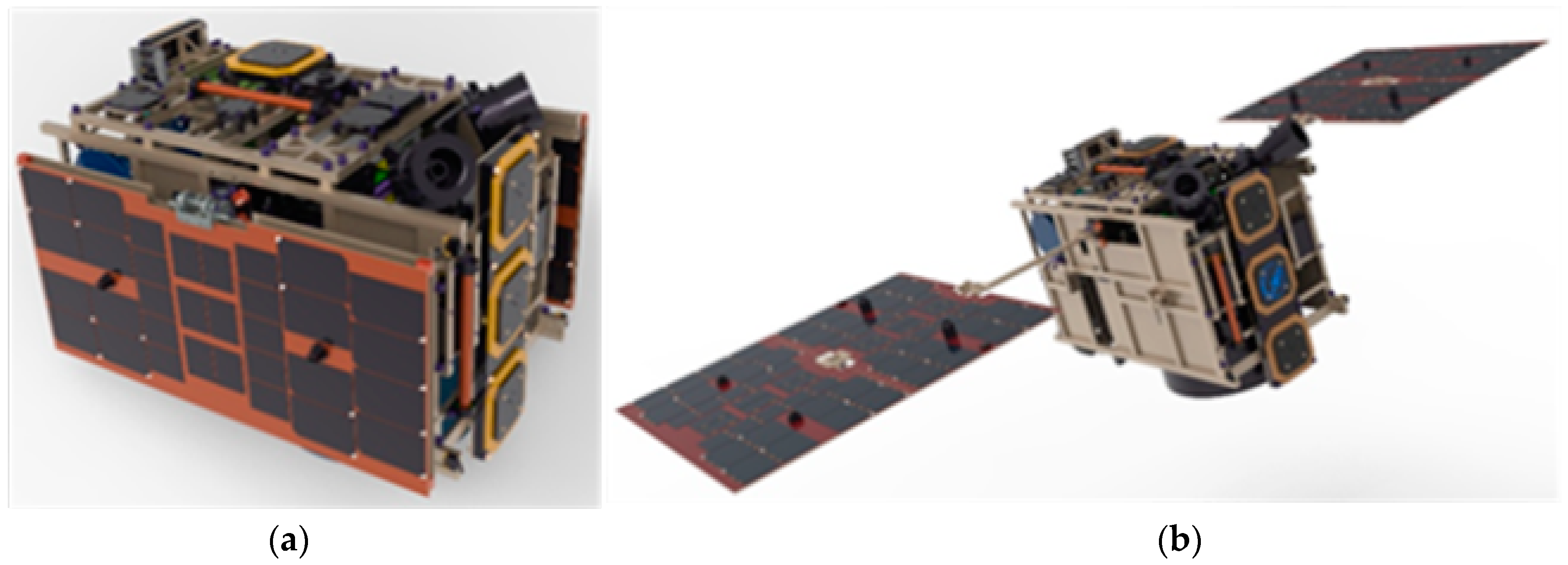
Solar panels are mounted on the MF satellite’s ±Y sides, and the optical camera hood protrudes from the satellite’s surface. Interference collisions between the satellite and the separation mechanism must be avoided during the separation process to avoid damage to the solar panel or the camera. Therefore, a detailed analysis and calculation of the separation mechanism’s motion system are required. The motion system is primarily composed of two components. The ejection system of the satellite comes first, followed by the OLMDC. The following is a detailed design for the two mechanisms mentioned previously.
The deployment spring is the most critical component of the ejection system (a cylindrical compression spring). The deployment spring’s primary function is to release the energy storage once the satellite is on-orbit, allowing the satellite to separate from the launch vehicle. Without considering the elastic damping of the spring and the friction between the MF satellite and the separation mechanism, the relationship is as follows:
where
k—stiffness coefficient of the deployment spring;
—maximum displacement of the deployment spring;
—mass of the MF satellite;
—initial ejecting velocity of the MF satellite.
The deployment spring’s maximum displacement is determined by the length of the separation mechanism’s guide rail, the mass of the MF satellite is constant, and the MF satellite’s initial ejecting velocity is determined by the overall index. To ensure satellite separation reliability in this paper, the spring’s maximum displacement is 420 mm, the MF satellite’s initial ejecting velocity is 0.5 m/s–2 m/s, and the satellite weighs 20 kg. According to Formula (1), the range of the deployment spring’s stiffness coefficient k is 28.3 N/m–453.5 N/m.
The deployment spring’s mean diameter and slenderness ratio should not be too small to maintain the push board’s stability; otherwise, the deployment spring’s axial load will cause lateral bending, resulting in the push board losing stability. The deployment spring’s slenderness ratio must satisfy Formula (2) for the spring to be stable.
where
Given the spring’s maximum displacement of 420 mm and its free height
H0 of approximately 470 mm, the spring’s mean diameter can be calculated to be greater than 88.7 mm using Formula (2). We initially chose a mean diameter of 100 mm for the deployment spring in this paper. At the moment, the deployment spring’s stiffness coefficient, mean diameter, and maximum displacement are known, and the remaining parameters can be calculated using Formula (3). The spring is made of 1Cr18Ni9, which has a shear modulus of 71 GPa. Based on the calculation, a variety of spring parameter groups can be chosen.
where
G—shear modulus of the deployment spring material;
—mean diameter of the deployment spring;
—active coil number of the deployment spring;
—wire diameter of the deployment spring.
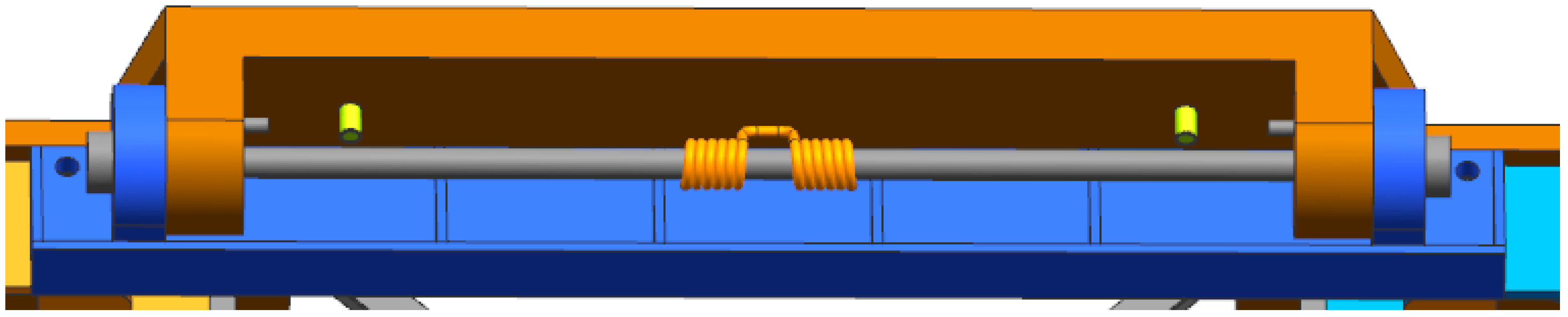
If the door is opened unconstrained, it will collide with the separation mechanism’s side panel and bounce, obstructing the MF satellite’s ejection process and jeopardizing its safety and normal separation. As illustrated in
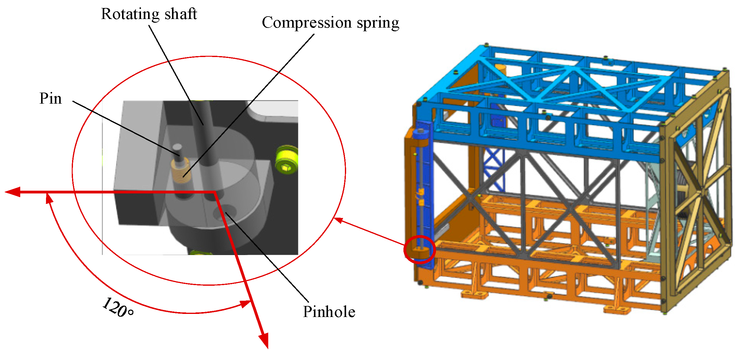
Figure 5, a torsion spring is added to the rotating shaft of the door cover to increase the opening velocity and prevent the door from rebounding. The OLMDC employs a spring positioning pin structure, as illustrated in
Figure 6. After the door cover has been extended to a specified angle, the spring positioning pin structure is used to lock it.
Set the matching gap between the pin and the pinhole to
ε0, the door cover’s rotating angular velocity when it rotates to the locking position to
w0, the distance between the locking hole and the door cover’s rotating shaft to
h0, the weight of the positioning pin to
m0, the compression spring’s stiffness to
k0, the spring’s deformation to
d0, and the pin’s locking stroke to
δ. When the time required to rotate the door cover
ε0/
h0 degrees exceeds the time required to lock the compression spring, the door cover can be successfully locked. The following is advisable according to the dynamic principle:
Formula (4) can be used to determine the elastic coefficient selection range of a compression spring. Appropriate positioning pin spring parameters can be determined by combining the shape and size of the positioning pin and pinhole.


 ,
, 


