Article

Efficiency Analysis of Herringbone Star Gear Train Transmission with Different Load-Sharing Conditions

1
College of Mechanical Engineering, Donghua University, Shanghai 201620, China
2
College of Mechanical Engineering, Suzhou University of Science and Technology, Suzhou 215009, China
*
Author to whom correspondence should be addressed.
Appl. Sci. 2022, 12(12), 5970; https://doi.org/10.3390/app12125970
Submission received: 10 May 2022 / Revised: 1 June 2022 / Accepted: 1 June 2022 / Published: 11 June 2022
(This article belongs to the Topic Dynamical Systems: Theory and Applications)

Abstract

:
A slight improvement in the transmission efficiency of the herringbone star gear train in a GTF has a great impact on the fuel economy of the engine. Here, the influencing factors of gear train efficiency were studied from the perspective of gear train composition, and the efficiency calculation model of the split star gear train, including the load-sharing coefficient, was established. Based on the efficiency calculation model, the mechanical relationship affecting the load distribution of the split star gear train, and the influence of installation error on the power split of the gear train, were studied. The effects of torque and installation error on the load coefficient of the gear train were studied using dynamic analysis software, and the efficiency of the gear train under multiple working conditions was verified and analyzed.

1. Introduction

Fuel economy is an important index of aeroengine performance, so improving the overall efficiency of the engine is a popular research topic of scholars at home and abroad. The herringbone star gear train transmission system is the core component of the Geared Turbofan Engine (GTF), which transmits a large amount of power in a compact structure. A slight improvement in the transmission efficiency of a herringbone star gear train transmission system has a great impact on the fuel economy of the engine.
Many scholars at home and abroad have carried out extensive and in-depth research on the efficiency improvement of the herringbone star gear train transmission system. TALBOT [1] studied the power loss of the gear train through experiments. The results show that the power loss of the gear train can be described by the power and loss transmitted by each branch of the gear train. XU [2] proposed a method to predict the friction loss of the gear pair. The calculation formula of the friction coefficient is based on the new friction coefficient formula model of non-Newtonian thermo-elastohydrodynamic lubrication (EHL), which is obtained by multiple linear regression for EHL prediction under various contact conditions. Based on the virtual power method, CHEN [3] presented and verified the efficiency expression of a composite planetary gear train with power splitting. YANG [4] proposed a new method to calculate the gear train speed ratio, speed, and power based on a hypergraph and matrix. YADA [5] discussed the difference between the Buckingham formula and the Merritt formula in terms of gear meshing efficiency, and analyzed the self-locking phenomenon of planetary gear train. DIAB [6] evaluated various power losses through different models based on the mechanism of power loss of high-speed gears. HU [7] established a reliability model of helical gear meshing efficiency based on the Monte Carlo method, and improved the gear meshing efficiency by optimizing the design parameters. BAO [8] presented an efficiency calculation method of the closed planetary gear train, analyzed the influence of working condition parameters and structural design parameters on efficiency, and obtained the selection principle of structural design parameters of the gear train. XUE [9] analyzed the power flow and transmission efficiency of the composite differential gear train and closed planetary gear train. ZHOU [10] comprehensively considered the friction coefficient under different lubrication conditions, and presented an external meshing friction model and the calculation method of the friction coefficient under this meshing. SONG [11] considered the dynamic meshing efficiency of a herringbone tooth star gear train with a tooth surface spalling defect. YANG [12] solved the complex efficiency problem in the working process of the 2K-H [C] planetary mechanism from the viewpoint of energy, and deduced the efficiency calculation formula. ZHANG [13] considered the time variation in the friction coefficient and found that the increase in tooth surface roughness reduces the transmission error of the gear, but aggravates the vibration in the direction of friction. LAUS [14] proposed a new generic method to determine the efficiency of complex gear trains, and proved that the action responsible for power losses in gearing is a pure torque under certain commonly encountered conditions. ZHAO et al. [15] researched the internal gear pair actual meshing transmission process of an involute cylindrical spur gear, and presented a calculation formula of internal gear pair actual meshing efficiency. REN’s [16] results show that manufacturing error and the float of the component significantly affect the load-sharing characteristics of the herringbone planetary gear train, and that the float of the component can obviously improve the system load sharing performance; as manufacturing errors increase, the system load sharing factor increases. DAI et al. [17] proposed a numerical method to calculate the dynamic mesh forces of planetary gear transmissions. MO et al. [18] proposed a refined mathematical model for the load-sharing coefficient calculation, and the characteristic curve of load sharing was obtained. LIU [19] established a power loss calculation model for a star gear system to analyze the influence of gear parameters on the transmission efficiency.
For the gear train, not only the design parameters, but also the power flow and power distribution, can affect the meshing loss. In this study, based on the power flow of the star gear train, the influence of uneven load distribution on the power loss of the gear train system was examined, a system power loss analysis model integrating the load-sharing condition of the gear train was established, and gear train efficiency analysis under the conditions of an uneven load distribution was undertaken. This research lays a theoretical foundation for the efficiency calculation and improvement of the herringbone gear train.

2. Significance and Methods

For the herringbone gear train working under the conditions of high speed and heavy load, a small increase in efficiency will reduce power loss. The curve of power loss varying with the efficiency of the star gear train is shown in Figure 1. From the figure, the conclusion can be obtained that, when the transmission efficiency increases by only 0.1%, the power loss can be reduced obviously with the increase in efficiency. In the five-way split star gear train, the input power is 20,000 KW and the efficiency of the star gear train is 98.1372% without load-sharing measures. When the efficiency increases by 0.1%, the power loss of the star gear train can be reduced by 5.37% and the value of the power loss reduction can reach 20 KW.
At present, the improvement in transmission efficiency is mainly studied from the perspective of the meshing pair through various optimal designs of the tooth profile. However, the efficiency of the star gear train is also affected by the power split of the gear train. In this study, the main focus was on the influence of the load-sharing performance on the efficiency improvement from the perspective of the gear train. Therefore, the combination of theoretical analysis and case verification was adopted to carry out relevant research. Firstly, from the perspective of gear train unit, the influence model of power splitting on gear train efficiency was established. Then, taking the meshing group as the research object, the meshing force relationship between the meshing pairs of the meshing group was studied, and the influence of errors on the meshing force was analyzed. Finally, the unit efficiency under different load distribution coefficients was verified in the Romax environment, and the load-sharing performance and gearbox vibration were further analyzed.

3. Gear Train Efficiency and Meshing Force Model Analysis

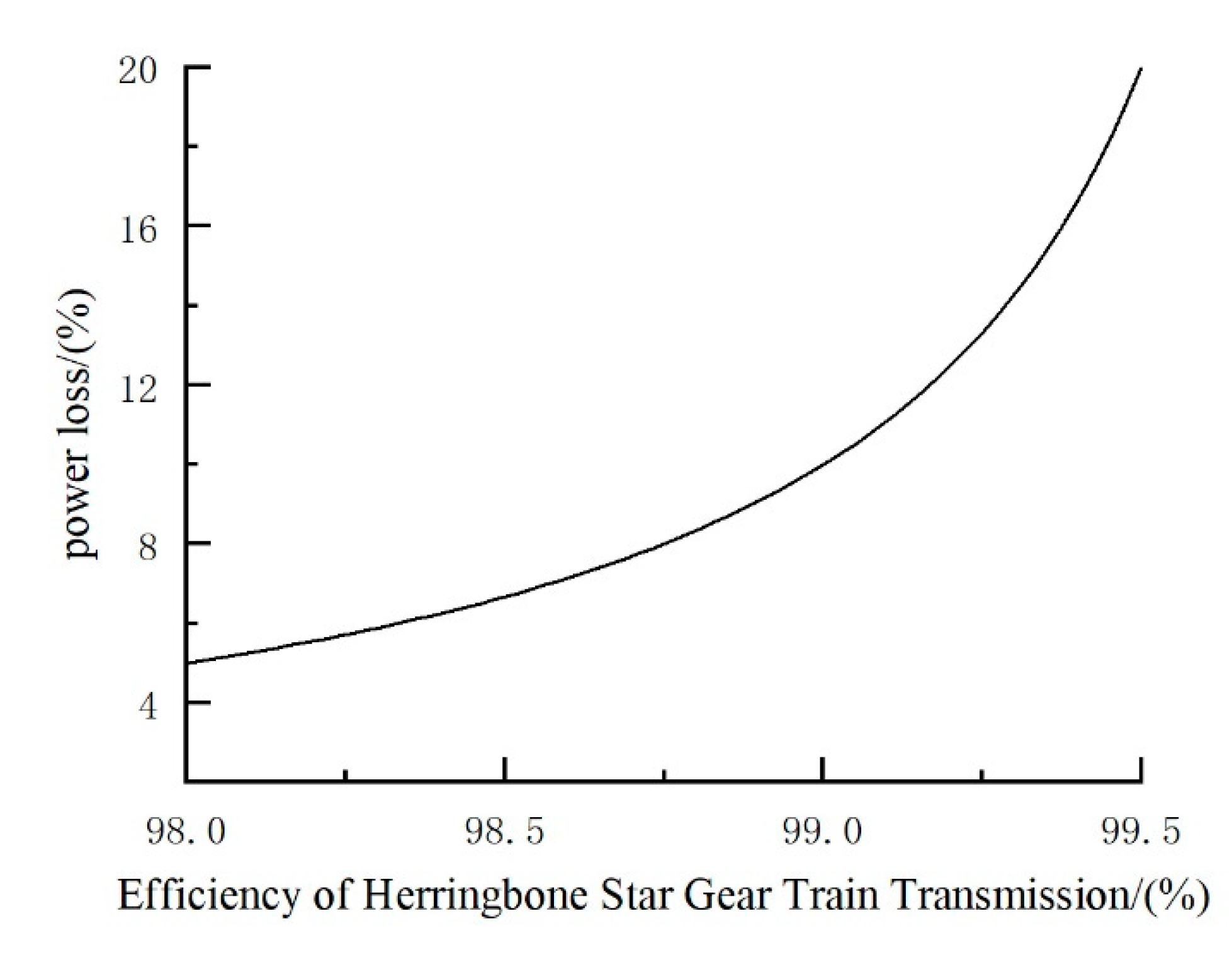
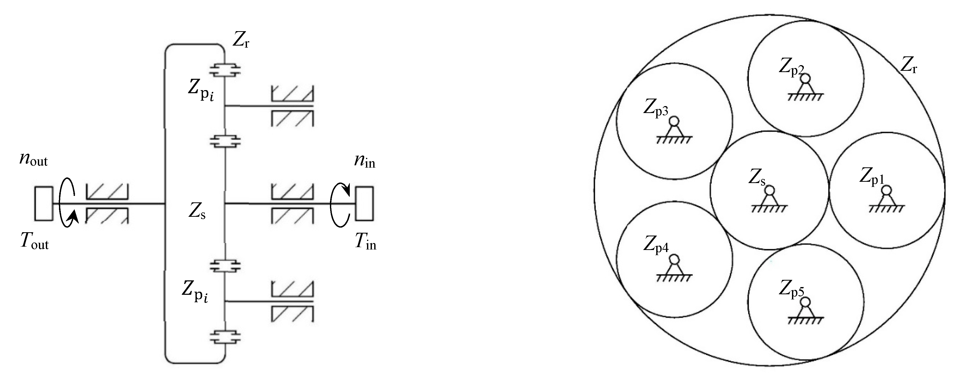
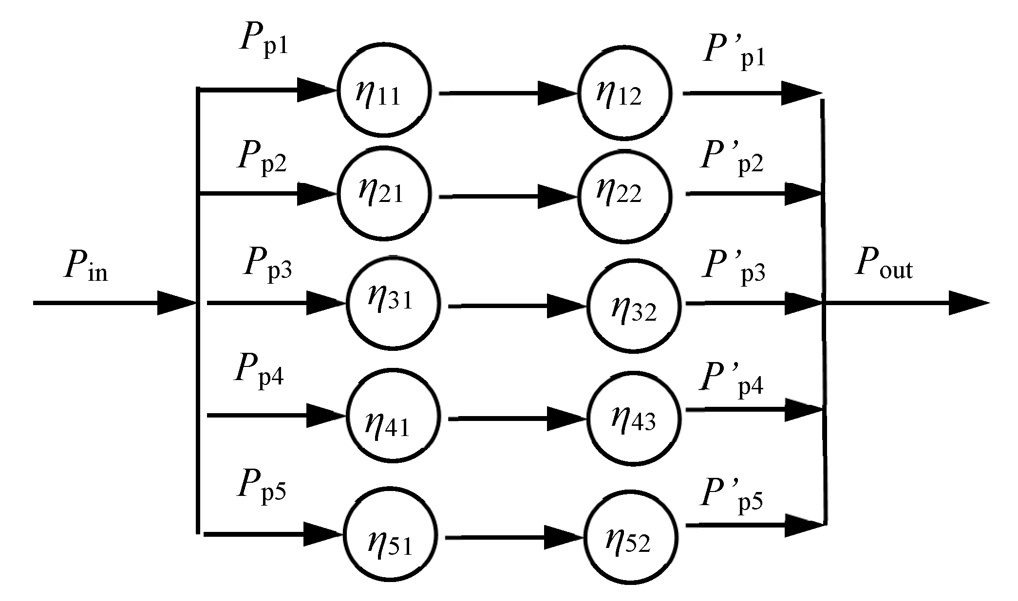
3.1. Power Flow and Efficiency Calculation of Star Gear Train

The mechanism motion diagram of the herringbone tooth star gear train in a GTF is shown in Figure 2. Here, the planet carrier is fixed, and the gear train is essentially a fixed-shaft gear train with power splitting. The total power input by the sun gear is split through the five-way star gear and then output through the internal gear. The design parameters of the star wheel in the herringbone gear train are the same, and the installation position is evenly distributed around the central wheel. However, in actual use, due to the problems of manufacturing accuracy, installation accuracy, load deformation, thermal deformation, etc., the load of each branch is uneven, the power diversion is uneven, and the meshing efficiency of the gear train also changes. For the herringbone tooth star gear train in a GTF with high efficiency requirements, establishing an accurate efficiency calculation model can facilitate further research on the optimization and improvement of efficiency.
Here, the load factor on each branch is set to ξi. (i = 1, 2, …, 5); then:
ξ i = P r e i P a v
where Prei is the power actually allocated on each branch, and Pav is the average power of each branch.
According to the power flow of the star gear train, this star gear train with power splitting is equivalent to a hybrid unit. As shown in Figure 3, the meshing efficiency of each branch is set as ηmi; then, the expression of gear train meshing efficiency ηm is:
η m = 1 n i = 1 n ξ i η m i

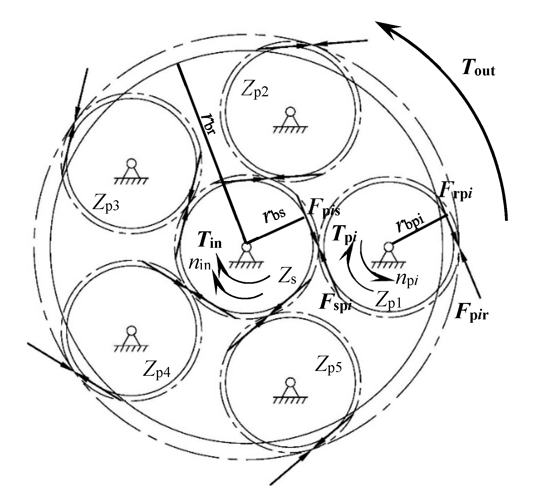
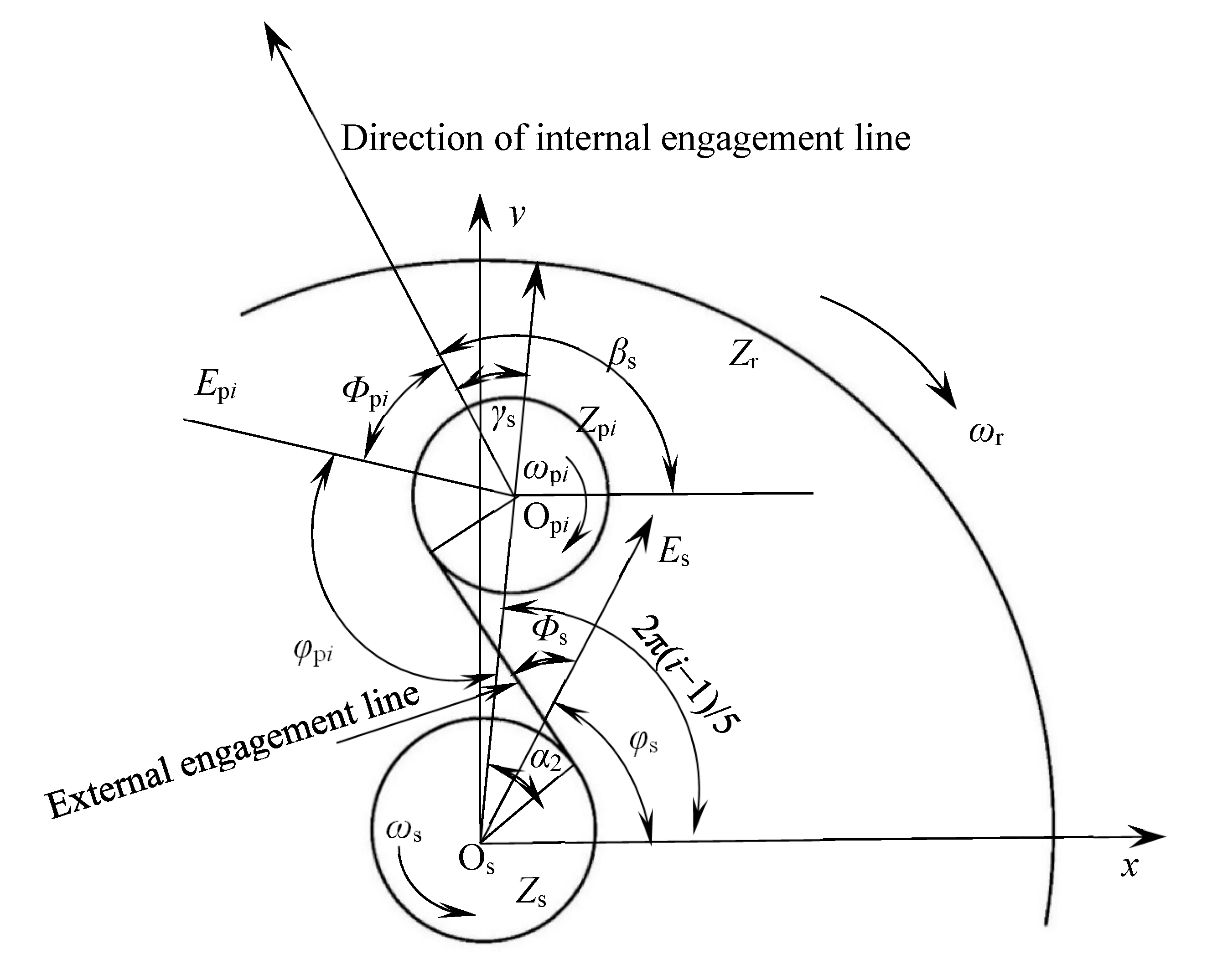
3.2. The Meshing Force Analysis of the Five Star Gears

In order to facilitate the mechanical analysis of the gear train, the center of the sun wheel is taken as the coordinate origin and the orientation of the center of star wheel 1 is taken as the positive direction of the x-axis, and the fixed coordinate system xoy is established, as shown in Figure 4. The five star wheels are evenly arranged, and the sun wheel rotates clockwise. Assuming that the input torque on the sun gear is Tin, the meshing force between the sun gear and the star gear i is Fspi, and the torque generated by the force relative to the center of the sun gear is Tspi. The meshing force between the star gear i and the inner ring gear is Fpir, the torque generated by the force relative to the center of the sun gear is Tpir, and the output torque of the inner ring gear is Tout. rbs, rbpi, and rbr respectively represent the radius of the base circle of the sun gear, the star gear, and the inner ring gear, and Fpis and Frpi are the reactions of Fspi and Fpir, respectively.
Under the ideal condition, the load of the star gear train is evenly distributed, and the meshing force between each star wheel and the sun wheel is equal. At this time, the sun gear is taken as the research object for mechanical analysis, the meshing force on the sun wheel forms a closed regular pentagon, and the meshing force is always tangent to the base circle of the sun wheel. The five meshing forces form a torque equal to the input torque in the opposite direction, which can be expressed as:
r b s i = 1 n F s p i = T in
Similarly, the internal gear is taken as the research object for mechanical analysis, and the meshing force on the inner ring gear is always tangent to the base circle of the inner ring gear. The five meshing forces on the inner ring gear result in a torque equal to the output torque in the opposite direction, which can be expressed as:
d b p i + r b s i = 1 n F p i r = T out
It is worth noting that this closed regular pentagon force model only exists in a completely ideal state. Even if the load-sharing mechanism is adopted, the load cannot be completely evenly distributed. In engineering practice, various methods are adopted to improve the load-sharing performance of the gear train. The purpose is to make the load model of the sun gear infinitely close to a closed regular pentagon.

4. The Effect of Error on the Meshing Force in Star Gear Train

In order to simplify engineering problems, the mechanical model of gear train can be divided into an external meshing pair element and an internal meshing pair element. The external meshing pair element is composed of a sun gear and five star gears, and the internal meshing pair element is composed of five star gears and an inner ring gear. Taking the meshing pair unit as the research object, the error is transformed into the meshing line of each meshing pair equally, and then analyzed from the calculation of the meshing force and the distribution of error on the meshing force.
According to the mechanical model of the meshing pair, the calculation formula of the elastic meshing force between the meshing pairs is shown as follows:
F s p i = K S s p i F r p i = K S r p i
Here, Fspi and Frpi represent the meshing force of external meshing pair and internal meshing pair, respectively, K represents the average meshing stiffness, and Sspi and Srpi represent the relative displacement of the meshing pair on the meshing line considering the error, respectively.
The relative displacement on the meshing line considering the error can be expressed as:
S s p i = w s p i e s p i S r p i = w r p i e r p i
Here, wspi and wrpi respectively represent the ideal displacement of the meshing pair on the meshing line during external meshing and internal meshing, and espi and erpi respectively represent the relative displacement of the meshing line caused by the error during external meshing and internal meshing.

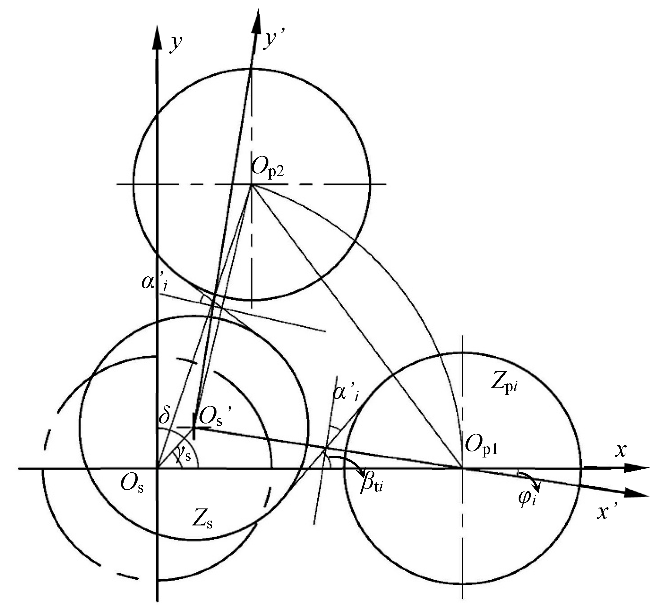
4.1. Ideal Relative Displacement on Meshing Line

The ideal displacement of the gear pair on the meshing line during meshing can be obtained by superimposing the transverse displacement and longitudinal displacement of the gear pair along the meshing line [20]. Here, the relative displacement of the meshing line on the meshing transmission path of a branch is taken as the research object. The equivalent displacement on the meshing line of the meshing pair with the sun wheel and the star wheel can be expressed as:
N n s = n s sin α 1 N τ s = τ s cos α 1 N n p i = n p i sin α 1 N τ p i = τ p i cos α 1
Similarly, the equivalent displacement on the meshing line of meshing gear pair with the star wheel and the inner ring gear during meshing can be expressed as:
N n p i = n p i sin α 2 N τ p i = τ p i cos α 2 N n r = n r sin α 2 N τ r = τ r cos α 2
Here, α1 is the meshing angle of the star wheel and the sun gear, α2 is the meshing angle of the star wheel and the inner ring gear, ns, npi, and nr denote the normal displacement of the sun gear, star gears, and inner gear, and τs, τpi, and τr denote the tangential displacement of the sun gear, star gears, and inner gear, respectively.
To summarize, the relative displacement of the inner and outer meshing pairs on the meshing line without considering the error can be expressed as:
w s p i t = x s x p i + N n s + N τ s + N n p i + N τ p i w r p i t = x r x p i + N n p i + N τ p i + N n r + N τ r
Here, xr, xpi, and xs represent the torsional linear displacement of the inner ring gear, star gears, and sun gear, respectively.

4.2. Relative Displacement of Meshing Line Caused by Error

In order to analyze the difference in the error on the meshing pairs, the coordinate system is established as shown in Figure 5. Taking the center Os of the sun wheel under standard installation as the coordinate origin, the connecting line between the center of the star wheel and the sun gear is the x-axis, and the y-axis meets the Cartesian coordinate system to establish the static coordinate system. Then, the position angle of the five star wheels can be expressed as:
δ = 2 π i 1 5
The coordinates of the actual center of the star wheels can be expressed as:
x i = a cos δ y i = a sin δ
Here, a is the standard center distance.
When the installation error of the sun gear appears in the actual installation, the error causes the relative displacement of the meshing pair on each branch. In order to study the influence of the installation error on the five branches, the actual installation coordinate system is established as xOs′y′. The connection line between the center of the star wheel and the sun gear on the first branch in the actual installation is the x′ axis, as shown in Figure 6. Here, the assembly error of the sun gear is defined as the center deviation distance As and the error position angle γs. Therefore, the coordinates of the actual center of the sun gear are:
x s i = A s cos γ s y s i = A s sin γ s
At this time, the actual center distance between the sun wheel and the star wheels becomes:
a i = x i x s i 2 + ( y i y s i ) 2
The corresponding actual meshing angle can be derived from the following formula:
α i = arccos a cos α a i
The distance between the center of star wheel and the center of the first star wheel can be calculated as:
l i = ( x i a ) 2 + y i 2
Therefore, the position angle of each star wheel under the actual installation coordinate system can be expressed as:
φ i = arccos a 1 2 + a i 2 l i 2 2 a 1 a i
Now, the position angle βti of the meshing line between the sun gear and the star wheel can be expressed as:
β t i = π 2 α i + φ i
Then, the equivalent displacement on the meshing line caused by the installation error of the sun gear can be expressed as:
A ¯ s x = A s x cos β t i A ¯ s y = A s y sin β t i
After superposition of A ¯ s x and A ¯ s y , the equivalent displacement of the installation error on the meshing line can be expressed as:
e s p i = A s cos γ s cos β t i + A s sin γ s sin β t i
Similarly, when the inner ring gear has an installation error, the relative displacement of the installation error on the meshing line can also be expressed as:
e p i r = A r cos γ r cos β t i + A r sin γ r sin β t i
Here, A ¯ r is the installation error of the ring gear, γr is the position angle of the installation error of the ring gear, and βti is the position angle of the meshing line between the star gear and the internal gear.

5. Case Analysis of Load-Sharing Performance

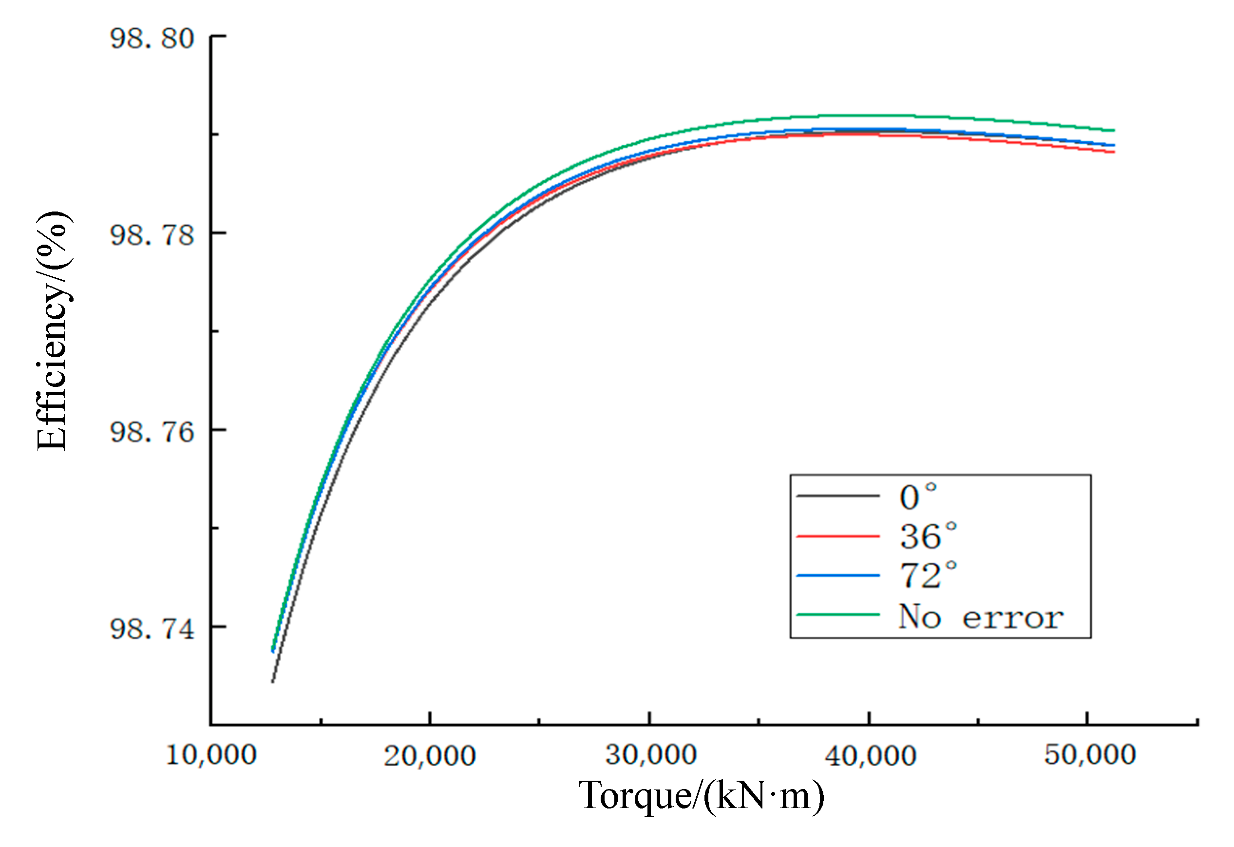
5.1. Case Analysis of Load-Sharing Performance on Efficiency

Based on the basic parameters of the herringbone tooth star gear train in a GTF (as shown in Table 1), the load sharing and efficiency of the gear train were simulated and analyzed in Romax.
The variation curve of load distribution with time for a five way split star gear train under standard installation is shown in Figure 7. The following conclusions can be drawn from the figure: (1) under the standard installation, the load of the five-way split herringbone gear train is also uneven. (2) The load distribution of input torque is determined by the two-stage meshing transmission, which is mainly reflected in the fact that the first- and second-stage transmissions have the same load distribution coefficient. (3) The load distribution curve changes periodically with the meshing position of the herringbone tooth meshing pair.
The variation curve of the load-sharing coefficient of the herringbone tooth star gear train with input power under a five-way shunt is shown in Figure 8. It can be seen from the figure that the load-sharing coefficient of the gear train decreases with the increase in power, and the load-sharing coefficient is about 1.16 at the rated power.
The load coefficient of the gear train with installation error was analyzed, and the conclusion is consistent with that of the theoretical analysis. The details are as follows: (1) In the five-way meteor gear train, the center distance between the sun gear and the inner gear ring under the standard installation is zero. (2) Under non-standard installation, regardless of whether the sun gear or the inner gear ring has installation error, the center distance between the inner gear ring and the sun gear appears. (3) The absolute value and direction angle of the center distance between the inner gear ring and the sun gear due to the installation error have different effects on the load of each shunt branch of the gear train, but they affect the load distribution coefficient of the gear train as a whole. (4) When the size and azimuth of the center distance between the inner gear ring and the sun gear are the same, regardless of whether the center distance comes from the sun gear or the inner gear ring, the influence on the load-sharing coefficient of the whole gear train is basically the same, as shown in Table 2. (5) The center distance error mainly affects the branch load coefficient on the direction angle of the center distance. In engineering application, this point may be used to reduce the load coefficient of the gear train by setting an appropriate value for the center distance error.
Considering the load coefficient, the efficiency of the star gear train was analyzed. The efficiency curve varying with torque is shown in Figure 9. From the efficiency curve, the uneven distribution of five shunt loads will reduce the efficiency of the gear train, and the greater the load-sharing coefficient, the lower the efficiency. Without load-sharing measures, the load coefficient of the star gear train with a five-way power split is about 1.12, which is slightly lower than the efficiency of theoretical load sharing. If the load-sharing coefficient increases further due to various errors, it will not only affect the efficiency of the system, but also cause insufficient bearing capacity of a gear in the gear train or affect the service life of parts. Therefore, improving the load-sharing performance of the gear train and limiting its load-sharing coefficient to a certain range is an important premise to ensure the high-efficiency transmission of the gear train.

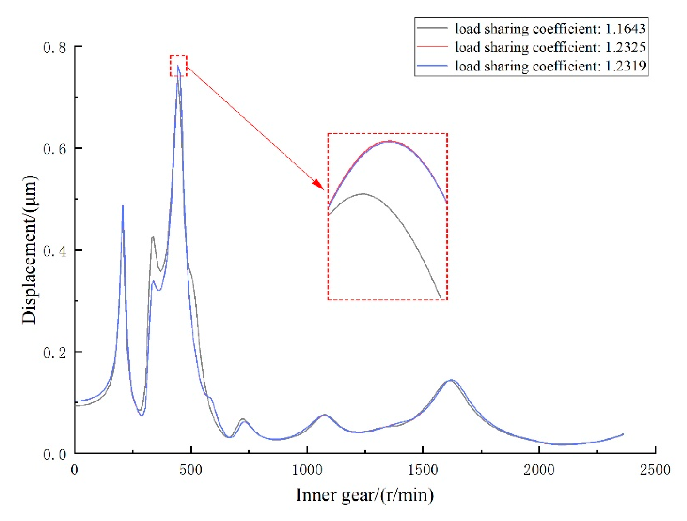
5.2. Influence of Load-Sharing Performance on Vibration of Gearbox

Considering the load-sharing performance of the star gearbox, the vibration of the star gearbox under different load coefficients was analyzed. The inner gear was taken as the research object, and the vector displacement of the internal gear ring’s barycenter, indicating the gear vibration varying with the speed, is shown in Figure 10. The vector displacement of the peaks in the curve increased by 2.92% and 3.05%, respectively, when the load coefficients were 1.2319 and 1.2325, compared with 1.1643. The conclusion is that the vibration of the gearbox is increased due to the uneven distribution of the five shunt loads. Therefore, improving the load-sharing performance of the gear train can not only improve the efficiency, but also reduce the vibration of the gearbox.

6. Conclusions

The efficiency analysis of a star gear train under multiple working conditions was carried out, including complete uniform load distribution under ideal conditions, actual load distribution without any load-sharing measures, and load distribution with errors. The results show that the unbalanced power split caused by load distribution significantly affects the efficiency of the star gear train and the vibration of the gearbox. The results are as follows:
(1)
The total efficiency of the star gear train can be regarded as a parallel unit composed of multiple shunt branches, which can be improved by improving the efficiency of the shunt branch and adjusting the load coefficient of the branch.
(2)
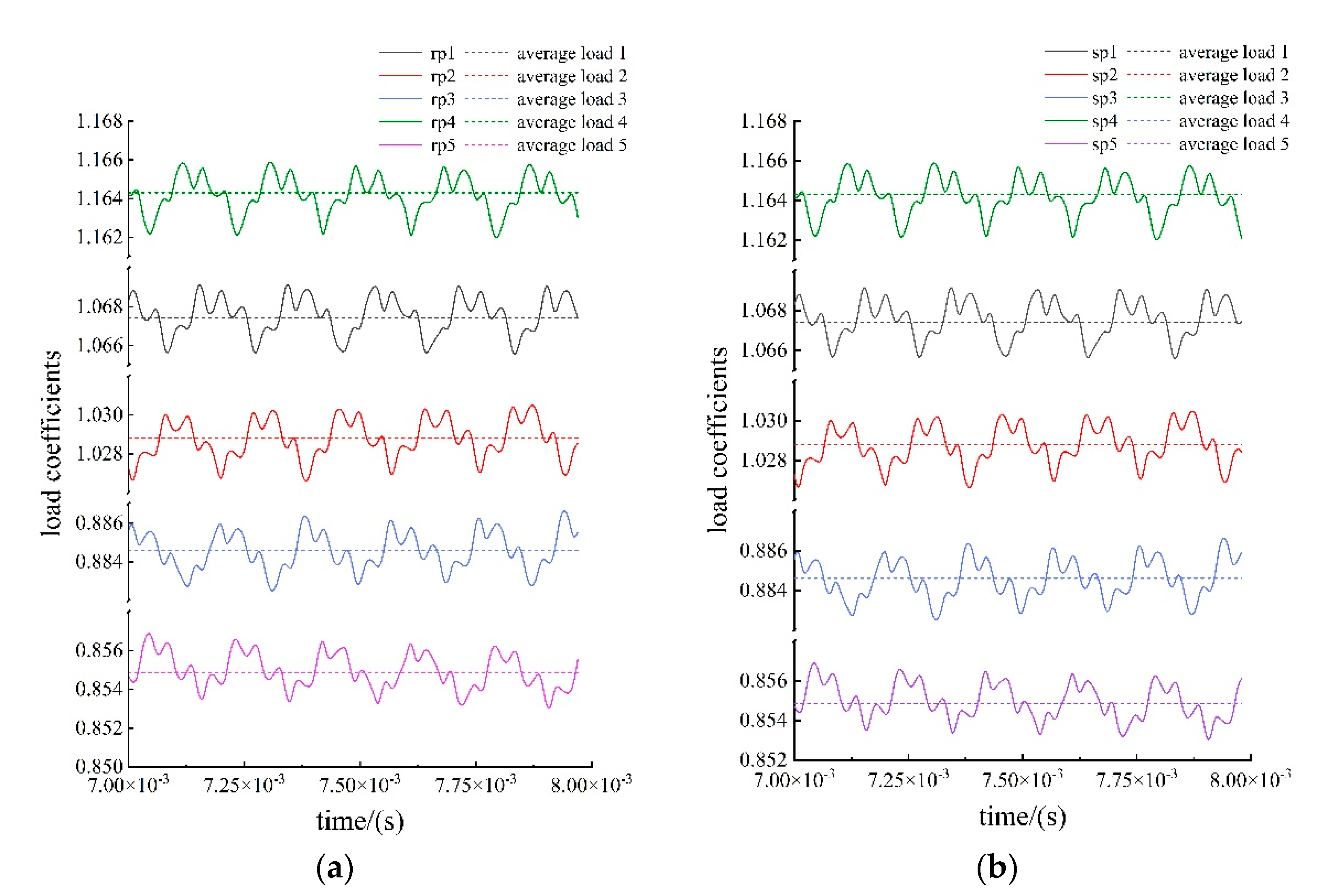
The adjustment of the load coefficient affecting gear train efficiency can be realized by adjusting the center distance and center distance azimuth between the sun gear and the inner gear ring. Regardless of the change in the load coefficient between the shunt branches, the sum of the meshing forces of the five meshing pairs in the inner or outer meshing group is fixed. Ideally, the five meshing forces form a regular pentagon.
(3)
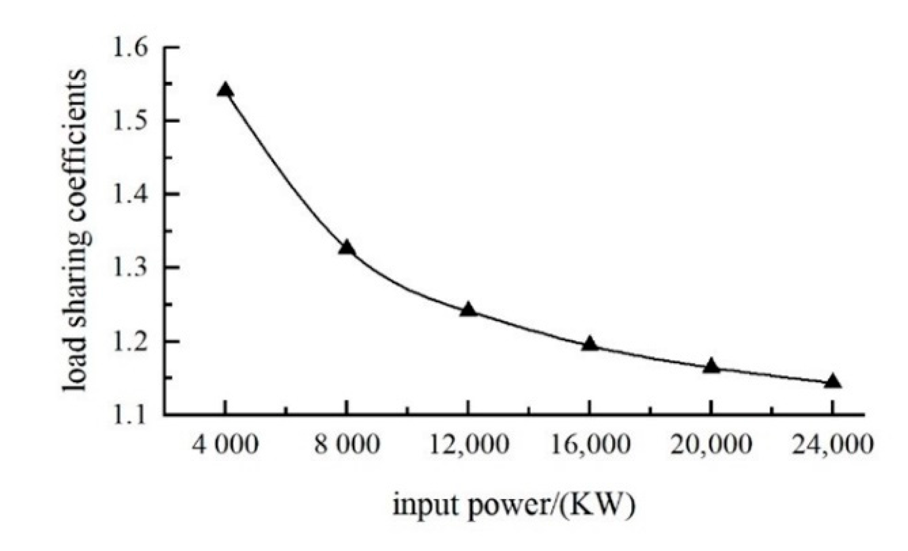
The load-sharing coefficient of the gear train decreases with the increase in power. Without load-sharing measures, the load coefficient of the star gear train with five-way power splitting is about 1.16, which is slightly lower than the efficiency of theoretical load sharing.
(4)
The uneven distribution of five shunt loads not only reduces the efficiency of the gear train, but also increases the vibration of the gearbox. The greater the load-sharing coefficient, the lower the efficiency and the larger the vibration.

Author Contributions

Conceptualization, S.W.; Formal analysis, D.L. (Dongliang Li); Investigation, Y.Y.; Writing—original draft, D.L. (Dong Li). All authors have read and agreed to the published version of the manuscript.

Funding

This work is financially supported by the National Key R&D Program of China (No. 2018YFB2001502).

Institutional Review Board Statement

Not applicable.

Informed Consent Statement

Not applicable.

Data Availability Statement

The data presented in this study are available upon request from the corresponding author.

Conflicts of Interest

The authors declare no conflict of interest.

References

  1. Talbot, D.C.; Kahraman, A.; Singh, A. An Experimental Investigation of the Efficiency of Planetary Gear Sets. In Proceedings of the ASME 2011 International Design Engineering Technical Conferences and Computers and Information in Engineering Conference, Washington, DC, USA, 28–31 August 2011. [Google Scholar]
  2. Xu, H. Development of a Generalized Mechanical Efficiency Prediction Methodology for Gear Pairs. Ph.D. Thesis, The Ohio State University, Columbus, OH, USA, 2005. [Google Scholar]
  3. Chen, C. Power flow and efficiency analysis of epicyclic gear transmission with split power. Mech. Mach. Theory 2013, 59, 96–106. [Google Scholar] [CrossRef]
  4. Yang, F.; Feng, J.; Zhang, H. Power flow and efficiency analysis of multi-flow planetary gear trains. Mech. Mach. Theory 2015, 92, 86–99. [Google Scholar] [CrossRef]
  5. Yada, T. Review of gear efficiency equation and force treatment. JSME Int. J. Ser. C 1997, 40, 1–8. [Google Scholar] [CrossRef]
  6. Diab, Y.; Ville, F.; Velex, P. Investigations on power losses in high-speed gears. Proc. Inst. Mech. Eng. Part J J. Eng. Tribol. 2006, 220, 191–198. [Google Scholar] [CrossRef]
  7. Hu, M.; Hu, Y.; Li, J.; Liu, W. Reliability Analysis on Random Meshing Efficiency of Helical Gear based on Monte Carlo Method. J. Mech. Transm. 2021, 45, 5. [Google Scholar]
  8. Bao, H.; Li, L.; Jin, G.; Liu, F. Calculation and Analysis of Encased Planetary Train Efficiency. Mach. Build. Autom. 2019, 48, 5. [Google Scholar]
  9. Xue, H.; Liu, G.; Yang, X. Simplified Method for the Power Flow and Transmission Efficiency Analysis of Epicyclic Gear Train. J. Mech. Transm. 2017, 41, 43–48. [Google Scholar]
  10. Zhou, C.; Tang, J.; Zhong, Z.; Wu, C. Studies on the Calculation of Teeth Surface Friction Coefficients in Gear Drive. Lubr. Eng. 2006, 182, 185–191. [Google Scholar]
  11. Song, C. Dynamic Characteristic and Meshing Efficiency Analysis of Double Helical Star Gear System with Tooth Spalling Defect. Master’s Thesis, Chongqing University, Chongqing, China, 2020. [Google Scholar]
  12. Yang, Z.; Chen, M. Mesh Efficiency of the Gears in 2K-H(C) Type. J. China Text. Univ. 1997, 23, 82–87. [Google Scholar]
  13. Zhang, J.; Chen, B.; Zhang, C.; Wu, C. Dynamic analysis for spur gears considering friction effect. J. Vib. Shock 2012, 31, 126–132. [Google Scholar]
  14. Laus, L.P.; Simas, H.; Martins, D. Efficiency of gear trains determined using graph and screw theories. Mech. Mach. Theory 2012, 52, 296–325. [Google Scholar] [CrossRef]
  15. Zhao, N.; Wei, F.; Hui, G.; Kang, S. The effect on internal gear-pair actual meshing by the basic parameters of gear. Mod. Manuf. Eng. 2009, 8, 71–73. [Google Scholar]
  16. Ren, F.; Qin, D.; Wu, X. Load sharing performances of herringbone planetary gears considering manufacturing errors. J. Cent. South Univ. (Sci. Technol.) 2016, 258, 474–481. [Google Scholar]
  17. Dai, H.; Chen, F.; Xun, C.; Long, C. Numerical calculation and experimental measurement for gear mesh force of planetary gear transmissions. Mech. Syst. Signal Process. 2022, 162, 108085. [Google Scholar] [CrossRef]
  18. Mo, S.; Zhang, Y.D.; Wu, Q. Research on multi split load sharing mechanism of GTF engine star drive system. J. Aeronaut. Dyn. 2016, 31, 763–768. [Google Scholar]
  19. Liu, W. Research on Dynamic Efficiency of Double Helical Star Gear Trains. Master’s Thesis, Nanjing University of Aeronautics and Astronautics, Nanjing, China, 2017. [Google Scholar]
  20. Zhu, Z. Research on Load Sharing and Dynamics Characteristics of Encased Differential Herringbone Train. Ph.D. Thesis, Nanjing University of Aeronautics and Astronautics, Nanjing, China, 2013. [Google Scholar]
Figure 1. Power loss ratio at different efficiencies.
Applsci 12 05970 g001
Figure 2. The mechanism motion diagram of herringbone tooth star gear train.
Applsci 12 05970 g002
Figure 3. Power splitting diagram of the star gear train.
Applsci 12 05970 g003
Figure 4. Force analysis of gear trains.
Applsci 12 05970 g004
Figure 5. Diagram of gear meshing position relationship.
Applsci 12 05970 g005
Figure 6. Equivalent engagement error of the sun gear.
Applsci 12 05970 g006
Figure 7. Load coefficient of the herringbone gear train under standard installation: (a) internal contact, (b) external contact.
Applsci 12 05970 g007
Figure 8. The load-sharing coefficient varying with the input power of herringbone star gear system.
Applsci 12 05970 g008
Figure 9. Influence of load-sharing coefficient on gear train efficiency.
Applsci 12 05970 g009
Figure 10. Vector displacement curve diagram of inner gear.
Applsci 12 05970 g010
Table 1. Basic parameters of herringbone tooth star gear train in a GTF.
ParametersSun GearStar GearAnnular Gear
Tooth number4342127
Tooth width (mm)60 × 259 × 257 × 2
Rotation speed (r/min)7463−7640.69−2526.84
Power (KW) 20,000
Normal module (mm) 3.5
Normal pressure angle (°) 22.5
Spiral angle (°) 26.969
Table 2. Sun gear–planet gear external meshing load coefficient (installation error).
Standard InstallationInstallation Error
with the Sun Gear
Installation Error
with the Inner Gear
load coefficientInternalExternalInternalExternalInternalExternal
1.1643071.1643071.2319181.2319301.2325451.232509
Publisher’s Note: MDPI stays neutral with regard to jurisdictional claims in published maps and institutional affiliations.

