
Knowledge-Based Automated Mechanical Design of a Robot Manipulator


Abstract
:1. Introduction
2. Materials and Methods
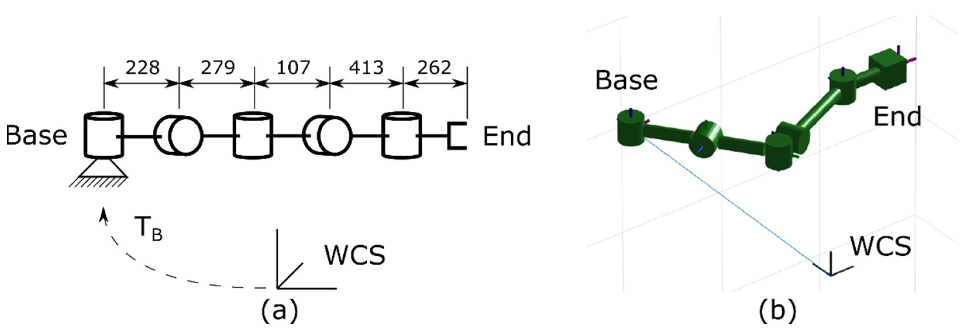
2.1. Kinematic Synthesis through Optimization
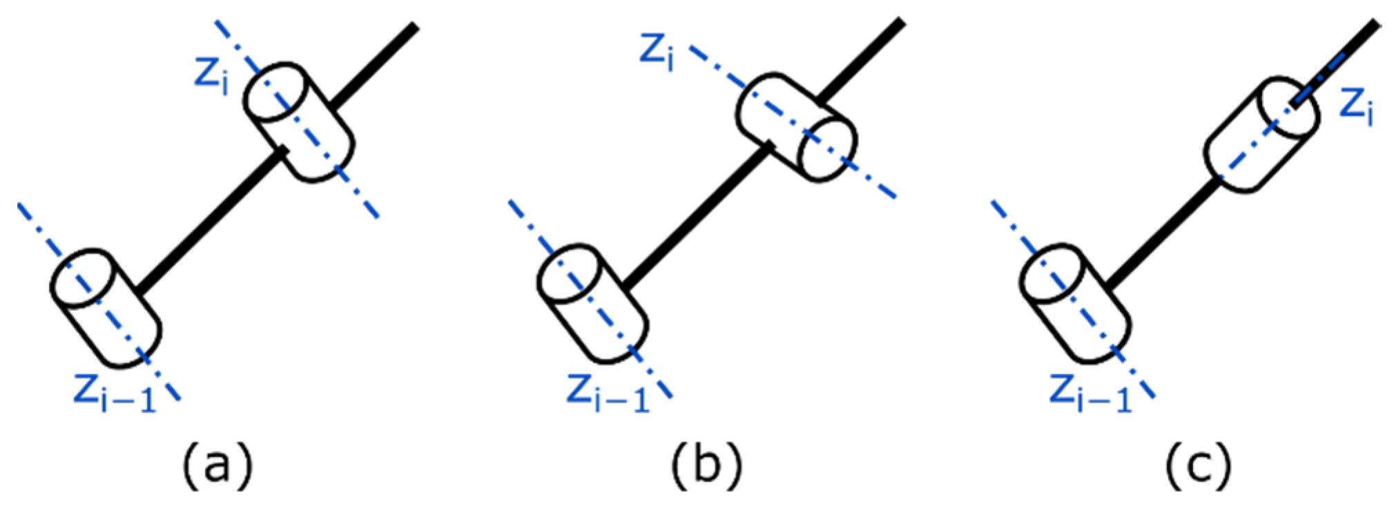
2.1.1. Robot Genotype Encoding
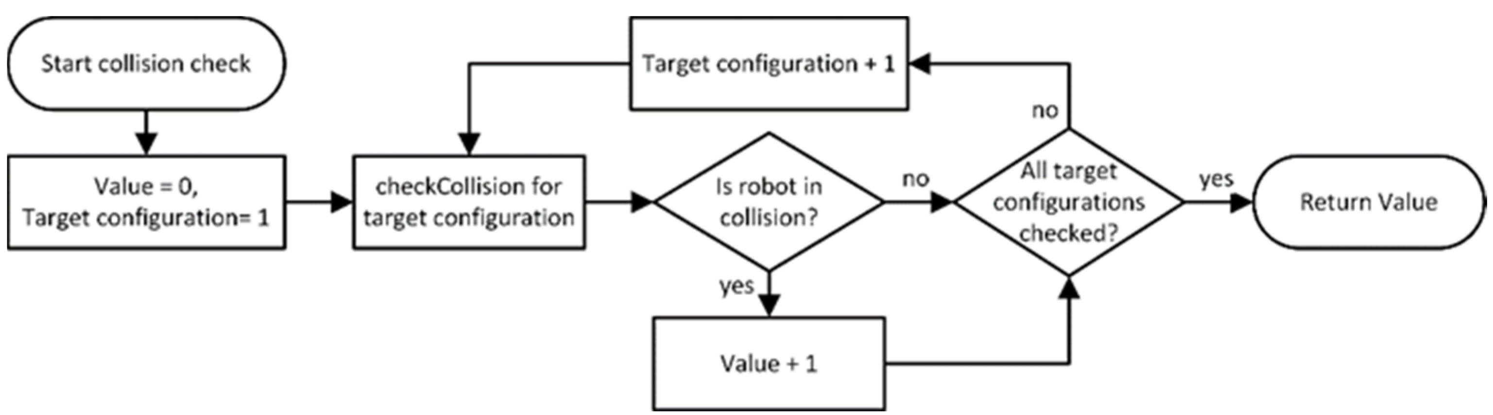
2.1.2. Evaluation
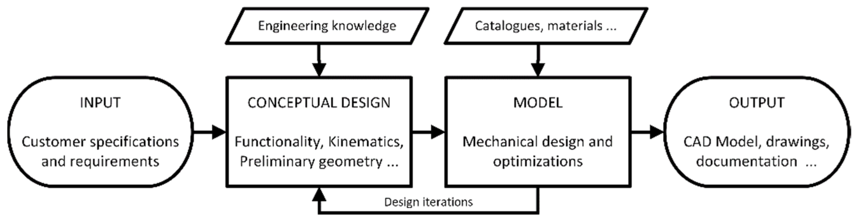
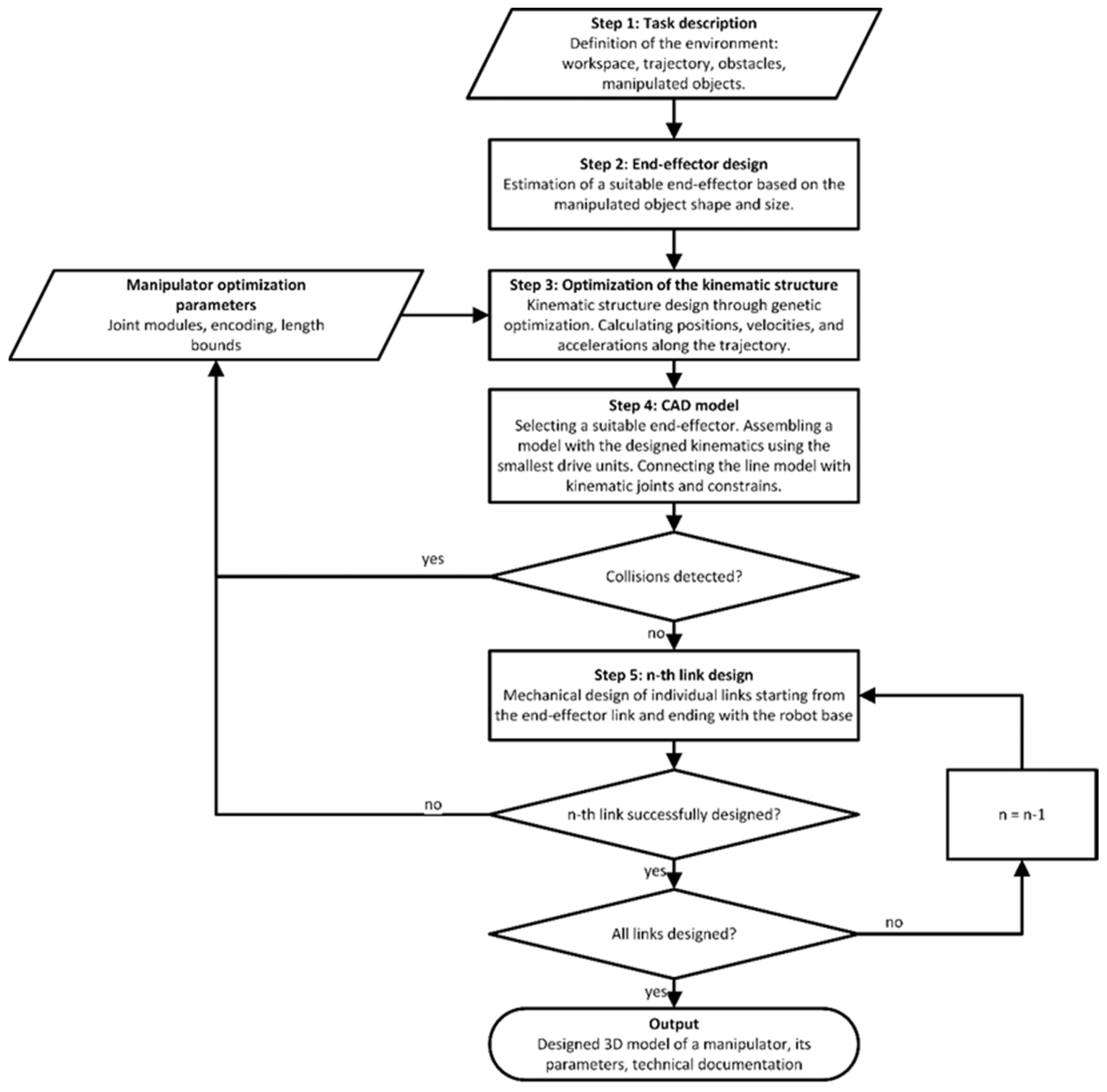
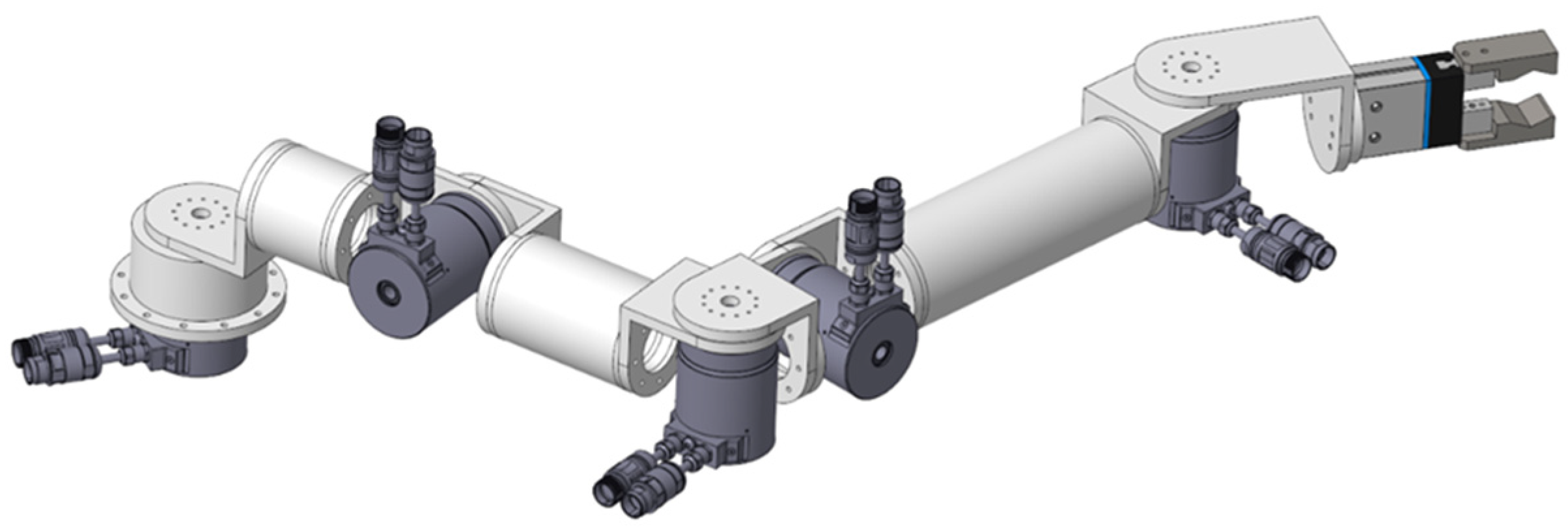
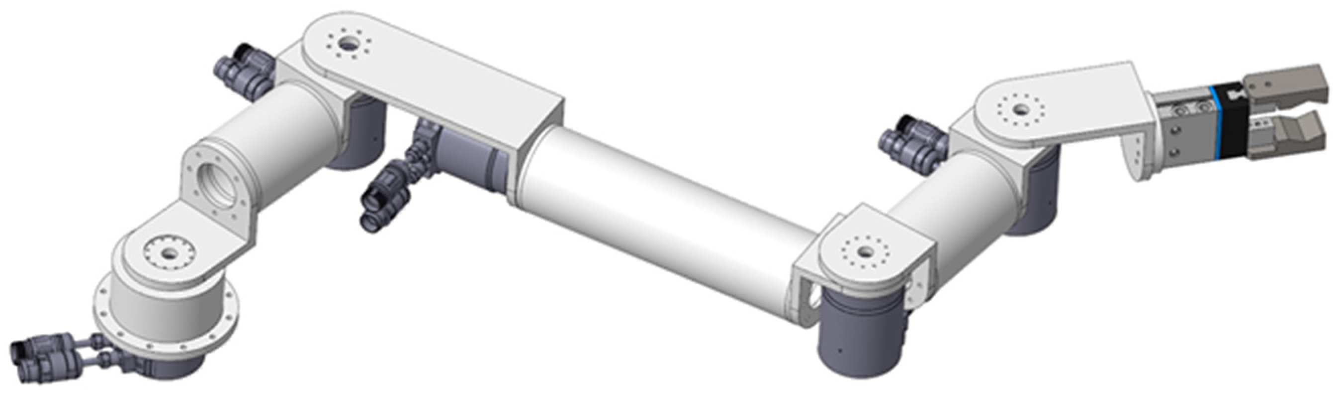
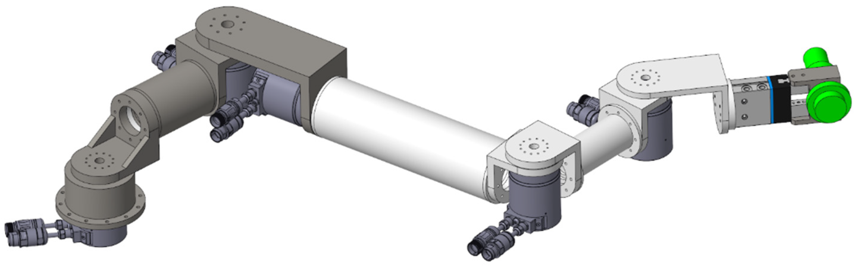
2.2. Cad Model
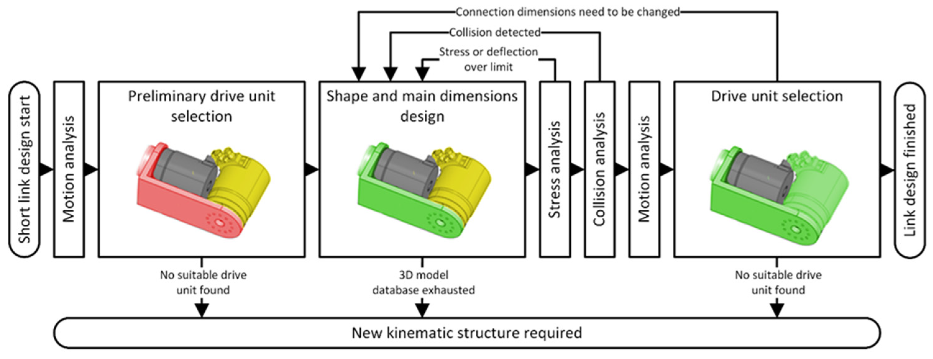
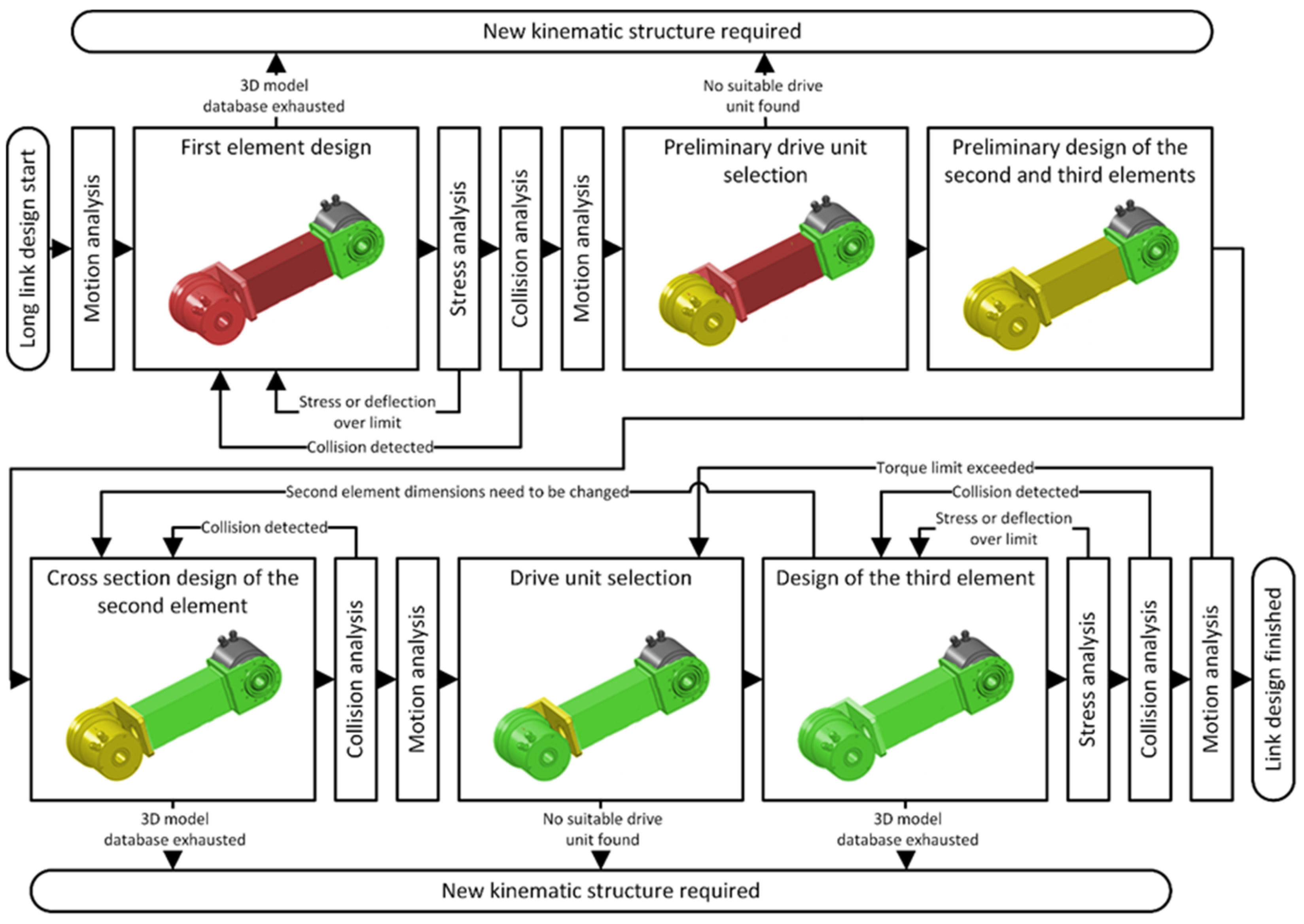
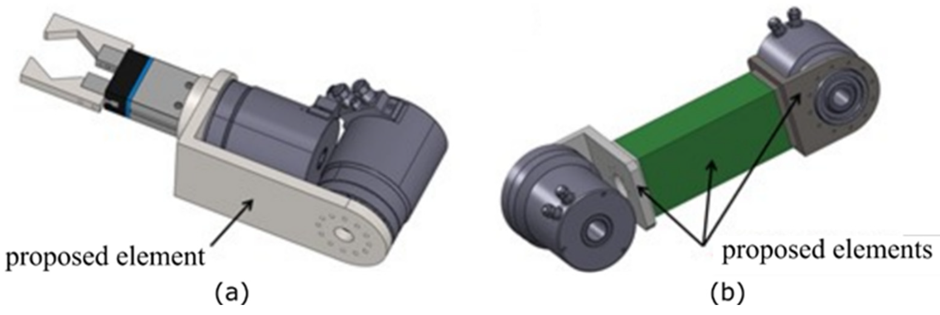
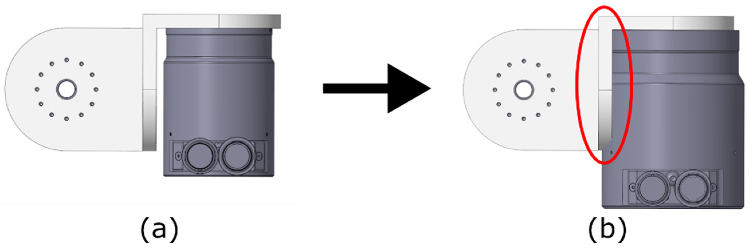
2.2.1. n-th Link Design
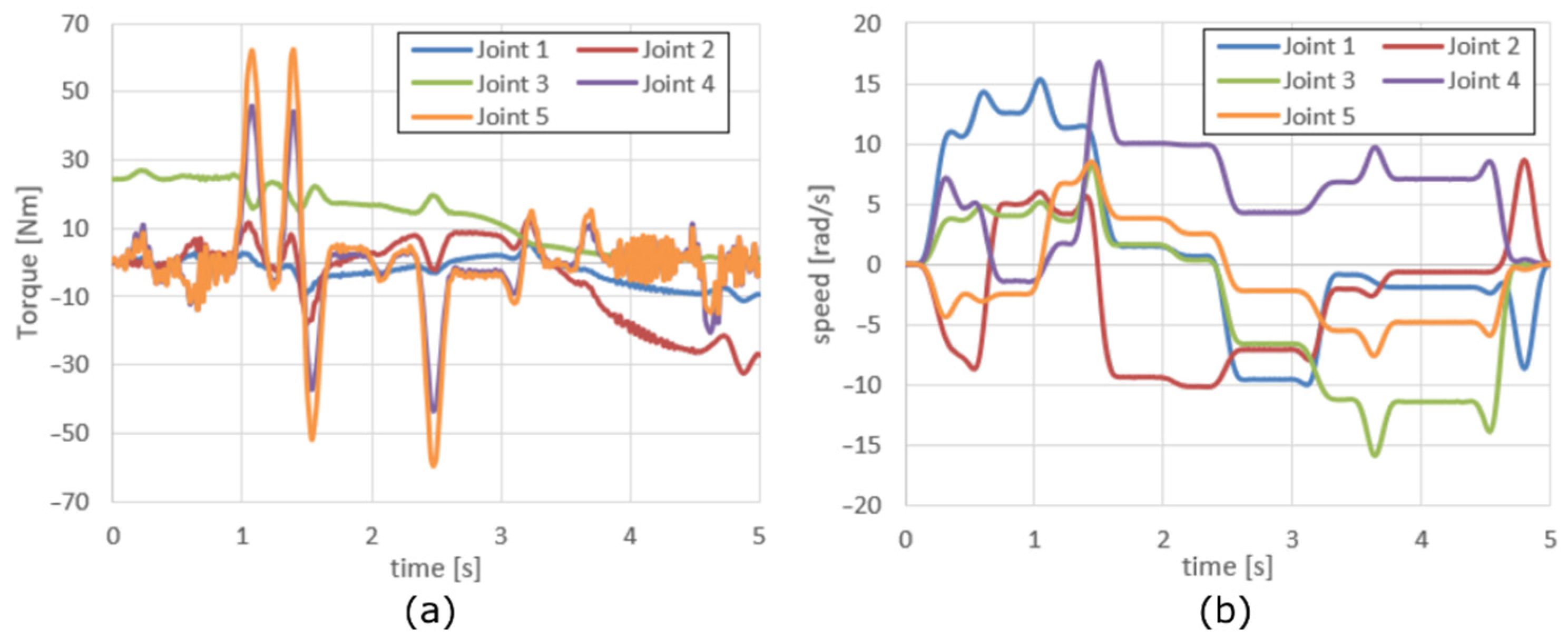
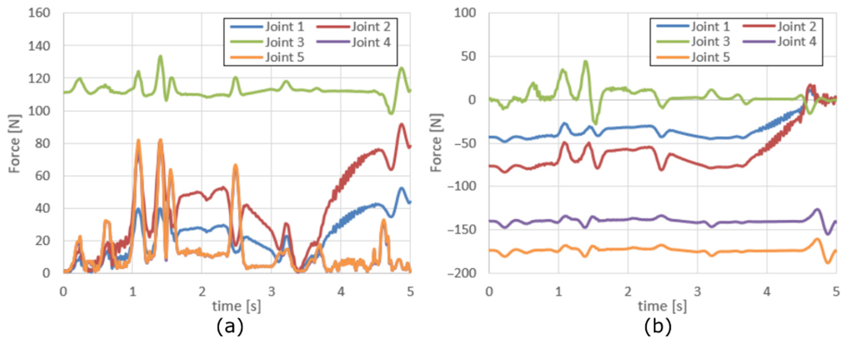
3. Results
4. Discussion
Author Contributions
Funding
Institutional Review Board Statement
Informed Consent Statement
Data Availability Statement
Conflicts of Interest
References
- Verhagen, W.J.C.; Bermell-Garcia, P.; van Dijk, R.E.C.; Curran, R. A critical review of Knowledge-Based Engineering: An identification of research challenges. Adv. Eng. Inform. 2012, 26, 5–15. [Google Scholar] [CrossRef]
- Chapman, C.B.; Pinfold, M. The application of a knowledge based engineering approach to the rapid design and analysis of an automotive structure. Adv. Eng. Softw. 2001, 32, 903–912. [Google Scholar] [CrossRef]
- Reddy, E.J.; Sridhar, C.N.V.; Rangadu, V.P. Knowledge Based Engineering: Notion, Approaches and Future Trends. Am. J. Intell. Syst. 2015, 5, 1–17. [Google Scholar] [CrossRef]
- Xu, Q.L.; Ong, S.K.; Nee, A.Y.C. Function-based design synthesis approach to design reuse. Res. Eng. Des. 2006, 17, 27–44. [Google Scholar] [CrossRef]
- Cui, J.-J.; Wang, D.-Y. Application of knowledge-based engineering in ship structural design and optimization. Ocean Eng. 2013, 72, 124–139. [Google Scholar] [CrossRef]
- La Rocca, G.; Krakers, L.; Van Tooren, M. Development of an ICAD generative model for blended wing body aircraft design. In Proceedings of the 9th AIAA/ISSMO Symposium on Multidisciplinary Analysis and Optimization, Atlanta, Georgia, 4–6 September 2002. [Google Scholar] [CrossRef] [Green Version]
- La Rocca, G.; Van Tooren, M. Enabling distributed multi-disciplinary design of complex products: A knowledge based engineering approach. J. Des. Res. 2007, 5, 333. [Google Scholar] [CrossRef]
- Kim, B.J.; Yun, D.K.; Lee, S.H.; Jang, G.-W. Topology optimization of industrial robots for system-level stiffness maximization by using part-level metamodels. Struct. Multidiscip. Optim. 2016, 54, 1061–1071. [Google Scholar] [CrossRef]
- Tor, S.B.; Lee, S.G.; Britton, G.A.; Zhang, W.Y. Knowledge-based functional design of industrial robots. Int. J. Prod. Res. 2008, 46, 4501–4519. [Google Scholar] [CrossRef]
- Cooper, D.; La Rocca, G. Knowledge-based techniques for developing engineering applications in the 21st century. In Proceedings of the 7th AIAA ATIO Conference, Belfast, Northern Ireland, 18–20 September 2007; Volume 1, pp. 146–167. [Google Scholar] [CrossRef]
- Cooper, S. Achieving Competitive Advantage through Knowledge-Based Engineering: A Best Practice Guide; Deptartment of Enterprise Integration Cranfield University: Cranfield, UK, 1999. [Google Scholar]
- Chocron, O.; Bidaud, P. Evolutionary algorithms in kinematic design of robotic systems. In Proceedings of the IEEE International Conference on Intelligent Robots and Systems, Grenoble, France, 11 September 1997; Volume 2, pp. 1111–1117. [Google Scholar] [CrossRef]
- Paredis, C.J.J.; Khosla, P.K. Kinematic Design of Serial Link Manipulators From Task Specifications. Int. J. Robot. Res. 1993, 12, 274–287. [Google Scholar] [CrossRef]
- Singh, S.; Singla, E. Realization of task-based designs involving DH parameters: A modular approach. Intell. Serv. Robot. 2015, 9, 289–296. [Google Scholar] [CrossRef]
- Automation Technology and Technical Education Solutions | Festo GB. Available online: https://www.festo.com/gb/en/ (accessed on 10 March 2022).
- Competence Leader for Gripping Systems and Clamping Technology—SCHUNK. Available online: https://schunk.com/de_en/homepage/ (accessed on 10 March 2022).
- Home—Zimmer Group. Available online: https://www.zimmer-group.com/en/ (accessed on 10 March 2022).
- Zeman, Z.; Mihola, M.; Suder, J. Design of algorithms for automatic selection of drive units for mechatronic devices. MM Sci. J. 2021, 2021, 4362–4370. [Google Scholar] [CrossRef]


| Parameter | a1 | α1 | a2 | α2 | a3 | α3 |
| Description | Link 1 length | Joint 1 type | Link 2 length | Joint 2 type | Link 3 length | Joint 3 type |
| Upper bound | 1000 | 2 | 1000 | 2 | 1000 | 2 |
| Lower bound | 275 | 0 | 250 | 0 | 225 | 0 |
| End-Effector | Festo DHPS 25-A-N |
|---|---|
| Drive unit 1 | HD Canis Drive 14A (Ratio 80) |
| Drive unit 2 | HD Canis Drive 14A (Ratio 100) |
| Drive unit 3 | HD Canis Drive 17A (Ratio 80) |
| Drive unit 4 | HD Canis Drive 17A (Ratio 80) |
| Drive unit 5 | HD Canis Drive 17A (Ratio 100) |
| Link 2 structural profile | Ø 60 × 2 mm, aluminium |
| Link 3 structural profile | Ø 100 × 3 mm, aluminium |
| Link 4 structural profile | Ø 90 × 3 mm, steel |
| Total weight | 29.75 kg |
Publisher’s Note: MDPI stays neutral with regard to jurisdictional claims in published maps and institutional affiliations. |
© 2022 by the authors. Licensee MDPI, Basel, Switzerland. This article is an open access article distributed under the terms and conditions of the Creative Commons Attribution (CC BY) license (https://creativecommons.org/licenses/by/4.0/).
Share and Cite
Pastor, R.; Mihola, M.; Zeman, Z.; Boleslavský, A. Knowledge-Based Automated Mechanical Design of a Robot Manipulator. Appl. Sci. 2022, 12, 5897. https://doi.org/10.3390/app12125897
Pastor R, Mihola M, Zeman Z, Boleslavský A. Knowledge-Based Automated Mechanical Design of a Robot Manipulator. Applied Sciences. 2022; 12(12):5897. https://doi.org/10.3390/app12125897
Chicago/Turabian StylePastor, Robert, Milan Mihola, Zdeněk Zeman, and Adam Boleslavský. 2022. "Knowledge-Based Automated Mechanical Design of a Robot Manipulator" Applied Sciences 12, no. 12: 5897. https://doi.org/10.3390/app12125897