Article

Closed-Circuit Pump-Controlled Electro-Hydraulic Steering System for Pure Electric Wheel Loader

1
College of Mechanical Engineering and Automation, Huaqiao University, Xiamen 361021, China
2
State Key Laboratory of Fluid Power and Mechatronic Systems, Zhejiang University, Hangzhou 310027, China
3
Fujian Key Laboratory of Green Intelligent Drive and Transmission for Mobile Machinery, Xiamen 361021, China
*
Author to whom correspondence should be addressed.
Appl. Sci. 2022, 12(11), 5740; https://doi.org/10.3390/app12115740
Submission received: 10 April 2022 / Revised: 29 May 2022 / Accepted: 30 May 2022 / Published: 5 June 2022

Abstract

:
Traditional construction machinery’s full hydraulic steering system has high energy consumption. An electro-hydraulic flow matching steering system for electric wheel loaders based on closed-circuit pump control is proposed to solve the problem. The transfer function of the electro-hydraulic system is established, and the system is stable according to analysis via Routh matrix. A test platform is built to verify the effectiveness of the system and the control strategy. Taking a 1.6T wheel loader as an example, the energy consumption of the traditional steering system and the new steering system under zero-load, positive-load (shovel loaded with 600 kg gravel), and offset-load (the center of gravity of the gravel is off the center of the bucket) conditions is compared. The results show that the energy consumption of the proposed steering system is greatly reduced compared to the traditional system. Under the condition of zero-load with medium steering speed, compared to the traditional system, consumption is reduced by 22.8%.

1. Introduction

The loader is a kind of engineering machinery widely used in construction engineering, which is used for transporting small lumpy materials such as soil, coal, lime, sand, and other materials. The steering system of the loader controls the direction of travel of the loader, and the actual operation of the loader requires frequent steering with load or zero-load. Most commercial wheel loaders use engine-driven dosing pumps to supply oil to the steering system and working device, which will cause a large amount of overflow loss and throttling loss. Pure electric drive has become one of the main driving methods of construction machinery with its huge advantage of zero-emissions [1,2,3]. There are a large number of loaders, among which articulated loaders are the most widely used. In a working cycle of the wheel loader, the energy consumed by the steering system accounts for about 22.2% of the total output energy of the power source [4,5]. It is significantly important to reduce throttling loss and overflow loss as well as realize on-demand oil supply of steering system for energy saving and emission reduction of wheel loaders.
The steer-by-wire system can effectively improve the traditional steering system’s mechanical and hydraulic steering performance and enhance the driving experience [6,7,8]. At present, steer-by-wire has been widely used in the automotive field. Researchers have carried out in-depth research on the state observation, variable transmission ratio, and state feedback control theory of steer-by-wire vehicles [9,10,11]. Junaid et al. combined the adaptive synovial observer and Kalman filter method to obtain the vehicle state and used the adaptive global fast synovial strategy to control the vehicle steer-by-wire system [12]. Yih P. et al., proposed a method for estimating vehicle sideslip angle using steering moment information by combining a linear vehicle model with a steering system model, designing a simple observer to estimate the sideslip during transverse sway rate and steering angle measurements, and developing a state feedback control based on the estimation of sideslip angle to effectively change the vehicle handling characteristics through active steering intervention [13]. The steer-by-wire system cancels the mechanical connection between the steering wheel and the steering actuator, so the driver cannot feel the real road conditions. To solve this problem, scholars had carried out in-depth research and analysis of road sense control theory [14,15,16]. Xiao et al. studied and designed the fusion algorithm for road feeling control. This is a comprehensive road feeling control strategy including main control and auxiliary control, damping control, and limit control that is proposed based on the direct measurement of steering motor current and vehicle speed, steering handle angle, and other state variables, but no real vehicle detection experiment was carried out [17]. Other scholars have studied the reliability and safety problems of steering-by-wire systems due to structural changes compared to the traditional steering system [18,19,20]. However, in the field of construction machinery, the research on steer-by-wire systems is very limited.
According to the classification of the hydraulic circuit, the electro-hydraulic steering system of construction machinery can be divided into the open steering system and the closed steering system. To reduce the energy consumption of open systems, several scholars have studied the control of hydraulic valves and hydraulic pumps in the circuit. Linjama et al. used pulse-coded modulation to control the low-cost on/off valve group to achieve step-by-step control of the actuator inflow and outflow. An important advantage of this system is its ability to control both the pressure level and speed of the actuator, and the optimization of the pressure level allows the use of lower supply pressures and increases efficiency, but the system still suffers from overflow losses, and the stability or robustness of the system is not analyzed in the paper [21]. Quan et al., proposed a flow-matched steering control method using a servo motor to independently drive a dosing pump, which eliminated overflow losses and reduced the standby energy consumption of the steering system, saving about 16% compared with a load-sensitive steering system, but the system still had a small number of throttling losses [22]. Dellamico et al., proposed a closed-center electro-hydraulic open steering system, which uses a constant pressure source to independently supply oil to the steering cylinders through four electronically controlled proportional throttle valves. Compared to the original system, the proposed system can improve the steering smoothness and reduce energy loss, but the specific steering conditions are not analyzed in this paper [23].
Although the open steering system can achieve the reduction of energy consumption by control methods, the pressure difference of the hydraulic valve still leads to energy loss, so some scholars have researched the application of a closed system for hydraulic steering. Minav et al., used direct drive hydraulic transmission to implement the function of the two-cylinder hydraulic power transmission system, and the function of the system was verified by the test bench Dolores model, which laid the foundation for future research based on this test bench, but the energy consumption analysis of the system based on actual working conditions was not carried out in this paper [24]. Ivantysynnova et al. proposed a closed wire-controlled variable pump steering system, which controls the displacement of the variable pump by collecting vehicle signals. Under the same operating conditions, the variable displacement pump in-line closed steering system saves 14.5% fuel compared with the traditional loader steering system, but the analysis in the paper is still based on the traditional fuel-based loader and does not investigate the electrification of the loader [25]. Pu et al. developed a new loader steering system based on the closed pump cylinder variable speed control principle, which changes the rotation direction of the servo motor and the steering direction and speed of the loader are controlled by changing the rotation direction and speed of the servo motor, which completely avoids the throttling loss, and the steering system has high smoothness and the energy consumption efficiency of the steering system reaches 80% using simulation analysis; however, there is no comparison with the energy consumption of the traditional steering system, and there is no further verification of the energy consumption efficiency of the system by experiment [26].
As mentioned above, in the open steering system the throttling loss cannot be eliminated due to the existence of the reversing valve. Therefore, the closed-loop pump control system that eliminates the hydraulic reversing valve has great energy-saving advantages and application prospects. An electro-hydraulic flow matching steering system for electric wheel loaders based on closed-circuit pump-control is proposed for the shortcomings of the traditional steering system used in electric loaders, combined with wire-controlled steering technology. The steering system uses the servo motor to drive the hydraulic pump to supply oil independently, correlates the tilt angular speed of the electric control handle with the speed of the servo motor, and makes them into a certain proportional relationship so that the hydraulic pump outputs the oil matching the flow required by the steering hydraulic system to the steering hydraulic cylinder, which eliminates energy loss caused by throttling and overflow of the hydraulic steering system to achieve the purpose of energy-saving. The paper is organized as follows: Section 2 introduces the working principle of the steering system. Section 3 analyzes the system characteristics. Section 4 introduces the closed-loop control strategy for the steering angle of the loader. Section 5 presents the experimental findings. Section 6 is the conclusion.

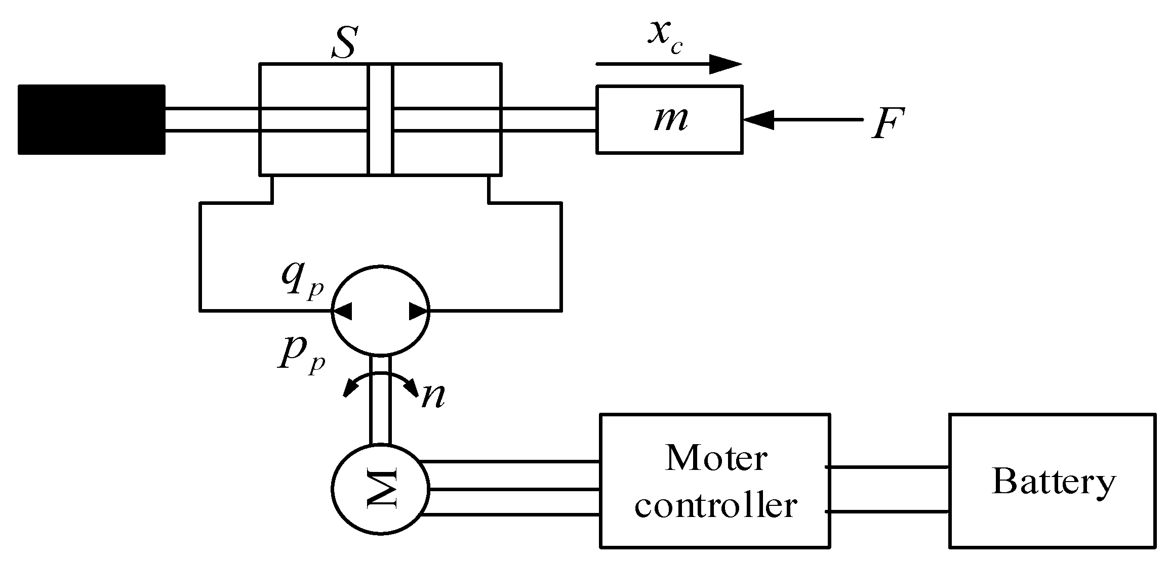
2. Working Principle

The schematic diagram of the proposed system is shown in Figure 1. The steering system uses a permanent magnet synchronous motor to drive the pump of the closed hydraulic circuit so that the steering-by-wire and flow matching of the loader is realized. By collecting the tilt angle of the electronic control handle, the controller converts it into the target steering angle of the loader, which is regarded as the target value of closed-loop control θ*. The displacement of the steering cylinder is converted into the current steering angle of the loader by the controller as the feedback of the closed-loop control θ. The difference between them is the control deviation θe, which is the input of the controller. After adjusting, the motor controller outputs the motor speed signal n to control the flow from the motor pump to the steering cylinder and to control the output displacement of the steering cylinder, that is, to control the actual steering angle of the loader, so that the steering angle of the loader follows the tilt angle of the electric control handle.
Compared to the traditional steering system, the proposed system has the following characteristics:
(1)
The closed-circuit pump-control system is adopted and the throttling loss and overflow loss of the traditional steering system can be avoided.
(2)
Permanent magnet synchronous motor is used as the driving motor, which has good speed regulation characteristics and dynamic response characteristics. According to the requirements of working conditions, variable speed flow matching is satisfied, and flow pressure high-frequency response is realized.
(3)
The electronic control handle is used as the steering control lever, which has good response characteristics and steering accuracy and requires a small range of movement, greatly reducing the labor intensity of the driver.

3. System Characteristic Analysis

To analyze the control performance of the proposed closed-circuit pump-controlled steering system, the mathematical model of the system is built.
According to the mechanical structure of the loader steering system, the equation of motion of the displacement piston rod of the steering cylinder and the steering angle of the loader is derived, calculated with MATLAB, and the outputs of the corresponding relationship are shown in Figure 2.
The resulting equation is linearized and can be expressed as
θ = k 1 x c
where xc is the displacement of the steering cylinder, θ is the steering angle, and k1 is the proportional coefficient.
The steering angle is set by the controller to be proportional to the handle angle. The relationship can be given as
θ h = k 2 θ
where θh is the handle tilt angle, and k2 is the proportional coefficient.
To simplify the analysis, the following assumptions are made.
(1)
Left and right steering cylinders are simplified as double-acting cylinders.
(2)
The system relief valve is always closed.
(3)
The oil in the closed system is sufficient.
The schematic diagram of Figure 1 can be simplified and plotted in Figure 3.
The control method of the system is angle closed-loop control, which keeps the steering angle proportional to the handle angle. The control principle is shown in Figure 4.
After the Laplace transformation of Equations (1) and (2), the following results are obtained as
θ ( s ) = k 1 X c ( s )
θ H ( s ) = k 2 θ ( s )
The basic model of PID is as follows
θ e = θ * θ
N * ( s ) θ e ( s ) = K P + K I s + K D s
As shown in Figure 3, G1(s) is an electrical system link and it can be treated as a first-order inertia link. The motor response equation can be expressed as
τ 1 d n d t + n = n *
where τ1 is the motor response time constant. n is the actual rotary speed of the motor. n* is the target rotary speed of the motor.
By taking the Laplace transform for Equation (7), the transfer function can be obtained as
G 1 ( s ) = N ( s ) N * ( s ) = 1 τ 1 s + 1
The output flow equation of the hydraulic pump can be given as
q p = V p n C p ( p p p i )
where Vp is the displacement of the hydraulic pump. Cp is the leakage coefficient of the hydraulic pump. pp is the outlet pressure of the hydraulic pump. pi is the inlet pressure of the hydraulic pump.
The flow rate flow into the cylinder can be expressed as
q c = S d x c d t + V pc β d ( p p p i ) d t
where S = A + a. A is the area of the steering cylinder rodless chamber. a is the area of the rod chamber of the steering cylinder. Vpc is the chamber volume between the closed pump and steering cylinder. β is the effective elastic modulus of oil.
The force balance equation of the steering cylinder can be expressed as
S ( p p p i ) = m d 2 x c d t 2 + B m d x c d t + K x c + F
where m is the mass converted to the piston for the steering cylinder piston and load. Bm is the viscous damping of the steering cylinder piston and load. K is the spring stiffness of the load. F is the load force.
Laplace transform of Equations (9)–(11) can be obtained
Q p ( s ) = V p N ( s ) C p P p ( s ) + C p P i ( s )
Q C ( s ) = S X c ( s ) s + V pc β P p ( s ) s V pc β P i ( s ) s
S P p ( s ) S P i ( s ) = m X c ( s ) s 2 + B m X c ( s ) s + K X c ( s )
The simultaneous Equations (12)–(14) can be obtained
X c ( s ) = V p N ( s ) S m V pc β s 3 + C p m s 2 + ( K V pc β + C p B m + S 2 ) s + K C p
From Equation (15), the open-loop transfer function of steering cylinder displacement and motor speed can be obtained as
G 2 ( s ) = X c ( s ) N ( s ) = V p S m k g s 3 + C p m s 2 + ( K k g + C p B m + S 2 ) s + K C p
where k g = V pc β . G2(s) is the hydraulic system link.
For the control block diagram shown in Figure 3, to clarify its basic characteristics the simplest control strategy, proportional control, can be adopted. Referring to Equations (6), (8) and (16), the open-loop transfer function of the closed-circuit pump-controlled steering system can be listed
G ( s ) H ( s ) = K V τ 1 m k g s 4 + m ( k g + k g ) s 3 + [ τ 1 ( K k g + S 2 ) + k g B m + C p m ] s 2 + ( K k g + K k g + C p B m + S 2 ) s + K C p
where K V = V p S k 1 K P is the open-loop gain. Through the stability analysis of the system, the characteristic equation G ( s ) H ( s ) + 1 = 0 for the closed-loop system can be obtained, which is brought into Equation (17) as follows
τ 1 m k g s 4 + m ( k g + k g ) s 3 + [ τ 1 ( K k g + S 2 ) + k g B m + C p m ] s 2 + ( K k g + K k g + C p B m + S 2 ) s + K C p + K V = 0
The Routh matrix of the system can be expressed as
| s 4 τ 1 m k g τ 1 ( K k g + S 2 ) + k g ' B m + C p m K C p + K V s 3 m ( k g ' + k g ) K k g ' + K k g + C p B m + S 2 0 s 2 k g ' 2 B m + m k g ' C p + m k g C p + τ 1 k g ' S 2 k g ' + k g K C p + K V 0 s 1 k g ' B m ( K k g ' + K k g + C p B m + S 2 + k g ' S 2 ) + m C p ( C p B m + S 2 ) ( k g ' + k g ) + τ 1 k g ' S 2 ( K k g ' + K k g + S 2 ) k g ' 2 B m + m k g ' C p + m k g C p + τ 1 k g ' S 2 0 0 s 0 K C p + K V 0 0 |
Combined with the actual parameters of each element, it can be seen that the parameters of the closed-loop transfer function are all positive. Additionally, the first column of the Routh matrix is all addition and multiplication operations. Therefore, it can be concluded that the first column of the Routh matrix is all positive numbers. The novel system is stable.

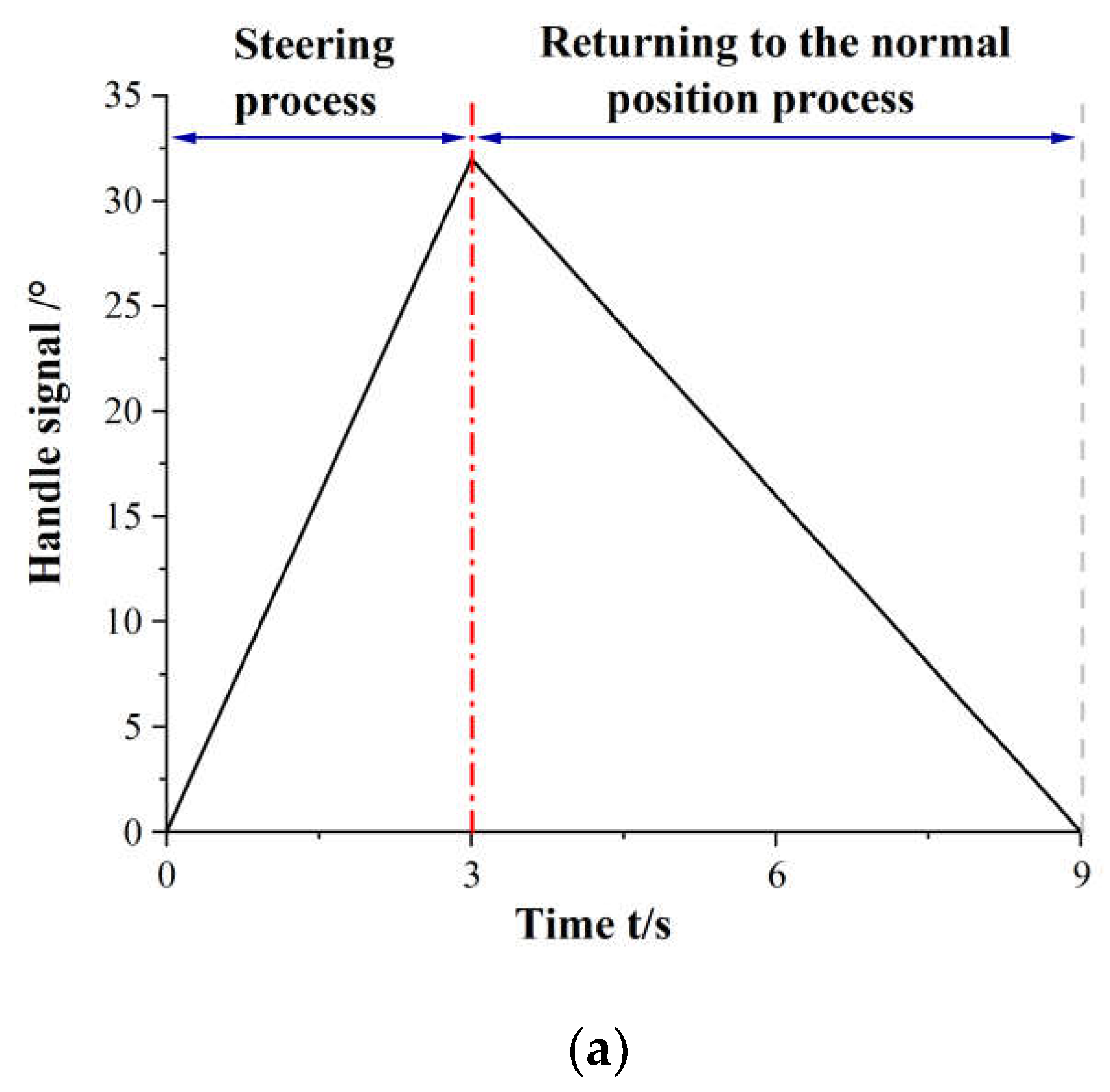
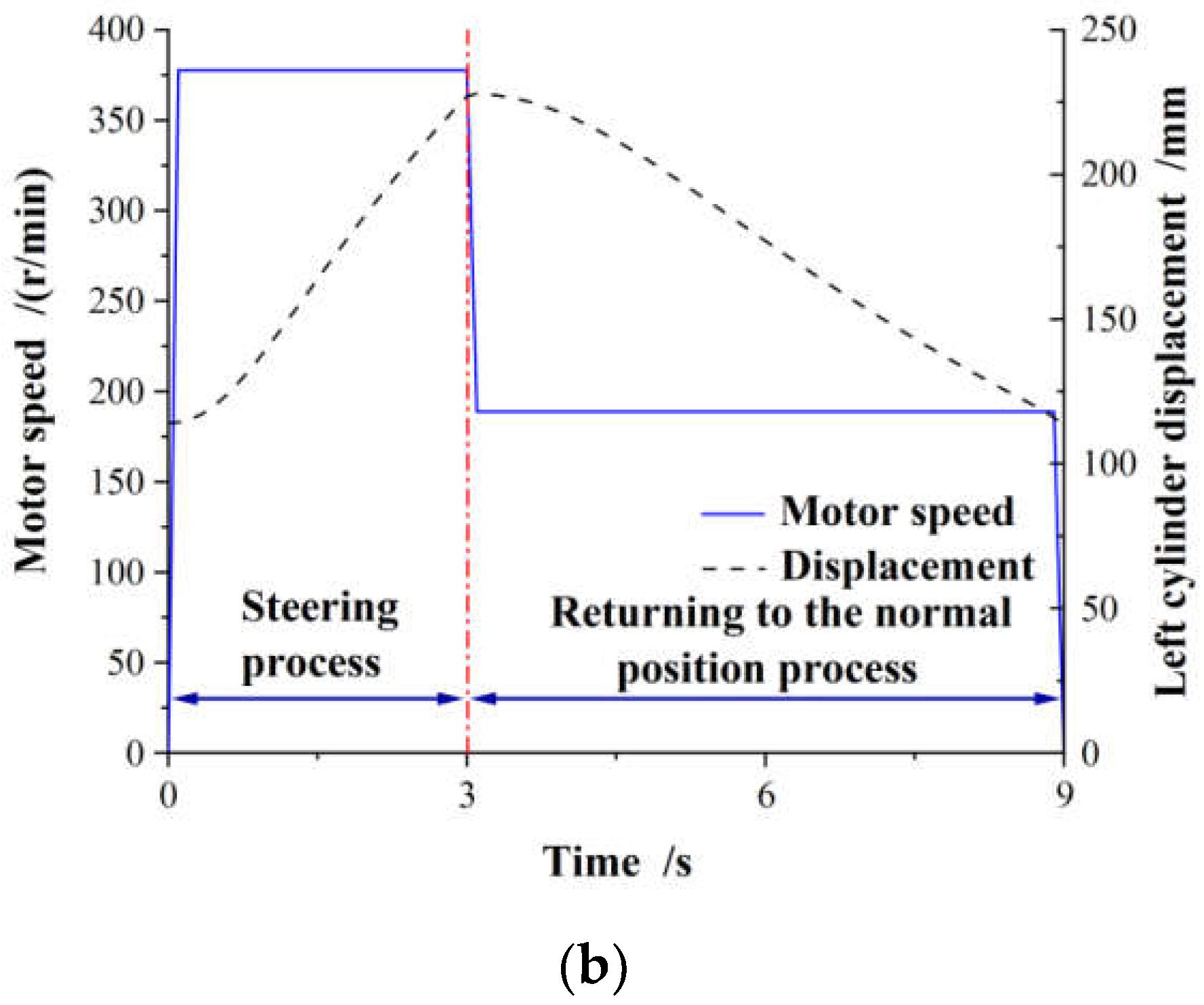
4. Closed-Loop Control Strategy of the Steering Angle

The steering of the loader is realized by the movement of the steering cylinder. By controlling the displacement of the piston rod of the steering cylinder, the closed-loop control of the steering angle for the loader can be realized, and the steering angle of the loader can follow the angle of the electronic control handle. At the same time, according to the speed of the electronic control handle, motor speed is controlled to achieve the steering state of the loader and follow the tilt state of the handle.
To realize closed-loop control of the steering angle of the loader, it is necessary to make full use of motor variable speed control technology. Taking the flow of the traditional loader steering system as a reference, according to the flow range of the traditional loader steering device, the motor speed range can be calculated according to the flow range and can be expressed as
n = { n m i n   ,     n < n m i n n ,   n m i n   n n m a x n m a x   ,     n > n m a x
where n′ is the target output speed calculated by the system.
According to the above calculation, the flow chart of the closed-loop control strategy of the steering angle for the loader is shown in Figure 5. Through the closed-loop control strategy of loader steering angle, the angle can accurately correspond to the angle of the electronic control handle, realize accurate steering, and improve the controllability of the system.
To verify the following state of the loader steering angle and motor speed relative to the handle steering signal, two different handle input steering signals are set as shown in Figure 6a. The time for returning to the normal position process is twice that of the steering process. As shown in Figure 6b, the motor speed remains unchanged during the steering process and returns to the normal position process. Motor speed during the steering process is twice that of returning to the normal position process. The displacement of the steering cylinder also changes approximately linearly with the steering signal of the handle (Figure 6b). This shows that the closed-loop control of the steering angle of the loader is feasible.

5. Experimental Research

5.1. Calculation of Loader Steering Efficiency

The pressure sensor and displacement sensor are used to collect the cylinder pressure, pump pressure, and cylinder displacement to calculate the output power of the pump, the consumed power of the cylinder, and the steering efficiency of the system.
The pump output power can be expressed as
P p = p p ( A L h v L + A R h v R ) p i ( A L l v L + A R l v R )
where Pp is the pump output power. pp is the pump outlet pressure. p i is the pump inlet pressure. When the loader turns right, ALh is the effective working area of the rodless cavity of the left steering cylinder, ARh is the effective working area of the rod cavity of the right steering cylinder, ALl is the effective working area of the rod cavity of the left steering cylinder, ARl is the effective working area of the rodless cavity of the right steering cylinder; when the loader turns left, ALh is the effective working area of the rod cavity of the left steering cylinder, ARh is the effective working area of the rodless cavity of the right steering cylinder, ALl is the effective working area of the rodless cavity of the left steering cylinder, and ARl is the effective working area of the rod cavity of the right steering cylinder. vL and vR are the speeds of the left and right steering cylinder pistons, respectively, which can be obtained through the differential displacement signal of the steering cylinder.
The power consumed by the steering cylinder during steering can be described as
P c = p h ( A L h v L + A R h v R ) p l ( A L l v L + A R l v R )
where Pc is the power consumed by the steering cylinder during the steering process. ph is the pressure in the high-pressure chamber of the cylinder. pl is the pressure in the low-pressure chamber of the cylinder.
The steering efficiency of the system can be obtained
η z = P cl d t + P cr d t P p d t × 100 %
where ηz is the steering efficiency of the system. Pcl and Pcr are the power consumption of the left and right steering cylinders, respectively.

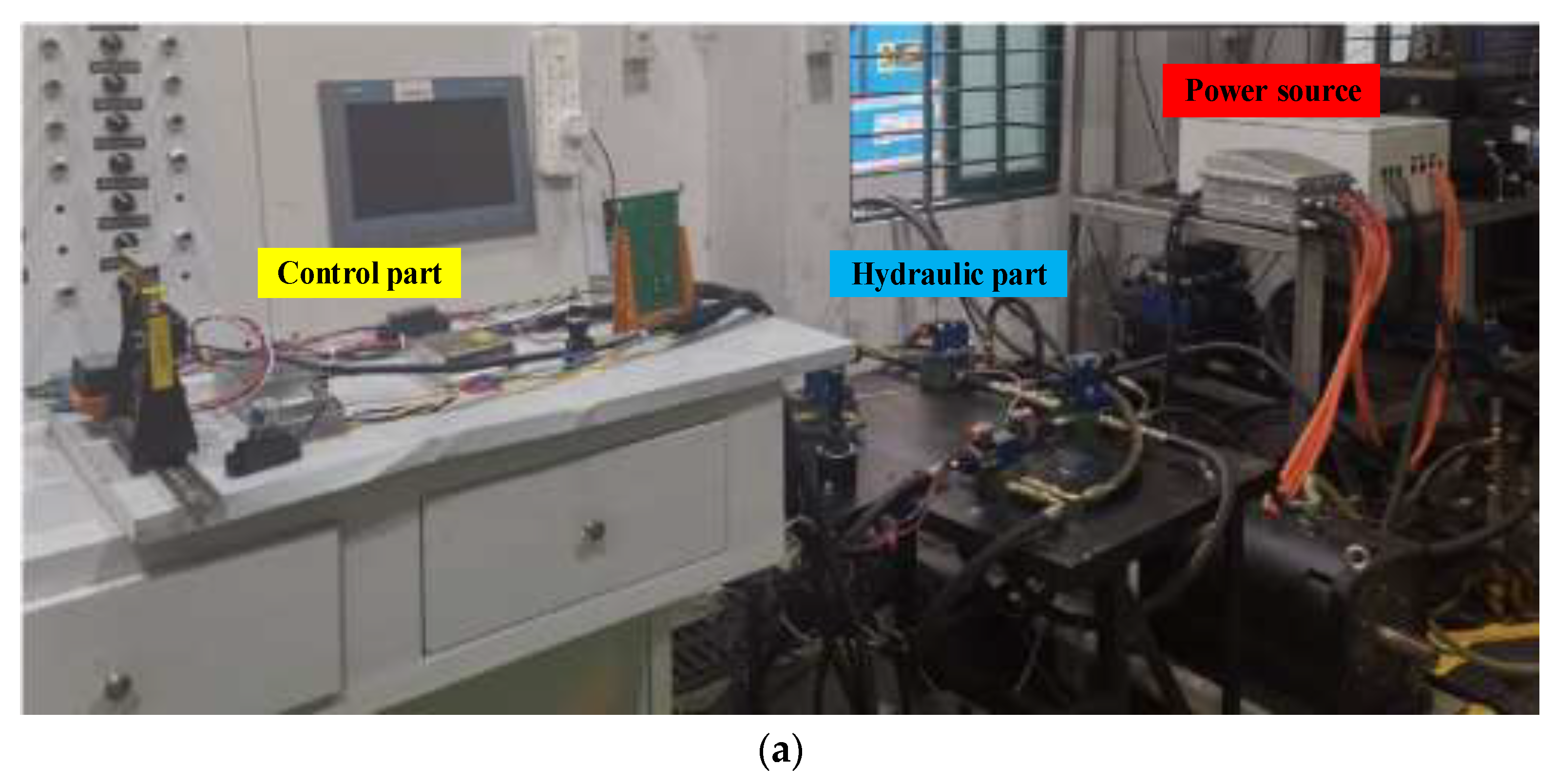
5.2. Experimental Platform

To verify the working performance of the closed-circuit pump-controlled electro-hydraulic flow matching steering system, a steering system test platform is built as shown in Figure 7. To facilitate the test research, the test platform of the steering system is separated from the loader. The output of the motor pump of the test platform is connected to the oil inlet of the steering cylinder of the loader, and each component of the test platform is debugged and controlled. The key component parameters of the system are shown in Table 1. The system realizes the information and data exchange among the platform components through the CAN bus communication network, including oil cylinder displacement, each key point pressure, steering signal of the electric control handle, and motor speed. The motor is supplied via power grid which is converted into high voltage DC by an AC/DC module to drive the motor pump work.
The steering system energy consumption test prototype is a 1.6T electric wheel loader. The steering hydraulic system of the prototype is a full hydraulic load-sensitive steering system, as shown in Figure 8. The steering system can preferentially distribute the pump output flow through the priority valve, but there will still be overflow and throttling losses. To study the effects of different loading methods and varying steering speeds on efficiency, load conditions were divided into zero-load, positive-load, and offset-load. The steering speed was refined into low-speed steering, medium-speed steering, and high-speed steering in each condition. In the zero-load condition, about 600 kg of material is placed in the bucket with its center of gravity at the center of the bucket; in the off-load condition, about 600 kg of material is placed at one end of the bucket with its center of gravity at about 1/4 of the length of the bucket. All tests were conducted on concrete pavement, as shown in Figure 9.

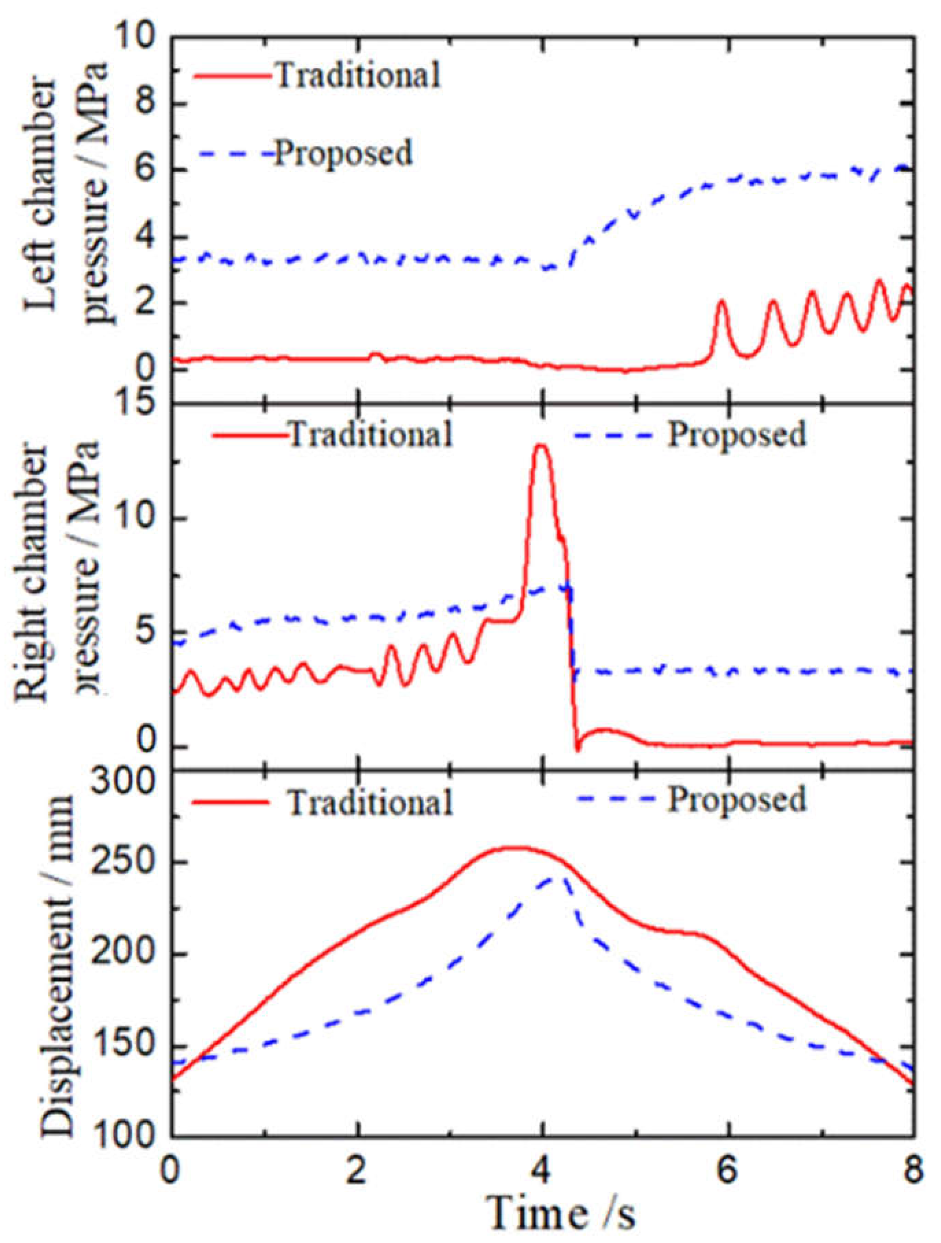
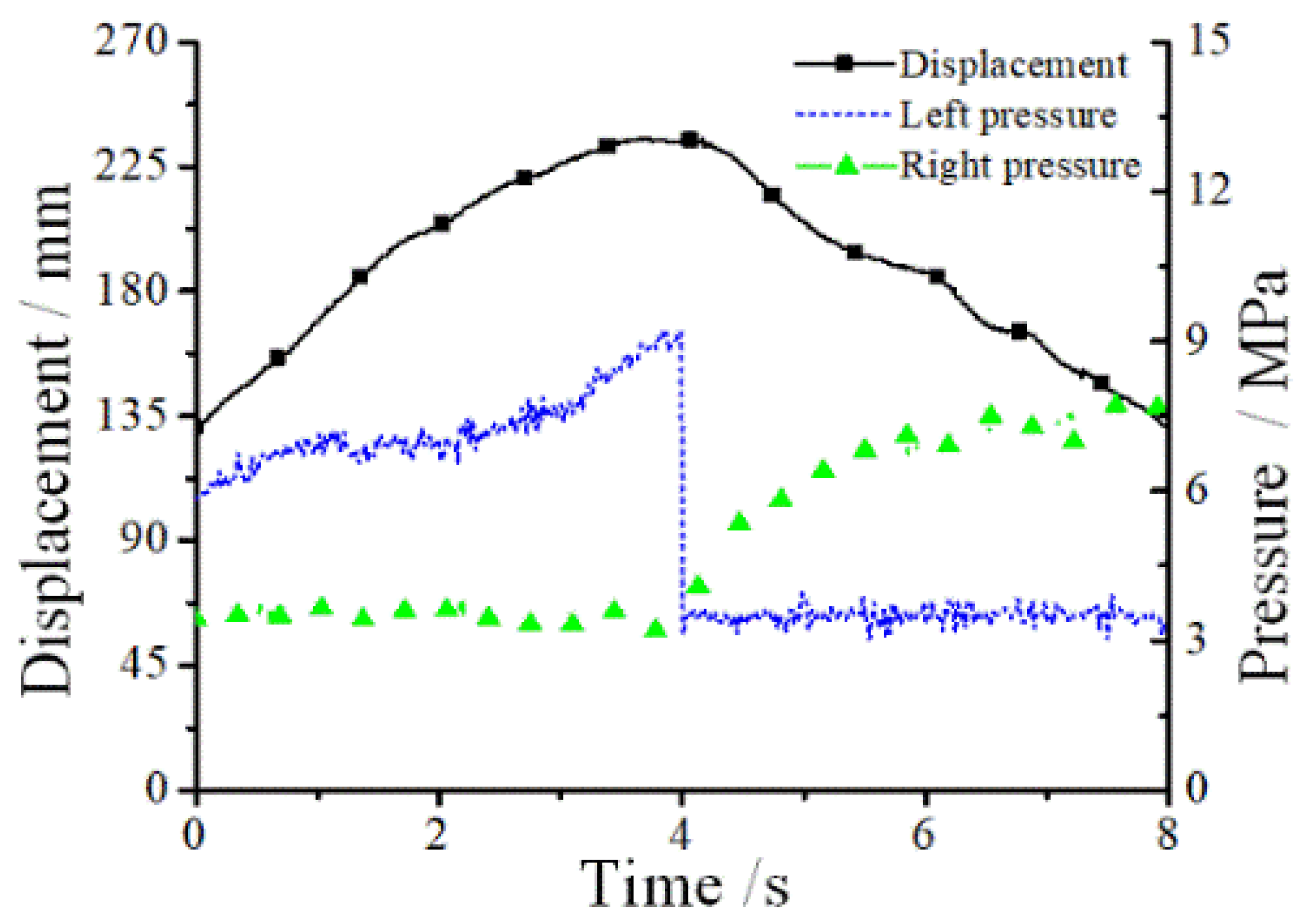
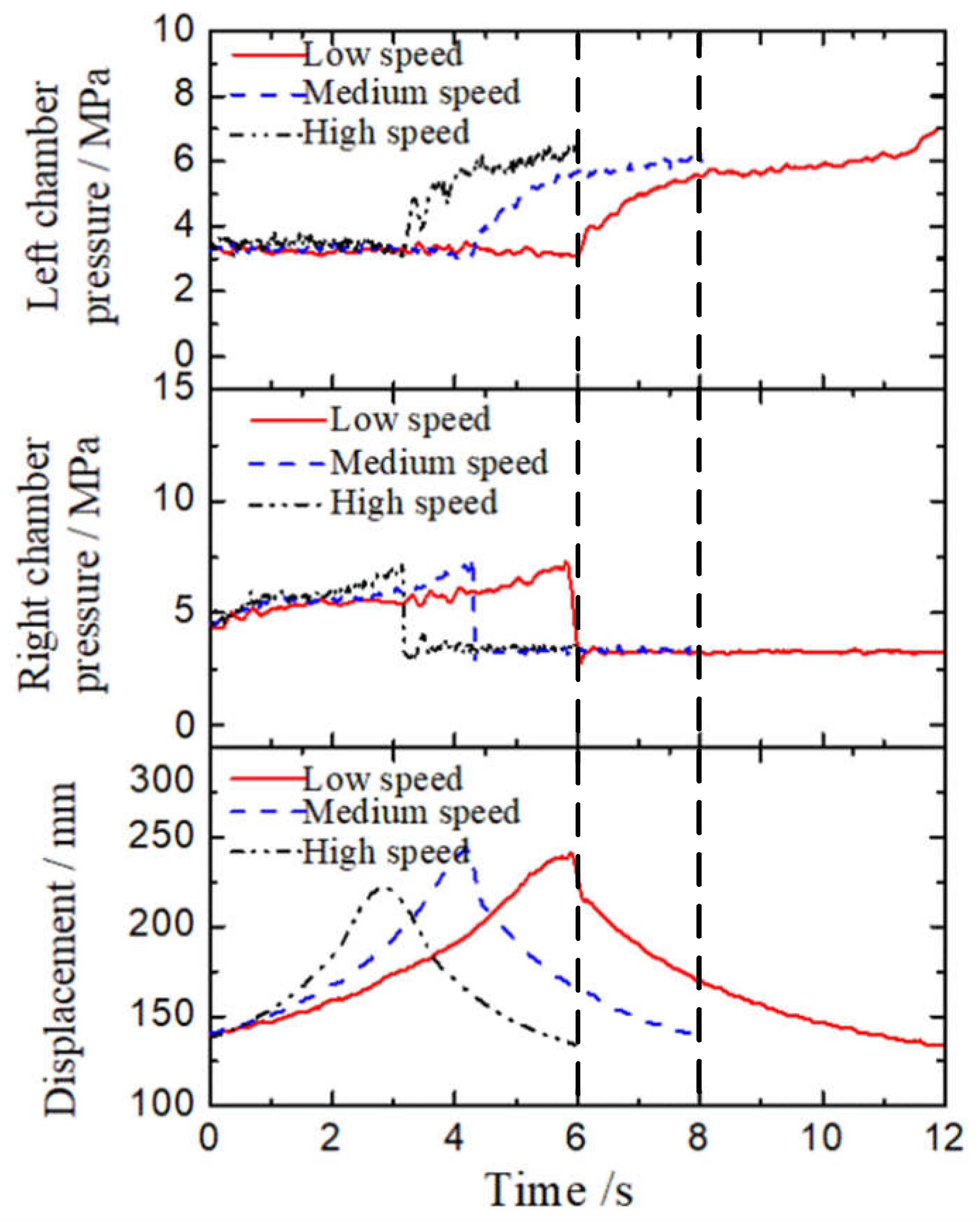
5.3. Experimental Results and Analysis

  • Steering under the zero-load condition
Figure 10 shows the comparisons between the traditional steering system and the proposed system under zero-load conditions. In the period of 0~4 s the loader turns to the left, and in the period of 4~8 s the loader turns back to the right. Both the displacements of the steering cylinder pistons show that the loader steering process is correct. As the loader turns to the left first, the right chamber pressure of the steering cylinder is higher than the left. The pressure has a pulse in the traditional system which needs much more energy, while in the proposed system the pressure is much smoother. According to Equations (22)–(24), steering efficiency of the traditional system is 63% and that of the proposed system is 81.6%. This means that the consumption of the system is reduced by 22.8% compared to the traditional system.
2.
Steering under normal load condition
Figure 11 shows the test curves of the displacement and the pressure of the steering cylinder under the normal load condition. It can be seen that the pressure variation trend of the rodless chamber of both sides of the steering cylinder is similar to that of the zero-load condition. The difference is that the pressure of the high-pressure chamber of the steering cylinder increases compared to the zero-load condition. The maximum pressure of the left steering cylinder when the loader turns to the left is 9.2 MPa, while that under the zero-load condition is 7.5 MPa. The maximum pressure of the left steering cylinder when the loader turns back to the right is 3.9 MPa and the maximum pressure of the right steering cylinder is 7.77 MPa. Based on the test results, the calculated steering efficiency is 90.2%. This means that loader steering efficiency is improved in the normal load condition compared to the zero-load condition.
3.
Steering under offset load condition
Figure 12 shows the test curves of the displacement and the pressure of the steering cylinder under the offset load condition. It has similar test curves for displacement and pressure, except the pressure fluctuation is larger than the normal load condition. The maximum pressure of the left steering cylinder when the loader turns to the left is 9.4 MPa, while the loader turns back to the right the maximum pressure is 4.3 MPa. The maximum pressure of the right steering cylinder is 8.43 MPa. All the pressures under the offset load condition are larger than those under the normal load condition. Based on the test results, steering efficiency with the offset load is 89.1%, which is lower than that with a normal load.
4.
Steering under different steering speeds
This experiment is under the zero-load condition to analyze the influence of steering speed on displacement and pressure. Figure 13 shows the displacement and pressure of the steering cylinders with different steering speeds. With the increase of steering speed, the steering time decreases accordingly. The displacement of the steering cylinder with a high steering speed is a little shorter than the other two steering speeds. The maximum pressures of the steering cylinders are almost the same for the three different steering speeds. Steering efficiency under the low steering speed, medium steering speed, and high steering speed is 81.2%, 81.6%, and 82.5%, respectively. This indicates that the higher the steering speed is, the higher the steering efficiency can become.

6. Conclusions

To improve the energy efficiency of the steering system, an electro-hydraulic flow matching steering system for electric wheel loaders based on closed-circuit pump control is proposed. According to the tilt speed of the electric control handle, the angle of the loader is controlled in a closed-loop based on variable speed control in order to control the speed of the powerful motor and realize the flow matching of the supply and demand of the steering system. Through the simulation experimental study of the proposed steering system and the analysis of energy consumption efficiency, the following results can be concluded:
(1)
Through the closed-loop control strategy for the steering angle of the loader, the steering angle can accurately correspond to the angle of the electric control handle to achieve precise steering and improve the controllability of the loader steering system. Additionally, with the electric control handle as the steering lever, the mechanical connection of the traditional steering wheel is eliminated. Compared to the traditional steering wheel steering on the loader, the control range of the electric control handle is small, which greatly reduces the driver’s labor intensity. It provides a basis for electronic control development of the subsequent loader steering device.
(2)
Under various working conditions of in-place steering, the steering efficiency of the proposed closed-circuit pump-controlled electro-hydraulic flow matching steering system is more than 80%, which is higher than that of the loader’s traditional full hydraulic steering system. The energy consumption of the proposed system is reduced and the energy utilization of the proposed system is improved. It provides a reference for research into potential energy-saving of loader steering systems.
(3)
Using the proposed closed-circuit pump-controlled electro-hydraulic flow matching steering system, with increasing steering speed the steering efficiency increases accordingly. When the material is placed in the center of the loader bucket, the steering efficiency is also higher than that of the offset load and zero-load condition.

Author Contributions

Writing and analyzing, T.G. and B.W.; conceptualization and supervision, T.L.; data curation, H.C.; methodology, Q.C. All authors have read and agreed to the published version of the manuscript.

Funding

This research was funded by the National Key Research and Development Program of China (2020YFB2009900), the Natural Science Foundation of Fujian Province, China (2021J01295), National Natural Science Foundation of China (51875218 & 51905180), the Open Foundation of the State Key Laboratory of Fluid Power and Mechatronic Systems (GZKF-202026).

Institutional Review Board Statement

Not applicable.

Informed Consent Statement

Not applicable.

Data Availability Statement

Not applicable.

Conflicts of Interest

The authors declare no conflict of interest.

References

  1. Lin, T.; Lin, Y.; Ren, H.; Chen, H.; Li, Z.; Chen, Q. A double variable control load sensing system for electric hydraulic excavator. Energy 2021, 223, 119999. [Google Scholar] [CrossRef]
  2. Lajunen, A.; Sainio, P.; Laurila, L.; Pippuri-Mäkeläinen, J.; Tammi, K. Overview of Powertrain Electrification and Future Scenarios for Non-Road Mobile Machinery. Energies 2018, 11, 1184. [Google Scholar] [CrossRef] [Green Version]
  3. Bilgin, B.; Magne, P.; Malysz, P.; Yang, Y.; Pantelic, V.; Preindl, M.; Korobkine, A.; Jiang, W.; Lawford, M.; Emadi, A. Making the case for electrified transportation. IEEE Trans. Transp. Electrif. 2015, 1, 4–17. [Google Scholar] [CrossRef]
  4. Lajunen, A.; Leivo, A.; Lehmuspelto, T. Energy consumption simulations of a conventional and hybrid mining loader. In Proceedings of the 25th World Battery, Hybrid and Fuel Cell Electric Vehicle Symposium & Exhibition (EVS25), Shenzhen, China, 5–9 November 2010. [Google Scholar]
  5. Gao, L.; Jin, C.; Liu, Y.; Ma, F.; Feng, Z. Hybrid Model-Based Analysis of Underground Articulated Vehicles Steering Characteristics. Appl. Sci. 2019, 9, 5274. [Google Scholar] [CrossRef] [Green Version]
  6. Mulder, M.; Abbink, D.A.; Boer, E.R.; van Paassen, M.M. Human-centered Steer-by-Wire design: Steering wheel dynamics should be task dependent. In Proceedings of the IEEE International Conference on Systems, Seoul, Korea, 14–17 October 2012. [Google Scholar]
  7. Daher, N.; Ivantysynova, M. An Indirect Adaptive Velocity Controller for a Novel Steer-by-Wire System. J. Dyn. Syst. Meas. Control 2014, 136, 051012. [Google Scholar] [CrossRef]
  8. Eksioglu, M.; Kızılaslan, K. Steering-wheel grip force characteristics of drivers as a function of gender, speed, and road condition. Int. J. Ind. Ergon. 2008, 38, 354–361. [Google Scholar] [CrossRef]
  9. Cao, B.-W.; Liu, X.-H.; Chen, W.; Yang, K.; Tan, P. Skid-Proof Operation of Wheel Loader Based on Model Prediction and Electro-Hydraulic Proportional Control Technology. IEEE Access 2019, 8, 81–92. [Google Scholar] [CrossRef]
  10. Aly, M.; Roman, M.; Rabie, M.; Shaaban, S. Observer-Based Optimal Position Control for Electrohydraulic Steer-by-Wire System Using Gray-Box System Identified Model. J. Dyn. Syst. Meas. Control 2017, 139, 121002. [Google Scholar] [CrossRef]
  11. Daher, N.; Ivantysynova, M. Yaw stability control of articulated frame off-highway vehicles via displacement controlled steer-by-wire. Control Eng. Pract. 2015, 45, 46–53. [Google Scholar] [CrossRef]
  12. Iqbal, J.; Zuhaib, K.M.; Han, C.; Khan, A.M.; Ali, M.A. Adaptive Global Fast Sliding Mode Control for Steer-by-Wire System Road Vehicles. Appl. Sci. 2017, 7, 738. [Google Scholar] [CrossRef]
  13. Yih, P.; Gerdes, J.C. Steer-by-wire for vehicle state estimation and control. In Proceedings of the International Symposium on Advanced Vehicle Control Arnheim, Arnhem, The Netherlands, 23–27 August 2004. [Google Scholar]
  14. Arslan, M.S. A Hysteresis-Based Steering Feel Model for Steer-by-Wire Systems. Math. Probl. Eng. 2017, 2017, 2313529. [Google Scholar] [CrossRef] [Green Version]
  15. Zheng, H.; Zhou, J.; Li, B. Design of Adjustable Road Feeling Performance for Steering-by-Wire System. SAE Int. J. Veh. Dyn. Stability, NVH 2018, 2, 121–134. [Google Scholar] [CrossRef]
  16. Achyuthan, S.; Prakash, N.K. Modelling of a steer-by-wire system with force feedback and active steering. In Proceedings of the 2017 International Conference on Intelligent Computing and Control Systems (ICICCS), Madurai, India, 15–16 June 2017. [Google Scholar]
  17. Xiao, Z.; Xiao, B. Research on road feeling control strategy for electric forklift steer-by-wire system. In Proceedings of the Industrial Electronics & Applications, Hefei, China, 5–7 June 2016; pp. 1744–1749. [Google Scholar]
  18. Wang, T.; Mi, J.; Cai, Z.; Chen, X.; Lian, X. Vehicle dual-redundancy electronic steering wheel system. In Proceedings of the 2017 5th International Conference on Mechanical, Automotive and Materials Engineering (CMAME), Guangzhou, China, 1–3 August 2017; pp. 183–187. [Google Scholar]
  19. Li, L.; Liu, B.; Zhao, G.; Sun, H. Study on fail-safe strategy of electric power steering system. In Proceedings of the 2009 International Conference on Mechatronics and Automation, Changchun, China, 9–12 August 2009; pp. 4775–4779. [Google Scholar]
  20. Liu, P.Z. Automotive Wire Control Steering Sensor Fault Detection Algorithm Research. Appl. Mech. Mater. 2015, 727–728, 708–711. [Google Scholar]
  21. Linjama, M.; Koskinen, K.T.; Vilenius, M. Accurate Trajectory Tracking Control of Water Hydraulic Cylinder with Non-Ideal on/off Valves. Int. J. Fluid Power 2003, 4, 7–16. [Google Scholar] [CrossRef]
  22. Yan, X.; Quan, L.; Yang, J. Analysis on steering characteristics of wheel loader based on electric-hydraulic flow matching principle. Trans. Chin. Soc. Agric. Eng. 2015, 31, 71–78. [Google Scholar]
  23. Dell’Amico, A.; Krus, P. Modeling, Simulation, and Experimental Investigation of an Electrohydraulic Closed-Center Power Steering System. IEEE/ASME Trans. Mechatron. 2015, 20, 2452–2462. [Google Scholar] [CrossRef] [Green Version]
  24. Minav, T.; Heikkinnen, J.; Pyne, S.; Haikio, S.; Nykanen, J.; Pietola, M. Analysis of novel zonal two-cylinder actuation system for heavy loads. In Proceedings of the 12th International Fluid Power Conference, Online, 12–14 October 2020. [Google Scholar]
  25. Daher, N.; Ivantysynova, M. Energy analysis of an original steering technology that saves fuel and boosts efficiency. Energy Convers. Manag. 2014, 86, 1059–1068. [Google Scholar] [CrossRef]
  26. Pu, X.; Chen, Y.; Han, J. Design and analysis of steer by wire system of loader. Chin. Hydraul. Pneum. 2015, 26–31. [Google Scholar] [CrossRef]
Figure 1. Schematic diagram of closed pump flow matching steering system based on variable speed.
Applsci 12 05740 g001
Figure 2. Simulation curve of the corresponding relationship between piston rod displacement and steering angle.
Applsci 12 05740 g002
Figure 3. Simplified schematic diagram of closed pump-controlled electro-hydraulic flow matching steering system.
Applsci 12 05740 g003
Figure 4. Angle closed-loop control block diagram.
Applsci 12 05740 g004
Figure 5. Flow chart of the closed-loop control strategy of steering angle.
Applsci 12 05740 g005
Figure 6. Simulation curves of steering system angle closed-loop control. (a) Handle input signal; (b) The steering stroke of the loader.
Applsci 12 05740 g006aApplsci 12 05740 g006b
Figure 7. Steering system test platform. (a) Test platform; (b) Structural connection of test platform.
Applsci 12 05740 g007aApplsci 12 05740 g007b
Figure 8. Hydraulic schematic diagram of traditional full hydraulic steering system.
Applsci 12 05740 g008
Figure 9. Pictures of the materials in the bucket under normal load and offset load conditions. (a) Normal load condition; (b) Offset load condition.
Applsci 12 05740 g009
Figure 10. Test curves of the traditional system and the proposed system under zero-load conditions.
Applsci 12 05740 g010
Figure 11. Test curves of steering with a normal load.
Applsci 12 05740 g011
Figure 12. Test curves of the steering with offset load.
Applsci 12 05740 g012
Figure 13. Test curves with different steering speeds under normal load conditions.
Applsci 12 05740 g013
Table 1. Key parameters of experimental platform.
ModuleParameter
PumpDisplacement: 30 mL/r; Max pressure: 350 bar
MotorRated power: 49 kW; Rated torque: 260 N·m
Supply pumpDisplacement: 10.2 mL/r; Max pressure: 315 bar
Auxiliary motorRated power: 2.5 kW
Electromagnetic directional valveMax flow: 8 L/min; Max pressure: 315 bar
Motor controllerRated power: 60 kW; Voltage range: 300~720 VDC
Pilot handleOperating angle: ±34°; Positioning accuracy: <0.8%
Publisher’s Note: MDPI stays neutral with regard to jurisdictional claims in published maps and institutional affiliations.

