
An Outline of Fused Deposition Modeling: System Models and Control Strategies

 , ,
, , 
Abstract
:1. Introduction
- Offline:
- →
- slicing;
- →
- path planning;
- Online:
- →
- motion control;
- →
- extrusion control.
2. Systems
2.1. Extrusion
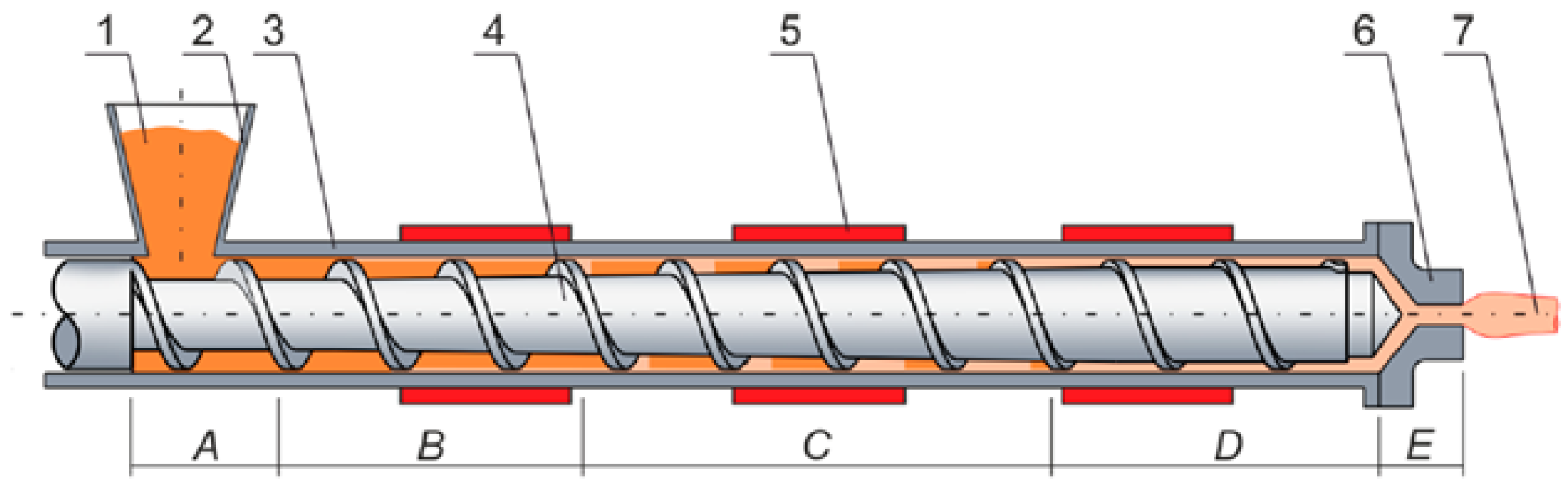
2.1.1. Single-Screw
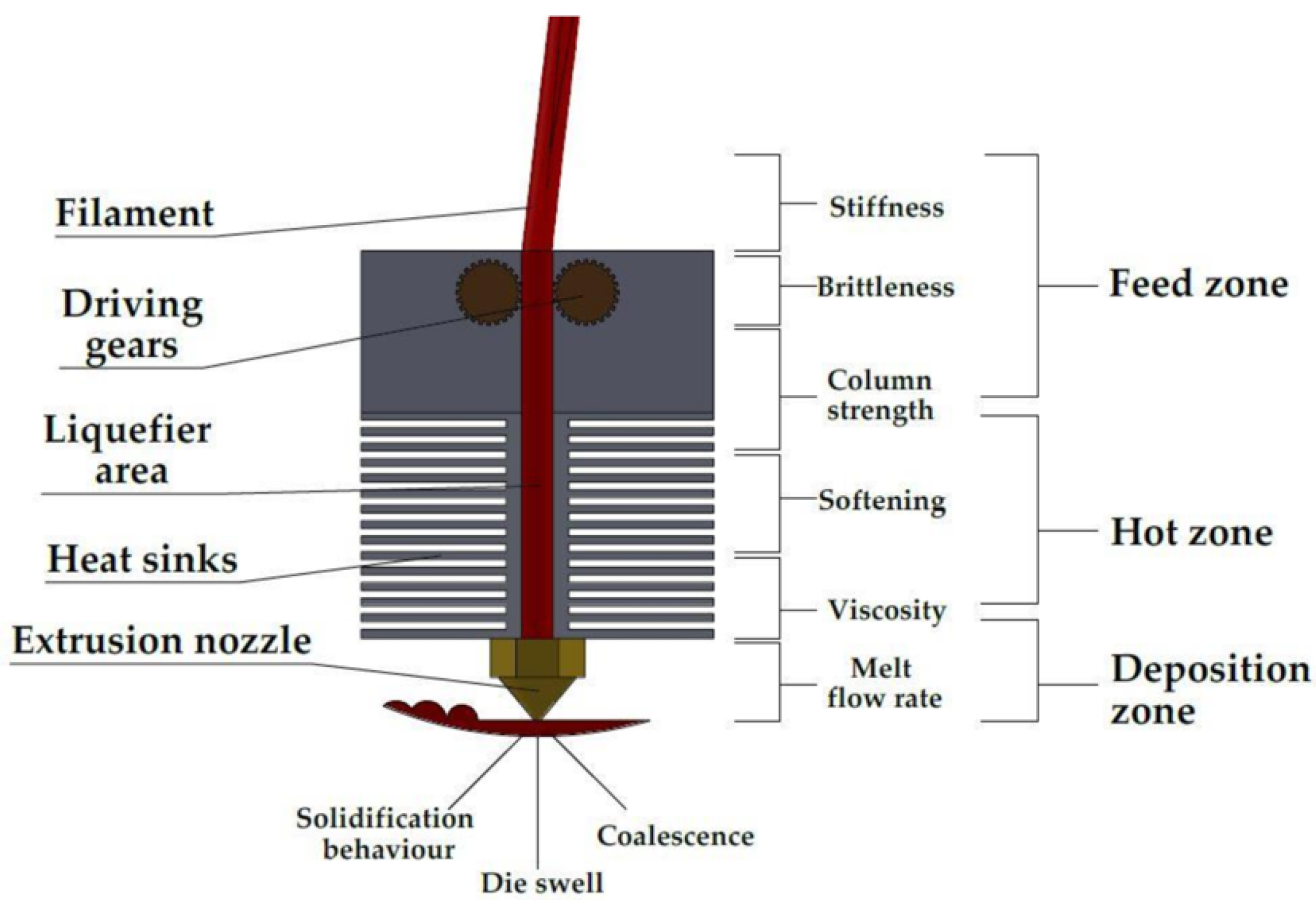
2.1.2. Filament Extruder
- Slippage causes loss of speed given byand can be induced by roundness deviation, wear or insufficient torque;
- Deformation occurs in the filament indentation as a result of the compression exerted by the roller teeth, which can cut into the filament.
- Direct: the motors are mounted directly on top of the liquefier. The load on the end-effector is higher, but the movement of the filament is more constrained and hence more controlled;
- Bowden: only the liquefier is mounted on the printing head, while the motors are placed in a fixed position of the machine, diminishing the load on the end-effector. However, the filament needs to cover some distance from the rollers to the liquefier, which may lead to bending and buckling.
- Filament advancement: when the feeding speed increases, the filament takes less time to cover the channel of the liquefier. At constant heat flow, the point along the liquefier in which the phase shift of the filament occurs (called transition point ) moves further towards the nozzle. In the extreme case, the filament does not melt completely and reaches the nozzle in the solid state.
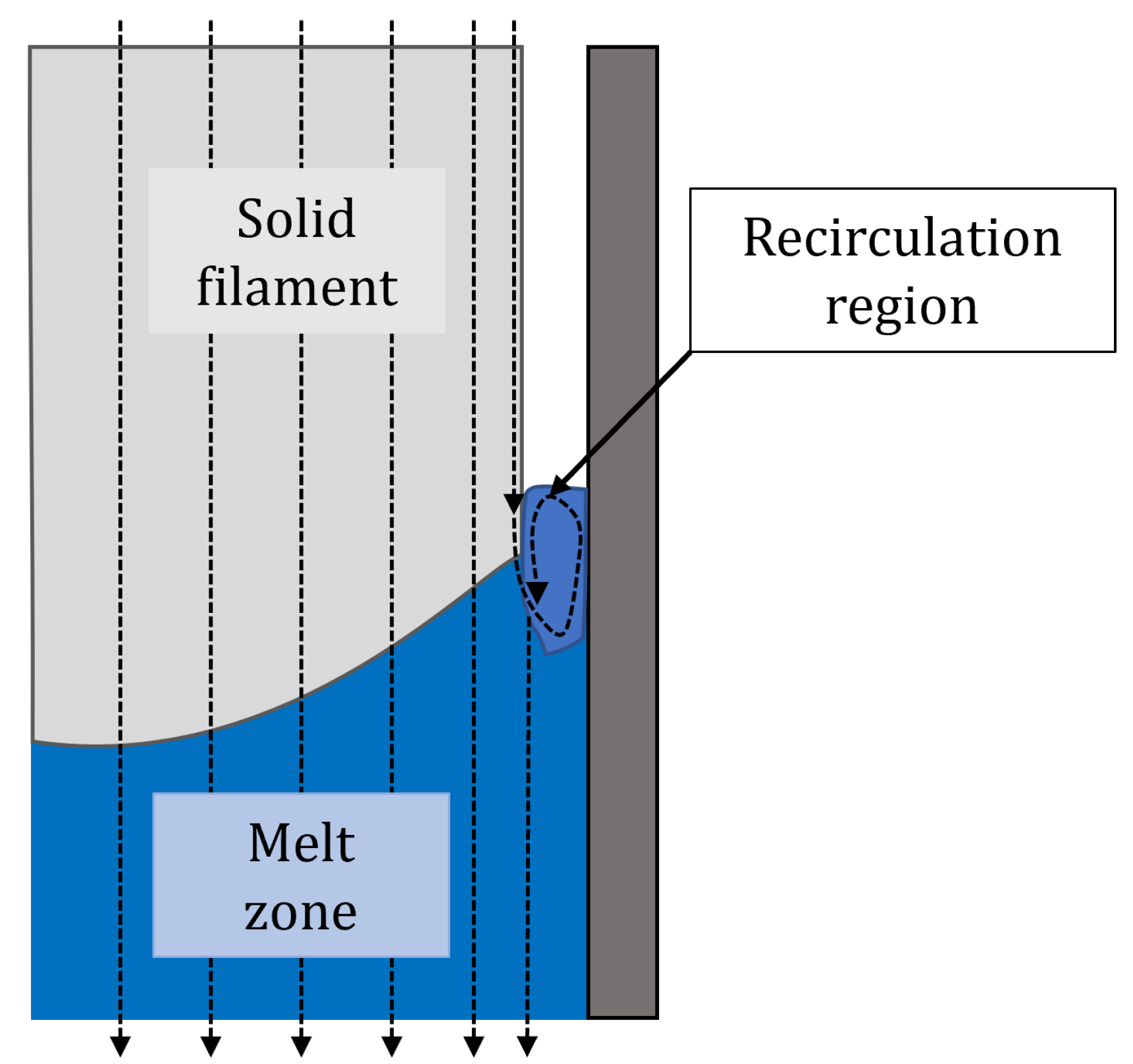
- Backflow: at the transition point, the liquid portion of the material partially fills the thin air layer that separates the solid filament from the channel wall (see Figure 3). This creates a region where a portion of the liquid flows in the opposite direction of the feeding speed and recirculates, reducing the shear stress in the liquefier and leading to a drop in the feeding force.
2.2. Deposition
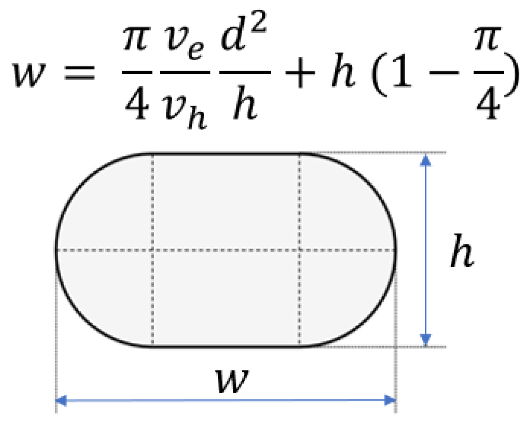
2.2.1. Strand Geometry
2.2.2. Surface Roughness
2.2.3. Global Structure
- can cause considerable distortions in new the layers;
- Smaller h and s lead to smaller porosity and better surface roughness.
3. Control
3.1. Offline
3.2. Online
3.2.1. Single-Screw
3.2.2. Filament Extruder
4. Conclusions
Author Contributions
Funding
Acknowledgments
Conflicts of Interest
References
- Bikas, H.; Stavropoulos, P.; Chryssolouris, G. Additive manufacturing methods and modelling approaches: A critical review. Int. J. Adv. Manuf. Technol. 2016, 83, 389–405. [Google Scholar] [CrossRef] [Green Version]
- Ligon, S.C.; Liska, R.; Stampfl, J.; Gurr, M.; Mulhaupt, R. Polymers for 3D printing and customized additive manufacturing. Chem. Rev. 2017, 117, 10212–10290. [Google Scholar] [CrossRef] [PubMed] [Green Version]
- Herzog, D.; Seyda, V.; Wycisk, E.; Emmelmann, C. Additive manufacturing of metals. Acta Mater. 2016, 117, 371–392. [Google Scholar] [CrossRef]
- Zocca, A.; Colombo, P.; Gomes, C.M.; Günster, J. Additive manufacturing of ceramics: Issues, potentialities, and opportunities. J. Am. Ceram. Soc. 2015, 98, 1983–2001. [Google Scholar] [CrossRef]
- Ngo, T.D.; Kashani, A.; Imbalzano, G.; Nguyen, K.T.; Hui, D. Additive manufacturing (3D printing): A review of materials, methods, applications and challenges. Compos. Part B Eng. 2018, 143, 172–196. [Google Scholar] [CrossRef]
- Sathies, T.; Senthil, P.; Anoop, M. A review on advancements in applications of fused deposition modelling process. Rapid Prototyp. J. 2020, 26, 669–687. [Google Scholar]
- Zhao, D.; Guo, W. Shape and performance controlled advanced design for additive manufacturing: A review of slicing and path planning. J. Manuf. Sci. Eng. 2020, 142, 010801. [Google Scholar] [CrossRef]
- Duty, C.; Ajinjeru, C.; Kishore, V.; Compton, B.; Hmeidat, N.; Chen, X.; Liu, P.; Hassen, A.A.; Lindahl, J.; Kunc, V. What makes a material printable? A viscoelastic model for extrusion-based 3D printing of polymers. J. Manuf. Process. 2018, 35, 526–537. [Google Scholar] [CrossRef]
- Mohamed, O.A.; Masood, S.H.; Bhowmik, J.L. Optimization of fused deposition modeling process parameters: A review of current research and future prospects. Adv. Manuf. 2015, 3, 42–53. [Google Scholar] [CrossRef]
- Mohamed, O.A.; Masood, S.H.; Bhowmik, J.L. Optimization of fused deposition modeling process parameters for dimensional accuracy using I-optimality criterion. Measurement 2016, 81, 174–196. [Google Scholar] [CrossRef]
- Kamani, K.; Donley, G.J.; Rogers, S.A. Unification of the Rheological Physics of Yield Stress Fluids. Phys. Rev. Lett. 2021, 126, 218002. [Google Scholar] [CrossRef]
- Phan, D.D.; Swain, Z.R.; Mackay, M.E. Rheological and heat transfer effects in fused filament fabrication. J. Rheol. 2018, 62, 1097–1107. [Google Scholar] [CrossRef]
- Wang, Z.; Smith, D.E. Rheology effects on predicted fiber orientation and elastic properties in large scale polymer composite additive manufacturing. J. Compos. Sci. 2018, 2, 10. [Google Scholar] [CrossRef] [Green Version]
- Coogan, T.J.; Kazmer, D.O. In-line rheological monitoring of fused deposition modeling. J. Rheol. 2019, 63, 141–155. [Google Scholar] [CrossRef]
- Faes, M.; Abbeloos, W.; Vogeler, F.; Valkenaers, H.; Coppens, K.; Goedeme, T.; Ferraris, E. Process monitoring of extrusion based 3D printing via laser scanning. arXiv 2016, arXiv:1612.02219. [Google Scholar]
- Ceruti, A.; Liverani, A.; Bombardi, T. Augmented vision and interactive monitoring in 3D printing process. Int. J. Interact. Des. Manuf. 2017, 11, 385–395. [Google Scholar] [CrossRef]
- Mikulionok, I.; Radchenko, L. Screw extrusion of thermoplastics: I. General model of the screw extrusion. Russ. J. Appl. Chem. 2012, 85, 489–504. [Google Scholar] [CrossRef]
- Tadmor, Z.; Broyer, E. Solids conveying in screw extruders Part II: Non isothermal model. Polym. Eng. Sci. 1972, 12, 378–386. [Google Scholar] [CrossRef]
- Broyer, E.; Tadmor, Z. Solids conveying in screw extruders Part I: A modified isothermal model. Polym. Eng. Sci. 1972, 12, 12–24. [Google Scholar] [CrossRef]
- Moysey, P.; Thompson, M. Investigation of solids transport in a single-screw extruder using a 3-D discrete particle simulation. Polym. Eng. Sci. 2004, 44, 2203–2215. [Google Scholar] [CrossRef]
- Moysey, P.; Thompson, M. Modelling the solids inflow and solids conveying of single-screw extruders using the discrete element method. Powder Technol. 2005, 153, 95–107. [Google Scholar] [CrossRef]
- Edmondson, I.; Fenner, R. Melting of thermoplastics in single screw extruders. Polymer 1975, 16, 49–56. [Google Scholar] [CrossRef]
- Lindt, J. A dynamic melting model for a single-screw extruder. Polym. Eng. Sci. 1976, 16, 284–291. [Google Scholar] [CrossRef]
- Cox, A.; Fenner, R. Melting performance in the single screw extrusion of thermoplastics. Polym. Eng. Sci. 1980, 20, 562–571. [Google Scholar] [CrossRef]
- Elbirli, B.; Lindt, J.; Gottgetreu, S.; Baba, S. Mathematical modeling of melting of polymers in a single-screw extruder. Polym. Eng. Sci. 1984, 24, 988–999. [Google Scholar] [CrossRef]
- Marschik, C.; Roland, W.; Miethlinger, J. A network-theory-based comparative study of melt-conveying models in single-screw extrusion: A. isothermal flow. Polymers 2018, 10, 929. [Google Scholar] [CrossRef] [PubMed] [Green Version]
- Pachner, S.; Loew-Baselli, B.; Affenzeller, M.; Miethlinger, J. A Generalized 2D output model of polymer melt flow in single-screw extrusion. Int. Polym. Process. 2017, 32, 209–216. [Google Scholar] [CrossRef]
- Marschik, C.; Roland, W.; Löw-Baselli, B.; Miethlinger, J. A heuristic method for modeling three-dimensional non-Newtonian flows of polymer melts in single-screw extruders. J. Non-Newton. Fluid Mech. 2017, 248, 27–39. [Google Scholar] [CrossRef]
- Polychronopoulos, N.; Vlachopoulos, J. Computer flow simulation of moffatt eddies in single screw extrusion. Int. Polym. Process. 2018, 33, 662–668. [Google Scholar] [CrossRef]
- Wilczynski, K.; Nastaj, A.; Lewandowski, A.; Wilczynski, K.J.; Buziak, K. Fundamentals of global modeling for polymer extrusion. Polymers 2019, 11, 2106. [Google Scholar] [CrossRef] [Green Version]
- Wilczynski, K.; Lewandowski, A.; Wilczynski, K.J. Experimental study for starve-fed single screw extrusion of thermoplastics. Polym. Eng. Sci. 2012, 52, 1258–1270. [Google Scholar] [CrossRef]
- Dey, A.; Roan Eagle, I.N.; Yodo, N. A review on filament materials for fused filament fabrication. J. Manuf. Mater. Process. 2021, 5, 69. [Google Scholar] [CrossRef]
- Fuenmayor, E.; Forde, M.; Healy, A.V.; Devine, D.M.; Lyons, J.G.; McConville, C.; Major, I. Material considerations for fused-filament fabrication of solid dosage forms. Pharmaceutics 2018, 10, 44. [Google Scholar] [CrossRef] [Green Version]
- Greeff, G.P.; Schilling, M. Closed loop control of slippage during filament transport in molten material extrusion. Addit. Manuf. 2017, 14, 31–38. [Google Scholar] [CrossRef]
- Bellini, A.; Guçeri, S.; Bertoldi, M. Liquefier dynamics in fused deposition. J. Manuf. Sci. Eng. 2004, 126, 237–246. [Google Scholar] [CrossRef]
- Go, J.; Schiffres, S.N.; Stevens, A.G.; Hart, A.J. Rate limits of additive manufacturing by fused filament fabrication and guidelines for high-throughput system design. Addit. Manuf. 2017, 16, 1–11. [Google Scholar] [CrossRef]
- Serdeczny, M.P.; Comminal, R.; Mollah, M.T.; Pedersen, D.B.; Spangenberg, J. Numerical modeling of the polymer flow through the hot-end in filament-based material extrusion additive manufacturing. Addit. Manuf. 2020, 36, 101454. [Google Scholar] [CrossRef]
- Jin, Y.z.; Zhang, J.f.; Wang, Y.; Zhu, Z.c. Filament geometrical model and nozzle trajectory analysis in the fused deposition modeling process. J. Zhejiang Univ.-Sci. A 2009, 10, 370–376. [Google Scholar] [CrossRef]
- Comminal, R.; Serdeczny, M.P.; Pedersen, D.B.; Spangenberg, J. Numerical modeling of the strand deposition flow in extrusion-based additive manufacturing. Addit. Manuf. 2018, 20, 68–76. [Google Scholar] [CrossRef] [Green Version]
- Serdeczny, M.P.; Comminal, R.; Pedersen, D.B.; Spangenberg, J. Experimental validation of a numerical model for the strand shape in material extrusion additive manufacturing. Addit. Manuf. 2018, 24, 145–153. [Google Scholar] [CrossRef]
- Agassant, J.F.; Pigeonneau, F.; Sardo, L.; Vincent, M. Flow analysis of the polymer spreading during extrusion additive manufacturing. Addit. Manuf. 2019, 29, 100794. [Google Scholar] [CrossRef] [Green Version]
- Chesser, P.; Post, B.; Roschli, A.; Carnal, C.; Lind, R.; Borish, M.; Love, L. Extrusion control for high quality printing on Big Area Additive Manufacturing (BAAM) systems. Addit. Manuf. 2019, 28, 445–455. [Google Scholar] [CrossRef]
- Ahn, D.; Kweon, J.H.; Kwon, S.; Song, J.; Lee, S. Representation of surface roughness in fused deposition modeling. J. Mater. Process. Technol. 2009, 209, 5593–5600. [Google Scholar] [CrossRef]
- Rahmati, S.; Vahabli, E. Evaluation of analytical modeling for improvement of surface roughness of FDM test part using measurement results. Int. J. Adv. Manuf. Technol. 2015, 79, 823–829. [Google Scholar] [CrossRef]
- Taufik, M.; Jain, P.K. A study of build edge profile for prediction of surface roughness in fused deposition modeling. J. Manuf. Sci. Eng. 2016, 138, 061002. [Google Scholar] [CrossRef]
- Coogan, T.J.; Kazmer, D.O. Prediction of interlayer strength in material extrusion additive manufacturing. Addit. Manuf. 2020, 35, 101368. [Google Scholar] [CrossRef]
- Serdeczny, M.P.; Comminal, R.; Pedersen, D.B.; Spangenberg, J. Numerical simulations of the mesostructure formation in material extrusion additive manufacturing. Addit. Manuf. 2019, 28, 419–429. [Google Scholar] [CrossRef]
- Thrimurthulu, K.; Pandey, P.M.; Reddy, N.V. Optimum part deposition orientation in fused deposition modeling. Int. J. Mach. Tools Manuf. 2004, 44, 585–594. [Google Scholar] [CrossRef]
- Jiang, J.; Ma, Y. Path planning strategies to optimize accuracy, quality, build time and material use in additive manufacturing: A review. Micromachines 2020, 11, 633. [Google Scholar] [CrossRef]
- Han, W.; Jafari, M.A.; Danforth, S.C.; Safari, A. Tool path-based deposition planning in fused deposition processes. J. Manuf. Sci. Eng. 2002, 124, 462–472. [Google Scholar] [CrossRef]
- Comminal, R.; Serdeczny, M.P.; Pedersen, D.B.; Spangenberg, J. Motion planning and numerical simulation of material deposition at corners in extrusion additive manufacturing. Addit. Manuf. 2019, 29, 100753. [Google Scholar] [CrossRef]
- Abeykoon, C. Single screw extrusion control: A comprehensive review and directions for improvements. Control. Eng. Pract. 2016, 51, 69–80. [Google Scholar] [CrossRef] [Green Version]
- Fingerle, D. Autogenic melt temperature control system for plastic extrusion. J. Elastomers Plast. 1978, 10, 293–310. [Google Scholar] [CrossRef]
- Parnaby, J.; Kochhar, A.K.; Wood, B. Development of computer control strategies for plastic extruders. Polym. Eng. Sci. 1975, 15, 594–605. [Google Scholar] [CrossRef]
- Kochhar, A.; Parnaby, J. Dynamical modelling and control of plastics extrusion processes. Automatica 1977, 13, 177–183. [Google Scholar] [CrossRef]
- Costin, M.; Taylor, P.; Wright, J. On the dynamics and control of a plasticating extruder. Polym. Eng. Sci. 1982, 22, 1095–1106. [Google Scholar] [CrossRef]
- Previdi, F.; Savaresi, S.M.; Panarotto, A. Design of a feedback control system for real-time control of flow in a single-screw extruder. Control Eng. Pract. 2006, 14, 1111–1121. [Google Scholar] [CrossRef]
- Chiu, S.H.; Lin, C.C. Applying the constrained minimum variance control theory on in-line viscosity control in the extrusion molding process. J. Polym. Res. 1998, 5, 171–175. [Google Scholar] [CrossRef]
- Jang, J.S.R.; Sun, C.T.; Mizutani, E. Neuro-fuzzy and soft computing-a computational approach to learning and machine intelligence [Book Review]. IEEE Trans. Autom. Control 1997, 42, 1482–1484. [Google Scholar] [CrossRef]
- Zheng, Q.; Gao, Z. An energy saving, factory-validated disturbance decoupling control design for extrusion processes. In Proceedings of the 10th World Congress on Intelligent Control and Automation, Beijing, China, 6–8 July 2012; pp. 2891–2896. [Google Scholar]
- Han, W.; Jafari, M.A. Coordination control of positioning and deposition in layered manufacturing. IEEE Trans. Ind. Electron. 2007, 54, 651–659. [Google Scholar] [CrossRef]
- Ertay, D.S.; Yuen, A.; Altintas, Y. Synchronized material deposition rate control with path velocity on fused filament fabrication machines. Addit. Manuf. 2018, 19, 205–213. [Google Scholar] [CrossRef] [Green Version]
- Terzi, E.; Bonassi, F.; Farina, M.; Scattolini, R. Learning model predictive control with long short-term memory networks. Int. J. Robust Nonlinear Control 2021, 18, 8877–8896. [Google Scholar] [CrossRef]
- Bonassi, F.; Scattolini, R. Recurrent neural network-based Internal Model Control of unknown nonlinear stable systems. arXiv 2021, arXiv:2108.04585. [Google Scholar]


Publisher’s Note: MDPI stays neutral with regard to jurisdictional claims in published maps and institutional affiliations. |
© 2022 by the authors. Licensee MDPI, Basel, Switzerland. This article is an open access article distributed under the terms and conditions of the Creative Commons Attribution (CC BY) license (https://creativecommons.org/licenses/by/4.0/).
Share and Cite
Martini, M.; Scaccia, M.; Marchello, G.; Abidi, H.; D’Imperio, M.; Cannella, F. An Outline of Fused Deposition Modeling: System Models and Control Strategies. Appl. Sci. 2022, 12, 5400. https://doi.org/10.3390/app12115400
Martini M, Scaccia M, Marchello G, Abidi H, D’Imperio M, Cannella F. An Outline of Fused Deposition Modeling: System Models and Control Strategies. Applied Sciences. 2022; 12(11):5400. https://doi.org/10.3390/app12115400
Chicago/Turabian StyleMartini, Michele, Massimiliano Scaccia, Gabriele Marchello, Haider Abidi, Mariapaola D’Imperio, and Ferdinando Cannella. 2022. "An Outline of Fused Deposition Modeling: System Models and Control Strategies" Applied Sciences 12, no. 11: 5400. https://doi.org/10.3390/app12115400