Article

Research on Creep Test of Compacted Graphite Cast Iron and Parameter Identification of Constitutive Model under Wide Range of Temperature and Stress

1
School of Mechanical Engineering, Hebei University of Technology, Tianjin 300401, China
2
Tianjin Key Laboratory of Power Transmission and Safety Technology for New Energy Vehicles, Tianjin 300400, China
3
National Key Laboratory of Diesel Engine Turbocharging Technology, China North Engine Research Institute, Tianjin 300400, China
*
Author to whom correspondence should be addressed.
Appl. Sci. 2022, 12(10), 5032; https://doi.org/10.3390/app12105032
Submission received: 5 March 2022 / Revised: 9 May 2022 / Accepted: 13 May 2022 / Published: 16 May 2022
(This article belongs to the Special Issue Fracture, Fatigue and Creep of Advanced Materials)

Abstract

:
With the increase in engine power density, the temperature and stress carried by the cylinder head during operation also increase. The thermal engine fatigue life prediction of the cylinder head needs to consider accurate and reasonable creep-constitutive models and parameters. In view of the wide range of temperature and stress working conditions of the compacted graphite cast iron (CGI) cylinder head, the creep test of CGI under the conditions of temperature 450~550 °C and stress 100~300 MPa was carried out, and CGI under the conditions of wide temperature and stress was proposed to characterize a creep-constitutive model for minimum creep rate. Research indicated that under wide temperature and stress conditions, CGI was more prone to creep damage than under low load, and creep deformation was dominated by grain boundary sliding (GBS), intragranular dislocation glide (IDG), and dislocation climb (IDC). With the deformation mechanism-based true stress (DMTS) creep model, combined with the multiobjective optimization method, a creep-constitutive model of CGI was constructed, and 73% of the predicted values of the model were within twice the error range. Compared with the linear regression method, the multiobjective optimization method could still fit the accurate model parameters in the case of small samples.

1. Introduction

As automobile designs pay more and more attention to lightweight, fuel economy, and exhaust emissions, compacted graphite cast iron (CGI) is widely used in engine cylinder blocks and cylinder heads because of its excellent mechanical properties and material properties [1,2,3]. However, because of the continuous development of the engine in the direction of high power, the working environment of the engine is becoming worse and worse [4,5]. For example, the maximum working temperature of the CGI cylinder head has been raised to above 430 °C, and the nose bridge area between the intake and exhaust valves was subjected to a large range of mechanical loads of 100 to 320 MPa [6]. Generally, the creep damage to the cylinder head occurred in a working environment of high temperature and high stress [7]. However, with the continuous increase in the maximum load and maximum temperature, the stress and temperature range under all working conditions continue to expand. Even if the CGI cylinder head works in an environment of high temperature and low stress or low temperature and high stress for a long time, creep damage will occur. So, as creep is one of the main reasons for the cracking of the CGI cylinder head [8], research on fatigue reliability of engine cylinder heads must consider the effect of creep damage [9,10,11,12].
At present, many scholars have carried out much work on the creep behavior of commonly used materials [13,14,15,16,17]. However, most of them have only carried out creep tests under a small temperature and stress range. Hence, the application range of the conclusions has certain limitations as it is not suitable for parts with a wide range of working conditions, such as engines, and cannot completely express the creep behavior of the engine under full operating conditions; thus, predicted creep damage will be conservative. For the working environment of the engine, this paper defines the temperature range greater than 80 °C and the stress range greater than 150 MPa as a wide temperature and stress range. Therefore, it has a certain engineering background and practical significance for studying the creep properties of vermicular graphite iron under wide temperature and stress conditions.
Since CGI has been widely used, many scholars have carried research on its material properties and creep behavior [18,19,20,21]. However, the research on the minimum creep rate of CGI is often neglected. As an important index to measure the creep performance of the material, it is necessary to study the effect of creep aging conditions on the minimum creep rate. In studying the minimum creep rate of materials, most scholars currently use the linear regression method to fit the parameters of the creep-constitutive model. Based on the hyperbolic sine function equation, Liu et al. established the constitutive model correlation between the minimum creep rate of 2219 aluminum alloy and the test stress and temperature by carrying out creep tests under the conditions of 80~185 °C and 130~173 MPa [22]. Dehler et al. studied the creep behavior of die-casting ALSiCu4-T6 alloy cylinder head, carried out creep tests under the conditions of 222~272 °C and 72~213 MPa, obtained the minimum creep rate under each condition, and obtained the Monkman–Grant relation that the model can accurately predict creep life only at elevated temperatures [7]. Ye and Hu et al. studied the creep behavior of TC11 titanium alloy at 558~675 MPa at 500 °C and obtained a new constitutive model describing the whole creep process [23]. It can be seen from the above literature that the calculation procedure of the linear regression method is cumbersome, and its calculation process is not the same for different models. In addition, when the data points of the creep test are few, using the linear regression method will cause the fitted model parameters to be inaccurate or even unable to fit the parameters, so the linear regression method has certain shortcomings in the application. Eisenträger, Naumenko, and Altenbach believed that a unified constitutive model should be calibrated for a wide range of strain rates, stress, and temperatures, but for materials such as cast iron, the functions of material parameters, strain rate, stress, and temperature needed to be identified. Therefore, they proposed a method of step-by-step identification procedure, using the optimization function to calibrate the model to determine all the parameters, which provided researchers with a new idea [24,25]. The multiobjective optimization method has matured in recent years and has been gradually applied to engineering practice [26]. Using the multiobjective optimization method to fit model parameters has no limit to the range or number of fitted data points and has the advantages of fast calculation speed and accurate results [27,28,29], so this method can accurately obtain the creep-constitutive model parameters of CGI under wide temperature and stress range in most cases.
In this paper, according to the actual working conditions of the dangerous area, such as the nose bridge area between the intake and exhaust ports of the diesel engine CGI cylinder head, the uniaxial tensile creep test was carried out under the high temperatures of 450 °C, 500 °C, and 550 °C and the stress of 100~300 MPa. The creep behavior of CGI was studied, and the effects of different test temperatures and test stresses on its minimum creep rate were analyzed. Then, using the deformation mechanism-based true stress (DMTS) creep model [30] and the multiobjective multivariable model parameter-optimization technique, a creep-constitutive model of CGI describing a wide temperature and stress range was established. The application range of the model was close to the working conditions of the engine cylinder head, supercharger housing, and other components, which provided a theoretical basis for predicting the creep performance of vermicular graphite iron materials and laid a foundation for the thermal engine fatigue analysis of cylinder heads and other components. By analyzing and comparing the linear regression method and the multiobjective optimization method, it was verified that the multiobjective optimization method could solve the problem of fitting accurate parameters with small samples.

2. Experimental Procedures

2.1. Casting Conditions for Compacted Graphite Iron Cylinder Heads

The test selected a certain type of diesel engine CGI cylinder head as the research object. The main chemical composition of cast iron is shown in Table 1. The alloy liquid was smelted with a GGW-0.012 medium-frequency induction furnace, the addition amount of vermicularizer was 0.45%, the addition amount of inoculant was 0.8%, and the addition amount of secondary inoculant was 0.4%. When the furnace temperature rose to 1450 °C, the molten iron, after creeping and inoculation treatment, was poured into the clay sand mold. After solidification, heat treatment at 900 °C for 110 min, water quenching, and 500 °C for 0–90 h was performed to simulate the high-temperature service conditions of the cylinder head. The cylinder head after casting is shown in Figure 1. Quanta 600 scanning electron microscope was used to observe the microstructure of the surface of the CGI cylinder head after casting. The carbon equivalent of CGI in this paper was 4.5 (CE = C% + 1/3 (Si% + P%)), so its melting point was approximately 1154 °C.

2.2. Tensile Test of Compacted Graphite Cast Iron

Tensile tests were carried out in accordance with “GB/T 228.1-2010 Tensile Test of Metallic Materials Part 1: Test Method at Room Temperature” and “GB/T 228.2-2015 Tensile Test of Metallic Materials Part 2: High Temperature Test Method”. The sampling position is shown in Figure 1; the tensile specimen was cut between the valves on the fire surface of the cylinder head. The test used a dog-bone tensile specimen with a diameter of 5 mm and a gauge length of 25 mm. Tensile tests were performed using a hydraulic servo tensile testing machine (MTS 370) at a test strain rate of 0.0001 s−1.
In this paper, the ultimate tensile strength (UTS) of CGI was tested at 23 °C, 200 °C, 300 °C, 400 °C, 450 °C, and 550 °C. Six samples were tested at each temperature, and the average values of the six samples were 455 MPa, 517 MPa, 480 MPa, 425 MPa, 340 MPa, and 236 MPa, respectively. The curve of the tensile properties of CGI as a function of temperature was obtained by cubic polynomial fitting (as shown in Figure 2a), and the coefficient of determination (R2) of the fitted curve was 0.9889. It can be seen that the UTS of CGI was significantly affected by temperature, and the UTS showed a trend of first rising and then decreasing in the range of 23~550 °C and reaching a maximum value within 100~200 °C. According to the engineering stress–strain curves of 6 samples at each temperature, the true stress–strain curves at different temperatures were obtained by fitting (as shown in Figure 2b). It can be seen that there was no obvious yield point for the samples at different temperatures, and the work hardening ability at 200 °C and 300 °C was improved compared with room temperature. The tensile properties of CGI at different temperatures in this paper were similar to the research conclusions of the literature [18].

2.3. Creep Test of Compacted Graphite Cast Iron

According to “GB/T 2039-2012 Uniaxial Tensile Creep Test Method for Metallic Materials”, the creep test of CGI was carried out. The testing instruments were the RD-50 metal high-temperature creep and durability testing machine, RJ-30D metal high-temperature tensile creep and durability testing machine, and CSS-3905 high-temperature electronic creep durability testing machine. The sampling position of the test was the same as that of the tensile test (as shown in Figure 1). The creep test was carried out using a dog-bone tensile specimen with a diameter of 5 mm and a gauge length of 25 mm. The specific dimensions of the specimen are shown in Figure 3 below. The deformation of the sample was measured with a HEIDENHAIN grating-scale deformation sensor with an accuracy grade of ±2 μm.
Because the area of the diesel engine cylinder head that was easy to crack and fail in this paper was the bridge zone between the exhaust valves and exhaust-inlet valve bridge, its maximum working temperature was around 490 °C, and the mechanical load it carried varied from 100 to 320 MPa. Thus, a wide range of conditions with a temperature of 450~550 °C and stress of 100~300 MPa was selected as the load range of the creep test, and the test loads corresponding to 3 temperatures and 5 stress levels were selected. The creep test load points are shown in Table 2. The electric furnace adopted a three-stage heating method. When heating up, an initial load of 200 N was applied to the sample to ensure that the sample was loaded coaxially. After heating to the target temperature, the temperature was kept for 1 h, and then the load was applied to the target load. In order to reduce the measurement error, two displacement gauges were placed on the steps of the sample to measure the deformation and displacement on the left and right sides of the sample, respectively. Then the average values were taken to obtain the deformation and displacement values of the sample. During the test, the fluctuations of the test force and temperature were controlled at ±1 N and ±1 °C, respectively, and the test time, the left and right deformation and displacement of the sample were recorded every minute.

3. Results and Discussion

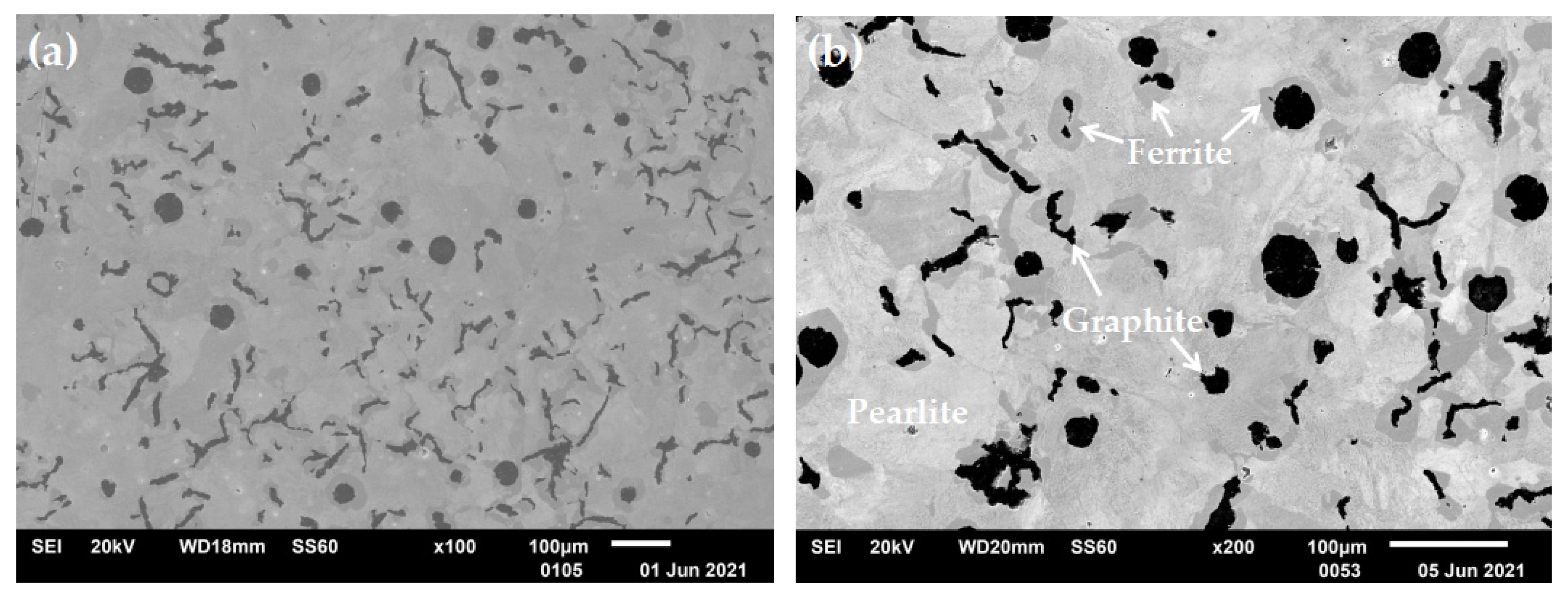
3.1. Microstructure of Compacted Graphite Iron

The microstructure of compacted graphite iron is shown in Figure 4. Figure 4a is an image observed at a magnification of 100 times. It can be observed that most of the graphite in CGI existed in isolation and was mainly vermicular, with a small amount of spheroidal graphite and agglomerate graphite in the middle. Figure 4b is a 200× magnification of the microstructure image. It can be seen that the matrix of vermicular graphite iron was composed of ferrite and pearlite, of which the gray area was ferrite, mainly distributed around the graphite. The bright white area was pearlite, which was distributed in a lamellar aggregation state, and the distribution was uneven.

3.2. Creep Properties of Compacted Graphite Cast Iron

Figure 5a–c are the creep curves of CGI at the test temperatures of 450 °C, 500 °C, and 550 °C, respectively. Evidently, its creep deformations were related to three factors: test stress, creep time, and test temperature and all three were positively correlated. In addition, the creep curves under different test conditions were very different. At 450 °C and 200 MPa, 500 °C and 150 MPa, and 550 °C and 100 MPa, the deformation of the CGI sample continued for 100 h without breaking. The rest of the samples were deformed to fracture within 0~70 h. The reason for this phenomenon was related to the use of a wide range of stress and temperature test conditions.
It can be observed in Figure 5 that CGI was quite prone to creep damage under a wide range of temperature and stress test conditions. As shown in Figure 5c, under the condition that the test temperature was 550 °C and the test stress was 100 MPa, when the sample reached 100 h test time, its creep deformation was 2.22%. As shown in Figure 5a, under the conditions of the test temperature of 450 °C and the test stress of 275 MPa, the creep deformation of the specimen when it reaches fracture was 3.21%, and the total creep time was 2.8 h. It can be seen that the creep deformation under high temperature and low stress and low temperature and high-stress conditions was smaller than that under high temperature and high-stress conditions, but with the increase in test time, it would also produce creep damage and cause a fracture.
According to the change in creep rate, the creep curve will go through three stages in sequence: the first creep stage, the second creep stage, and the third creep stage [31]. The second stage of each creep curve in Figure 5 was linearly fitted to obtain the minimum creep rate under different test conditions, as shown in Table 3, and its value was related to the test temperature and test stress. At 500 °C, the minimum creep rate of the sample at 200 MPa was 0.618 × 10² h−1, and the minimum creep rate of the sample at 225 MPa reached 2.097 × 10⁻² h−1. Similarly, under the test stress condition of 200 MPa, when the test temperature was increased from 500 °C to 550 °C, the minimum creep rate was accelerated from 0.618 × 10² h−1 to 7.110 2 × 10⁻² h−1. It can be seen that the minimum creep rate of CGI increased with the increase in stress and temperature, which was consistent with the findings in [21]. In addition, at 500 °C, the stress increased by 12.5% from 200 MPa to 225 MPa, and the corresponding minimum creep rate increased by 239.3%. However, under the stress condition of 200 MPa, the temperature increased by 10.0% from 500 °C to 550 °C, and the corresponding minimum creep rate increased by 1050.5%. It can be seen that the effect of temperature on the minimum creep rate was greater than that of stress.
It can be seen in Table 3 that when the temperature was 550 °C and the stress was 100 MPa, the minimum creep rate of the sample was 1.8968 × 10⁻⁴ h−1. When the temperature was 450 °C, and the stress was 275 MPa, the minimum creep rate of the sample was 7.855 × 10⁻³ h−1. Under the test conditions of high temperature and low stress and low temperature and high stress, the creep rate of CGI was relatively small, but with the increase in creep time, the creep deformation of the sample was also very considerable. Therefore, with the increase in the working load range of the CGI cylinder head, the creep would have a more and more obvious effect on its cracking.

3.3. Deformation Mechanism-Based True Stress Creep Model

The second stage of creep accounts for most of the creep life, and the minimum creep rate is a key indicator to characterize the creep characteristics of materials. Therefore, the second creep stage is also studied in practical engineering. When studying minimum creep rates over a wide range of stresses, both linear and power-law creep must be considered, and the secondary creep model must be extended by introducing appropriate Arrhenius-type temperature functions and internal state variables to account for temperature dependence and microstructural degradation processes, such as subgrain coarsening and creep cavitation [32]. Over a wide range of stress and temperatures, creep is usually caused by a variety of mechanisms, including intragranular dislocation glide (IDG), intragranular dislocation climb (IDC), and grain boundary sliding (GBS). Therefore, the creep-constitutive model of CGI should be established based on the creep deformation mechanism to facilitate the study of the effects of different physical mechanisms on its creep.
To date, the DMTS creep model has been proposed, it has performed well over a wide range of stresses, and it has been well applied under the conditions of wide stress and temperature range of Waspaloy alloy, modified P91 steel, G115 steel, and SA508 Gr.3 alloy [30,33,34,35]. The derivation process of the CGI creep-constitutive model based on the DMTS creep model is as follows:
The relationship between the minimum creep rate and the stress is usually expressed by the Norton–Bailey power law equation, as shown in the following Equation (1):
ε ˙ = K σ n
where ε ˙ is the minimum creep rate (h−1), σ is the stress level (MPa), and K and n are material-dependent constants. Therefore, according to Equation (1), the minimum creep rates under the action mechanisms of GBS, IDG, and IDC can be expressed as:
  ε ˙ s = A 0 exp ( Q A R T ) σ p
ε ˙ g = B 0 exp ( Q B R T ) σ n
ε ˙ c = C 0 exp ( Q C R T ) σ m
where ε ˙ s , ε ˙ g , and ε ˙ c are the minimum creep rates of GBS, IDG, and IDC, respectively, QA, QB, and QC are the activation energies (J/Mol) of GBS, IDG, and IDC, respectively, p, n, and m are the stress exponents of GBS, IDG, and IDC mechanisms, respectively; A0, B0, and C0 are proportional constants, R is the gas constant with a value of 8.314 J·mol−1·K−1, and T is the thermodynamic temperature (K). Therefore, the total creep rate caused by these mechanisms of action can be expressed by the following Equation (5):
ε ˙ = ε ˙ s + ε ˙ g + ε ˙ c  
Figure 6 shows the relationship between the minimum creep rate and stress of CGI at different temperatures in the double logarithmic coordinate system. Three power exponent regions could be obtained by linear fitting. Combining them with the material deformation mechanism maps [36], it could be seen that in the high-stress region (250~300 MPa) of 450 °C and the high-stress region (225~275 MPa) of 500 °C, the creep rate behavior had a constant power exponent, and the creep deformation was mainly caused by IDG. In the low-stress region (200~250 MPa) at 450 °C, the low-stress region (150~225 MPa) at 500 °C, and the high-stress region (175~225 MPa) at 550 °C, the creep behavior was dominated by GBS. In the low-stress region (100~175 MPa) at 550 °C, the creep of CGI was dominated by IDC. It can be seen that for each creep mechanism, the minimum creep rate of CGI exhibited a linear dependence on the stress on the logarithmic scale.
Generally, according to Figure 6 and in combination with Equations (2) to (3), the parameters A0, B0, C0, QA, QB, QC, p, n, and m can be determined by linear regression on the Arrhenius plots. However, in the region dominated by IDC, there was only the minimum creep rate corresponding to the low-stress region of 550 °C, so the parameters C0 and QC could not be obtained by linear regression fitting in this study. Therefore, the multiobjective optimization method was considered in this paper to obtain the parameters of the creep model.

3.4. Fitting of Model Parameters

Multiobjective optimization is multiobjective function optimization. Using this method to obtain the parameter values to be solved is one of the engineering applications of multiobjective optimization. According to the built optimization function, it can quickly fit the optimal solution of each parameter in the target equation, and it has good applicability even under the condition of small samples [37]. Therefore, the multiobjective and multivariable optimization technique can solve the problem of insufficient data points under the IDC mechanism in this paper. The predicted life values under the same test boundary are compared with the test results, and finally, the optimal model parameter values can be obtained.
The linear combination method is a branch of the evaluation function method, which belongs to the preference-based multiobjective optimization method [38]. This method can turn multiobjective optimization problems into single-objective ones, so it has the advantages of simple structure and efficient optimization, but the search preference determined in advance will directly affect the optimal solution [39,40]. The weight of each data point in the creep test of CGI is equal, that is, the minimum creep rate under each test load point, the relative error between the test results and the model prediction results should be minimized, which just avoids the shortcomings of the linear combination method. Therefore, this paper adopted a relatively simple and commonly used linear combination method, and the general expression of its evaluation function was as follows:
    min U ( x ) = i = 1 p w i f i ( x ) x D R n D : g u ( x ) 0 h v ( x ) = 0 }
where wi is the weighting coefficient, which is used to assign the importance of each objective function, fi(x) is the subobjective function, Rn is an n-dimensional real Euclidean space, and gu(x) and hv(x) are constraints on design parameters.
In this problem, the subobjective function was set as the minimum value function of the relative error between the model predicted value and the experimental value of the minimum creep rate under each test condition. The design parameters were activation energies QA, QB, and QC, stress exponents p, n, and m, and proportionality constants A0, B0, and C0. According to experience, the optimization interval Dj of each design parameter xj was determined, that was, the constraint condition of the design parameter. The objective function constructed in combination with Formula (6) was the following formula:
    minf i ( x ) = w i | e i p i ( x ) e i |   ,     i = 1 , 2 , , 11
      s . t .                 x j D j     ,     j = 1 , 2 , 3 , 4
where ei is the experimental value of the minimum creep rate, and pi is the predicted value of the creep-constitutive model. The importance of each subobjective function is the same here, so the weight coefficient wi = 1/N, N is the number of data points.
The model parameter values obtained after multiobjective optimization are listed in Table 4. In order to verify the agreement between the model curve and the test data, according to the values in Table 4, the total minimum creep rate was calculated based on Equation (5). The predicted minimum creep rate stress curve of CGI was drawn into the same image as the test point (as shown in Figure 7a), and the comparison of the experimental value and the predicted value with twice the error band was plotted (as shown in Figure 7b). Since the creep time of CGI was very short under some conditions of high temperature and high stress, its minimum creep rate had a high sensitivity to the creep time. There was a certain error in the fitted minimum creep rate, which caused a large gap between the predicted value of individual points and the experimental value. However, in general, the model curve was in good agreement with most of the experimental results, with 73% of the data points within the double error band. The degree of dispersion between the predicted and experimental values was small. Consequently, it has been proved that the DMTS creep model can accurately describe the minimum creep rate of CGI under a wide range of temperatures and stress.
It can be seen that although the method of fitting the parameters of the creep-constitutive model by linear regression had been well used in the literature, the linear regression method was not suitable in the case of a few data points. It would cause one or some parameters to be unreasonable or even unable to fit the parameters so that the model could not accurately express the creep characteristics of CGI. In small samples, the multiobjective optimization method could still obtain more accurate parameters. In addition, by comparing the two methods of obtaining model parameters, it can be seen that the process of obtaining parameters through the multiobjective optimization method was more concise and efficient. As a consequence, the multiobjective and multivariable optimization technique has a certain significance in controlling research costs and improving model accuracy.

4. Conclusions

In this paper, the creep properties of CGI at the temperature of 450~550 °C and the stress level of 100~300 MPa were studied. Using the DMTS creep model, combined with a multiobjective optimization method, the minimum creep rate of CGI was predicted. The main conclusions are as follows:
  • At the temperature of 450~550 °C and the stress level of 100~300 MPa, the creep characteristics of CGI were related to the three factors of test stress, creep time, and test temperature. Compared with stress, the temperature had a greater impact on the creep damage of CGI. Therefore, priority can be given to improving the cooling performance of the engine cylinder head to reduce the temperature load to improve the reliability of the cylinder head and the engine;
  • According to the DMTS model, the creep deformation of CGI was mainly caused by three mechanisms: GBS, IDG, and IDC. At different stress and temperature ranges in this study, creep was dominated by different mechanisms. As a result, according to the application range of CGI, its microstructure can be adjusted reasonably to suppress the dominant creep deformation mechanism in this range, thereby prolonging the service life of CGI;
  • Under a wide range of temperature and stress, the DMTS creep model can reasonably express the minimum creep rate of CGI. Moreover, it has been proved that the multiobjective optimization method can solve the problem where the parameters cannot be fitted by the conventional linear regression method because of the small number of data points, so the method has good engineering practicability.

Author Contributions

Conceptualization, G.J.; methodology, G.J.; validation, J.W.; data curation, J.Z. and S.S.; writing—original draft preparation, S.L.; writing—review and editing, G.J. and G.C. All authors have read and agreed to the published version of the manuscript.

Funding

This research was funded by the National Key Laboratory of Science and Technology for National Defense, grant number 61422120301.

Institutional Review Board Statement

Not applicable.

Informed Consent Statement

Not applicable.

Data Availability Statement

The datasets supporting the conclusions of this article are included within the article.

Conflicts of Interest

The authors declare no conflict of interest.

References

  1. Guesser, W.L.; Duran, P.V.; Krause, W. Compacted graphite iron for diesel engine cylinder blocks. Congrès Le Diesel Aujourd’hui Et Demain Ec. Cent. 2004, 12–13. [Google Scholar]
  2. Dawson, S.; Hang, F. Compacted graphite iron-a material solution for modern diesel engine cylinder blocks and heads. China Foundry 2009, 6, 241–246. [Google Scholar]
  3. Essam, M.A.; Shash, A.Y.; Megahed, H.; El-Kashif, E. Effect of section thickness on microstructure and mechanical properties of compacted graphite iron for diesel engine application. Heliyon 2021, 7, e05930. [Google Scholar] [CrossRef] [PubMed]
  4. Hamm, T.; Rebbert, M.; Ecker, H.; Grafen, M. Cylinder head design for high peak firing pressures. SAE Int. J. Engines 2008, 1, 746–755. [Google Scholar] [CrossRef]
  5. Ren, P.-R.; Song, W.; Zhong, G.; Huang, W.-Q.; Zuo, Z.-X.; Zhao, C.-Z.; Yan, K.-J. High-cycle fatigue failure analysis of cast Al-Si alloy engine cylinder head. Eng. Fail. Anal. 2021, 127, 105546. [Google Scholar] [CrossRef]
  6. Jing, G.X.; Zhang, M.X.; Qu, S.; Pang, J.C.; Fu, C.M.; Dong, C.; Li, S.X.; Xu, C.G.; Zhang, Z.F. Investigation into diesel engine cylinder head failure. Eng. Fail. Anal. 2018, 90, 36–46. [Google Scholar] [CrossRef]
  7. Dehler, A.; Knirsch, S.; Srivastava, V.; Saage, H.; Heilmaier, M. Assessment of creep behaviour of the die-cast cylinder-head alloy AlSi6Cu4-T6. Int. J. Mater. Res. 2006, 97, 1679–1686. [Google Scholar] [CrossRef]
  8. Wang, Y.J.; Xu, Z.; Chen, M. Thermo-Mechanical Fatigue and life Prediction of Turbocharged Engine Cylinder Head; SAE Technical Paper; Report No.: 0148-7191; SAE International: Warrendale, PA, USA, 2020. [Google Scholar]
  9. Zhang, Q.; Zuo, Z.; Liu, J. Failure analysis of a diesel engine cylinder head based on finite element method. Eng. Fail Anal. 2013, 34, 51–58. [Google Scholar] [CrossRef]
  10. Guo, B.; Zhang, W.; Li, S.; Wang, X. High temperature low cycle fatigue and creep-fatigue behavior of a casting Al-9Si-CuMg alloy used for cylinder heads. Mater. Sci. Eng. A 2017, 700, 397–405. [Google Scholar] [CrossRef]
  11. Zhang, S.; Wang, Z.; Han, Y.; Zheng, Y.; Zhang, D. Experimental and theoretical studies on thermos-mechanical fatigue test for aluminium cast alloy. Fatigue Fract. Eng. Mater. Struct. 2020, 43, 110–118. [Google Scholar] [CrossRef]
  12. Farrahi, G.H.; Azadi, M.; Winter, G.; Eichlseder, W. A new energy-based isothermal and thermos-mechanical fatigue lifetime prediction model for aluminium–silicon–magnesium alloy. Fatigue Fract. Eng. Mater. Struct. 2013, 36, 1323–1335. [Google Scholar] [CrossRef]
  13. Ma, Y.; Xia, F.; Zhan, L.; Xu, Y. Study on Multi-Step Creep Aging Behavior of Al-Li-S4 Alloy. Metals 2019, 9, 807. [Google Scholar] [CrossRef] [Green Version]
  14. Zhang, J.; Deng, Y.; Zhang, X. Constitutive modeling for creep age forming of heat-treatable strengthening aluminum alloys containing plate or rod shaped precipitates. Mater. Sci. Eng. A 2013, 563, 8–15. [Google Scholar] [CrossRef]
  15. Dong, Y.; Ye, L.; Tang, J.; Liu, X.; Sun, Q. The effects of temperature on the creep-aging behavior and mechanical properties of AA2050-T34 alloy. Mater. Sci. Eng. A 2020, 796, 140010. [Google Scholar] [CrossRef]
  16. Lei, C.; Li, H.; Fu, J.; Shi, N.; Zheng, G.; Bian, T. Damage in creep aging process of an Al-Zn-Mg-Cu alloy: Experiments and modeling. Metals 2018, 8, 285. [Google Scholar] [CrossRef] [Green Version]
  17. Zhang, J.; Wang, B.; Wang, H.; Zhang, C. Improvement in compressive creep resistance of Al-0.2 Zr alloy with L12 structured Sc-enriched precipitates. Mater. Charact. 2020, 159, 110024. [Google Scholar] [CrossRef]
  18. Qiu, Y.; Pang, J.; Yang, E.; Li, S.; Zhang, Z. Transition of tensile strength and damaging mechanisms of compacted graphite iron with temperature. Mater. Sci. Eng. A 2016, 677, 290–301. [Google Scholar] [CrossRef]
  19. Qiu, Y.; Pang, J.; Li, S.; Yang, E.; Fu, W.; Liang, M.; Zhang, Z. Influence of thermal exposure on microstructure evolution and tensile fracture behaviors of compacted graphite iron. Mater. Sci. Eng. A 2016, 664, 75–85. [Google Scholar] [CrossRef]
  20. Ma, Z.; Tao, D.; Yang, Z.; Guo, Y.; Li, J.; Liang, M.; Yeung, L.T.L. The effect of vermicularity on the thermal conductivity of vermicular graphite cast iron. Mater. Des. 2016, 93, 418–422. [Google Scholar] [CrossRef]
  21. Wu, Y.; Li, J.P.; Yang, Z.; Guo, Y.; Ma, Z.; Liang, M.; Yang, T.; Tao, D. Creep Behavior of a High Strength Compacted Graphite Cast Iron. Chin. J. Mater. Res. 2019, 33, 43–52. [Google Scholar]
  22. Liu, L.; Zhan, L.; Li, W. Creep aging behavior characterization of 2219 aluminum alloy. Metals 2016, 6, 146. [Google Scholar] [CrossRef] [Green Version]
  23. Ye, W.; Hu, X.; Song, Y. A new creep model and its application in the evaluation of creep properties of a titanium alloy at 500 °C. J. Mech. Sci. Technol. 2020, 34, 2317–2326. [Google Scholar] [CrossRef]
  24. Eisenträger, J.; Naumenko, K.; Altenbach, H. Calibration of a phase mixture model for hardening and softening regimes in tempered martensitic steel over wide stress and temperature ranges. J. Strain Anal. Eng. Des. 2018, 53, 156–177. [Google Scholar] [CrossRef]
  25. Naumenko, K.; Holm, A. Modeling High Temperature Materials Behavior for Structural Analysis; Springer: Berlin/Heidelberg, Germany, 2016. [Google Scholar]
  26. Rangaiah, G.P. (Ed.) Multi-Objective Optimization: Techniques and Applications in Chemical Engineering; World Scientific: Singapore, 2016. [Google Scholar]
  27. Venkataraman, P. Applied Optimization with MATLAB Programming; John Wiley & Sons: Hoboken, NJ, USA, 2009. [Google Scholar]
  28. Marler, R.T.; Arora, J.S. Survey of multi-objective optimization methods for engineering. Struct. Multidiscip. Optim. 2004, 26, 369–395. [Google Scholar] [CrossRef]
  29. Wang, Q.; Liu, F.; Wang, X. Multi-objective optimization of machining parameters considering energy consumption. Int. J. Adv. Manuf. Technol. 2014, 71, 1133–1142. [Google Scholar] [CrossRef]
  30. Zhang, X.Z.; Wu, X.J.; Liu, R.; Yao, M.X. Deformation-mechanism-based modeling of creep behavior of modified 9Cr-1Mo steel. Mater. Sci. Eng. A 2017, 689, 345–352. [Google Scholar] [CrossRef]
  31. Evans, R.W.; Wilshire, B. Creep of Metals and Alloys; U.S. Department of Energy: Oak Ridge, TN, USA, 1985.
  32. Altenbach, H.; Gorash, Y.; Naumenko, K. Steady-state creep of a pressurized thick cylinder in both the linear and the power law ranges. Acta Mech. 2008, 195, 263–274. [Google Scholar] [CrossRef]
  33. Wu, X.J.; Williams, S.; Gong, D. A true-stress creep model based on deformation mechanisms for polycrystalline materials. J. Mater. Eng. Perform. 2012, 21, 2255–2262. [Google Scholar] [CrossRef]
  34. Xiao, B.; Xu, L.; Zhao, L.; Jing, H.; Han, Y. Deformation-mechanism-based creep model and damage mechanism of G115 steel over a wide stress range. Mater. Sci. Eng. A 2019, 743, 280–293. [Google Scholar] [CrossRef]
  35. Lu, C.Y.; Wu, X.J.; He, Y.M.; Gao, Z.L.; Liu, R.; Chen, Z.; Zheng, W.J.; Yang, J. Deformation mechanism-based true-stress creep model for SA508 Gr. 3 steel over the temperature range of 450–750 °C. J. Nucl. Mater. 2019, 526, 151776. [Google Scholar] [CrossRef]
  36. Frost, H.J.; Ashby, M.F. Deformation Mechanism Maps; Pergamon Press: Oxford, UK, 1982. [Google Scholar]
  37. Nakayama, H. Multi-objective optimization and its engineering applications. In Dagstuhl Seminar Proceedings; Schloss Dagstuhl-Leibniz-Zentrum für Informatik: Wadern, Germany, 2005. [Google Scholar]
  38. Masuduzzaman; Rangaiah, G.P. Multi-Objective Optimization Applications in Chemical Engineering; (With CD-ROM); John Wiley & Sons, Ltd.: Hoboken, NJ, USA, 2009; pp. 27–59. [Google Scholar]
  39. Gunantara, N. A review of multi-objective optimization: Methods and its applications. Cogent Eng. 2018, 5, 1502242. [Google Scholar] [CrossRef]
  40. Riquelme, N.; Von Lücken, C.; Baran, B. Performance metrics in multi-objective optimization. In Proceedings of the 2015 Latin American Computing Conference (CLEI), Arequipa, Peru, 19–23 October 2015; IEEE: Arequipa, Peru, 2015; pp. 1–11. [Google Scholar]
Figure 1. Cylinder head after casting and schematic diagram of sampling location.
Applsci 12 05032 g001
Figure 2. Tensile properties of compacted graphite cast iron (CGI) at 23~550 °C. (a) UTS of CGI as a function of temperature, (b) true stress–strain curves of CGI at 23~550 °C.
Applsci 12 05032 g002
Figure 3. Schematic diagram of creep test sample size.
Applsci 12 05032 g003
Figure 4. Microstructure of compacted graphite iron. (a) ×100; (b) ×200.
Applsci 12 05032 g004
Figure 5. Creep curves of CGI under different test stresses: (a) 450 °C, (b) 500 °C, and (c) 550 °C.
Applsci 12 05032 g005
Figure 6. The relationship between the minimum creep rate and stress of CGI.
Applsci 12 05032 g006
Figure 7. Comparison of predicted and experimental values for the minimum creep rate of CGI. (a) Comparison of predicted curves with experimental values, and (b) comparison of predicted and experimental values at twice the error.
Applsci 12 05032 g007
Table 1. The main chemical composition of compacted graphite cast iron (CGI). WB/%.
CSiMnCuMoSnFe
3.91.80.16~0.200.52~0.560.19~0.220.03margin
Table 2. Different load levels for creep tests.
Temperature/°CLevel 1/MPaLevel 2/MPaLevel 3/MPaLevel 4/MPaLevel 5/MPa
450300275250225200
500275250225200150
550225200175150100
Table 3. Minimum creep rate under various test conditions.
Temperature/°CStress/MPaMinimum Creep Rate/h−1
4503002.407 × 10−1
2757.855 × 10−3
2506.344 × 10−4
2252.135 × 10−4
2003.4729 × 10−5
5002752.6643
2503.432 × 10−1
2252.097 × 10−2
2006.18 × 10−3
1509.0978 × 10−5
5502253.569 × 10−1
2007.1102 × 10−2
1757.3234 × 10−3
1503.72 × 10−3
1001.8968 × 10−4
Table 4. Parameter values of creep model of CGI under different mechanisms.
Deformation MechanismParameters
GBSA0QAp
1.8183 × 10−153.8522 × 10513.48
IDGB0QBn
5.3853 × 10−335.0818 × 10527.47
IDCC0QCm
7.2431 × 10−42.1537 × 1056.40
Publisher’s Note: MDPI stays neutral with regard to jurisdictional claims in published maps and institutional affiliations.

