Article

Negotiating Uneven Terrain by a Simple Teleoperated Tracked Vehicle with Internally Movable Center of Gravity

by
Yasuhiro Fukuoka
1,*,
Kazuyuki Oshino
2 and
Ahmad Najmuddin Ibrahim
3
1
Graduate School of Mechanical Science and Engineering, Ibaraki University, Ibaraki 310-8512, Japan
2
Mitsubishi Motors Corporation, Shibaura, Minato-ku, Tokyo 108-8410, Japan
3
Faculty of Manufacturing & Mechatronic Engineering Technology, Universiti Malaysia Pahang, Pekan 26300, Pahang, Malaysia
*
Author to whom correspondence should be addressed.
Appl. Sci. 2022, 12(1), 525; https://doi.org/10.3390/app12010525
Submission received: 1 December 2021 / Revised: 31 December 2021 / Accepted: 4 January 2022 / Published: 5 January 2022
(This article belongs to the Special Issue New Trends in Robotics, Automation and Mechatronics (RAM))

Abstract

:
We propose a mechanical design for a simple teleoperated unmanned ground vehicle (UGV) to negotiate uneven terrain. UGVs are typically classified into legged, legged-wheeled, wheeled, and tanked forms. Legged vehicles can significantly shift their center of gravity (COG) by positioning their multi-articulated legs at appropriate trajectories, stepping over a high obstacle. To realize a COG movable mechanism with a small number of joints, a number of UGVs have been developed that can shift their COG by moving a mass at a high position above the body. However, these tend to pose a risk of overturning, and the mass must be moved quite far to climb a high step. To address these issues, we design a novel COG shift mechanism, in which the COG can be shifted forward and backward inside the body by moving most of its internal devices. Since this movable mass includes DC motors for driving both tracks, we can extend the range of the COG movement. We demonstrate that a conventional tracked vehicle prototype can traverse a step and a gap between two steps, as well as climb stairs and a steep slope, with a human operating the vehicle movement and the movable mass position.

1. Introduction

The main challenge for an unmanned ground vehicle (UGV) over uneven and unstructured terrains is the existence of obstacles that might hinder the mobility of the vehicle and prevent it from carrying out the given task. The locomotion types of UGVs aiming to move over obstacles are mainly classified into legged, legged-wheeled, wheeled, and tanked. Generally, the former vehicles can move over higher obstacles, but have more degrees of freedom.
A large number of legged vehicles have been developed that can move over obstacles. A biped robot called “Atlas” [1] has the ability to walk over high obstacles, but almost all legged vehicles that aim to walk over obstacles are multi-legged robots [2,3,4,5,6,7]. There are many robots that can jump over high obstacles by exploiting the contraction and extension of their legs [8,9]. However, since typical legged vehicles have many joints, the control is complicated and the energetic cost of transport (COT) [10] is much higher than wheeled vehicles on a flat terrain.
Many legged-wheeled vehicles have been developed that are compatible with the high adaptability of legged vehicles in crossing obstacles with a high energy-efficiency of wheeled vehicles. Most of them have several legged wheels, each of which consists of a single turning leg [11,12] or a rimless wheel [13] with multiple spokes (legs) [8,14,15]. An additional small wheel is attached to the tip of each spoke for several rimless wheeled vehicles [16,17]. Their advantage is their control simplicity because they have fewer joints compared with typical legged vehicles. However, the clearance of a foot is small, limiting the step height to move over. On the other hand, there are typical multi-articulated legged vehicles whose legs have a small wheel on the toes [18,19,20]. These are energy-efficient because they can move over gentle terrain using the wheels. In addition, when the tip wheels are locked, they have high adaptability in walking over obstacles, similar to normal legged vehicles. To achieve this, however, they require a complicated theory to control the multiple joints. Planetary rovers, whose suspension consists of multiple links like a leg [21,22], have similar features.
For conventional wheeled and tracked vehicles, the control theory to move over an obstacle is simple because they have a few degrees of freedom. However, the height of an obstacle they can travel over is fairly limited. To address this issue, many planetary wheeled rovers apply an adaptive suspension arrangement called the rocker-bogie suspension [23,24]. Some tracked vehicles have sub-tracks, mimicking legs, to climb on a relatively high obstacle [25,26,27,28,29]. However, a small number of joints does not enable the vehicles to shift their center of gravity (COG) as significantly as legged vehicles, and therefore, the height of an obstacle they can travel over is limited.
Control of the COG of a UGV is particularly important to ensure safe and effective movement over step-like obstacles. This is because the COG position affects the likelihood of the UGV falling over, the traction force required to propel the body, and the natural dynamics required to land on the step. Therefore, simple wheeled and tracked vehicles have been developed that can travel over a high step by explicitly shifting a heavy mass with one or two degrees of freedom to change their COG position. Sim et al. proposed a body rotation mechanism that moves the COG of a wheeled robot by tilting and leaning the body along a fixed axis while the robot is climbing steps and steep slopes [30]. Similarly, Falcone et al. presented a rover that can traverse steps by shifting its COG by moving a mass like an inverted pendulum [31]. Nishio et al. [32] proposed a hinge-type movable COG mechanism for a planetary rover, which was able to adjust its COG position by simultaneously changing the wheelbase. A common method of controlling the COG position is using translational sliders to move a particular mass, such as those used by Nakamura et al. [33] for moving over a step and by Yokoyama et al. [34] for climbing a steep slope. A robotic wheelchair was developed by Onozuka et al. that incorporated sliders to shift the seat (weight) and demonstrated the ability to climb up and down steps while maintaining two-point contacts on the steps [35].
However, these UGVs that directly shift their COGs [30,31,32,33,34,35] tend to shift the mass at a high position. Figure 1 shows a diagram of the movement of a UGV on a step, wherein the COG is longitudinally shifted at low (B–B′) and high (A–A′) positions. At the higher position, the COG easily shifts to behind the rear contact point O on the ground, which causes the UGV to tilt backward, posing a risk of turning over. In addition, the UGV has to shift the COG forward beyond P on A–A′ and beyond Q between B and B′ in order to lift the rear end and complete landing on the step by leaning forward from the posture shown in Figure 1. Therefore, the step height that a UGV with the higher COG position can traverse is limited for the range of COG movement. Another disadvantage of a UGV with an external movable mass above it is that the height of the path it can enter is limited.
We propose a novel mechanical design in which most of the internal devices can be longitudinally moved, enabling the COG to be significantly shifted at a low level. The movable mass incorporates DC motors for driving both tracks in addition to a DC motor for driving the mass itself and electric devices, such as motor drivers, an on-board computer, and batteries, thus raising the weight ratio of the movable mass to the other parts. This allows a relatively long range of COG movement at a low level, enabling the vehicle to climb a high step without any particular external movable mechanism. Another advantage is that a vehicle without external parts, as shown in Figure 1, can progress even in the worst-case scenario of the UGV turning upside down.
Based on the proposed design concept, we developed a simple tracked UGV prototype called “Dyjob”, consisting of two conventional tracks, and we demonstrated the effectiveness of the proposed mechanism. Dyjob can traverse a step with the same height as Dyjob’s and a gap between steps, and climb stairs with an operator controlling its COG position.
This paper is organized as follows. Section 2 introduces our prototype tracked vehicle Dyjob. We analyze the strategy and conditions to climb on a step by moving the COG position in Section 3. Section 4 shows experimental results of negotiating uneven terrains (a step, a gap, stairs, and a slope). Section 5 ends the study with our conclusions.

2. Tracked Vehicle “Dyjob” with Internally Movable COG

2.1. Prototype Tracked Vehicle “Dyjob”

Figure 2 shows our prototype vehicle “Dyjob”. The COG position of Dyjob can be longitudinally and internally moved by sliding a movable mass forward and backward. Table 1 shows Dyjob’s physical features and devices. The movable mass sticks out a little from the vehicle because Dyjob is only a prototype. However, the small upper part hardly affects Dyjob’s performance and can in the future be contained in the main body by using a small on-board computer and compact motor drivers. The movable mass contains heavy-geared motors as well as electric devices and batteries. The high weight ratio of the movable mass to the whole body enables the COG to be shifted within a relatively long distance. Dyjob uses 60 W DC motors with reduction ratios of 36:1 and 25:1 to drive a rubber track on each side and the movable mass, respectively. Each motor is equipped with an encoder to detect the rotation angle. Dyjob’s operator uses a handheld device (Figure 3) to move Dyjob forward and backward, to change its direction by driving the tracks oppositely, and to move the movable mass forward and backward.

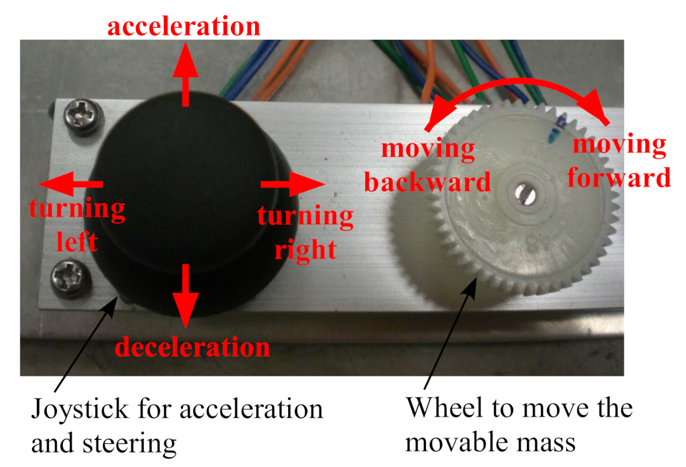
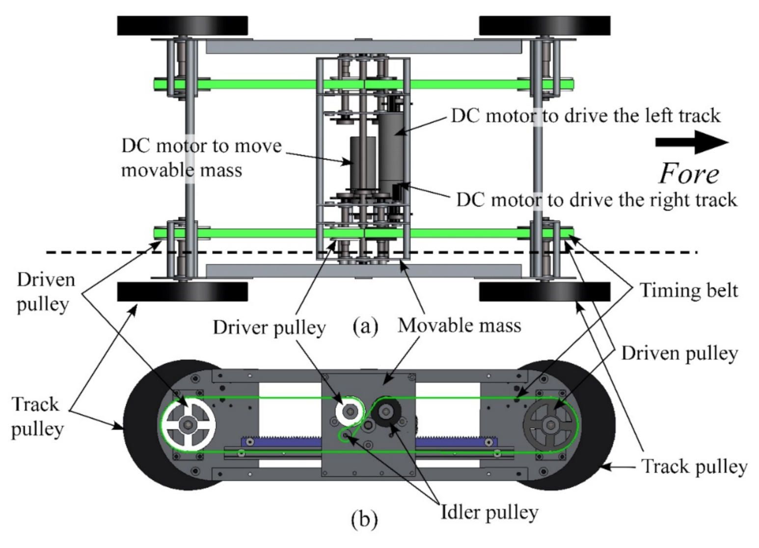
2.2. Mechanism to Drive the Movable Mass and Each Rubber Track

As shown in Figure 2, a pinion that protrudes on each side of the movable mass rolls over a rack, fixed on each side of the main body, allowing the movable mass to move forward and backward. The pinion is driven by a single motor equipped in the movable mass.
We propose a novel mechanism to transmit the driving force for each rubber track while its driving motor moves forward and backward in the movable mass. The CAD of Dyjob presented in Figure 4a,b shows, respectively, the top view and the right-hand side view at the dashed cross section in Figure 4a (the rubber tracks are omitted from the CAD). The driver pulley is turned by the DC motor for driving each track via the gear reduction mechanism, and the fore and rear driven pulleys are turned using the timing belt. Tension is applied by the two idler pulleys to prevent the belt from slipping off. The fore and rear final track pulleys are turned with the driven pulleys.
This proposed mechanism allows Dyjob to independently move the movable mass and the rubber tracks.

3. Analysis of Movement over a Step
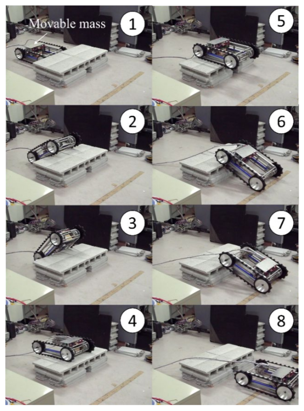
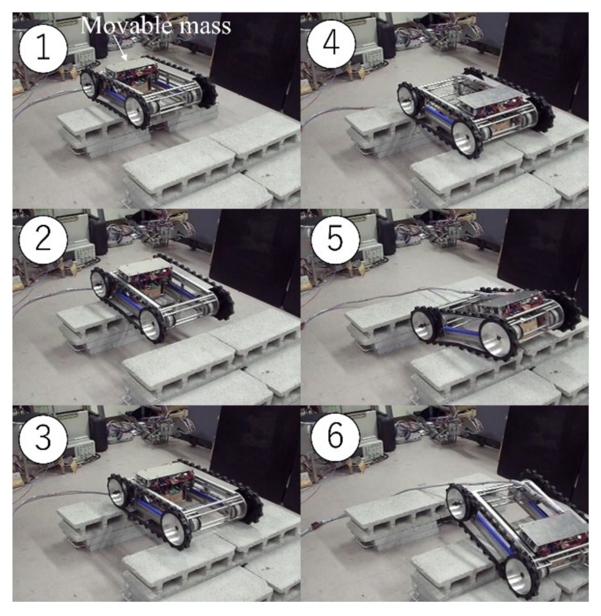
3.1. Strategy

The following three steps are necessary for a simple tracked vehicle to traverse a step:
Step (1)
The front end of the vehicle climbs onto the step.
Step (2)
The rear end of the vehicle climbs onto the step.
Step (3)
The vehicle lands on the ground without turning over forward.
We first analyze the condition for Step 1. For simplicity, Figure 5 shows a force diagram for the condition when the vehicle is stationary at the time the front end starts to move up along the step wall. A and B represent the contact points between the track and the ground and the step wall, respectively. N A and N B are normal forces applied to A and B; f A and f B are the static friction applied to A and B; and x and l are the distances between B and the COG and between A and B, respectively.
Since the horizontal and vertical forces are balanced in Figure 5, f A = N B and N A + f B = m g (where g is the acceleration of gravity). Considering moment equilibrium about B, N A l m g x = 0 holds, assuming that the vehicle is low enough. Therefore, we have the following:
N A = m g x l
and:
f B = m g 1 x l .    
The conditions for the vehicle not to slip at A and B are f A < μ A N A and f B < μ B N B , respectively, where μ A and μ B are the coefficients of static friction at A and B. Therefore, the larger value of x in Equations (1) and (2) allows the conditions to be easily met. This means the backward-positioned COG can prevent the track from slipping on the ground and wall, thus providing large propulsion needed to achieve Step 1.
Since μ A and μ B depend on the surfaces of the terrain and step wall, respectively, the conditions f A < μ A N A and f B < μ B N B are variable according to the environment. Some works estimate contact models between the vehicle and the ground for autonomous off-road UGVs [36,37,38]. For our teleoperated vehicle, the operator judges whether the vehicle is slipping through the onboard camera and manually controls the acceleration and the movable mass position to achieve Step 1.
We will analyze Step 2 in Section 3.2.
Regarding Step 3, the forward-positioned COG causes the front end to land on the ground at a steep angle, as shown in Figure 6a. In addition, since the COG is close to the contact point P, the vehicle easily turns over. The backward-positioned COG can avoid the risk of turning over, as shown in Figure 6b.

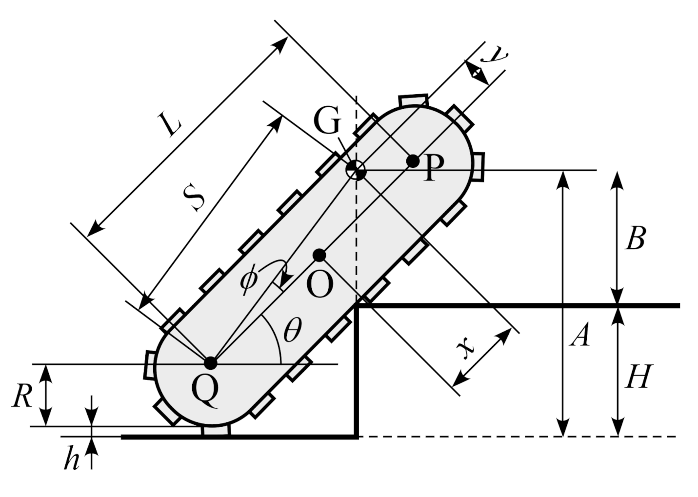
3.2. Geometric Analysis of Effect of Adjustment of COG Position on Rear End of the Vehicle Climbing a Step

Here, we analyze the geometric boundary condition needed to achieve Step 2 after finishing Step 1, as shown in Figure 7. Here, the Points O, P, and Q are the center of the vehicle and the centers of the front and rear track pulleys, respectively; R and h represent the radius of the track pulley and the height of the lug, respectively; and x and y represent, respectively, the forward and upward distances between O and COG. The time when the COG is located directly above the edge of the step, as shown in Figure 6, is the boundary condition required for the vehicle to achieve Step 2.
The height of a step that the vehicle can climb is given by:
H = A B ,  
where A and B are the heights of the COG from the ground and the step tread, respectively. From Figure 7, we see that:
A = R + h + S sin θ + ϕ ,  
where:
S = x + L / 2 2 + y 2 ,   ϕ = tan 1 y x + L / 2   ,
and:
B = R + y cos θ .    
Equation (3) is rewritten by substituting Equations (4) and (5) as:
H = R + h + x + L / 2 2 + y 2 sin θ + tan 1 2 y 2 x + L R + y cos θ .
Figure 8 shows the relation between the vehicle tilt ( θ ) and step height ( H ) based on Equation (6) for Dyjob ( R = 0.077   m ,   h = 0.013   m ,   L = 0.42   m ,   y = 0.006   m ) with several COG positions determined by the different values of x and y . The red dashed and solid lines show the cases in which the movable mass is fixed (i) in the center O ( x = 0 ) and (ii) in the forwardmost position, i.e., x = 0.0585   m (142 mm forward from O), respectively. In cases (i) and (ii), Dyjob is assumed to be able to climb steps of 0.126 m high when θ = 0.84 rad and 0.171 m high when θ = 0.89 rad, respectively. Therefore, Dyjob should place the movable mass as far forward as possible (i.e., x = 0.0585   m ) in Step 2.
The blue and green lines in Figure 8 show the results for cases with the same conditions as in (i) and (ii) but with a higher COG ( y = 0.05   m   and   0.1   m , respectively). Since the higher COG tends to cause the vehicle to easily flip over backward when it is tilted, as shown in Figure 1, the step heights that Dyjob can climb in Step 2 are limited in the cases with larger y , as shown in Figure 8. This means that the proposed COG-movable mechanism in the lower position enables the vehicle to traverse a high step even though the COG shifts a relatively short distance.

4. Experimental Results

We conducted experiments with Dyjob moving over a step, climbing stairs, moving over a gap, and moving up a steep slope. The shapes of these obstacles were laterally invariable, similar to the closely related works [30,31,32,33,34,35], to simply confirm the effectiveness of our proposed mechanism in this paper. Although Dyjob was powered by an external power supply, a suitable number of unused batteries were installed.

4.1. Experiments with “Dyjob” Moving over a Step

The analysis in Section 3 indicated that Dyjob should shift the movable mass to the furthest possible point backward in Step 1 and Step 3 and the furthest point forward in Step 2. We first conducted experiments with Dyjob moving over a step. Dyjob could successfully traverse a step of 180 mm high, which is the same height as Dyjob itself, and 400 mm deep. A movie of this experiment is presented in the Supplementary Video S1. Figure 9 shows some snapshots of the movie. The magenta and light green lines in Figure 10 show Dyjob’s tilt and the movable mass position in the experiment. The tilt θ , the same as in Figure 7, is positive when the vehicle tilts backward. The movable mass position is zero when it is placed at the center of Dyjob and positive when it moves forward. Each circled number in Figure 10 shows the time of the corresponding snapshot in Figure 9.
In Step 1, the tracks slipped on the ground and the step wall with the movable mass kept in the center, thus preventing Dyjob from lifting its front end onto the step. Moving the movable mass the furthest backward, as shown in No. 1 in Figure 9, allowed the front end of Dyjob to move up onto the step, as shown in No. 2. It is similarly observed in Figure 10 that because the movable mass was placed the furthest backward between No. 1 and 2, Dyjob was able to tilt up to approximately 0.6 rad.
For Step 2, the operator moved the movable mass the furthest forward while Dyjob was tilted up, as observed between No. 2 and 3 of Figure 10. Consequently, after Dyjob was tilted up by approximately 0.8 rad, the tilt steeply dropped to zero, as shown in No. 4 of Figure 10, and the vehicle landed on the step (see No. 4 in Figure 9). Without moving the movable mass the furthest forward, Dyjob was not able to achieve Step 2.
For Step 3, the operator moved the movable mass the furthest backward between No. 4 and 5 of Figure 9 and Figure 10 to safely land Dyjob on the ground. Subsequently, Dyjob moved forward, and the front end landed on the ground without the vehicle turning over, as shown in No. 6 of Figure 9. In the case that Dyjob proceeded while keeping the movable mass forward, as shown in No. 4 of Figure 9, Dyjob was vertically tilted down in No. 6 of Figure 9, thereby flipping over. If the rear end falls from the step while the movable mass was kept backward, as shown in No. 6 of Figure 9, the devices in the mass will be damaged. Therefore, the operator moved the mass forward, as shown in No. 7 of Figure 9, and Dyjob safely landed on the ground, as shown in No. 8 of Figure 9.
Dyjob with the adjusted COG position could traverse a step of up to 180 mm high, while without COG adjustment it could traverse a step of up to 120 mm high. The results are similar to our analytical results shown in Figure 8, although the Dyjob experiments were occasionally dynamic.

4.2. Experiments with “Dyjob” Climbing up Stairs

We conducted an experiment with Dyjob climbing four step stairs, as shown in Figure 11, in which each step is 180 mm high and 280 mm deep. The movie is provided in the Supplementary Video S2. The same methods as in Section 4.1 were used for Step 1 (Nos. 2–4 in Figure 11) and Step 2 (Nos. 5 and 6). After Step 2, Dyjob maintained the forward COG position until the end (No. 8). Without adjusting the COG position, Dyjob was not able to achieve even Step 1.

4.3. Experiments with “Dyjob” Moving over a Gap

Adjustment of the COG position is also useful when Dyjob is moving over a gap. Figure 12 shows snapshots of the experiments with Dyjob traversing a 0.32-m-long gap. A movie is provided in the Supplementary Video S3. Because Dyjob progressed while keeping the movable mass the furthest backward, as shown in No. 1 and 2 of Figure 12, the front end safely reached the opposite side without falling into the gap, as shown in No. 3. Subsequently, Dyjob kept the COG position the furthest forward by moving the movable mass the furthest forward, as shown in No. 4. This enabled Dyjob to keep the COG position above the opposite side just after the rear end left the block, as shown in No. 5, eventually traversing the gap, as shown in No. 6. When the movable mass was kept in the center, the front end fell into the gap in No. 2., and when the mass was not moved forward in No. 4, the rear end fell into the gap before reaching the state of No. 5.

4.4. Experiments with “Dyjob” Climbing a Slope

The proposed mechanism of moving a vehicle’s COG at a low level contributes to reducing the risk of turning over on irregularly inclined terrains. While Dyjob was passing over the step (Section 4.1) and stairs (Section 4.2) slightly diagonally in the horizontal plane, there was a small possibility of slipping down but little chance of overturning.
In the case that a vehicle has its COG at a high position (G2 in Figure 13), similar to vehicles that can move their COG [30,31,32,33,34,35], the vehicle turns over around P in Figure 13 at relatively gentle angles of θ . However, it is expected that Dyjob, which has its COG at the low and most forward position G1 ( x = 0.0585   m ,   y = 0.006   m ), is stable at steep angles given by:
θ < 0.99   rad .
It is expected that Dyjob does not slip down a slope on which the coefficient of kinetic friction μ is 1.12 if
θ < tan 1 μ = tan 1 1.12 = 0.842   rad .
Equations (7) and (8) establish a condition ( θ < 0.842   rad ) for the vehicle to be able to steadily continue to climb the slope.
In experiments, Dyjob successfully achieved climbing slopes ( μ = 1.12 ) with θ < 0.80 rad. The movie and snapshot of Dyjob climbing a slope of 0.80 rad are provided in the Supplementary Video S4 and Figure 14. This result demonstrates that our proposed mechanism of moving a vehicle’s COG at a low level is effective in moving on inclined terrains.

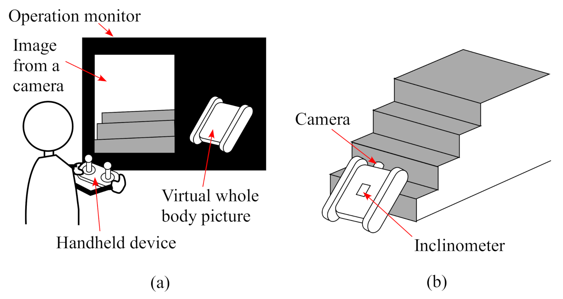
5. Discussion on Operation

Operation methods of a UGV are generally categorized into three classes [39], which are autonomous control [40], semi-autonomous control [41], and teleoperation [28]. For Dyjob, a human teleoperates not only the movement of the tracks for progression and steering, but also the movable mass. This is because the strategy to control the movable mass is not as simple as just keeping the COG in a capture region [42] to ensure its stability. For example, to achieve Step 1 of Section 3.1 for climbing a step (Section 4.1) and stairs (Section 4.2), the vehicle has to lift the front end by moving the movable mass backward while progressing. To achieve Step 2, the vehicle has to move the moveable mass forward to allow the front body to fall forward onto the step. To move over a gap (Section 4.3), the vehicle simply shifts the movable mass to ensure its stability. However, before doing this, the vehicle has to precisely recognize the hole position. Irregular and complicated decision making is needed depending on the type of terrain, causing difficulty in autonomous control. Therefore, we conclude that manual operation is more practical at the current stage. Our proposed mechanical design of shifting the mass at a low level allows the risk of overturning caused by operation mistakes to decrease. In addition, our vehicle can progress even in the worst-case scenario of the UGV turning upside down caused by the operator‘s mistakes. We aim to build a simple, reasonable and durable UGV.
Figure 15 shows a specific prospective image of teleoperation of Dyjob. Dyjob’s stability and controllability depend on maneuverability by a remote operator through the handheld device. Therefore, intuitive real-time information should be provided for the operator from a variety of sensors. Dyjob will be equipped with a front camera to recognize the environment, but it is difficult for the operator to recognize the posture from the transmitting images from the camera. The posture recognition is important to achieve Steps 1–3 in Section 3.1. We plan to display a tilted virtual whole-body picture on a monitor that the operator watches, such as is used for a “Quince” robot [28]. The picture will be reproduced based on body tilt information around the pitch and roll axes obtained from inclinometers on the vehicle.

6. Conclusions

Unmanned ground vehicles (UGVs) that aim to travel over obstacles are typically classified into legged, legged-wheeled, wheeled, and tanked forms. It is known that the former types can move over higher obstacles, but have more degrees of freedom. Legged vehicles can significantly shift their centers of gravity (COG) by positioning their multi-articulated legs at appropriate trajectories while stepping over a high obstacle. To realize a COG movable mechanism with a small number of joints on conventional wheeled and tracked vehicles, some vehicles have been developed that can travel over a high step by explicitly shifting a heavy mass with a single or two degrees of freedom to change their COG position. However, these UGVs tend to shift the mass at a high position, causing instability.
To address this issue, we proposed a mechanism for simple tracked vehicles in which the COG can be moved forward and backward at a lower level. Based on this mechanism, we developed a prototype called “Dyjob”, in which the movable mass contained all the heavy geared motors as well as electric devices and batteries. Experimental results confirmed that Dyjob with the significant movement of COG could successfully traverse a step, stairs, and a gap.
Since Dyjob is still a prototype, further improvements are being considered. For example, lightening the parts except for the movable mass will increase the weight ratio of the movable mass to the whole body. In addition, increasing the moving distance of the movable mass will enhance the performance. This proposed mechanism is also available for conventional four-wheel vehicles.

Supplementary Materials

The following are available online at https://www.mdpi.com/article/10.3390/app12010525/s1, Video S1: Dyjob moving over a step. Video S2: Dyjob climbing up stairs. Video S3: Dyjob moving over a gap. Video S4: Dyjob climbing a slope.

Author Contributions

Conceptualization, Y.F.; methodology, Y.F.; software, K.O.; validation, Y.F. and K.O.; formal analysis, Y.F. and K.O.; investigation, Y.F. and K.O.; resources, Y.F. and K.O.; data curation, Y.F. and K.O.; writing—original draft preparation, Y.F., K.O., and A.N.I.; writing—review and editing, Y.F. and A.N.I.; visualization, Y.F. and K.O.; supervision, Y.F.; project administration, Y.F.; funding acquisition, Y.F. All authors have read and agreed to the published version of the manuscript.

Funding

This research received no external funding.

Institutional Review Board Statement

Not applicable.

Informed Consent Statement

Not applicable.

Data Availability Statement

The data presented in this study are available on request from the corresponding author.

Conflicts of Interest

The authors declare no conflict of interest.

References

  1. Boston Dynamics. Available online: https://www.bostondynamics.com/ (accessed on 29 December 2021).
  2. Kim, S.; Clark, J.E.; Cutkosky, M.R. iSprawl: Design and Tuning for High-speed Autonomous Open-loop Running. Int. J. Robot. Res. 2006, 25, 903–912. [Google Scholar] [CrossRef]
  3. Murphy, M.P.; Saunders, A.; Moreira, C.; Rizzi, A.A.; Raibert, M. The LittleDog robot. Int. J. Robot. Res. 2011, 30, 145–149. [Google Scholar] [CrossRef]
  4. Semini, C.; Barasuol, V.; Boaventura, T.; Frigerio, M.; Focchi, M.; Caldwell, D.G.; Buchli, J. Towards versatile legged robots through active impedance control. Int. J. Robot. Res. 2015, 34, 1003–1020. [Google Scholar] [CrossRef]
  5. Bjelonic, M.; Kottege, N.; Beckerle, P. Proprioceptive control of an over-actuated hexapod robot in unstructured terrain. In Proceedings of the IEEE/RSJ International Conference on Intelligent Robots and Systems (IROS 2016), Daejeon, Korea, 9–14 October 2016. [Google Scholar]
  6. Fukui, T.; Fujisawa, H.; Otaka, K.; Fukuoka, Y. Autonomous gait transition and galloping over unperceived obstacles of a quadruped robot with CPG modulated by vestibular feedback. Robot. Auton. Syst. 2019, 111, 1–19. [Google Scholar] [CrossRef]
  7. Xin, G.-Y.; Wolfslag, W.; Lin, H.-C.; Tiseo, C.; Mistry, M. An Optimization-Based Locomotion Controller for Quadruped Robots Leveraging Cartesian Impedance Control. Front. Robot. AI 2020, 7, 48. [Google Scholar] [CrossRef] [Green Version]
  8. Daltorio, K.A.; Wei, T.E.; Horchler, A.D.; Southard, L.; Wile, G.D.; Quinn, R.D.; Gorb, S.N.; Ritzmann, R.E. Mini-Whegs TM Climbs Steep Surfaces Using Insect-inspired Attachment Mechanisms. Int. J. Robot. Res. 2009, 28, 285–302. [Google Scholar] [CrossRef]
  9. Zhang, C.; Zou, W.; Ma, L.; Wang, Z. Biologically inspired jumping robots: A comprehensive review. Robot. Auton. Syst. 2020, 124, 103362. [Google Scholar] [CrossRef]
  10. Collins, S.; Ruina, A.; Tedrake, R.; Wisse, M. Efficient Bipedal Robots Based on Passive-Dynamic Walkers. Science 2005, 307, 1082–1085. [Google Scholar] [CrossRef] [PubMed] [Green Version]
  11. Saranli, U.; Buehler, M.; Koditschek, D.E. RHex: A Simple and Highly Mobile Hexapod Robot. Int. J. Robot. Res. 2001, 20, 616–631. [Google Scholar] [CrossRef] [Green Version]
  12. Kim, Y.-S.; Jung, G.-P.; Kim, H.; Cho, K.-J.; Chu, C.-N. Wheel Transformer: A Wheel-Leg Hybrid Robot with Passive Transformable Wheels. IEEE Trans. Robot. 2014, 30, 1487–1498. [Google Scholar] [CrossRef]
  13. Laumond, J.; Benallegue, M.; Carpentier, J.; Berthoz, A. The Yoyo-Man. Int. J. Robot. Res. 2017, 36, 1508–1520. [Google Scholar] [CrossRef] [Green Version]
  14. Eich, M.; Grimminger, F.; Kirchner, F. Proprioceptive control of a hybrid legged-wheeled robot. In Proceedings of the 2008 IEEE International Conference on Robotics and Biomimetics, Bangkok, Thailand, 22–25 February 2009. [Google Scholar]
  15. Breckwoldt, W.; Bachmann, R.; Leibach, R.; Quinn, R. Speedy whegs climbs obstacles slowly and runs at 44 km/hour. In Proceedings of the Conference on Biomimetic and Biohybrid Systems, Living Machines 2019: Biomimetic and Biohybrid Systems, Nara, Japan, 9–12 July 2019; pp. 27–37. [Google Scholar]
  16. Dalvand, M.M.; Moghadam, M.M. Stair Climber Smart Mobile Robot (MSRox). Auton. Robot. 2006, 20, 3–14. [Google Scholar] [CrossRef]
  17. Quaglia, G.; Nisi, M. Design and construction of a new version of the Epi.q UGV for monitoring and surveillance tasks. In Proceedings of the ASME 2015 International Mechanical Engineering Congress and Exposition, Houston, TX, USA, 13–19 November 2015. [Google Scholar]
  18. Endo, G.; Hirose, S. Study on Roller-Walker—Improvement of Locomotive Efficiency of Quadruped Robots by Passive Wheels. Adv. Robot. 2012, 26, 969–988. [Google Scholar] [CrossRef] [Green Version]
  19. Du, W.; Fnadi, M.; Benamar, F. Rolling based locomotion on rough terrain for a wheeled quadruped using centroidal dynamics. Mech. Mach. Theory 2020, 153, 103984. [Google Scholar] [CrossRef]
  20. Du, W.; Amar, F. A compact form dynamics controller for a high-DOF tetrapod-on-wheel robot with one manipulator via null space based convex optimization and compatible impedance controllers. Multibody Syst. Dyn. 2020, 49, 447–463. [Google Scholar] [CrossRef]
  21. Estier, T.; Piguet, R.; Eichhorn, R.; Siegwart, R. Shrimp, a rover architecture for long range martian mission. In Proceedings of the Sixth ESA Workshop on Advanced Space Technologies for Robotics and Automation (ASTRA’2000), Noordwijk, The Netherlands, 5–7 December 2000. [Google Scholar]
  22. Cordes, F.; Kirchner, F.; Babu, A. Design and field testing of a rover with an actively articulated suspension system in a Mars analog terrain. J. Field Robot. 2018, 35, 1149–1181. [Google Scholar] [CrossRef]
  23. Harrington, B.D.; Voorhees, C. The challenges of designing the rocker-bogie suspension for the Mars Exploration Rover. In Proceedings of the of the 37th Aerospace Mechanisms Symposium, Galveston, TX, USA, 19–21 May 2004. [Google Scholar]
  24. Nayar, H.; Kim, J.; Chamberlain-Simon, B.; Carpenter, K.; Hans, M.; Boettcher, A.; Meirion-Griffith, G.; Wilcox, B.; Bittner, B. Design optimization of a lightweight rocker–bogie rover for ocean worlds applications. Int. J. Adv. Robot. Syst. 2019, 16, 1–10. [Google Scholar] [CrossRef]
  25. Takamori, T.; Kobayashi, S.; Ohira, T.; Takashima, M.; Ikeuchi, A.; Takashima, S. Development of UMRS (Utility Mobile Robot for Search) and searching system for sufferers with cellphone. In Proceedings of the First International Symposium on System & Human Science—For Safety, Security, and Dependability, Osaka, Japan, 19–20 November 2003; pp. 47–52. [Google Scholar]
  26. Yamauchi, B.M. PackBot: A versatile platform for military robotics. In Proceedings of the SPIE 5422, Unmanned Ground Vehicle Technology VI, Orlando, FL, USA, 13–15 April 2004. [Google Scholar]
  27. Kamimura, A.; Kurokawa, H. High-step climbing by a crawler robot DIR-2—Realization of automatic climbing motion. In Proceedings of the 2009 IEEE/RSJ International Conference on Intelligent Robots and Systems, St. Louis, MO, USA, 11–15 October 2009. [Google Scholar]
  28. Nagatani, K.; Kiribayashi, S.; Okada, Y.; Otake, K.; Yoshida, K.; Tadokoro, S.; Nishimura, T.; Yoshida, T.; Koyanagi, E.; Fukushima, M.; et al. Emergency response to the nuclear accident at the Fukushima Daiichi Nuclear Power Plants using mobile rescue robots. J. Field Robot. 2013, 30, 44–63. [Google Scholar] [CrossRef]
  29. Nakamura, K.; Tohashi, K.; Funayama, Y.; Harasawa, H.; Ogawa, J. Dual-arm robot teleoperation support with the virtual world. Artif. Life Robot. 2020, 25, 286–293. [Google Scholar] [CrossRef]
  30. Sim, B.-S.; Kim, K.-J.; Yu, K.-H. Development of body rotational wheeled robot and its verification of effectiveness. In Proceedings of the 2020 IEEE International Conference on Robotics and Automation (ICRA), Paris, France, 31 May–31 August 2020; pp. 10405–10411. [Google Scholar]
  31. Falcone, E.; Gockley, R.; Porter, E.; Nourbakhsh, I. The Personal Rover Project: The comprehensive design of a domestic personal robot. Robot. Auton. Syst. 2003, 42, 245–258. [Google Scholar] [CrossRef]
  32. Nishio, N.; Nishida, S.-I.; Nakatani, S. Study of a Planetary Exploration Rover with a Hinge-type Center-of-gravity Shift Mechanism. Trans. Jpn. Soc. Aeronaut. Space Sci. Aerosp. Technol. Jpn. 2021, 19, 469–476. [Google Scholar] [CrossRef]
  33. Nakamura, S.; Faragalli, M.; Mizukami, N.; Nakatani, I.; Kunii, Y.; Kubota, T. Wheeled robot with movable center of mass for traversing over rough terrain. In Proceedings of the 2007 IEEE/RSJ International Conference on Intelligent Robots and Systems (IROS), San Diego, CA, USA, 29 October–2 November 2007; pp. 1228–1233. [Google Scholar]
  34. Yokoyama, M.; Matsuhasi, Y.; Sano, A.; Ko, M.T. Slip control of a wheeled mobile robot with a movable auxiliary mass. In Proceedings of the 2015 IEEE International Conference on Advanced Intelligent Mechatronics (AIM), Busan, Korea, 7–11 July 2015; pp. 1008–1013. [Google Scholar]
  35. Onozuka, Y.; Tomokuni, N.; Murata, G.; Shino, M. Dynamic stability control of inverted-pendulum-type robotic wheelchair for going up and down stairs. In Proceedings of the 2020 IEEE/RSJ International Conference on Intelligent Robots and Systems (IROS), Las Vegas, NV, USA, 25–29 October 2020; pp. 4114–4119. [Google Scholar]
  36. Iagnemma, K.D.; Dubowsky, S. Terrain estimation for high-speed rough-terrain autonomous vehicle navigation. In Proceedings of the SPIE 4715, Unmanned Ground Vehicle Technology IV, Orland, FL, USA, 1–5 April 2002. [Google Scholar]
  37. Fnadi, M.; Plumet, F.; Benamar, F. Nonlinear tire cornering stiffness observer for a double steering off-road mobile robot. In Proceedings of the 2019 IEEE International Conference on Robotics and Automation (ICRA), Montreal, QC, Canada, 20–24 May 2019. [Google Scholar]
  38. Fnadi, M.; Du, W.; Plumet, F.; Benamar, F. Constrained Model Predictive Control for dynamic path tracking of a bi-steerable rover on slippery grounds. Control Eng. Pract. 2020, 107, 104693. [Google Scholar] [CrossRef]
  39. Delmerico, J.; Mintchev, S.; Giusti, A.; Gromov, B.; Melo, K.; Horvat, T.; Cadena, C.; Hutter, M.; Ijspeert, A.; Floreano, D.; et al. The current state and future outlook of rescue robotics. J. Field Robot. 2019, 36, 1171–1191. [Google Scholar] [CrossRef]
  40. Hebert, M.H.; Thorpe, C.; Stentz, A. Intelligent Unmanned Ground Vehicles. In The Springer International Series in Engineering and Computer Science; Springer: New York, NY, USA, 1997. [Google Scholar]
  41. Casper, J.; Murphy, R.R. Human-robot interactions during the robot-assisted urban search and rescue response at the World Trade Center. IEEE Trans. Syst. Man, Cybern. Part B (Cybern.) 2003, 33, 367–385. [Google Scholar] [CrossRef] [PubMed] [Green Version]
  42. Pratt, J.; Carff, J.; Drakunov, S.; Goswami, A. Capture point: A step toward humanoid push recovery. In Proceedings of the 2006 IEEE/RAS International Conference on Humanoid Robots, Genova, Italy, 4–6 December 2006. [Google Scholar]
Figure 1. An unmanned ground vehicle with high (A–A’) and low (B–B’) positions of center of gravity moving on a step.
Applsci 12 00525 g001
Figure 2. A prototype tracked vehicle “Dyjob”.
Applsci 12 00525 g002
Figure 3. A handheld device to operate “Dyjob”.
Applsci 12 00525 g003
Figure 4. CADs of “Dyjob”: (a) the top view and (b) the right-hand side view at the dashed cross section in (a). The rubber tracks are omitted.
Applsci 12 00525 g004
Figure 5. Force diagram when the vehicle stops at the time the front end starts to move up along the step wall.
Applsci 12 00525 g005
Figure 6. High (a) and low (b) risks of turning over with the adjustable COG position when the vehicle is landing on the ground.
Applsci 12 00525 g006
Figure 7. Diagram of the vehicle climbing a step.
Applsci 12 00525 g007
Figure 8. Assumed step heights that “Dyjob” can climb with the tilt in Step 2, as calculated with Equation (6) by a geometric analysis.
Applsci 12 00525 g008
Figure 9. Snapshots of “Dyjob” traversing a step.
Applsci 12 00525 g009
Figure 10. Experimental results for Dyjob traversing a step. Each circled number shows the moment of the corresponding snapshot in Figure 9.
Applsci 12 00525 g010
Figure 11. Snapshots of “Dyjob” climbing up stairs.
Applsci 12 00525 g011
Figure 12. Snapshots of “Dyjob” traversing a gap.
Applsci 12 00525 g012
Figure 13. Diagram of a vehicle climbing a slope.
Applsci 12 00525 g013
Figure 14. Snapshot of “Dyjob” climbing a 0.80 rad-inclined slope.
Applsci 12 00525 g014
Figure 15. Prospective image of teleoperation of “Dyjob”. (a) teleoperation and (b) remote field.
Applsci 12 00525 g015
Table 1. Dyjob’s specification.
Physical Feature and DeviceSpecification
Length600 mm
Width360 mm
Height180 mm excluding the protruding part of the movable mass
Whole weight8.5 kg
Weight of the movable mass3.5 kg
Coefficient of friction between the rubber track and an indoor hard ground0.82
Coefficient of friction between the rubber track and a block as an obstacle1.13
Coefficient of friction between the rubber track and a slope1.12
Moving range of the movable mass ± 0.142 m from the center of Dyjob
Moment of inertia about the axis O in Figure 2 when the movable mass is placed in the center0.275 kgm2
Moment of inertia about the axis O in Figure 2 when the movable mass is placed most forward/backward0.345 kgm2
Actuator for each track60 W DC motor (RE30 by Maxon) with reduction ratios of 36:1
Actuator for the movable mass60 W DC motor (RE30 by Maxon) with reduction ratios of 25:1
Motor driver1Axis DC Power Module by Hibot Co.
Encoder to detect the rotation angle of the track pulley and the movable mass’s positionMR Type L by Maxon
Inclinometer to detect the body tiltSCA61T-FA1H1G by VTI Technologies Co.
On-board computerHRP-3P-CN and MCN by General Robotics Inc.
Publisher’s Note: MDPI stays neutral with regard to jurisdictional claims in published maps and institutional affiliations.

