Article

Mobile Robots and Cobots Integration: A Preliminary Design of a Mechatronic Interface by Using MBSE Approach

by
Ferdinando Vitolo
1,
Andrea Rega
2,
Castrese Di Marino
3,
Agnese Pasquariello
1,*,
Alessandro Zanella
4 and
Stanislao Patalano
1
1
Fraunhofer J-Lab IDEAS, Department of Industrial Engineering, University of Naples Federico II, 80125 Naples, Italy
2
Department of Neurosciences, Reproductive and Odontostomatological Sciences, University of Naples Federico II, 80131 Naples, Italy
3
Department of Management, Information and Production Engineering, University of Bergamo, 24129 Bergamo, Italy
4
Centro Ricerche FIAT SCpA, 10043 Orbassano, Italy
*
Author to whom correspondence should be addressed.
Appl. Sci. 2022, 12(1), 419; https://doi.org/10.3390/app12010419
Submission received: 10 November 2021 / Revised: 23 December 2021 / Accepted: 29 December 2021 / Published: 2 January 2022
(This article belongs to the Special Issue Focus on Integrated Collaborative Systems for Smart Factory)

Abstract

:
Enabling technologies that drive Industry 4.0 and smart factories are pushing in new equipment and system development also to prevent human workers from repetitive and non-ergonomic tasks inside manufacturing plants. One of these tasks is the order-picking which consists in collecting parts from the warehouse and distributing them among the workstations and vice-versa. That task can be completely performed by a Mobile Manipulator that is composed by an industrial manipulator assembled on a Mobile Robot. Although the Mobile Manipulators implementation brings advantages to industrial applications, they are still not widely used due to the lack of dedicated standards on control and safety. Furthermore, there are few integrated solutions and no specific or reference point allowing the safe integration of mobile robots and cobots (already owned by company). This work faces the integration of a generic mobile robot and collaborative robot selected from an identified set of both systems. The paper presents a safe and flexible mechatronic interface developed by using MBSE principles, multi-domain modeling, and adopting preliminary assumptions on the hardware and software synchronization level of both involved systems. The interface enables the re-using of owned robot systems differently from their native tasks. Furthermore, it provides an additional and redundant safety level by enabling power and force limiting both during cobot positioning and control system faulting.

1. Introduction

History teaches us that production efficiency and working conditions were the main agents that have pushed the industrial-technological progress to overcome the manufacturing limits of different ages [1]. Nowadays, a new technological progress is currently happening with the advent of Industry 4.0 in which one of the main goals is the Human-Robot Collaboration (HRC) [2]. Collaborative robots (cobots) are entering the market and they will work safely side-by-side with humans without any physical fences as safety separation. The main purpose of HRC is indeed combining the high levels of accuracy, speed, and repeatability of robots with the flexibility and cognitive skills of human workers [3]. Moreover, human workers could be free themselves of non-ergonomic and repetitive tasks [4]. One of these manufacturing repetitive tasks is the carrying components from the warehouse to the working stations and vice-versa. Mobile robots, as Automated Guided Vehicles (AGVs) and their evolution in Autonomous Mobile Robots (AMRs), are designed to avoid human workers to perform carrying tasks allowing them to focus on knowledge-based and high value-added jobs [5]. In particular, AMRs have got several features not only for moving products or stuff inside the factory, but also for interacting with other machines and human workers by re-planning their trajectory as required [6]. Several research laboratories and companies have devoted time to integrating manipulators/cobots and mobile robots generating a new system named mobile manipulator/cobot. Due to this new industrial equipment, repetitive tasks, as the pick and place, have been transferred from human to robot, leading the first to focus on other tasks such as inspection of parts [7].
Currently, the market offers few integrated solutions for mobile manipulators but no specific indications or devices are allowing the safe integration of mobile robots and cobots, already owned by the company. The slow spreading of mobile manipulators in the industry is mainly due to the lack of reference safety standards. It follows that much more implementations are instead present in research laboratories where experts are currently figuring out how to deal with the decision-making process involving both systems. One of the main challenges is to establish coordinated movements between the base and the arm in an unstructured environment depending on the application [8]. The control logic is important not only for programming operational tasks but also for training the mobile robot and the manipulator to face the unexpected hazards of the operating environment.
In such a context, it is obvious the advantage that could be obtained by combining together generic collaborative and mobile robots. The system’s connection can be performed using an interface system allowing: (i) hardware connection by using a mechanical coupling of mobile robot and manipulator; (ii) software connection for the concurrent control of both systems as an additional safety measure.
The present paper deals with the preliminary design of a mechatronic interface by using RFLP (Requirements-Functional-Logical-Physical) and Model-Based System Engineering (MBSE) approaches. Those methodologies enable us to start from identified needs and to transform them into a first interface concept with the aid of modeling and simulation. Flexibility and safety are the main requirements that also represent the research activity objective. The flexibility is assumed as the ability to overcome the limitations of the built-in market solutions. Safety is assumed as the capability to safely integrate systems for which dedicated safety standards are non yet implemented. The interface allows one to join a generic mobile robot to a generic collaborative robot selected from an identified set of both systems. The interface will allow the rotation and the positioning of the cobot with respect to the mobile robot. This motion will be controlled to avoid harmful collisions with human operators. Indeed, the motion of the entire cobot around the vertical axis is the most hazardous because the maximum inertia is involved.
The paper is organized as follows. Section 2 briefly presents a state of art about the two main systems to be integrated (collaborative robots and mobile robots) and the main problems connected to the integration. Section 3 provides the basics of MBSE and the RFLP approach for mechatronic system design. Section 4, Section 5 and Section 6 present the application of the previously cited approach to the preliminary design of the mechatronic interface. In Section 7, an evaluation of the obtained results is discussed and a critical review is given in Section 8.

2. State of Art

This section presents a critical analysis of the state of art about mobile manipulators. The analysis was driven by one of the two main goals of the present paper: to develop an interface that can easily combine different types of cobots and mobile robots. The exploration of the principal available cobots and mobile robots led to the identification of a representative group for both of them. The definition of a mobile robot and the differences among AGVs, AMRs, and Autonomous Mobile Manipulators (AMMs) are presented. Furthermore, the term “Autonomous Mobile Cobot” (AMC) is introduced to meet the need of a scenario constantly evolving. Afterward, a background on the specific technology involving mobile manipulators will be presented. Finally, it focuses on safety and control issues.

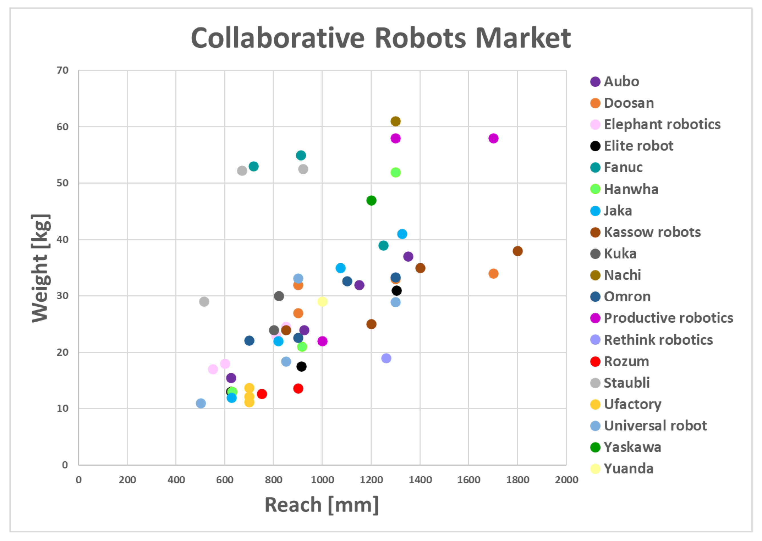
2.1. Collaborative Robots

Collaborative robots are robots able to work side by side with human operators [9]. According to the ISO 10218-2 [10] a cobot is a “robot designed for direct interaction with a human within a defined collaborative workspace”. Cobot applications have proved that is important to define the boundary of the collaborative workspace [11] which is the appointed space for Human-Robot Interaction (HRI).
About safety, industrial robots and cobots are quite different. Cobots use several and concurrent solutions to ensure a safe interaction with operators and the surroundings. They are built with lightweight materials and designed with rounded shapes. The cobots are equipped with a set of sensors to detect the surrounding space and the human presence. Finally, to reduce the potential damage to humans, they have torque and force sensors to detect unwanted contacts. Therefore, the collaborative robots are largely used where the collaboration with humans can increase the performance of the production or overcome the technical limitations without physical fences [12].
To classify the available commercial cobots and to identify the differences among them, three cobot market maps was developed by sampling a representative group of cobots based on the following criteria of interest for the systems integration: (i) the payload, (ii) the reach, (iii) the footprint and (iv) the weight. The weight and the footprint are selected as the main binding criteria. Indeed, the cobot should be mounted on a mobile robot that must be strong and large enough to support it. The footprint defines the minimum dimension that the mobile robot, and consequently the interface, should have. In the second stage, the payload and the reach have to be considered to evaluate the possible working conditions where the cobot should be adopted. The maximum payload combined with the weight of the cobot provides the minimum necessary capacity of both the mobile robot and interface. Moreover, the maximum reach of the cobot involves two important aspects: (i) safety and (ii) feasibility. Indeed, the reach determines which part of the human body can be achieved by the cobot and the effect on the stability of the mobile manipulator.
All the examined cobots are organized by three maps where the weight is compared respectively versus the payload (Figure 1), the reach (Figure 2) and the footprint (Figure 3). Each selected brand is represented using a defined color according to the figures’ legend.
The results highlight that cobots are characterized by: (i) a weight between 11 and 61 kg; (ii) a diameter of footprint between 120 and 310 mm; (iii) a reach between 500 and 1800 mm; (iv) a payload between 2 and 18 kg. The worst case, characterized by the sum of the weight and the maximum payload, is 71 kg. Furthermore, the robot with the maximum footprint has a diameter of 310 mm, a reasonable value that falls into the range of most mobile robots. Indeed, that is an important limitation for the dimension of the mobile robot and the interface, and it needs to be considered. Figure 1, Figure 2 and Figure 3 show that 80% of cobots have a weight lower than 40 kg, and only 25% of cobots have a footprint higher than 230 mm. Therefore, a representative group of the most common cobots can be characterized by the following features:
1.
weight up to 40 kg,
2.
payload between 2 and 18 kg,
3.
reach from 500 to 1800 mm and
4.
footprint up to 230 mm.

2.2. Mobile Robots

In manufacturing plants, mobile robots are widely adopted for logistic purposes. However, there is still confusion over the “mobile robot” term definition. It is mainly due to the existence of different kinds of mobile robots.
The most common type of such mobile robot is the AGV, introduced in 1953 by Barret Electronics, an American company from Northbrook, Illinois [13]. An AGV is a simple and slow transporting system constrained to follow a wire on the floor instead of a rail. The following evolution of the technology, in particular the microprocessors, allowed to equip the AGVs with on-board computers able to store the programmed paths and initiate motion using directional systems to make the vehicle follow the desired path. Nevertheless, modern solutions of AGVs are laser-based capable of determining their position and direction from the reflection of the laser on specific reflective tapes on walls, poles, or fixed machines [14]. Laser emission allows detecting fixed or mobile obstacles to define different paths to reach the destination. In modern context, many factories usually adopt AGVs in the warehouses to carry materials over great distances autonomously providing efficient and flexible performances.
On another hand, more recently, the AMRs [15] have been integrated into industrial applications. The main innovation compared to the AGVs is the capability to navigate autonomously from place to place and to execute specific tasks [6]. An AMR navigates using maps that can be loaded directly onto the robot, or that it builds autonomously on-site. If forklifts, pallets, people, or other obstacles are in its path, the AMR goes around safely, using the best alternative route.
Similarly, as cobots, a mobile robots market map has been developed (see Figure 4) by sampling a representative group of mobile robots based on the following criteria of interest for the systems integration:
1.
payload: the mobile robot has to bear the load of the cobots and the workpiece;
2.
battery life: for the autonomy of the mobile robot.
3.
height: for the reachability of the human body part;
The payload is the most important feature because the mobile robot has to carry not only the cobot but also the workpiece. Battery life could be a critical issue for the autonomy of the system and its operating performance. Height is the key feature for safety. Indeed, the human body parts reachable by the system are defined by the total height of the system obtained by combining the mobile robot and cobot heights [16]. The result of the market analysis is presented in Figure 4. The color of the circle represents the brand while the diameter size represents the battery charge. Figure 4 shows four classes of mobile robots according to the payload: up to 300 kg, 500–600 kg, 1000 kg, and 1500 kg. Furthermore, the mobile robots within 300 and 400 mm height are characterized by the higher battery charge (bigger diameters). In conclusion, the 81% of the examined mobile robots can be characterized by the following features:
1.
Height up to 400 mm,
2.
Payload between 90 and 1000 kg,
3.
Battery charge between 8 and 15 h.

2.3. Mobile Manipulators

Autonomous Mobile Manipulators (AMMs) are composed of the integration of a robotic arm and a mobile robot. The main goal of AMMs is to autonomously move around the manufacturing plant while letting the manipulator execute specific tasks. Some companies have proposed to add mobility to manipulators to extend their functionality and usefulness. Concurrently, several researchers have focused on the same objective. For instance, Helmes et al. [17] developed a mobile manipulator as a robot assistant to support the human worker. Bostelman et al. [15] presented the possibility to adopt AGVs or AMRs equipped with an anthropomorphic manipulator. On another hand, Hvilshøj et al. [7] provided a review about Autonomous Industrial Mobile Manipulators (AIMMs), identifying 12 possible application areas: sustainability, configuration, adaptation, autonomy, positioning, manipulation and grasping, robot-robot interaction, human-robot interaction, process quality, dependability, and physical properties. They found out that the biggest obstacles in this field are: dependability (safety), physical properties (economy), and configuration (usability). Bostelman et al. [18] present a review of the main AMMs and a set of evaluation criteria to assess their performances while Unger et al. [19] present a critical investigation of generic use cases where the AMMs can be applied. D’Souza et al. [20] present a hardware and software integration of cobot and AGV without taking into account safety aspects.

Safety and Control of Mobile Manipulators

In this context, the main challenge is the integration of cobots and mobile robots, already owned by a generic company, by controlling both the entities without considering them as two separate parts. The challenge refers not only to the scheduling of task processes but especially to the decision-making process which is responsible for both cobot and mobile robot reaction when an unexpected event occurs. Moreover, even though standards provide detailed safety requirements for both industrial manipulators and mobile robots, there is a lack of safety regulation for mobile manipulators. The ISO 10218-1 [21] and ISO 10218-2 [10] provide prescriptions on how to deal with hazards presented by industrial robots and industrial robot systems and their integration into workplaces, whereas the ISO/TS 15066 [16] specializes in collaborative operations. On the other hand, the ISO 3691-4 [22] specifies safety requirements for driver-less industrial trucks and their systems (i.e., AGVs and AMRs). Mobile manipulators are currently not regulated by standards nor guidelines which can assess the new risks related to the integration of the two systems.
In this context, many authors have dealt with the identification and analysis of the possible scenarios with the AMM, by providing recommendations and guidelines. Markis et al. [23] identified two possible configurations for a mobile manipulator starting from the possible states of the robotic arm. If the robotic arm always rests during the mobile robot motion, it might be considered as a load and the risk assessment for the total hazard is led by mobile robots standards. Otherwise, when the robotic arm is moving, all three aforementioned standards come to the rescue. Therefore, these scenarios report common situations already considered by the manufacturers of cobots and mobile robots. However, the combination of them presents relevant changes of their working context that needs an additional safety measure provided by a third system that put in communication them.
Indeed, it is not clearly nor readily identifiable which safety standard takes precedence when both systems are moving. For this reason, it might be mandatory to take into account special hazardous situations that can occur in industrial robotic applications with mobile manipulators from the beginning [24]. In this way, engineers can not trust only the inherently safe design of a collaborative robot or a mobile robot but have to adopt complementary measures according to the specific scenario in which the system operates. The survey of Bonci et al. [25] analyzes the most useful sensors and methods to perceive and react to the presence of human operators in industrial applications involving mobile manipulators. Therefore the lack of safety regulations is compensated by the use of RGB-D, stereo vision, and Time-of-Flight cameras, laser scanner and sensors, and by the wider multi-sensor integration.
Recently, the American National Standards Institute (ANSI) and Robotic Industries Association (RIA) have released a new safety standard (ANSI/RIA R15.08-1) [26]. The standard tries to fill the existing gap in the behavior of the combined system, focusing on how safety signals could be exchanged between two controllers. It also includes requirements for suppliers who want to combine a cobot from one manufacturer with a mobile robot from another manufacturer. Before reaching this first result, a series of experimental tests for evaluating the functional safety of mobile manipulators were initiated by the National Institute of Standards and Technology (NIST) [27,28] whose researchers provided a list of risk scenarios involving mobile manipulators. For each scenario, not only they considered various combinations of movement of a robot and a mobile robot but also made a distinction between single and dual control. This analysis led to identifying potential hazard situations in which neither the mobile robot standards nor industrial manipulator standards provide directions of application. The real flexibility challenge lies in handling the dual-mode, because the industrial manipulator and the mobile robot have independent controllers but with collaborative safe decisions to make. According to another study of the NIST [29], there are three ways to provide decision-making control and three possible levels of motion synchronization for a dual-controller mobile manipulator system. Figure 5 outlines these concepts and highlights that the three methods for decision-making control require different minimum synchronization levels for integration.
Few other works in the literature deal with the control and safety aspects of a mobile manipulator in a general way. This is due to the coordination of the two subsystems that strictly depend on the task to be solved. This aspect led researchers to solve the specific problems with their own approaches.
A pick-and-place coordination problem has been addressed by Iriondo et al. [8] with a deep reinforcement learning approach (DRL). The controller of the robot mobile base is learned using the arm planner feedback which guides the mobile robot to the place where the arm can plan a trajectory. It seems that a very specific implicit coordination method is used to perform operation tasks but nothing about the safety aspect has been dealt with.
A solution for adding a collaborative robot to an industrial AGV is suggested by D’Souza [20] who propose a Graphical User Interface (GUI) to command and manage the whole system performance. The designed GUI communicates through a wi-fi connection with an Arduino board which dispatches specific commands towards the AGV and manipulator using an interface based on I/O digital signals. When the AGV is moving, the cobot is always in a safe position, therefore the Arduino board does not send moving commands to it. In the same way, only when the AGV is stopped, the cobot is allowed to move. In this scenario, an explicit coordination in the form of an Arduino board is used as a general solution that is independents of the particular type of robot or base used.

2.4. Contribution of the Present Paper

The state of art highlights that mobile manipulators are currently being examined by research laboratories trying to face control aspects and connected safety issues. Although some built-in solutions of mobile manipulators already exist on the market, industrial applications remain uncommon due to the lack of reference standards and experience-based knowledge. Finally, there are few integrated solutions and no specific or reference point allowing the safe integration of mobile robot and cobot (already owned by company). In this regard, the goal of greater flexibility should be pursued.
The paper aims to address the lack of flexibility by proposing a preliminary design of a mechatronic interface that could allow the integration of different cobots and mobile robots. The flexibility lies in the possibility of coupling cobots and mobile robots taken from a representative group only by changing the size of some constituent elements of the interface. The interface presupposes a base synchronization level and an independent decision-making control of both coupled systems. In this way there is no need to deeply access the built-in control of both involved systems if a company wishes to couple two of its own. At the same time the degree of rotation allows to (i) preliminary pose the cobot before its planned task and (ii) assure a safe response to an accidental contact both when the mobile robot is moving and when not, as an additional safety measure. MBSE principles and the RFLP approach (see Section 3) guided the preliminary design of the mechatronic interface.

3. Materials and Methods

3.1. Systems Engineering and Model-Based Systems Engineering

According to the INCONSE (International Council On Systems Engineering) [30], Systems Engineering enables the successful realization, use, and retirement of engineered systems, using systems principles and concepts, and scientific, technological, and management methods. Indeed, it can guide the engineering process in order to meet the needs of all the actors involved in the project (stakeholders, project management and expert engineers) [31]. MBSE derives from SE, in the sense that it can be considered a paradigm shift from document-based systems engineering into a model-based one. MBSE is about elevating models in the engineering process to a central and governing role in the specification, design, integration, validation, and operation of a system [32]. MBSE is widely adopted in mechatronic engineering because it well manages complexity, maintain consistency, and ensures requirement traceability during a complex and multidisciplinary system development [33].

3.2. V-Model and RFLP Approach

Systems Engineering consists of a technical process that follows two main stages, (i) decomposition and (ii) integration. The designing process starts with a not well-specified set of objectives and a few concepts, often very complex. Such a system is broken down into smaller parts even further, until they are simple enough to be engineered. On the second stage, when all the components are designed and built, they are integrated until obtaining a system that satisfies the original purpose.
A methodology based on the above-mentioned principles, suitable for the design of mechatronic systems, is known as V-model [34] due to its graphical representation (Figure 6).
The descending branch of the V-model consists of a top-down process for system design. The input are customer’s needs translated into system requirements while the output is a cross-domain solution concept of the system. Requirements lead the system specification through a decomposition process into subsystems. The horizontal part contains three specific-domain design processes: (i) mechanical, (ii) electrical, and (iii) software. The ascending branch presents a bottom-up approach where the subsystems are developed and integrated into the whole system. Finally, the verification is guaranteed by the comparison of the ascendant path on the right (integration) and the corresponding elements on the left (requirements).
Pointing the attention to the descending branch of the V-model, it can be divided into four main steps named Requirement, Functional, Logical and Physical. The RFLP approach summarizes the purpose of the SE. The requirements definition puts together the needs of the stakeholders, project managers, and engineering team. The functional step defines the functional architecture of the system accordingly with system requirements. The logical architecture of the system is presented in the logical step where all the connections among the domains and the parts are made explicit. Finally, in the physical step the components are selected to ensure the correct functionality of the system. Modeling and model analysis come to the aid of all the steps of the presented approaches. In the current paper Matlab environment is used to model and simulate the system. In particular, “Matlab-Simulink” and its related add-ons for the MBSE (like “Simulink Requirements” and “System Composer”) are used as a modeling tool. A particular mention could be given to “Simscape” which is a Simulink extension that offers the possibility to model multi-domain systems, such as mechatronic systems [35].

3.3. Black Box and White Box Analysis

In this paper, an SysML-based approach developed at Supméca of Paris [36] is adopted. The method is strictly related to the RFLP approach. Indeed, it leads the designer along with the identification of the requirements and the allocation of them to physical components. At the first stage, named “Black Box Analysis” (BBA), the system is seen as a black box and it is analysed following a top-down approach to develop a comprehensive and consistent set of requirements. Nothing about the internal architecture is known, but only the purpose, named “global mission”, and the interactions with the external environment. At the second stage, named “White Box Analysis” (WBA), the internal architecture is progressively developed and the requirements are allocated to the components of the system. In this way, the V-model results coherent with the RFLP approach since the BBA corresponds to the Requirements phase, while the WBA corresponds to the Functional, Logical, and Physical phases (see Figure 7).

4. System-Level Design

The present paper proposes the preliminary design of a mechatronic interface that allows a flexible and safe integration between different cobots and mobile robots. Thus, flexibility and safety can be intended as two main stakeholders’ needs leading the design process. The interface should allow the integration of the identified sample of cobot and mobile robots. Furthermore, by virtue to the safety aspect and the lack of reference standards, the desired integration cannot be achieved through an interface that ensures only the mechanical coupling between cobots and mobile robots.

4.1. Requirement Definition

According to the MBSE and RFLP approach, the design of the interface started from the requirements definition. Building a complete and consistent set of requirements is a crucial step in system designing. In fact, a bad specification of them, can lead to significant costs, schedule overruns, and insufficient quality of the system. Therefore, the requirements definition for the proposed mechatronic solution was performed using the Black-Box analysis.
The system was considered a black box, leaving out its internal structure. It was analysed from an external point of view, adopting a top-down approach and leveraging SysML diagrams to define progressively a consistent set of requirements [36].
The “global mission” fixes the main purpose of the system and must be defined as one or more requirements. Usually, it is expressed as a textual definition. According to the final goal of the present paper, the main requirement has been issued as follow:
“The system must allow the integration between cobots and mobile robots belonging to the identified systems set, by improving safety and minimizing cost, height and energy consumption”.
Several sub-requirements were derived from the main requirement and hierarchically organized. A SysML requirements diagram (Figure 8) was reported to highlight the relationship between the main requirement and its sub-requirements.
The definition of the life cycle led to the identification of aspects related to all the life phases of the system: designing, prototyping, manufacturing, assembly, maintenance, and dismissing. A set of corresponding requirements was captured.
Modeling the system context and the external entities, which interact with the system, was a fundamental step. The following external actors were identified:
  • Power source: it gives power to the system;
  • Environment: dust and dirt always present in every environment;
  • Cobot: it is physically connected to the system and it exerts its weight on it;
  • Mobile Robot: the system is mounted on it and it provides for the handling of the system;
  • External device: it is the device used to allow communication with the system. It exchanges data about cobot and mobile robot required motion with the system.
  • Human operator: he operates in the same workspace of the system or its sub-systems.
Figure 9 shows the system context and represents the external actors and how they interact with the mechatronic interface.
Then, the system was analyzed focusing on its outward behavior. The system usage during the operating phase was detailed and described using the State Machine Diagram in Figure 10.
The modeling of the external behavior of the system was deepened by identifying the actors the system interacts with for each service.
The services provided by the system were identified focusing on each user operating mode. The following services were identified:
  • Data acquisition and elaboration: the external device sends data while the cobot receives data.
  • Motion: the power source powers the system to allow the motion of the cobot;
  • Safety stop: if collision occurs, the system stops and an alert is sent to a human operator.
Requirements were derived from the information coming from each step. The list of the identified requirements and sub-requirements has been used as baseline for the next phases (i.e., Functional, Logical, and Physical phases). The complete set of requirements is listed in Table 1:

4.2. Functional and Logical Architecture Definition

The system was analyzed from an internal point of view to define progressively its architecture. The main functions of the system were established starting from the set of the functional requirements previously defined. Each function must meet one or more requirements. The identified functions are
1.
Data acquisition and elaboration: the system acquires and elaborates data coming from the external interfaces to give the command signal to move or stop.
2.
Measurement: in this phase, data about motion, such as position and speed, are collected and sent as feedback. Data are also relative to the power consumption of the electric motor.
3.
Motion: it is a rotation around its own axis that starts when a signal commands motion.
4.
Safety stop: this activity takes place when an impact occurs. In this case, an alert is sent to the human operator.
Based on the identified functions, the system is defined in terms of logical components. Each function is entrusted to a logical component belonging to a general technological class (e.g., motors, controllers, sensors) but not yet fully defined. This process is called “Logical breakdown and allocation”; the results arising from it are summarized in Table 2.
Then, logical components interaction resulting in the logical architecture of the system was defined (Figure 11).
At this point, the most suitable physical components have to be allocated to define the physical architecture of the whole system. Consistency must be guaranteed by associating the physical components with the related logical ones. However, physical components of the interface have been designed and selected after the simulation of the system.

5. Detailed System Design

5.1. Preliminary Remarks on Safety Aspects

As claimed in Section 4.1, the requirement 1.1 states that the system should allow the relative motion of cobot with respect to the mobile robot around a vertical axis. This relative motion was mainly designed to give an additional safety measure to the integrated system, as also stated by the global mission.
Since the interface can be considered as a second base-joint for the cobot, standards related to the cobot motion could be applied to regulate the rotational speed of that interface as well. Standards establish thresholds for the speed of all the joints of the cobot to ensure a harmless contact with the human body [16]. However, operating scenarios of the mechatronic interface must be also clarified to define its motion law. Specifically, the configuration assumed by the cobot during these scenarios has to be decided. Finally, the role of the interface in the decision-making process is another key point of its design and it strictly depends on the synchronization level and the way the whole system makes safety decisions.
It is important to highlight that this work does not attempt to illustrate how to access to the separate controllers of mobile robot and cobot to implement a time or a spatial synchronization of their motion. Therefore, it is assumed that a base level of motion synchronization (see Figure 5 in Section 2) is implemented. It implies that no simultaneous motion of cobot and mobile robot is allowed. The interface acts to pose the cobot in the correct position before it carries out the scheduled tasks once the mobile robot achieved the desired position. This condition assures the discontinuity between the cobot and mobile robot. The cobot’s reference framework results are located on the interface, to make it independent from the mobile robot. On another hand, the independence of the system is still assured, in accordance with the level of synchronization of the systems adopted. Furthermore, if necessary, the interface might act in case of the unexpected reaction of the inherent safety circuits of both system elements to improve the safety of the whole system.

5.2. Speed and Torque Features Setting

According to the technical specification ISO TS 15066 [16], collaborative robots are designed to adequately reduce risks to an operator depending on the type of collaborative operations in which both are involved. In the current paper, the Power and Force Limiting (PFL) is stated as the collaborative operation type for autonomous mobile cobots. This means that physical contact between the cobot and an operator can occur either intentionally or unintentionally. Technical specification annexes establish thresholds for the cobot joints speed to ensure that contact with the human body cannot be harmful. The same references are adopted in the current paper to assign a safety speed value to the interface.
Speed thresholds laid down by ISO TS 15066 are based on a simple two-body model. In the model, the effective mass of the robot is moving to come in fully inelastic contact with the effective mass of the human body region at a relative velocity, v r e l . The effective mass of the robot, m r , can be estimated as a function of the total mass of the moving parts of the robot, M, and the effective payload, m l , calculated as in (1). The effective mass of twenty-nine body regions, m h , is set out in Table A.3 of the ISO TS 15066 [16].
m r = M 2 + m l .
The maximum speed of the interface is assumed as the maximum admissible value of relative speed, v r e l , m a x , between human and robot; it is computed as follow:
v r e l , m a x = F m a x m r e d k .
It depends on the maximum contact force, F m a x , and the stiffness, k, for specific body region, both provided in [16], and on the reduced mass of the human body and the robot, m r e d , calculated as in (3):
m r e d = 1 m h + 1 m r 1 .
To reduce the possibility of contact during the mobile manipulator operation, it is recommended to set at the stowed position of the cobot the configuration with minimum bounding-box, i.e., the configuration characterized by the minimum height and the minimum outreach (Figure 12).
Due to this stowed configuration, the system is more stable during motion and the most hazardous contact, which involves skull or face, is avoided in case of human standing upright. In fact, considering the highest mobile robot of the representative group and assuming a first approximate height of 100 mm for the interface, the total height of the system is lower than the level of human head whatever the selected cobots [37]. The possible regions of contact between the system and the human body have been found by considering the human average height ( h = 1712 mm) and the typical ratios of human body [37].
The maximum allowed speed for the interface has been calculated for each of the possible human body’s regions of contact (Table 3).
Even if the total height of the system is lower than the level of human head, there is no chance to guarantee and control the posture of human at the contact time; therefore, skull and face value are also considered because human could kneel or bend his head down. Consequently, as worst case for the contact assessment, the cobot with the maximum effective mass m r of 35.5 kg is selected (see Section 2). Selected values for the maximum allowed force refers to the transient contact, also referred to as “dynamic impact” [16].
To stay safe, the adopted speed limit value is the one related to the contact with face that is the minimum maximum speed that comes from the contact force assessment (Table 3).
Finally, as speed profile, a trapezoidal law, divided into three equal distributed, is chosen to reduce the maximum power required for the actuation [38].
Once motion requirements are fixed, it can be computed the maximum driving torque using Equation (4).
T m = 2 F m a x 2 θ k m h m h + 1 2 M + m l .
All cobot have been approximated by an equivalent cylindrical body characterized by the own mass and a radius equal to the maximum radial distance of the cobot from the axis, (R) (Figure 13).
The payload is assumed as a point mass at a distance (R) from the axis. This is a conservative approximation due to an overestimation of the inertia as well as the required torque.
The target position θ depends on the target angle that the interface has to reach. It is assumed as maximum displacement θ = 180°. Furthermore, power losses due to bearing friction need to be taken into account for the torque computation. The bearing frictional torque can be computed as follows [39]:
T f = 0.5 μ F d
where μ is the friction coefficient related to the bearing; d is the bearing bore diameter; F is equivalent to dynamic load, given by the combination of the cobot weight and payload, multiplied by the gravity acceleration. By adding the friction torque (5) to the maximum driving torque (4), the total torque required to move each of the selected cobot is computed. As an example, eight possible combinations of DC motors and suitable gearboxes from Maxon [40] have been chosen (Figure 14) to cover the whole range of computed torque values covering more than forty selected cobot (Figure 15).

6. System Modelling and Simulation

The system is composed of four sub-systems:
  • Microcontroller board”—it is the part that allows the control of the system;
  • Electrical motor”—it is the part that provides motion to the system;
  • Gearbox”—it is the part that adapts the torque to the needed one;
  • Mechanical system”—it is the part that represents the mechanical interface.
Figure 16 shows the system model which has to be customized according to the mobile robot and cobot combined.
The main task of “microcontroller board” subsystem is to receive data about the required motion of the interface and to send a command signal to the electric motor to start the motion (Figure 17). A PID controller has been chosen as it is one of the most spread controllers in the industrial world. The speed trapezoidal law represents the target input to the PID block while the current angular speed comes from the mechanical subsystem. Moreover, the subsystem detects collision through current measurement. If the detected current is greater than the nominal one, the output of the switch block is set to true and a safety stop is ensured as a command signal instead of the required speed.
Two built-in blocks are used to model the “electric motor” (Figure 18a) and “gearbox” subsystems (Figure 18b). A controlled voltage source is used to regulate the DC motor whose signal comes from the PID controller. A current sensor allows the measurement of current which is sent to the microcontroller board. The mechanical power coming from the DC motor is the input of the planetary gearbox coupled to the motor. Parameters values of both systems depend on the combination of motor and gearbox chosen derived in turn to the selected mobile robot and cobot.
The mechanical system is represented not only by the interface, but also a mobile robot and a cobot, added for a better understanding of the simulation (Figure 19).
The interface receives the mechanical power from the gearbox while a sensor measures the current angular speed to be sent to the microcontroller board. Inside the three physical components, Simscape Multibody blocks allow importing CAD part files.

7. Results

The main result of the present paper is the concept designing of the mechatronic interface driven by the RFLP approach. Figure 20 depicts the achieved results for each step of the followed approach.
The Black Box Analysis was used at the first step (R) for defining the list of requirements of the mechatronic interface. Functional requirements guided the functional architecture definition of the system (step F) which in turn has allowed the logical components identification and the logical architecture development (step L). A multi-domain model (step P) was developed to analyze the dynamic behavior of the system. Model analysis was performed by model simulation, result analysis, and requirement meeting assessment. As stated by MBSE principles, verification and validation activities were continuously performed during system integration process to assess the system requirement satisfaction. It must be assured that the concept solution properties match with those wanted. Requirements traceability, as a way of allowing requirements validation, has been guaranteed during the whole design process. Indeed, each model element is linked to a functional requirement thus allowing its implementation (blue bars for requirement implementation in Figure 20).
For the preliminary design of the interface, the flexibility and the safety are the two main requirements. The flexibility is verified by the possibility to use the same interface for different cobots and mobile robots, only choosing the more suitable combination of DC Motor and gearbox (Figure 15). Safety requirements, such as 1.3, 1.3.1, 1.3.1.1, 1.3.1.2 and 1.3.2 (see Table 1) refers to the power and force limiting goal mentioned before. The model simulation was performed to verify these first-level safety requirements (green bars for requirement verification in Figure 20). In particular, the simulation of an unwanted collision between human and cobot is reported and linked to the related requirement. The positive outcome of the simulation allows the requirement verification. The simulation was performed under the following assumption: (i) mobile robots and cobots are inherently safe systems, (ii) base level implementation i.e., mobile robot and cobot don’t move simultaneously. Figure 21a) shows a collision example between human and cobot that generates a contact force detected by the Collision detection sub-system. The simulation shows that the safety stop starts when the undesired contact occurs, then the system turns back.
The contact force was measured by setting a stiffness of 75 N/mm in the block Spatial contact force (see Figure 19) according to the value associated with the face. The contact force does not exceed the value of 65 N, set as the threshold for the collision (see Figure 21b).
Figure 22 shows the exploded view of the preliminary interface developed using the MBSE approach. The interface has been developed by using a modular design according to Figure 15. Characterized by 290 mm diameter, 83 mm height, and 7 kg total weight, the interface can join manipulators with a footprint up to 230 mm and a total weight up to 53 kg. Its collision detection feature allows one to keep the contact force below 65 N, regardless of the mobile robot and cobot connected.

8. Conclusions

The combination of manipulators and mobile robots gives rise to new advantageous systems for human-robot collaboration, which are the mobile manipulators. Unfortunately, missing dedicated standards are one of the major obstacles for a broad spread of mobile manipulators systems. Furthermore, there are no guidelines for suppliers who want to combine a cobot from one manufacturer with a mobile robot from another manufacturer. The present paper provides a broad overview of existing challenges about integration and safety issues for mobile manipulators. American standards are currently trying to fill this existing gap in the behavior of the combined system, focusing on how safety signals could be exchanged between two controllers. Moreover, different solutions are provided in the literature to deal with possible hazard situations involving mobile manipulators. However, it is not certain that, at present, a mobile manipulator can actually guarantee that all safety aspects are identified and addressed, precisely for the lack of dedicated standards. One of the key points in collaborative robotic applications is that forces and pressures have to keep below the admissible limits during human-robot contact. The present paper faces the preliminary design of a mechatronic interface as the system enabling the Autonomous Mobile Cobots obtained by the flexible and safe combination of an Autonomous Mobile Robot with a Cobot. Flexible is intended as the possibility to combine a generic cobot with a generic mobile robot without using dedicated branded solutions. Safe is considered the capacity to provide an additional safety measure beyond those provided for the two coupled systems. The interface objective is to provide an additional and redundant safety level by enabling power and force limiting both during cobot positioning and control system faulting. The interface is provided with a rotational degree of freedom which aims to guarantee the intended additional safety. Furthermore, it can be used for the coarse positioning of the cobot before it begins the planned tasks. The degree of freedom could not lead to missing the intended flexibility. For this reason, a wide set of commercial cobots and mobile robots was analyzed to identify the representative features, for each system pair, needed for the designing of the mechatronic interface. A brand-free integration is one of the main contributions of the paper as it provides an alternative to the available AMMs developed as embedded solutions.
The design of the mechatronic interface was performed by using SE and MBSE approaches following the descending branch of the V-model, according to the RFLP approach as depicted in Figure 20. The requirement set was pulled out through the behavior and structure modeling of the system, using SysML diagrams. The identified requirements are about the motion capability, the adaptation to the combined systems, the safety performances and finally, the total height, minimum weight, battery life, the capability to communicate with both cobot and mobile robot. Starting from the system requirements definition, functional and logical architectures, implemented by using Matlab System Composer, allowed the system decomposition. The multi-domain model of the mechatronic interface was developed within the Simscape environment by using multi-body objects. Simulation results were used to assess the maximum human-robot impact force (according to the maximum tolerable damage defined by ISO/TS 15066) and, therefore, the maximum angular speed of the interface was defined. Safety results were used as a criterion for refining the interface features.
The possibility of re-using owned robots differently from their native tasks may lead companies to obtain economic benefits and to achieve sustainability goals. In contrast, the absence of specific safety standards for AMCs may discourage the usage of an interface as a third element to be programmed, leading companies to prefer tested solutions.
The proposed solution concept, as output of an MBSE process, could be a starting point for anyone who wants to pursue this product idea. Furthermore, the MBSE approach aims also to deal with complex systems. This doesn’t mean that the interface fits into this set, but a detailed system design must continue considering the whole integrated system and all the unexpected behavior of cobots and AMRs when combined together.

Future Works

Although the system design goals of flexibility and safety were accomplished, they represent the result of a concept design anyway. There are still opportunities to improve the presented solution.
In terms of flexibility, a deeply market survey will lead to selecting a greater number of collaborative robots and mobile robots. This could lead to considering all the cobots and mobile robots solutions that companies may possess.
The mechanical design received greater attention because of the need to propose a flexible interface, with a rotational degree of freedom enabling a safety function. Instead, control aspects have been purposefully analyzed at a macro level, using the assumption of a base synchronization level for the two coupled systems. Future work must address the domain-specific design of the interface and all the aspects concerning the software and hardware integration must be analyzed. Indeed, there is the will to analyze higher levels of control, also considering the possibility of simultaneous motion of cobots and AMRs. The safe contact between human and robot is currently guaranteed by detecting the impact force when contact occurs. Safety operation could be also increased by using non-contact sensors for evaluating impact risk to detect collisions before they occur. These types of sensors, such as visual systems, could lead to a higher level of safety and flexibility, ensuring a proper collaboration despite higher system costs.

Author Contributions

All authors contributed equally to this work. All authors have read and agreed to the published version of the manuscript.

Funding

This research was funded by MUR (Ministry of Universities and Research) under the remit of project ARS01_00861, “Integrated collaborative systems for smart factory-ICOSAF”.

Institutional Review Board Statement

Not applicable.

Informed Consent Statement

Not applicable.

Data Availability Statement

Data available on request.

Acknowledgments

Authors acknowledge eng. Fabio Di Costanzo for his support in the mechatronic interface modeling during his master’s degree thesis at IDEAS Lab.

Conflicts of Interest

The authors declare no conflict of interest. The funders had no role in the design of the study; in the collection, analyses, or interpretation of data; in the writing of the manuscript, or in the decision to publish the results.

References

  1. Maskuriy, R.; Selamat, A.; Ali, K.N.; Maresova, P.; Krejcar, O. Industry 4.0 for the Construction Industry—How Ready Is the Industry? Appl. Sci. 2019, 9, 2819. [Google Scholar] [CrossRef] [Green Version]
  2. Robla-Gómez, S.; Becerra, V.M.; Llata, J.R.; González-Sarabia, E.; Torre-Ferrero, C.; Pérez-Oria, J. Working Together: A Review on Safe Human-Robot Collaboration in Industrial Environments. IEEE Access 2017, 5, 26754–26773. [Google Scholar] [CrossRef]
  3. Di Marino, C.; Rega, A.; Vitolo, F.; Patalano, S.; Lanzotti, A. A new approach to the anthropocentric design of human–robot collaborative environments. ACTA IMEKO 2020, 9, 80–87. [Google Scholar] [CrossRef]
  4. Vitolo, F.; Pasquariello, A.; Patalano, S.; Gerbino, S. A Multi-layer Approach for the Identification and Evaluation of Collaborative Robotic Workplaces Within Industrial Production Plants. In Design Tools and Methods in Industrial Engineering, Proceedings of the International Conference of the Italian Association of Design Methods and Tools for Industrial Engineering, Modena, Italy, 9–10 September 2019; Rizzi, C., Andrisano, A.O., Leali, F., Gherardini, F., Pini, F., Vergnano, A., Eds.; Lecture Notes in Mechanical Engineering; Springer International Publishing: Cham, Switzerland, 2020; pp. 719–730. [Google Scholar] [CrossRef]
  5. Davarzani, H.; Norrman, A. Toward a relevant agenda for warehousing research: Literature review and practitioners’ input. Logist. Res. 2015, 8, 1. [Google Scholar] [CrossRef] [Green Version]
  6. Oyekanlu, E.A.; Smith, A.C.; Thomas, W.P.; Mulroy, G.; Hitesh, D.; Ramsey, M.; Kuhn, D.J.; Mcghinnis, J.D.; Buonavita, S.C.; Looper, N.A.; et al. A Review of Recent Advances in Automated Guided Vehicle Technologies: Integration Challenges and Research Areas for 5G-Based Smart Manufacturing Applications. IEEE Access 2020, 8, 202312–202353. [Google Scholar] [CrossRef]
  7. Hvilshøj, M.; Bøgh, S.; Skov Nielsen, O.; Madsen, O. Autonomous industrial mobile manipulation (AIMM): Past, present and future. Ind. Robot. Int. J. 2012, 39, 120–135. [Google Scholar] [CrossRef]
  8. Iriondo, A.; Lazkano, E.; Susperregi, L.; Urain, J.; Fernandez, A.; Molina, J. Pick and place operations in logistics using a mobile manipulator controlled with deep reinforcement learning. Appl. Sci. 2019, 9, 348. [Google Scholar] [CrossRef] [Green Version]
  9. Peshkin, M.; Colgate, J.; Wannasuphoprasit, W.; Moore, C.; Gillespie, R.; Akella, P. Cobot architecture. IEEE Trans. Robot. Autom. 2001, 17, 377–390. [Google Scholar] [CrossRef]
  10. ISO 10218-2:2011. Robots and Robotic Devices-Safety Requirements for Industrial Robots-Part 2: Robot Systems and Integration; International Organization for Standardization: Geneva, Switzerland, 2011. [Google Scholar]
  11. Di Marino, C.; Rega, A.; Vitolo, F.; Patalano, S.; Lanzotti, A. The anthropometric basis for the designing of collaborative workplaces. In Proceedings of the II Workshop on Metrology for Industry 4.0 and IoT (MetroInd4.0 IoT), Naples, Italy, 4–6 June 2019; pp. 98–102. [Google Scholar] [CrossRef]
  12. Villani, V.; Pini, F.; Leali, F.; Secchi, C. Survey on human–robot collaboration in industrial settings: Safety, intuitive interfaces and applications. Mechatronics 2018, 55, 248–266. [Google Scholar] [CrossRef]
  13. Ullrich, G. The History of Automated Guided Vehicle Systems. In Automated Guided Vehicle Systems: A Primer with Practical Applications; Ullrich, G., Ed.; Springer: Berlin/Heidelberg, Germany, 2015; pp. 1–14. [Google Scholar] [CrossRef]
  14. Li, L.; Wang, F.Y. Advanced Motion Control and Sensing for Intelligent Vehicles; Springer: Boston, MA, USA, 2007. [Google Scholar] [CrossRef]
  15. Bostelman, R.; Hong, T.; Legowik, S. Mobile robot and mobile manipulator research towards ASTM standards development. In Multisensor, Multisource Information Fusion: Architectures, Algorithms, and Applications 2016; Braun, J.J., Ed.; International Society for Optics and Photonics, SPIE: Bellingham, WA, USA, 2016; Volume 9872, pp. 111–120. [Google Scholar] [CrossRef] [Green Version]
  16. ISO\TS 15066:2016. Robots and Robotic Devices: Collaborative Robots; International Organization for Standardization: Geneva, Switzerland, 2016. [Google Scholar]
  17. Helms, E.; Schraft, R.; Hagele, M. rob@work: Robot assistant in industrial environments. In Proceedings of the 11th IEEE International Workshop on Robot and Human Interactive Communication, Berlin, Germany, 25–27 September 2002; pp. 399–404. [Google Scholar] [CrossRef]
  18. Bostelman, R.; Hong, T.; Marvel, J. Survey of research for performance measurement of mobile manipulators. J. Res. Natl. Inst. Stand. Technol. 2016, 121, 342–366. [Google Scholar] [CrossRef] [PubMed]
  19. Unger, H.; Markert, T.; Müller, E. Evaluation of use cases of autonomous mobile robots in factory environments. Procedia Manuf. 2018, 17, 254–261. [Google Scholar] [CrossRef]
  20. D’Souza, F.; Costa, J.; Pires, J.N. Development of a solution for adding a collaborative robot to an industrial AGV. Ind. Robot. Int. J. Robot. Res. Appl. 2020, 47, 723–735. [Google Scholar] [CrossRef]
  21. ISO 10218-1:2011. Robots and Robotic Devices-Safety Requirements for Industrial Robots-Part 1: Robots; International Organization for Standardization: Geneva, Switzerland, 2011. [Google Scholar]
  22. ISO 3691-4:2020. Industrial Trucks—Safety Requirements and Verification—Part 4: Driverless Industrial Trucks and Their Systems; International Organization for Standardization: Geneva, Switzerland, 2020. [Google Scholar]
  23. Markis, A.; Papa, M.; Kaselautzke, D.; Rathmair, M.; Sattinger, V.; Brandstötter, M. Safety of mobile robot systems in industrial applications. In Proceedings of the ARW & OAGM Workshop, Steyr, Austria, 9–10 May 2019; pp. 26–31. [Google Scholar] [CrossRef]
  24. Schlotzhauer, A.; Kaiser, L.; Brandstötter, M. Safety of Industrial Applications with Sensitive Mobile Manipulators—Hazards and Related Safety Measures. In Proceedings of the Austrian Robotics Workshop, Innsbruck, Austria, 17–18 May 2018; p. 43. [Google Scholar] [CrossRef]
  25. Bonci, A.; Cheng, P.; Indri, M.; Nabissi, G.; Sibona, F. Human-robot perception in industrial environments: A survey. Sensors 2021, 21, 1–29. [Google Scholar] [CrossRef] [PubMed]
  26. ANSI/RIA R15.08-1-2020. Industrial Mobile Robots-Safety Requirements—Part 1: Requirements for the Industrial Mobile Robot; American National Standards Institute: Washington, DC, USA, 2020. [Google Scholar]
  27. Marvel, J.; Bostelman, R. Towards mobile manipulator safety standards. In Proceedings of the 2013 IEEE International Symposium on Robotic and Sensors Environments (ROSE), Washington, DC, USA, 21–23 October 2013; pp. 31–36. [Google Scholar] [CrossRef] [Green Version]
  28. Marvel, J.A.; Bostelman, R. Test methods for the evaluation of manufacturing mobile manipulator safety. J. Robot. Mechatron. 2016, 28, 199–214. [Google Scholar] [CrossRef]
  29. Bostelman, R.; Marvel, J. Control fusion for safe multi-robot coordination. In Multisensor, Multisource Information Fusion: Architectures, Algorithms, and Applications 2014; International Society for Optics and Photonics: Bellingham, WA, USA, 2014; Volume 9121, p. 91210P. [Google Scholar] [CrossRef]
  30. Systems Engineering. Available online: https://www.incose.org/systems-engineering (accessed on 7 October 2021).
  31. Biahmou, A. Systems Engineering. In Concurrent Engineering in the 21st Century: Foundations, Developments and Challenges; Stjepandić, J., Wognum, N., Verhagen, W.J.C., Eds.; Springer International Publishing: Cham, Switzerland, 2015; pp. 221–254. [Google Scholar] [CrossRef]
  32. Estefan, J.A. Survey of model-based systems engineering (MBSE) methodologies. Incose Mbse Focus Group 2007, 25, 1–12. [Google Scholar]
  33. Madni, A.M.; Sievers, M. Model-based systems engineering: Motivation, current status, and research opportunities. Syst. Eng. 2018, 21, 172–190. [Google Scholar] [CrossRef]
  34. Gausemeier, J.; Moehringer, S. VDI 2206—A New Guideline for the Design of Mechatronic Systems. IFAC Proc. Vol. 2002, 35, 785–790. [Google Scholar] [CrossRef]
  35. Simscape. Available online: https://it.mathworks.com/products/simscape.html (accessed on 19 May 2021).
  36. Mhenni, F.; Choley, J.Y.; Penas, O.; Plateaux, R.; Hammadi, M. A SysML-based methodology for mechatronic systems architectural design. Adv. Eng. Inform. 2014, 28, 218–231. [Google Scholar] [CrossRef]
  37. Drillis, R.; Contini, R.; Bluestein, M. Body Segment Parameters: A Survey of Measurement Techniques. Artif. Limbs 1964, 8, 44–66. [Google Scholar]
  38. Shigley, J.; Budynas, R.; Nisbett, J.; Amodio, D.; Santucci, G. Progetto e Costruzione di Macchine; McGraw-Hill Education: New York, NY, USA, 2013. [Google Scholar]
  39. Welcome to SKF. Available online: https://www.skf.com/group/support/splash (accessed on 19 May 2021).
  40. Discover the Maxon’s World of Drive Technology. Available online: https://www.maxongroup.com/maxon/view/content/index (accessed on 19 May 2021).
Figure 1. Collaborative Robots Market: weight vs. payload.
Applsci 12 00419 g001
Figure 2. Collaborative Robots Market: weight vs. reach.
Applsci 12 00419 g002
Figure 3. Collaborative Robots Market: weight vs. footprint.
Applsci 12 00419 g003
Figure 4. Mobile Robots Market: classification according to the payload, the height, and the battery charge (in hours) represented by the diameter size.
Applsci 12 00419 g004
Figure 5. Methods for decision-making control and levels of synchronization for components of mobile manipulators. Adapted from [29].
Applsci 12 00419 g005
Figure 6. V-model and RFLP approach.
Applsci 12 00419 g006
Figure 7. BBA and WBA linked to the RFLP approach.
Applsci 12 00419 g007
Figure 8. Initial requirements related to the “Global mission” of the interface.
Applsci 12 00419 g008
Figure 9. System context and external entities.
Applsci 12 00419 g009
Figure 10. State machine diagram representing user operating modes.
Applsci 12 00419 g010
Figure 11. Logical architecture modeled using System Composer.
Applsci 12 00419 g011
Figure 12. Stowed position for the collaborative robot UR10.
Applsci 12 00419 g012
Figure 13. Equivalent inertia for the cobot stowed position.
Applsci 12 00419 g013
Figure 14. Combinations of motor and gearbox.
Applsci 12 00419 g014
Figure 15. Total torque includes the bearing frictional torque. Eight possible combination (DC motor-gearbox) have been identified to meet the required torque for over 40 cobot models.
Applsci 12 00419 g015
Figure 16. Simscape model of the mechatronic interface.
Applsci 12 00419 g016
Figure 17. Simscape modeling: Microcontroller board.
Applsci 12 00419 g017
Figure 18. Simscape modelling: (a) Electric motor. (b) Gearbox.
Applsci 12 00419 g018
Figure 19. Simscape modeling: mechanical system with interface.
Applsci 12 00419 g019
Figure 20. RFLP approach and main results.
Applsci 12 00419 g020
Figure 21. Simscape simulation: (a) Simulation of the collision. (b) Contact force between cobot and human body.
Applsci 12 00419 g021
Figure 22. Exploded view of the mechatronic interface: (1) Mounting plate; (2) Screws UNI 5931-M3x5-8.8; (3) Motor bracket; (4) DC Motor-gearbox-encoder; (5) Screws DIN EN ISO 7045-M3x6-4.8; (6) Bearing SKF 618/6; (7) Seeger circlip DIN 471 ϕ 8; (8) KHK LM 1.5-20 bevel gear ϕ 8; (9) Shaft; (10) Bearing SKF 618/8; (11) Key UNI 6604-A 2x2x6; (12) Motor driver L298N; (13) Arduino MKR 1000; (textbf14) Buzzer KPEG-350; (15) KHK LM 1.5-20 bevel gear ϕ 6; (16) Base; (17) Bearing SKF 81136M; (18) Rotating platform; (19) Washer; (20) Nut M5 UNI 5588-65.
Applsci 12 00419 g022
Table 1. System level requirements.
IDRequirement
1The system shall allow the integration between cobots and mobile robots belonging to target groups, by improving safety and minimizing cost, height, and energy consumption.
 1.1The system shall allow the relative motion of cobot with respect to mobile robot around a vertical axis.
  1.1.1The system shall have a part rigidly fixed to mobile robot
  1.1.2The system shall have a part rigidly fixed to cobot
  1.1.3The system shall be actuated
 1.2The system shall adapt to cobot and mobile robot.
  1.2.1The system shall have dimensions compatible with cobot and mobile robot.
  1.2.2The system shall hold the weight of cobot.
 1.3The system shall be safe for human operators.
  1.3.1The system shall recognize possible collision with a human operator.
   1.3.1.1The system shall alert the human operator in case of a possible collision.
   1.3.1.2The system shall slow down or stop in case of possible collision
  1.3.2The system shall determine limited impact force with human operator
 1.4The system shall have a minimum cost.
 1.5The system shall have a minimum height.
 1.6The system shall work with energy-saving.
2The system shall be maintainable.
3The system shall be easily assembled and disassembled fulfilling ergonomic constraints.
4The system shall be protected from dust and dirt.
5he system shall ensure a high accuracy in the cobot motion.
6The system shall have a minimum weight.
7The system shall operate autonomously.
8The system shall be powered by a mobile robot battery.
9The system shall receive data about the requested task and send data about its status.
 9.1The system shall receive information when the mobile robot reached its position.
 9.2The system shall receive information about the required cobot rotation.
 9.3The system shall send data to cobot when the rotation is completed.
Table 2. Logical breakdown and allocation.
ActivityLogical ComponentsDescription
Data acquisition and elaborationMicrocontroller boardA microcontroller is needed to receive and send data. The microcontroller board should allow a wireless connection.
MeasurementCurrent sensorA collision can be detected by measuring the current absorbed by the electric motor.
Position and speed sensorPosition and speed measurements are required to ensure accuracy in the interface positioning.
MotionBaseIt is the part fixed to AGV.
Rotating platformIt is the part that rotates with respect to the base. The  cobot is fixed on it.
Electric motorIt is the actuation system used to allow motion. A motor driver is also needed.
GearboxIt is needed to adapt torque or angular speed to the required ones.
Safety stopAlert deviceWhen a collision occurs, a  visual or sound alert must be sent to the human operator by an appropriate device
Table 3. Maximum admissible velocities according to the ISO/TS 15066:2016.
Body RegionMaximum ForceStiffnessEffective MassReduced MassMaximum Speed
F m a x , [N]k, [N/mm] m h , [kg] m r e d , [kg] v m a x , [m/s]
Skull and forehead1301504.43.910.17
Face65754.43.910.12
Lower legs260607524.100.216
Thighs and knees440507524.100.401
Chest280254018.810.408
Abdomen220104018.810.408
Pelvis360254018.810.507
Upper arms3003032.771.041
Lower arms3204021.891.163
Hands280750.60.591.331
Publisher’s Note: MDPI stays neutral with regard to jurisdictional claims in published maps and institutional affiliations.

