Article

Design and Testing of Two Haptic Devices Based on Reconfigurable 2R Joints

Department of Mechanical Engineering, University of the Basque Country UPV/EHU, Plaza Torres Quevedo 1, 48013 Bilbao, Spain
*
Author to whom correspondence should be addressed.
Appl. Sci. 2022, 12(1), 339; https://doi.org/10.3390/app12010339
Submission received: 1 December 2021 / Revised: 17 December 2021 / Accepted: 27 December 2021 / Published: 30 December 2021
(This article belongs to the Topic Industrial Robotics)

Abstract

:
This paper presents the design and testing of two haptic devices, based on reconfigurable 2R joints: an active 2R spherical mechanism-based joint and a differential gear-based joint. Based on our previous works, in which the design and kinematic analysis of both reconfigurable joints were developed, the experimental setup and the various tasks intended to test the reconfigurability, precision, force feedback system and general performance, are presented herein. Two control modes for the haptic device operation are proposed and studied. The statistical analysis tools and their selection principles are described. The mechanical design of two experimental setups and the main elements are considered in detail. The Robot Operating System nodes and the topics that are used in the software component of the experimental setup are presented and explained. The experimental testing was carried out with a number of participants and the corresponding results were analyzed with the selected statistical tools. A detailed interpretation and discussion on of the results is provided.

1. Introduction

A haptic device is an instrument that is used to perform different kinds of manipulations with objects, providing the operator with feedback, i.e., tactile feedback, vibrational feedback, force feedback, etc. The application of haptic devices varies from handling virtual three-dimensional (3D) bodies [1,2] to device remote control [3,4,5] and surgery [6,7]. Different types of feedback can be used to indicate the interaction with the controlled object. Some devices provide vibrational feedback [8,9,10] and others can implement torque [6] or force feedback [2,11,12,13]. The most widely used architectures of haptic devices are serial [2,7] parallel [6,13,14] or cable drive-based architectures [15].
Regarding the most common type of joints that are implemented in commercial robots and manipulators, universal and spherical joints are among the most widely used in parallel manipulators. They are utilized in Delta robots and Stewart–Gough platforms and in haptic devices that share a similar architecture [6,14]. Spherical joints and mechanisms have been applied in commercially available serial haptic devices. The 3D SYSTEMS Company has proposed three models of serial haptic devices [2,11]. Examples of applications of spherical mechanisms in haptic devices can be found in [16,17]. A spherical joint was applied in a haptic device with magnetorheological-based feedback in [7].
However, typically a haptic device design does not provide any reconfiguration ability that can extend the device’s capacity. This functionality can be provided by using reconfigurable or active spherical joints that could be adapted for reconfiguration. A reconfigurable joint is a joint that can change its performance according to the necessary task. It can lock a degree of freedom (DOF) [18], changing the direction of an axis of one of the DOFs [19], or combining the functions of several different joint types [20]. The joints can have different working principles. They can be based on a gear-like drive [21,22,23,24], have a direct connection with the actuators [25], form a spherical 2DOF [26] or 3DOF mechanism, or be electromagnetically driven [27].
From the kinematical point of view, reconfiguration is easier to implement in serial mechanisms, where a single joint of the haptic device provides 1–2 DOFs of the controlled object. For instance, locking one DOF of the handle in a Delta robot-based haptic device similar to that in [14] is not possible with a hardware solution; meanwhile, serial haptic devices, proposed by 3D Systems [2,11] would be able to provide this functionality. Thus, serial architecture has greater potential in relation to reconfigurable haptic devices.
The main target of this paper is the testing of two reconfigurable 2R joints in order to obtain a haptic device that can be used to control an ultraflexible manipulator for human–robot collaboration. The proposed joints provide reconfiguration via the relocation of axis one of the DOF. In the haptic device, this feature ensures the implementation of the precise straight motion of the controlled object. These haptic devices will be equipped with a force feedback system. They will be tested by two groups of participants in order to define the best joint design and the most appropriate working mode.
The paper is organized as follows. In Section 2, joint design and kinematics will be considered. In Section 3, the experimental methodology will be explained in detail. In Section 4, haptic device designs will be presented. In Section 5, the results of the statistical analysis of the experimental data will be shown. Section 6 provides the interpretation of the statistical analysis and the justification of the best joint design and working mode selection. Finally, the conclusions of the study, along with directions for future work, will be presented.

2. Reconfigurable Joint Designs

In this paper, two reconfigurable joint designs are considered: an active 2R spherical mechanism-based joint (see Figure 1a) and a differential gear-based design (see Figure 1b). The complete kinematic analysis, workspace characterization and finite element analysis (FEA) of the active 2R spherical mechanism-based joint can be found in previous works [3,28]. The kinematic analysis and quasi-static analysis of the differential gear-based joint can be found in a previous study [29]. Subsequently, we indicate the main features and analyses of those previous works, in order to understand the functioning of the joints and hence to be able to follow the current developments.
In Figure 1a it can be seen that the active 2R spherical mechanism-based joint consists of several main parts: the round base 1 with the top ring and the central sphere 2. The central sphere has two slots with rectangular profiles through which it is actuated with two sets of cranks. The red cranks 3 control one DOF of the joint (angle ψ ) directly. The other DOF (angle λ ) is controlled with the blue crank 4 through the connection link 5.
The differential gear based joint (see Figure 1b) consists of the base 1, central sphere 2 and the red input part 3. The red input part is designed to be actuated with the belt drive and controls the output angle ψ . The output angle λ is controlled with two blue shafts 4 through the bevel gear 5. The blue shafts can be directly connected to the actuators.
In order to understand the operation of the active 2R spherical mechanism-based joint better, information on its kinematics should be provided. The position problem can be formulated as
{ f 1 : ψ + α = 0 f 2 : ( r 2 s i n β 2 + ( r c o s α c o s β l s i n α ) 2 ) 0.5   s i n λ + r s i n β = 0
where α and β are input variables, ψ and λ are output variables, and r and l are geometrical parameters of the joint. More information can be found in [28]. The active 2R spherical mechanism-based joint Jacobian can be written as follows:
[ 1 0 0 ( r 2 s i n β 2 + ( r c o s α c o s β l s i n α ) 2 ) 0.5 cos λ ] { ψ ˙ λ ˙ } = [ 1 0 f 2 α f 2 β ] { α ˙ β ˙ }
where
f 2 α = sin λ ( l cos α + r cos β sin α ) ( l sin α r cos β cos α ) ( r 2 ( sin β ) 2 + ( l sin α r cos β cos α ) ) 0.5
f 2 β = r cos β + sin λ ( 2 r 2 cos β sin β + 2 r cos α sin β ( l sin α r cos β cos α ) ) 2 ( r 2 ( sin β ) 2 + ( l sin α r cos β cos α ) ) 0.5
From Equation (2), it can be found that for this joint design, two direct singular positions exist within the practical workspace, satisfying the following equations:
s i n β = 0 β = 0 ± π
r c o s α c o s β l s i n α = 0   β = 0 t a n α = r l
These singular positions exist for each of the blue actuators; however, they cannot be reached simultaneously. For the current design parameters for one of the actuators the singular position can be reached when the input angles satisfy the range α = 25 ° ,   β = ± π ; for the other actuator the range is α = 25 ° ,   β = ± π . Thus, one of the actuators will always keep the joint under control. A detailed study of this topic can be found in [28].
Regarding the differential gear-based joint, the velocity problem becomes very simple, as follows:
[ 1 0 0 1 ] { ψ ˙ λ ˙ } = [ 1 0 0 1 ] { α ˙ β ˙ }
The main advantage of this joint is that this joint is free from singular positions; however, it also requires two blue actuators (4 in Figure 1b) in order to compensate for the clearance in the bevel gears by creating pre-tension. Again, more information about this design can be found in [29].
Regarding the operational workspaces of both joints, if a comparison is made with respect to a whole sphere, the workspace of the active 2R spherical mechanism-based joint constitutes 21.32% of the sphere. The differential gear-based joint requires a bigger workspace, being 40.96% of the sphere.

3. Methodology of the Experiment

The goal of this study was to test the feasibility of implementing the proposed reconfigurable joints as a haptic device with force feedback. In the considered configuration, the haptic device was used to control a special 2-RFR ultraflexible parallel manipulator, developed in a CompMech research group (http://www.ehu.eus/compmech, accessed on 26 December 2021), as shown in 
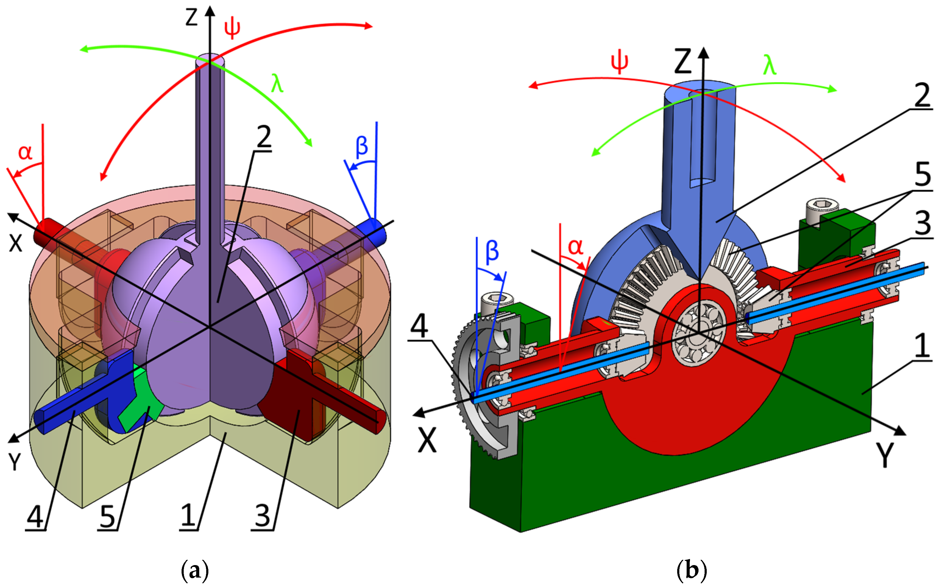
Figure 2b. The force feedback system in this haptic device is useful in indicating the proximity to singular positions that appear in this manipulator and to special areas of the workspace, where the mechanical energy is accumulated in the flexible bars and can be released in an uncontrollable way. In this kind of ultraflexible manipulator, when certain types of singular configurations are reached, an instability phenomenon occurs [30]. For instance, it occurs when the end-effector of the mechanism makes a rapid transition from one aspect of the workspace to the other. As the exact moment of this “release” is hard to predict based only on visual feedback, the force feedback system was introduced. This system generates force in order to resist the operator’s attempts to approach the “unsafe” workspace area. The force increases as the end-effector gets closer to the undesirable zone.
The second objective of the current research was to identify the optimal working mode for the proposed application of the haptic device. Two working modes were proposed for the parallel manipulator control: velocity mode and position mode. In the velocity mode, the controlled parameter is the velocity vector of the end-effector. In the position control mode, the position of the haptic device handle is directly related to some position of the end-effector within the workspace. It was expected that the velocity control mode could provide better precision, as it is less dependent on the operator’s skill and haptic device resolution; meanwhile, the position mode would be more intuitive and faster.

3.1. Experimental Task Planning

Testing haptic devices involves a large number of operators as the performance of the device depends on human skill. In different studies, the number of participants has ranged from 10 [31] to more than 50 [32]. The tasks that are usually performed during the tests can be divided into objective and subjective tasks. The objective tests results are normally numerical and can be easily subjected to any kind of statistical analysis without further preparation. The subjective test results are based on human opinion and in order to put them into a form suitable for numerical assessment, special questionnaires are used. The National Aeronautics and Space Administration Task Load Index Assessment (NASA TLX) [33] and After-Scenario Questionnaire—International Business Machines (ASQ IBM) [34] are the questionnaires that are normally used in haptic device research. In these questionnaires, the operator is asked to grade several aspects of the test. In NASA TLX seven questions with a scale from 0 to 20 are used, and in ASQ IBM three questions with a scale from 1 to 7 are used. The obtained grade can be used in statistical tests. Among the most widespread tests in studies of haptic devices are the analysis of variance (ANOVA) [35,36,37], the Mann–Whitney U test [38,39,40,41] and the Friedman test [42,43].
Considering the information provided, the requirements for the experiment were established. The group of testers should consist of 15–25 participants. The 2-RFR mechanism should be controlled in two modes: velocity and position. In order to obtain testers’ feedback, the NASA TLX questionnaire should be used, as it can provide more information.
In both working modes, a set of four tasks should be performed:
  • Defining the workspace boundaries/singular positions without force feedback.
  • Defining the workspace boundaries/singular positions with force feedback.
  • Execution of the proposed trajectory.
  • Following the leading object within a certain tolerance.
Of these tasks, the third and the fourth are the most important as they are intended to evaluate the general performance of all the haptic device parts and systems.
In addition, the reconfigurability should be tested by blocking one of the DOFs of the proposed joints. It was expected that this feature could provide precise straight motion in a horizontal or vertical direction, depending on the experimental setup. As this test produces a positive or negative result, it was decided that it would not be included in the tasks performed by the group of testers.
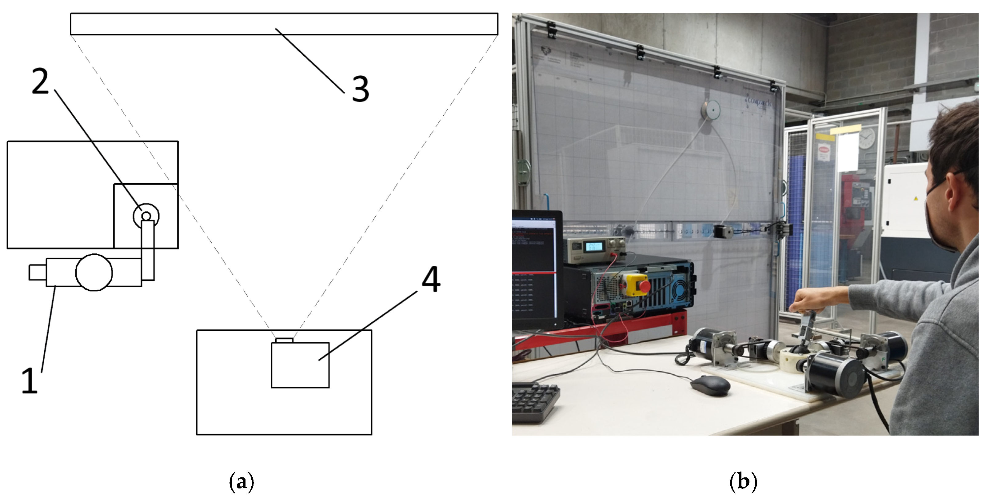
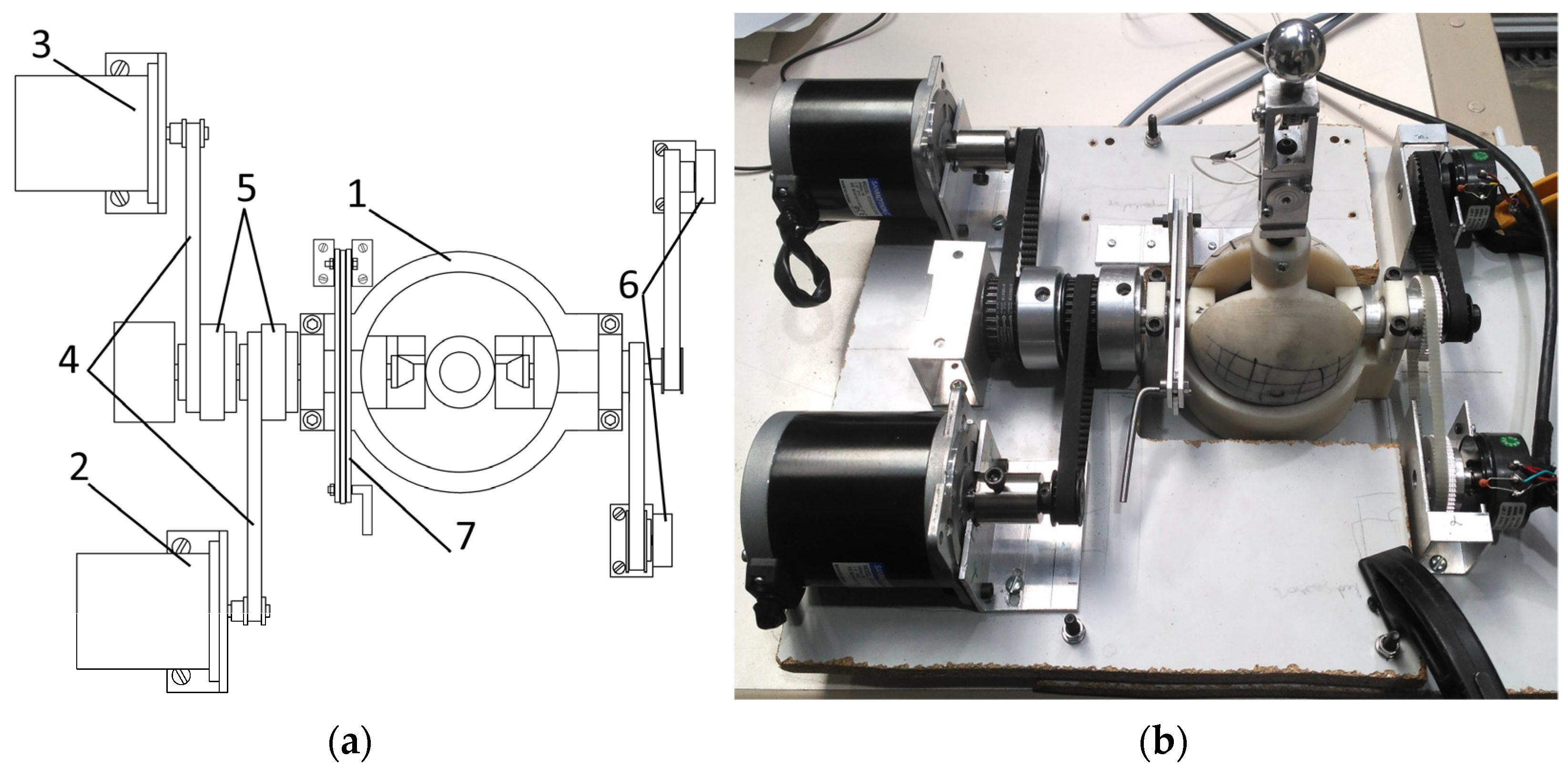
As the tasks require the visualization of different images (trajectory line, moving object) on the background of the controlled parallel mechanism, a digital projector was used. A schematic representation of the experimental setup is presented in 
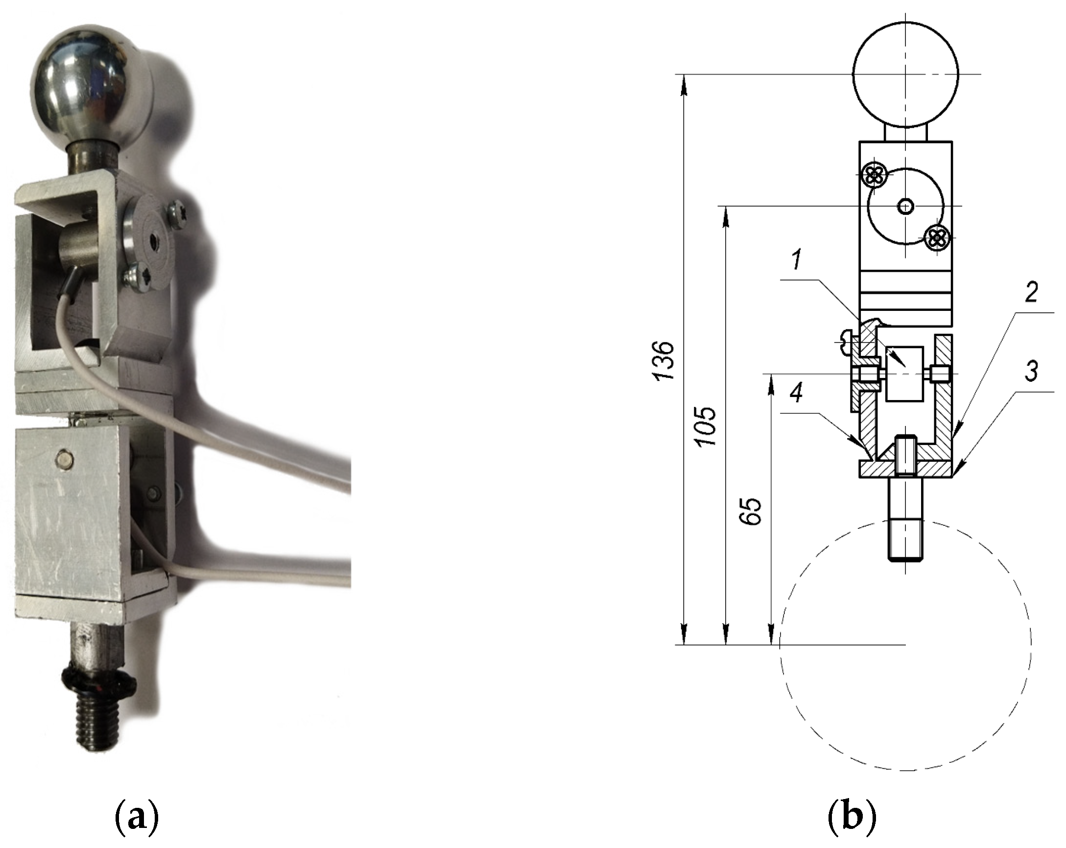
Figure 2a. The operator 1 holds the handle of the haptic device 2 and looks at the 2-RFR parallel manipulator 3, where the image corresponding to the current task is projected with the projector 4. In the Figure 2b the real experimental arrangement can be seen.
The main goal of tasks one and two was to estimate the performance of the force feedback system. It was necessary to draw conclusions on how helpful this system is for the operator. The second objective of these tasks was to introduce the testers to the haptic device controls. In the first test, the operator was asked to find the workspace limits intuitively, based only on visual feedback. In the second test the goal was the same; however, the force feedback system was turned on. As the workspace of the mechanism had a high amount of positions that were close to boundaries, several directions of end-effector motion were proposed for the operator: two vertical and two horizontal lines. This measure was also an attempt to save time. The operator was asked to choose. Starting with one of them, the operator moved the end effector along it until the boundary was reached, causing the end effector to stop. After that, the direction of motion should be changed to the opposite one. Once the first line was completed, the operator moved to the second line. When the test was completed, the operator was asked to fill out a NASA TLX form, where in the “Performance” section he/she was prompted to assess how successful he/she was in predicting the workspace border.
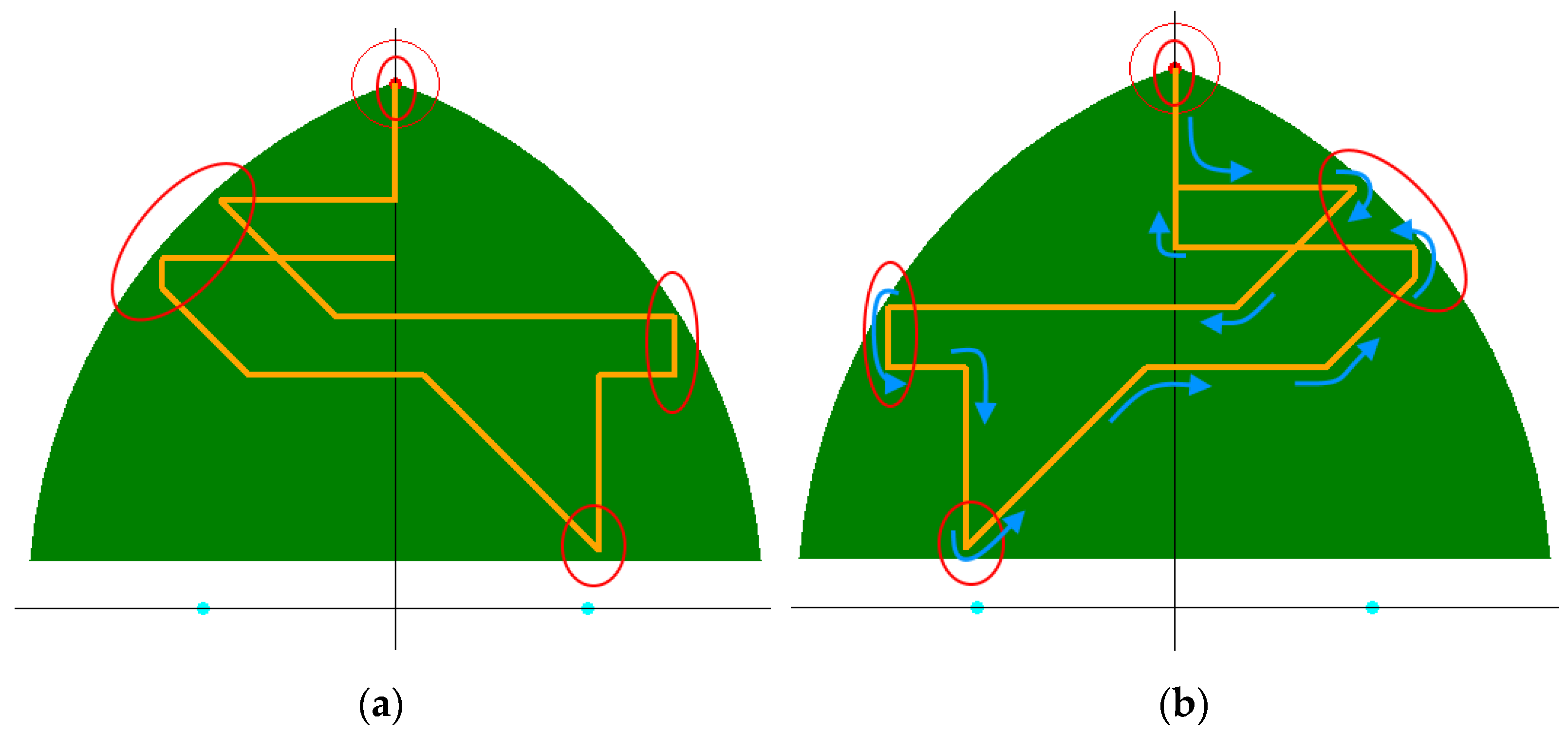
In task three, the accuracy of the control was assessed. The operator was asked to complete a predefined trajectory (indicated in orange in Figure 3a).
The tester could see only the trajectory, but not the workspace (shown in green in Figure 3a) or the parts of the trajectory that were close to the workspace border (shown in red ovals in 
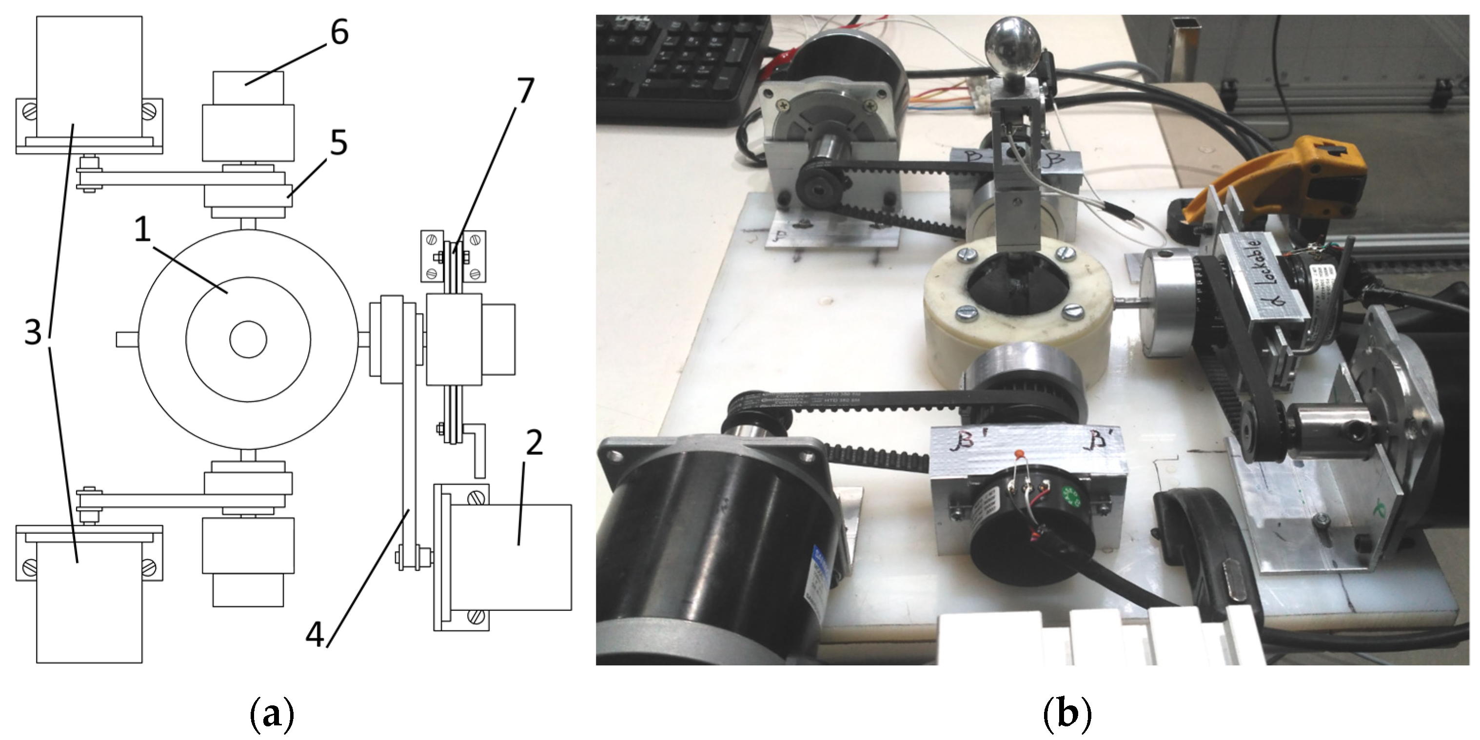
Figure 3a). The coordinates of the beginning and the end of the trajectory were (0, 90) cm and (0, 60) cm, respectively. There was no time limit in this task; the operator was to complete the trajectory as precisely as he/she was able to do. The task execution was filmed for further evaluation. The grading process involved counting the number of deviations from the proposed trajectory. It was decided that for the simplicity of counting, a deviation was defined as a case when the trajectory line left the borders of the CD disk that was attached to the end-effector of the 2-RFR mechanism (see Figure 2b). The radius of the standard CD disk is 6 cm; thus, this is the maximum distance between the trajectory line and the end-effector, and this was not counted as a deviation.
In task four, the tester followed the moving object within a certain tolerance. The main objective of this task was to evaluate the controllability of the haptic device in rapidly changing conditions. The task was assessed based on the precision of its execution. The moving object was a red dot with a red circle around it. The trajectory of the motion (shown in orange) of this object is presented in Figure 3b, with the direction of motion indicated in blue arrows. The first and last points of the trajectory coincided at (0, 90).
During the test, the operator could only see the moving object. In the beginning, the end effector and the object stayed at the same point. When the test started, the operator needed to keep the center of the end-effector within the red circle of the moving object, which had a radius of 10 cm. The velocity of the object was in the range of 1–4 cm/s.
The execution of this task was also filmed for further evaluation. The number of cases when the center of the end-effector went out of the circle was counted. In order to make the results of all the tests uniform, tasks three and four were graded from 0 to 20. Here, 20 is the maximum number of deviations, representing a complete failure, and 0 represents a perfect result. If the amount of deviations exceeds 20, the maximum number is assigned.

3.2. Statistical Tools

In order to process the large amount of data that were obtained during the experiment, statistical analysis tools were used. These tools can indicate if the difference between compared sample means is statistically significant. In order to do this, the probability of means being the same is calculated. If this probability is smaller than a certain number α , the difference between the sample means is considered to be significant. In most cases a value of α equal 0.05 [44] is acceptable.
In order to select proper statistical tools, the analyzed data distribution type should be identified. If the data have a normal distribution, parametric methods should be used; in the other case, or when the samples have a mixed data type—non-parametric methods should be used. The normality check can be implemented in two ways—graphical and numerical. The graphical method consists of a comparison of the sample distribution graph with the normal distribution graph. It is simple and fast; however, in some cases it cannot provide a definite result. The numerical methods are more reliable and provide definite results. There are many variations of numerical normality checks. In this study, the Shapiro–Wilk test was used as it provides higher statistical power [45,46] than the most commonly used Kolmogorov–Smirnov test (KS-test) [47]. The Shapiro-Wilk test can be defined as
W = ( i = 1 n a i x ( i ) ) 2 i = 1 n ( x i x ¯ ) 2
where x ( i ) is the i -th smallest value of the sample (not to be confused with x i , the i -th value of the sample); a i is a coefficient, taken from the special tables related to this test; and x ¯ is the sample mean.
In this test, the null hypothesis, or the first assumption, was that the studied sample had a normal distribution. If the value of W that was obtained from the calculation exceeds the critical value appropriate for the test, the null hypothesis has to be rejected and the data distribution is not normal. The critical value is taken from special tables, depending on the sample size and the value of α .
In this study, the tasks required the analysis of two samples at a time, which was accomplished using paired and unpaired t-tests for data with a normal distribution and Wilcoxon’s signed rank test and tge Mann–Whitney test for the mixed and non-normally distributed data [48]. In the comparisons which involved samples with interconnected data (such as tasks 1 and 2, the control mode comparisons), the paired t-test and Wilcoxon’s signed rank test were used. In cases where data did not have any connection (joint performance comparison), the unpaired t-test and the Mann–Whitney test were used.

4. Experimental Setup Design

4.1. Mechanical Design

The haptic device was used to control the 2-RFR ultraflexible planar manipulator, developed by our CompMech research group (see Figure 2b). The manipulator consisted of two flexible nylon bars with active revolute joints on one side and a passive revolute joint in the end-effector. Two Nema 32-sized stepper motors were used as the actuators. The manipulator was placed between two acrylic sheets (transparent in the front and white in the back) that were attached to a square frame with a 2 m side, made of an aluminum profile. The rear acrylic sheet had a coordinate mesh of 10 cm in size for better visualization of the end-effector position. This 2-RFR manipulator was kinematically equivalent to a 5-bar mechanism; however, it was more “human friendly” as it was safer due to the flexible nature of its bars.
The joint prototypes were manufactured using fused deposition modeling 3D printing technology. The material of the majority of the printed parts was acrylonitrile butadiene styrene (ABS). The rest of the printed parts were manufactured with Onyx from the Markforged company. Both reconfigurable joints are used in the proposed haptic device in a joystick mode. A schematic representation of the 2R spherical mechanism-based joint and its practical implementation is presented in Figure 4. The setup was built around joint 1, which was connected to force feedback actuators 2 and 3 through the belt gears 4 and special torque-generating bushings 5. The absolute rotary encoders 6 determined the current handle position. The clamp 7 was able to lock one DOF of the joint in order to provide precise horizontal motion.
In the proposed setup, stepper motors were used as actuators of the force feedback system. In order to transform steps into torque, special bushings (5 in Figure 4) were designed (see Figure 5a). The bushing consisted of inner 1 and outer 2 drums. The inner drum was connected to the input shaft of the joint. The outer drum was connected to the pulley 3 and was able to turn around the inner drum within a certain range. There were two springs 4 between the drums, of which one side was placed in the slots of the inner drum and the other side was pressing on the metal partition 5 that was fixed on the outer drum. When the drums rotated with respect to each other, the compression of the springs created an output torque. This happened when the handle was fixed in a certain position and the actuators of the force feedback system were turning.
The reconfiguration ability of the proposed haptic device was implemented by means of a manual clamp (see Figure 5b). The clamp contains three aluminum strips 1 (in Figure 5b one is removed for better visibility) of 4 mm in thickness, that can move around the axle 2, when the eccentric 3 is turned with the handle 4. In this moment, the upper strips are pressing upon the bushing 5, which connects the rotary encoder to the joint shaft to the lower strip, thus preventing it from rotation.
The handle of the haptic device and its scheme are presented in Figure 6.
The handle contained two tension-compression load cell sensors that were placed in two equal modules made of aluminum profile. The sensor 1 was fixed between the static part 2 of the module, and the moveable part 3. The moveable part can bend due to the slot 4. This design is intended to prevent the sensor from taking on non-axial loads that can damage it. Knowing the distances (see Figure 5b) from the center of the joint sphere (in dashed line in Figure 5b) to the sensors and the center of the handle ball, it is possible to calculate the forces acting on the handle.
The experimental setup built for the differential gear-based joint design (see Figure 7) was similar to the previous one and had several common elements. The joint 1 was placed in the center of the haptic device. Its force feedback system was driven with the actuators 2 and 3 through the belt drives 4 and torque-generating bushings 5. The encoders 6 in this setup are placed on the opposite side to the actuators and are belt-driven. The clamp 7 is situated on the left side, locking the vertical DOF of the joint.

4.2. Software and Electronic Hardware Design

The haptic devices were operated by Raspberry Pi 3B, with Xubuntu 18.04 LTS. It was handling low-level controllers, implemented with two Arduino Due boards (one for the actuators and another for sensors). The actuator Arduino board was connected to 5 (4 in the differential gear based joint design) Geckodrive G201X stepper motor drivers that controlled 3 (2) stepper motors of the haptic device and two stepper motors of the 2-RFR mechanism. The other Arduino board was obtaining information from Gefran PS-20 absolute rotary encoders and the ELAF-T1M-250N force sensors that were installed in the handle.
The controlling software was written in the Python programming language. The Robot Operating System (ROS) Melodic Morenia was used to organize and connect the parts of the system. ROS has a modular structure with nodes as modules that communicate with each other by sending messages through topics. In Figure 8, the structure of the control system is presented. Here the nodes are depicted as rectangles and the topics as arrows. Depending on the arrow direction, the communication is unidirectional or bidirectional.

5. Experimental Progress and Results

The number of participants was 17 for the active 2R spherical mechanism-based joint and 19 for the differential gear-based joint design. Nine participants were testing both experimental setups.
The data from the processed NASA TLX forms are presented in Appendix A (see Table A1 and Table A2). The results of the normality check and the selection of the appropriate statistical tools are presented in Appendix B (see Table A3, Table A4, Table A5, Table A6 and Table A7). Two videos, demonstrating the execution of the experimental tasks 3 and 4 in the velocity control mode are presented in the Supplementary Materials.
After the execution of the four tasks, the functioning of the reconfiguration ability in the haptic device was tested. In both experimental setups the clamp was locked manually in a desired position. In that position, the horizontal motion was tested. The handle was operated in such a way that the end-effector moved from the central part of the workspace towards one of the borders. When the border was reached (and the mechanism stopped), the handle was moved in the opposite direction until the other side of the border was reached. All the motion was strictly horizontal, which was confirmed visually and by the coordinate Y values in the ROS messages. The force feedback in the Y-axis was also completely locked mechanically by the clamp and did not interfere with the motion. The reconfigurability was tested in both working modes with similar results. Thus, the reconfigurability of the proposed haptic device was successfully confirmed.
The results of the statistical tests are presented in Table 1, Table 2 and Table 3.

6. Discussion on Haptic Device Test Results

6.1. Force Feedback System Evaluation

It can be seen from Table 1 that the experimental results in tasks one and two showed no statistically significant differences in both control modes. After thorough analysis of the NASA TLX forms, it was concluded that the main possible reason for this was that some of the testers misunderstood the grading principle. It was found by comparing the grade in the “Performance” part of the form with the written feedback that some of the testers left for the task. In several cases, the written feedback was positive; however the grade for task 2 was lower than for task 1. As an example, tester number 13 in the active 2R spherical mechanism-based joint test, task 1 left feedback saying: “It is complex to predict the end of the border”. The feedback corresponding to the second task was: “I feel more comfortable in the second task because I know better how it works and the force feedback helps too”. The grades for tasks one and two were 15 and 17, respectively. However, in the NASA TLX form, the worst result has the highest grade.
The other reason was that for some people the value of force produced by the device was too high. This was indicated in the “Physical demand” and “Effort” parts of the NASA TLX form. In addition, there was written feedback from testers that criticized the force level, for instance: “The force is very high to control it”, “The force is too strong” (Tester 6); “When you are reaching the limits, the feedback is a bit rough.” (Tester 14). The high value of force was necessary in order to make the force feedback easily recognizable and distinctive from the friction forces, induced in the mechanism of the joint. These friction forces were conditioned on the one hand by the joint kinematics, and on the other hand by the imperfections caused by the 3D printing manufacturing process of the joint prototypes.

6.2. Control Mode Comparison and Evaluation

The statistical analysis indicated (see Table 2) that there was a significant difference in the performance of the haptic devices in velocity and position control modes. As the difference was significant, it is possible to use the means of the data samples directly. It can be seen from Table A1 and Table A2 of Appendix A that the means of the data samples that corresponded to the velocity control mode were significantly smaller. Thus, the haptic device demonstrated better performance in the velocity mode. The survey conducted among the operators after the tests also indicated that the velocity control mode was preferable in most of the cases. The position control mode was preferred by the participants only in 17.6% cases for the active 2R spherical mechanism-based joint and in 5.3% cases for the differential gear-based design joint. Most of the written commentaries considered the velocity mode to be more convenient; however, some of the testers referred to the position control mode as “more intuitive”.
There are two main reasons why velocity control mode provided better performance than position control mode. The first is the resolution of the handle. As in the position mode, the angle of the handle inclination directly defines the position of the end-effector, even a small motion of the handle will affect the mechanism. From the hardware point of view there is no restriction on the possible resolution of the haptic device; however, there is such a limitation on the side of the operator. The human senses are not able to detect the small changes in the handle angles that can be sensed by the haptic device. This was especially important in the positions that are close to the workspace borders, as the force feedback was affecting the operators’ control on the device handle. The resisting force caused the small displacement of the handle and the mechanism reacted to it. Meanwhile the operator tried to adjust the handle by moving it further, which in its turn caused a stronger force response from the haptic device and the cycle repeated itself. This resulted in the oscillations of the end-effector and confusion of the operator. In addition, in the position mode, the velocity is not limited and the operator can reach the border of the workspace very quickly, experiencing a strong force response right away, without the phase of a smooth increase.
In the velocity control mode, the maximum velocity of the end-effector was limited to 5 cm/s, which gave the operator (and the system) time to react. When the end-effector of the mechanism approached the border, the transition of the force that resisted the operator was smooth and predictable. This made operation in the velocity control mode clearer for the majority of testers.
The second reason is the presence of clearances in the mechanism, due to the manufacturing technology that was used for the prototype. The position control mode is very sensitive to these clearances; however, in the velocity control mode, the difference between two velocities of the end-effector equals 10 ° of handle inclination, which is sufficient to compensate for any possible clearance. This problem can be eliminated by changing the joint manufacturing technology; however, it is caused by the first and the main problem of the excessive sensitivity of the haptic device in the position control mode. The sensitivity problem of the position mode, unfortunately, does not have a simple solution. In order to make the small changes in the handle inclination angle more significant for the operator, it is possible to increase the length of the handle. However, this will affect the overall dimensions of the haptic device and extend the range of the operator’s hand motion, making control of the haptic device inconvenient.
Considering the results of the statistical analysis and the testers’ feedback, the velocity control mode can be accepted as the most appropriate for the current haptic device design. It has been proven that it provides the best performance in the most common types of tasks for the haptic devices.

6.3. Joint Designs Assessment

According to the results of the statistical analysis, presented in Table 3, there is a significant difference in sample means in tasks 3 and 4 in the position control mode. The absence of differences in the results of these tasks in the velocity control mode indicates that the velocity control mode provided similar performance in both haptic devices.
Analyzing the means of the samples in tasks 3 and 4 (see Table A1 and Table A2 of Appendix A) it can be seen that the differential gear-based design joint provided smaller mean values in both tasks, which corresponds to better performance.
The worse performance of the active 2R spherical mechanism-based joint can be explained by its more complex kinematics. This joint has singular positions, one for each of the blue actuators (4 in Figure 1a). This takes place when the red actuator (3 in Figure 1a) is inclined ± 25 ° from the vertical position. In order to keep the joint in fcontrol, it is necessary to switch between the encoders that are connected to the blue shafts and between the two actuators of the force feedback system. However, due to the clearances in the joint, there is a difference in these two encoder readings. That difference causes a variation in the calculated angle that defines the horizontal displacement of the end-effector. The value of this angle can change in range of 3 ° 5 ° , which results in a big leap of the end-effector in the moment of switching between the encoders. As tasks 3 and 4 were focused on precision, this feature affected the device’s performance significantly.
The second reason is the high friction forces in certain positions of the blue actuators, which lead to jamming of the joint. This take place near the workspace border, when the force feedback generates a resisting force. In these cases, the additional force of the feedback increases friction and it becomes very hard for the operator to change the position of the handle. In the velocity control mode, these extreme positions in the active 2R spherical mechanism-based joint can be avoided by lowering the speed, but in the position control mode it is impossible. This disadvantage affected the execution of task 4, as it required precise and fast reactions from the operator.
The problem of clearances in the joint can be solved by using more precise manufacturing methods; however, the second problem is conditioned directly by the joint kinematics and cannot be solved easily.
In addition to the statistical analysis, the survey of the testers showed that 100% of the operators who participated in both haptic device tests chose the differential gear-based joint design as the best one.
It can be concluded that due to its simpler kinematics, the differential gear-based joint design demonstrated better performance than the active 2R spherical mechanism-based joint in a haptic device application.

7. Conclusions

It was confirmed that the tested joints were able to provide the reconfiguration ability for the haptic devices in which they were applied. The ability for precise horizontal motion of the controlled mechanism end-effector was successfully confirmed in both control modes with functioning force feedback.
The proposed haptic device designs were tested by two groups of operators. Four different tasks were executed in velocity and position-control modes. The two first tasks indicated a problem with the understanding of the grading principles among the participants and imperfections in the force feedback system of the haptic device. There are two possible solutions for this: performing more thorough explanations of the grading system to each participant before the test, or developing a customized and more intuitive form of grading.
It was found that the velocity control mode provided better performance in both joints and was preferred by the majority of the testers. This mode is less sensitive to the operators’ skills and provides better precision.
The performance analysis, together with the testers’ feedback, indicated that a differential gear-based joint design has substantial benefits in haptic device applications due to its kinematic simplicity. All nine testers who participated in both haptic device tests chose this joint design as the best one.
In conclusion, both joints can be used in haptic device systems in order to provide reconfigurability; however, the differential gear-based joint design provides simpler control and better performance.
As a possible direction of future work, several methods can be proposed for the improvement of reconfigurable haptic devices. First, the prototypes of the joints can be improved by using conventional manufacturing technologies, in order to be able to make them from metal and decrease the clearances and friction forces that are generated inside them. Second, the values of force created by the force feedback system should be adjusted and pre-testing should be conducted in order to confirm the correctness of the force values. Third, the actuators can be changed to DC motors in order to increase the frequency and the speed of response of the haptic device. Fourth, the preparation phase of the experiment should be improved through the introduction of a grading form which is easy to understand and is informative enough to provide the necessary test data. In addition, the proposed haptic devices will be used in a study of human–robot cooperation as controlling units. The performance of this means of control will be evaluated.

Supplementary Materials

The following supporting information can be downloaded at: https://www.mdpi.com/article/10.3390/app12010339/s1: two videos corresponding to the motion of the end-effector of 2-RFR ultraflexible mechanism in tasks 3 and 4 in velocity control mode are available.

Author Contributions

Conceptualization, M.R., V.P., M.U. and O.A.; formal analysis M.R.; investigation, M.R.; methodology, M.R.; project administration, V.P. and M.U.; resources O.A.; data curation, M.R.; software, M.R.; validation, M.R.; supervision, V.P. and M.U.; visualization, M.R.; writing—original draft, M.R.; writing—review and editing, V.P. and M.U.; funding acquisition, V.P. All authors have read and agreed to the published version of the manuscript.

Funding

The authors wish to acknowledge the financial support received from the Spanish Government through the Ministerio de Ciencia e Innovación (Project PID2020-116176GB-I00) financed by MCIN/AEI/10.13039/501100011033, and the support for the research group through Project IT949-16 provided by the Departamento de Educación, Política Lingüística y Cultura from the regional Basque Government.

Institutional Review Board Statement

Not applicable.

Informed Consent Statement

Not applicable.

Data Availability Statement

Not applicable.

Conflicts of Interest

The authors declare no conflict of interest.

Appendix A

Appendix A.1. Experimental Results

Appendix A.1.1. Active 2R Spherical Mechanism-Based Joint

Table A1. Grades taken from NASA TLX forms for the active 2R spherical mechanism-based joint tests.
Velocity ModePosition Mode
Tester №Task 1Task 2Task 3Task 4Task 1Task 2Task 3 Task 4
11611161212020
2780215142020
37113219122020
410136710102020
517150615182020
69122218172020
71366710162020
8151411014142020
932163162020
10680510112020
1110140318202020
121350219202020
1315173720182020
144101618202020
1518113920192020
1611315842020
172239022020
Mean10.359.531.825.5313.4713.6520.0020.00
Figure A1. An example of the experimental data: active 2R spherical mechanism-based joint, velocity control mode, task 2. Experimental data shown in blue, mean values shown in orange.
Applsci 12 00339 g0a1

Appendix A.1.2. Differential Gear-Based Design

Table A2. Grades taken from NASA TLX forms for the differential gear-based design joint tests.
VelocityPosition
Tester №Task1Task 2Task 3Task 4Task 1Task 2Task 3 Task 4
1620711171415
25702101159
395059449
4631514181011
5219101818128
617125417889
71126381120
8102276111014
9710248161120
1048031411814
11450268912
1210448351312
13410616171420
1433111211714
155435791020
16712231681820
1785041161220
18762715171020
1910823513715
Mean6.586.161.424.3210.5811.3710.1614.84
Figure A2. An example of the experimental data: differential gear-based design joint, velocity control mode, task 2. Experimental data showbn in blue, mean values shown in orange.
Applsci 12 00339 g0a2

Appendix B

Appendix B.1. Normality Test Results and Statistical Tool Selection

Appendix B.1.1. Normality Test Results

Table A3. Active 2R spherical mechanism-based joint sample distributions.
Velocity Control ModePosition Control Mode
Task12341234
Distribution typeNormalNormalNot normalNormalNormalNot normalNot normalNot normal
Table A4. Differential gear-based design joint sample distributions.
Velocity Control ModePosition Control Mode
Task12341234
Distribution typeNormalNot normalNot normalNormalNormalNormalNormalNot normal

Appendix B.1.2. Statistical Tool Selection

Table A5. Statistic tests for the evaluation of force feedback systems.
JointActive 2R Spherical Mechanism-Based JointDifferential Gear-Based Design
ModeVelocity ControlPosition ControlVelocity ControlPosition Control
Task12121212
TestPaired t-testWilcoxon’s signed rank testWilcoxon’s signed rank testPaired t-test
Table A6. Tests for control mode assessments.
JointActive 2R Spherical Mechanism-Based JointDifferential Gear-Based Design
Task234234
TestWilcoxon’s signed rank testWilcoxon’s signed rank test
Table A7. Tests to compare the performance of the joints.
ModeVelocity ControlPosition Control
Task234234
TestMann–Whitney U-testUnpaired t-testMann–Whitney U-test

References

  1. Lee, Y.; Lee, S.; Lee, D. Wearable Haptic Device for Stiffness Rendering of Virtual Objects in Augmented Reality. Appl. Sci. 2021, 11, 6932. [Google Scholar] [CrossRef]
  2. 3D SYSTEMS. Touch Haptic Device. 2020. Available online: https://www.3dsystems.com/haptics-devices/touch (accessed on 24 July 2020).
  3. Riabtsev, M.; Petuya, V.; Riera, A.; Macho, E. Design of an active reconfigurable 2R joint. Mech. Mach. Sci. 2019, 73, 1423–1429. [Google Scholar] [CrossRef]
  4. Sansanayuth, T.; Nilkhamhang, I.; Tungpimolrat, K. Teleoperation with inverse dynamics control for PHANToM Omni haptic device. SICE Annu. 2012, 2012, 2121–2126. [Google Scholar]
  5. Shin, E.C.; Ryu, J.H. Transmission of operator intention impedance using phantom haptic device. Ubiquitous Robot. Ambient Intell. 2014, 2014, 92–94. [Google Scholar] [CrossRef]
  6. Suleman, K.; Andersson, K.; Wikander, J. Dynamic based control strategy for haptic devices. In Proceedings of the 2011 IEEE World Haptics Conference, Istanbul, Turkey, 21–24 June 2011; pp. 131–136. [Google Scholar] [CrossRef]
  7. Hwang, Y.H.; Kang, S.R.; Cha, S.W.; Choi, S.B. An electrorheological spherical joint actuator for a haptic master with application to robot-assisted cutting surgery. Sens. Actuators A Phys. 2016, 249, 163–171. [Google Scholar] [CrossRef]
  8. Nishimura, N.; Leonardis, D.; Solazzi, M.; Frisoli, A.; Kajimoto, H. Wearable encounter-type haptic device with 2-DoF motion and vibration for presentation of friction. In Proceedings of the IEEE Haptics Symposium HAPTICS, Houston, TX, USA, 23–26 February 2014; Volume 14, pp. 303–306. [Google Scholar] [CrossRef]
  9. CyberGlove Systems. CyberTouch. 2017. Available online: http://www.cyberglovesystems.com/cybertouch (accessed on 27 July 2020).
  10. CyberGlove Systems. CyberTouch II. 2017. Available online: http://www.cyberglovesystems.com/cybertouch2/ (accessed on 27 July 2020).
  11. 3D SYSTEMS. Phantom Premium Haptic Devices. 2020. Available online: https://www.3dsystems.com/haptics-devices/3d-systems-phantom-premium (accessed on 24 July 2020).
  12. Hayward, V. Toward a seven axis haptic device. IEEE Int. Conf. Intell. Robot. Syst. 1995, 3, 133–139. [Google Scholar] [CrossRef]
  13. Salisbury, C.; Schwab, C.; Conti, F.; Salisbury, J.K. A 6-DoF Haptic Device for Microsurgery. 2007. Available online: https://web.stanford.edu/group/sailsbury_robotx/cgi-bin/salisbury_lab/?page_id=399 (accessed on 23 July 2020).
  14. HapticHouse. White Falcon 3D Touch Haptic Controller. 2020. Available online: https://hapticshouse.com/collections/frontpage/products/white-falcon-3d-touch-haptic-controller (accessed on 27 July 2020).
  15. Kim, S.; Ishii, M.; Koike, Y.; Sato, M. Haptic interface with 7 DOF using 8 strings: SPIDAR-G. In Proceedings of the 10th International Conference on Artificial Reality and Tele-existence, Orlando, FL, USA, 24–28 March 2000; pp. 224–230. [Google Scholar] [CrossRef]
  16. Ma, D.; Payandeh, T. Analysis and Experimental Study of a 4-DOF Haptic Device. Symposium on Haptic Interfaces for Virtual Environment and Teleoperator Systems. Reno, NV, USA, 13–14 March 2008; pp. 351–356. [Google Scholar] [CrossRef]
  17. Saafi, H.; Laribi, M.A.; Zeghloul, S. Redundantly actuated 3-RRR spherical parallel manipulator usedas a haptic device: Improving dexterity and eliminating singularity. Robotica 2015, 33, 1113–1130. [Google Scholar] [CrossRef]
  18. Grosch, P.; di Gregorio, R.; Lopez, J.; Thomas, F. Motion Planning for a Novel Reconfigurable Parallel Manipulatorwith Lockable Revolute Joints. IEEE Int. Conf. Robot. Autom. 2010, 11, 4697–4702. [Google Scholar] [CrossRef] [Green Version]
  19. Gan, D.; Dai, J.S.; Liao, Q. Mobility Change in Two Types of Metamorphic Parallel Mechanisms. J. Mech. Robot. 2009, 1, 041007. [Google Scholar] [CrossRef]
  20. Yan, H.-S.; Kuo, C.-H. Topological Representations and Characteristics of Variable Kinematic Joints. J. Mech. Des. 2006, 128, 384. [Google Scholar] [CrossRef]
  21. Pandey, V.; Hariskrishna, T.V. Novel Contact-Type Actuated Sphere for Powered Prosthetic-Ankle Joint. Procedia Comput. Sci. 2018, 133, 181–189. [Google Scholar] [CrossRef]
  22. Gewirts, J.; Halpern, J.R. Spherical gear. US9027441B2, 12 May 2015. [Google Scholar]
  23. Wu, K.C.; Melgoza, R. Spherical Robotic Shoulder Joint. U.S. Patent US5533418A, 9 July 1996. [Google Scholar]
  24. Abe, K.; Tadakuma, K.; Tadakuma, R. ABENICS: Active Ball Joint Mechanism with Three-DoF Based on Spherical Gear Meshings. IEEE Trans. Robot. 2021, 37, 1806–1825. [Google Scholar] [CrossRef]
  25. Yu, Y.; Narita, Y.; Harada, Y.; Nakao, T. Research of 3-DOF active rotational ball joint. In Proceedings of the 2009 IEEE/RSJ International Conference on Intelligent Robots and Systems, IROS 2009, St. Louis, MO, USA, 10–15 October 2009; pp. 5153–5158. [Google Scholar] [CrossRef]
  26. Palmieri, G.; Callegari, M.; Carbonari, L.; Palpacelli, M.C. Design and testing of a spherical parallel mini manipulator. In Proceedings of the MESA 2014-10th IEEE/ASME International Conference on Mechatronic and Embedded Systems and Applications, Senigallia, Italy, 10–12 September 2014. [Google Scholar] [CrossRef]
  27. Fan, Z.; Li, Z.; Jun, Z. Study on H8 Control of Active Magnetic Suspension Spherical Rotating Joint. In Proceedings of the 2016 3rd International Conference on Information Science and Control Engineering, Beijing, China, 8–10 July 2016; pp. 1141–1145. [Google Scholar] [CrossRef]
  28. Riabtsev, M.; Petuya, V.; Urízar, M.; Macho, E. Design and analysis of an active 2-DOF lockable joint. Mech. Based Des. Struct. Mach. 2020, 11, 1–25. [Google Scholar] [CrossRef]
  29. Riabtsev, M.; Petuya, V.; Riera, A. An Active/Passive Joint for Reconfiguration Applications. In Proceedings of the Fifth MeTrApp Conference 2019, Dalian, China, 9–11 October 2019; pp. 133–140. [Google Scholar] [CrossRef]
  30. Altuzarra, O.; Solanillas, D.M.; Amezua, E.; Petuya, V. Path analysis for hybrid rigid–flexible mechanisms. Mathematics 2021, 9, 1869. [Google Scholar] [CrossRef]
  31. Schleer, P.; Drobinsky, S.; Radermacher, K. Evaluation of Different Modes of Haptic Guidance for Robotic Surgery. IFAC-PapersOnLine 2019, 51, 97–103. [Google Scholar] [CrossRef]
  32. Luciano, C.J. Percutaneous Spinal Fixation Simulation with Virtual Reality and Haptics. Neurosurgery 2013, 72, A89–A96. [Google Scholar] [CrossRef] [Green Version]
  33. Chowriappa, A. Augmented-reality-based skills training for robot-assisted urethrovesical anastomosis: A multi-institutional randomised controlled trial. BJU Int. 2015, 115, 336–345. [Google Scholar] [CrossRef] [Green Version]
  34. Choi, K.S.; Chan, S.H.; Pang, W.M. Virtual suturing simulation based on commodity physics engine for medical learning. J. Med. Syst. 2012, 36, 1781–1793. [Google Scholar] [CrossRef]
  35. Christopher, A.M.L. Training surgical residents with a haptic robotic central venous catheterization. Physiol. Behav. 2016, 176, 100–106. [Google Scholar] [CrossRef]
  36. Roth, M.; Chellali, C.; Dumas, C.; Cao, G.L. Training effects of a visual aid on haptic sensitivity in a needle insertion task. Haptics Symp. 2012, 2012, 199–202. [Google Scholar] [CrossRef] [Green Version]
  37. McWilliams, L.A.; Malecha, A.; Langford, R.; Clutter, P. Comparisons of Cooperative-Based Versus Independent Learning While Using a Haptic Intravenous Simulator. Clin. Simul. Nurs. 2017, 13, 154–160. [Google Scholar] [CrossRef]
  38. Chellali, A.; Dumas, C.; Milleville-Pennel, I. Influences of haptic communication on a shared manual task. Interact. Comput. 2011, 23, 317–328. [Google Scholar] [CrossRef] [Green Version]
  39. Benyahia, S.; van Nguyen, D.; Chellali, A.; Otmane, S. Designing the user interface of a virtual needle insertion trainer. In Proceedings of the IHM 2015 Actes de la 27eme Conference Francophone sur l’Interaction Homme-Machine, Toulouse, France, 27–30 October 2015. [Google Scholar] [CrossRef] [Green Version]
  40. Nguyen, D.V.; Lakhal, S.B.; Chellali, A. Preliminary evaluation of a virtual needle insertion training system. In Proceedings of the 2015 IEEE Virtual Reality Conference, VR 2015-Proceedings, Arles, France, 23–27 March 2015; pp. 247–248. [Google Scholar] [CrossRef] [Green Version]
  41. Ko, J.K.Y.; Cheung, V.Y.T.; Pun, T.C.; Tung, W.K. A Randomized Controlled Trial Comparing Trainee-Directed Virtual Reality Simulation Training and Box Trainer on the Acquisition of Laparoscopic Suturing Skills. J. Obstet. Gynaecol. Can. 2018, 40, 310–316. [Google Scholar] [CrossRef] [PubMed]
  42. Chan, W.Y. Learning ultrasound-guided needle insertion skills through an edutainment game. Lect. Notes Comput. Sci. 2010, 6250, 200–241. [Google Scholar] [CrossRef]
  43. Ni, D. A virtual reality simulator for ultrasound-guided biopsy training. IEEE Comput. Graph. Appl. 2011, 31, 36–48. [Google Scholar] [CrossRef]
  44. Leo, G.D.; Sardanelli, F. Statistical Significance: P Value, 0.05 Threshold, and Applications to Radiomics—Reasons for a Conservative Approach. Eur. Radiol. Exp. 2020, 4, 18. [Google Scholar] [CrossRef] [Green Version]
  45. Thode, H.C. Testing for Normality; CRC Press: Boca Raton, FL, USA, 2002; Volume 164. [Google Scholar] [CrossRef]
  46. Coin, D.; Corradetti, R. Tests for Normality: Comparison of Powers. Power 1933, 11, 177–180. [Google Scholar]
  47. Ghasemi, A.; Zahediasl, S. Normality tests for statistical analysis: A guide for non-statisticians. Int. J. Endocrinol. Metab. 2012, 10, 486–489. [Google Scholar] [CrossRef] [Green Version]
  48. Nahm, F.S. Nonparametric statistical tests for the continuous data: The basic concept and the practical use. Korean J. Anesthesiol. 2016, 69, 8–14. [Google Scholar] [CrossRef]
Figure 1. The reconfigurable joint designs: (a) an active 2R spherical mechanism-based joint; (b) differential gear-based joint.
Applsci 12 00339 g001
Figure 2. The experimental setup: (a) schematic representation (view from the top): 1 operator, 2 haptic device, 3 parallel manipulator, 4 projector; (b) real implementation (projector is turned off).
Applsci 12 00339 g002
Figure 3. The trajectories (in orange) used in task three (a) and used in task four (b).
Applsci 12 00339 g003
Figure 4. Haptic device with the active 2R spherical mechanism-based joint: (a) schematic representation: 1 the joint; 2 and 3 stepper motors; 4 belt drive; 5 step-to-torque transforming bushing; 6 rotary encoder; 7 clamping mechanism; (b) practical setup.
Applsci 12 00339 g004
Figure 5. Haptic device elements: (a) step-to-torque-transforming bushing: 1 inner drum, 2 outer drum, 3 pulley, 4 springs, 5 partition; (b) the clamping mechanism: 1 aluminum strips, 2 axle, 3 eccentric, 4 handle, 5 bushing of the joint.
Applsci 12 00339 g005
Figure 6. Haptic device handle: (a) practical implementation; (b) blueprints: 1 sensor, 2 static part of the sensor frame, 3 movable part of the sensor frame, 4 slot.
Applsci 12 00339 g006
Figure 7. Haptic device with the differential gear-based joint: (a) schematic representation: 1 the joint, 2 and 3 actuators, 4 belt drives, 5 step-to-torque-transforming bushing, 6 rotary encoder, 7 clamping mechanism; (b) real setup.
Applsci 12 00339 g007
Figure 8. Flowchart of the ROS node structure: nodes in rectangles; topics as arrows.
Applsci 12 00339 g008
Table 1. Results of the statistical analysis of tasks one and two in two control modes.
JointActive 2R Spherical Mechanism-Based JointDifferential Gear-Based Joint
Control ModeVelocityPositionVelocityPosition
Task12121212
Significant differenceNo No No No
Table 2. Results of the statistical analysis of the two control modes in tasks 2–3.
JointActive 2R Spherical Mechanism-Based JointDifferential Gear-Based Joint
Task234234
Significant differenceYesYesYesYesYesYes
Table 3. Results of the statistical analysis of the two joints performance in tasks 2–3.
ModeVelocity ControlPosition Control
Task3434
Significant differenceNoNoYesYes
Publisher’s Note: MDPI stays neutral with regard to jurisdictional claims in published maps and institutional affiliations.

