Article

Development of a Novel Omnidirectional Treadmill-Based Locomotion Interface Device with Running Capability

Integrated Institute of Technology, Gwangju Institute of Science and Technology (GIST), 123 Cheomdan-gwagiro, Buk-gu, Gwangju 61005, Korea
*
Author to whom correspondence should be addressed.
Appl. Sci. 2021, 11(9), 4223; https://doi.org/10.3390/app11094223
Submission received: 23 March 2021 / Revised: 30 April 2021 / Accepted: 3 May 2021 / Published: 6 May 2021
(This article belongs to the Special Issue Haptics for Tele-Communication and Tele-Training)

Abstract

:
To achieve an immersive virtual reality (VR) environment, omnidirectional treadmills (ODTs) allow users to perform locomotion in any direction. However, existing ODTs are heavy and complex, and operate at low speeds. This limits fast user motion and prevents natural interactions in real applications such as military training programs and interactive games. In this paper, we introduce a novel locomotion interface device with running capability, which uses an omnidirectional treadmill with a new power transmission mechanism and a locomotion controller that enables the user to make fast movements. As a result of the improved power transmission performance due to the simple and relatively lightweight structure, the proposed two-dimensional treadmill can generate a maximum speed of 3 m/s, with an acceleration of 3 m/s2. Moreover, through a pilot test with the proposed locomotion interface device, we verified that the fast directional changes during walking and running with the designed speed adaptation controller do not exceed the acceleration performance of the proposed system. Due to its wide range of movement speeds and acceleration capabilities, and lack of any motion constraints, the proposed locomotion interface device with a novel ODT can be used as a representative platform in various VR environments to enhance the immersive experience.

1. Introduction

A locomotion interface (LI) can support walking and running through appropriately generated ground surfaces to provide active participation in virtual environments (VEs) with realistic spatial sensations [1]. Therefore, an LI provides a sense of mobility based on energy input/consumption of actual walking [2]. To create more immersive locomotion, a LI system should allow the user to arbitrarily change not only the walking speed, but also the walking direction. Such features may motivate a user to participate more actively in VR experiences, such as military training programs, physical education programs, disaster preparedness training, and rehabilitation programs [3].
To simulate omnidirectional locomotion, several types of devices have been suggested, such as balls [4], large spheres [5], mobile robots [6], a rotating one-dimensional (1D) treadmill [7], and a robotic foot platform [8,9,10]. However, these devices have limitations with respect to omnidirectional walking. As the most natural mechanism for two-dimensional (2D) LI, an omnidirectional treadmill (ODT) can simulate the over-ground walking of humans [11,12,13]. An ODT or 2D treadmill usually consists of “unit segments” (transverse treadmills) installed in such a way as to form a continuous loop (Figure 1). Each unit segment is a narrow treadmill with its own belt.
In an ODT, as shown in Figure 1, the X-axis translational motion is generated by the rotation of all the unit segments along   A X vector, while the Y-axis translational motion is generated by rotational actuation of the belt of each segment along   A Y vector. Thus, the 2D treadmill combines small treadmills assembled orthogonally to create a single, large treadmill. An ODT provides an infinite ground plane by generating independent belt motions along two orthogonal axes (X and Y). In the cases of Cyberwalk [12] and Torus treadmill [14], Y-axis translational motion is generated by individual actuators attached directly to each unit segment. This increases the inertia of the segments; thus, this design requires a very large amount of power to rotate all the segments (X-axis motion). As the weight of each segment is increased, the acceleration performance is greatly reduced.
The ODTs developed by the United States Army Research Institute (US ARL) ODT [15] and the InfinaDeck treadmill [16] use a different mechanism to generate Y-axis motion. The transverse treadmill belt (segment belt) is actuated by stationary actuator(s) through a special transmission system. This design, due to the light weight of the individual segments, may improve the maximum speed and acceleration of the systems during X-axis translational motion as compared to those of the Cyberwalk and Torus treadmill. To drive each segment belt while allowing free movement in the X-axis direction, these ODTs use a frictional transmission mechanism composed of omni-wheels. However, since the omni-wheels-based frictional transmission mechanism has a low power transmission efficiency, the maximum speed and acceleration of these ODTs for Y-axis translational motion are limited. Thus, due to the high inertia of the unit segment treadmills for X-axis translational motion and the low efficiency of power transmission for Y-axis translational motion, the currently available 2D treadmills are only able to accommodate slow human walking speeds and accelerations. This limitation is the main obstacle in developing an immersive VR environment with fast and natural locomotion.
A further complexity in the design of a past paced ODT is that even after improving the power transmission efficiency for Y-axis motion and reducing the mass of moving components for X-axis motion, the actuation scheme of the ODT must be carefully designed to reduce structural stress in the ODT’s frame; additionally, the design should minimize energy loss from the actuators to the power transfer components during motor actuation.
In this study, we have developed a novel locomotion interface device, which is based on an omnidirectional treadmill with a transmission mechanism that is referred to as the geared omni-pulley (GOP). To overcome the limitations of conventional ODTs and to deal with the complexities of fast ODT design, the proposed locomotion interface device has the following capabilities: (1) X- and Y-axis translational motion generation through a novel gear-based power transmission mechanism; (2) a distributed power scheme in which two motors installed on each axis are synchronized using low-level synchronized motor control [17]; and (3) high-level feedback using robust integral of the sign of the error (RISE) control [18] to allow fast movements while changing the walking direction.
The remainder of the paper is organized as follows; the main design concepts for the locomotion interface device with high speed and acceleration are presented in Section 2, the high-level controller design for the proposed locomotion interface and pilot study results are in Section 3 and Section 4. Finally, the conclusions drawn are given in Section 5.

2. LI Device Design for Fast Motion

2.1. Actuation of Unit Segment Belt by Geared Transmission

For 2D treadmills, the main issue is how to actuate the segment belt for Y-axis motion. In Torus and Cyberwalk treadmills, as shown in Figure 2a, each segment requires a dedicated actuator, which increases the segment mass due to the inclusion of the actuating parts and thus makes it a disadvantageous design for implementing fast X-axis motion.
In the US ARL ODT (United States Army Research Laboratory Omnidirectional Treadmill), as shown in Figure 2b, a motor attached to the system frame can drive the segment belt through an omni-wheel-based power transmission mechanism. The power from the frame-fixed motor can be transmitted to the segment belt for Y-axis motion by the omni-wheels, while the rollers of the omni-wheels that are in contact with the segment belt passively rotate when the segments move along X-axis. This transmission is based on line–contact friction, which limits the ability of the segment belt to follow the fast movements of a user along Y-axis. To enhance the transmission efficiency of segment belt actuation, we propose the novel gear transmission method shown in Figure 2c to directly drive each segment belt [19]. Since the segment belts are driven by geared-pulleys, the transmission efficiency is significantly enhanced as compared to the frictional transmission by an omni-wheel. Moreover, the proposed concept is suitable to generate fast X-axis motion due to a lightweight platform with low segment mass/inertia.
The omnidirectional rack described in [20] may be considered a suitable mechanism for orthogonal translation motion. However, it is not appropriate for creating infinite ground because the rack gear is made using a rigid material, which is not flexible such as timing belt. The proposed transmission mechanism for Y-axis translation can use commercially available timing belts as segment belts (Standardized name: T10 Urethane belt, pitch specification: 10 mm).

2.2. Transmission Design for Omnidirectional Motion

Figure 1 and Figure 2c show the conceptual design of the proposed 2D translational motion with geared-pulley transmission. This simple holonomic design allows generation of infinite motion in both axes. In addition, this actuation method only drives the segment belts that are on the active surface where the user can locate and walk. This can reduce the required motor power as less than half of the segment belts are actuated at any given time. However, when the proposed mechanism creates 2-dimensional ground by actuating both X and Y axes, the coupled surfaces of the geared-pulleys and segment belts get frictional forces because the segment belt should also move in a direction perpendicular to the direction of the transmitted force of the input geared pulley. Thus, the geared pulley needs to be modified to include a passive rotation mechanism for reducing this friction. In this paper, we implement the Y-axis motion using a geared omni-pulley set (GOPS) equipped with toothed rollers instead of the conventional geared pulley, as shown in Figure 3a.
The design concept of GOPS is organized by an omni-wheel with gear. The high transmission efficiency of the gear is used for motion in the   A Y direction, while the friction on the tooth surface caused by motion in the   A X direction is reduced by the passive rotation of the toothed rollers, similar to an omni-wheel. The toothed roller for reducing the frictional force is designed by body of rotation of an involute toothed part of a normal geared pulley along the rotational vector N shown in Figure 3b. This rotational vector also represents the axis of the passive rotation of the toothed rollers when segments move along the X-axis.
In the presented system, the design of the GOPS uses the specifications of the commercial product called the T10 type geared pulley that works with the T10 Urethane belt. The parameters of the normal geared pulley, which are independent of the number of teeth, pitch (p = 10 mm), tooth height (th = 3.2 mm), tooth width (wh = 2.76 mm) and input angle of the tooth (λ = 25 deg). Moreover, GOPS design also considers the parameters depended on the number of teeth (Z = 36) such as radius of the pitch circle (rp = 57.295 mm), total radius (r = 56.375 mm) of the GOPS and the radius of the base circle (rb = 53.175 mm) because the frontal projection of the GOPS is identical to a normal geared-pulley profile.
Among the GOPS configuration parameters shown in Figure 3b, the number, n, of toothed rollers is the main determinant. Figure 4 shows the example of how to properly setup the GOPS configuration in the case that the number of toothed rollers is 6. The relationship between the total number of teeth (Z) and the number of toothed rollers (n) defines to the module of the GOPS (mGOP) as follows:
m G O P = Z / n ( n = 2 a 6 ,   a 3 ) ,   ( a , Z , n ,   m G O P ) ,
where a∈ℕ is a positive natural number greater than or equal to 3. Thus, mGOP represents the number of teeth in one toothed roller. It can also define an appropriate number for n because the number of teeth must be a natural number. All toothed rollers have an index number (ith) according to the range 1 ≤ i∈ℕn, as shown in Figure 4. Odd and even numbers in the toothed roller index (i) make up each separate geared omni-pulley (GOP) (see also Figure 3), and two GOPs are combined to form one GOPS.
In the design of GOPS, the total number of teeth (Z) of the GOPS is 36, and its 6 toothed rollers are configured with a uniform angular spacing of 60°. To configure the frontal projection of this GOPS according to the normal geared-pulley profile, one GOP is placed behind the other with a phase offset of 60° between the toothed rollers of both the GOPs.
Once the GOP arrangement is set, the next step is selecting the size of rroller as the GOPS design parameter, whose range is calculated by the general geared-pulley parameters (p, th, etc.) and the GOPS configuration parameter (n) that has already been determined. Due to the shape of the toothed roller, the radius at its end (rroller) is used to define its size. Moreover, rroller_thick is defined as the largest radius at the center of the toothed roller, as shown in the right-side image of Figure 4. rroller has the following range:
t h | sin ( π 1.5 n 1 n + p / 4 r p ) | < r r o l l e r < r 4 sin ( 2 π / n ) .
Thus, the minimum rroller is calculated to maintain the proper tooth shape, and its maximum size corresponds to the circumcenter point to avoid interference between the arrangements of each toothed roller installed in a GOP. The selected rroller defines the value of rroller_thick according to the following relationship:
r r o l l e r _ t h i c k = r r o l l e r + ( r | r sin ( π ( 1.5 n 1 ) / n ) | ) .
In the presented design, the value of rroller is 10.82 mm, which is selected considering the range of rroller calculated using Equation (2) (3.6~16.27 mm), and do is selected as 28.5 mm to avoid interference between the toothed rollers of the GOPs.

2.3. Realization of Stable Omnidirectional Motion

Figure 5a shows how the ODT can generate X-axis motion through segment rotation along   A X defined in Figure 1. The segments are pin-constrained to the rib of the X-axis drive chain. As compared to a timing belt mechanism [19], the chain mechanism improves the transmission efficiency of X-axis drive by allowing the precise positioning of each segment without collisions between segments at high speeds. In the unit segment (transverse treadmill) design with a timing belt driven using GOPS, the segment belt has been turned inside out so that the toothed side of the belt is coupled with the teeth of the GOPS, while a belt tensioner retains the segment belt tension. A frame-fixed motor(s) drives the segment timing belt continuously through the GOPS to achieve Y-axis motion, while allowing translational motion of segments along the X-axis through the passive rotation of the toothed rollers [19,21]. It should be noted that the number of contact teeth between one segment belt and one GOPS is set to be the same as mGOP.
When a segment belt enters the active surface, as shown in Figure 5b (See also Figure 1), a rotational speed mismatch occurs between the segment belt entering the active surface without GOPS coupling and the segment belts already in the active surface. Therefore, speed synchronization should be considered to prevent damage to the teeth, and to guarantee smooth gear coupling during the re-coupling stage.
For the proposed F-ODT, a speed synchronizer is used to accelerate the re-coupling segment belt in advance through frictional actuation. As a unit segment approaches the edge of the GOPS, a cone shaped synchronizer increases its belt speed to match that of the belts already coupled with the GOPS. Thus, the synchronizer minimizes the speed mismatch between the GOPS and the belt being recoupled.

2.4. Design of Actuation System for Desired Performance

When a human try to run or stop quickly during straight walking, a maximum acceleration of 3 m/s2 is generated [22]. Thus, the target performance of velocity and acceleration of the ODT were set to 3 m/s and 3 m/s2, respectively, to simulate running and stopping. To validate the target performance, dynamic analysis was performed using a commercial multibody dynamics software (ADAMS), as shown in Figure 6. To obtain realistic analysis results, the boundary conditions, including the mass and inertia, were set based on 3D modeling, gravity, the initial X-axis drive chain tension (3000 N) and the Coulomb friction due to contact between the segment belt and the Teflon-coated segment structure [19].
The X-axis motion simulation was done by actuating all 64 unit segments (total weight: 576 kg) and human mass (150 kg) through the rotation of the chain and sprocket, and Y-axis motion was performed with one segment among the 27 segment belts on the active surface loaded with 150 kg to simulate a human mass. The additional information of the proposed ODT is summarized in Table 1, which is used to determine the actuator power. The X-axis and Y-axis motor instantaneous powers required to maintain a speed of 3 m/s were determined to be 28 kW and 8 kW, with average values of 8.8 kW and 4.2 kW, respectively. Table 2 summarizes the power requirements for each axis actuation.
In the presented system, 3-rows of GOP shafts were installed to connect 6 GOPS per one segment, as shown in Figure 7a, to secure the performance of the geared-coupling between the segment and GOPS. Thus, this mechanism reduces the power concentration on the contacted teeth of a segment belt by increasing the number of the contacted teeth by 3 times. Therefore, it can guarantee the power transmission performance because the generated motor torque required to drive the segment belt is distributed over the 3-row GOP shaft. The motors (Motor1y, Motor2y) actuate the power transmission belts, which in turn drive the gearboxes. The gearboxes actuate timing belts for rotation of the 3 GOP shafts simultaneously as a mechanically coupled power transmission system. The actuation mechanism for the X-axis also uses a distributed power design, in which the four drive chains are mechanically coupled. In Figure 7b, Motor1x and Motor2x simultaneously actuate the drive chains by actuating the sprockets.
As the designed ODT requires (1) a power transmission mechanism for driving the 3-row GOP shafts simultaneously, (2) a chain-sprocket mechanism for constraining and carrying the segments, and (3) a frame stiffness suitable for high velocity and acceleration, the interior of the ODT has very limited space. Therefore, motion actuation along each axis is generated using two synchronized motors, as shown in Figure 7. Under this distributed actuation, the motors’ power can be distributed uniformly to all the power transmission components without excessive stress. Moreover, this actuation design provides comparatively faster command response than a single motor design [23].
Since the system uses a distributed power scheme, it is important to achieve precise speed control of both actuators to prevent damage to the power transmission components [17]. To simultaneously minimize the differences in speed and torque of both actuators, a cross-couple control scheme [24] was incorporated into the low-level control of the proposed ODT, as shown in Figure 8.
The low-level controller synchronizes the motor speeds according to the desired speed command (vci), where vc = [vcx, vcy]T is the desired speed of the active surface, and v1i and v2i correspond to the velocity of each motor, determined via encoder feedback with respect to the X or Y-axis, Tc1i and Tc2i are the torque values. Synchronization for reducing the difference of each motor’s speed (vvi) and torque (vTi) in each axis was achieved by proportional-derivative (PD) control, as follow:
v v i = C v i ( v 1 i , v 2 i ) = k P v i ( v 1 i v 2 i ) + k D v i d ( v 1 i v 2 i ) d t ,   i = X , Y ,
where kPv and kDv are the positive gains of the speed controller. The torque synchronization controller is also implemented using PD control, as follows:
v T i = C t i ( T c 1 i , T c 2 i ) = k P t i ( T c 1 i T c 2 i ) + k D t d ( T c 1 i T c 2 i ) d t ,   i = X , Y ,
where kPti and kDti are the positive gains of the torque synchronization controller, and Tc1i and Tc2i are the torque values for the control input of Cti. To secure control stability of the low-level controller, suitable gains were selected based on the Nyquist criterion by considering the backlash model [19,25]. In terms of the Nyquist criterion, the intersection shows a marginally stable condition, i.e., within 0.4 Hz. Regarding the gain of the controller, the X and Y values were set as; kPvi = 0.1 and 0.5, kDvi = 0.02 and 0.04, kPti = 0.2 and 0.4, and kDti = 0.08 and 0.1, respectively.

2.5. Fabricating the ODT and Verifying the Performance

The proposed ODT fabricated as shown in Figure 9 has the following major characteristics: (1) high transmission efficiency via the novel GOPS for driving the segment belts for Y-axis motion, (2) low-weight unit segments for fast X-axis motion, (3) distributed motor actuation to reduce the motion response time and the strain on transmission parts.
To verify the performance of the proposed ODT, we measured the maximum acceleration and velocity of the active surface. The motion command was given as a sinusoidal signal of a magnitude of 3 m/s at 0.16 Hz for generating the maximum acceleration of 3 m/s2. In addition, to verify the low-level controller, the velocity and torque transmitted from the motors were also measured.
Figure 10 shows the results of the maximum speed and acceleration. The root mean square (RMS) value of the speed difference was 0.0087 m/s for the Y-axis, and 0.0013 m/s for the X-axis, respectively, as shown in Figure 10a,c. Thus, the speed synchronization and command-following performance are considered to be stable. In the Y-axis case, the RMS value of the torque bias was 27%, while in the X-axis case, the RMS value of torque bias was 20%, as shown Figure 10b,d. Thus, the low-level controller can overcome the nonlinearities present in the power transfer process and adequately distribute the load to the motors while executing the motion commands. It can also adequately compensate for the torque difference.
In the maximum performance, both axes showed a torque requirement of about 1.75 times the rated motor capacity, due to the implicit friction of the real system. However, the servo motors guarantee operation at 200% of the rated torque capacity for a period of 5~10-min. Therefore, the system can safely achieve high velocities and accelerations exceeding 3 m/s and 3 m/s2, respectively.
Table 3 compares the specifications of the existing 2D treadmills and the proposed ODT. The proposed ODT has a workspace of 2.5 m × 2.5 m, which is sufficient for safe running and various other types of locomotion, such as crawling. It can achieve the higher velocities and accelerations than the others. Also, due to the use of the distributed actuation system, the overall system height is <64 cm.

3. LI Control for Omnidirectional Running

3.1. Design of High-Level Controller

For effective treadmill-based gait exercise, a user speed adaptation controller should converge to an intentional speed of a user fast and precisely [26]. Moreover, it should effectively compensate the position error from the reference position to prevent feet twisting within turning motions in 2D treadmill simulations [15]. This is because if a user performs a step turning while too away from the reference position, an excessively unintended motion of the active surface in ODT occurs in lateral direction.
To verify that the fast directional changes during walking and running is possible using to the proposed ODT by conducting turn walking, the high-level controller facilitating is designed by using the 1D treadmill system model shown in Figure 11. When walking or running, the position error is derived as follows [27]:
d ( x x d ) / d t = v c + v w ,   v ˙ c = a c ,
where x is the current user position with respect to the reference position, xd is the desired position, vw is the intentional velocity of the user, and vc and ac are the treadmill belt velocity and acceleration commands, respectively. In the model shown in Equation (6), vc is applied to the treadmill servo motors, where its dynamics are compensated by the low-level controller. To avoid sudden variations in belt acceleration, the dynamics are extended using ac. The final control input (vc) can be obtained by time-domain integration of ac. To maintain the user at the center position, the desired position (xd) is set to zero (i.e., xd = 0) and saturation is applied to vc to remove the oscillatory command due to the negative position error when a user does not intend to walk.
As shown in Figure 12, for expanding to the 2D treadmill model, the user should be able to maintain forward locomotion while changing the walking direction. Thus, the controller uses the measured user orientation angle (θ) to create the user coordinates (Xuser, Yuser). The Xuser-axis is set up along the anterior-posterior (AP) direction of the user’s body, and the Yuser-axis is along the medio-lateral (ML) direction. The walking intention ( v w ), referred to in treadmill coordinates, is converted to v w u s e r in the user coordinates. To interface with the walking intention v w u s e r , the control command v c u s e r = [ v c X ,   u s e r v c Y , u s e r ] T is generated by the high-level controller with respect to the user coordinates. Then, this control command is transformed into treadmill coordinates as v c . According to the adaptive treadmill controller, which can be considered to be a cascade system [28], the linear growth rate of the interconnection term and the convergence property represented by Equation (6) guarantee the stability of the entire system. Thus, the control command ( v c ) for interfacing with the 2D gait information is derived as follows:
v c = R z , θ v c u s e r = R z , θ ( v ^ w u s e r + μ u s e r ) ,
where R z , θ is the orientation matrix of the Z-axis according to the orientation of the user, μ u s e r is a continuous input using the RISE controller [29] to compensate for the user position error due to error in the estimation of v w , and v ^ w u s e r is the 2D feed-forward term based on the user’s coordinates, which is simply expanded from [27], as follows:
v ^ w u s e r = k o ( p u s e r - ξ ) ,   ξ ˙ = - v c u s e r + k o ( p u s e r - ξ ) ,
where p u s e r = [xuser, yuser]T represents the position error in the user coordinate system, ko R 2 × 2 is a diagonal positive constant matrix which determines the convergence rate of the observer output to the true value of v ^ w u s e r stably [30], and ξ is the state of the feed-forward term, Finally, the total control law including the feedback command ( μ u s e r ) in the user coordinate system can be derived as follows:
v c u s e r = v ^ w u s e r + k a 0 t q ( t ¯ ) d t ¯ + ( k s + I ) α 2 0 t p ˙ u s e r + α 1 p u s e r   d t ¯ + β 0 t sgn ( p ˙ u s e r + α 1 p u s e r ) d t ¯ ,
where α1 R 2 × 2 and ks R 2 × 2 are diagonal positive matrices, β, ka and α2  R are positive constants, and q is the error of the velocity command defined as v c u s e r R z , θ T v. The applied RISE control scheme for the uncertainty compensation reduces position error via a closed-loop system while guaranteeing stability and asymptotic convergence of the position error by the estimation property of the RISE control scheme with the applied observer [22]. Similar procedure of the high-level control design for a user-driven treadmill such as observer-based control is also performed in the other research [30].
Moreover, the stability issue by the applied saturation is eliminated by a supervisory algorithm which perform initializing to the integral term of the RISE controller when a user stays behind the reference position [22]. It also solves the chattering problem that usually affects sliding mode control (SMC) systems [29].
To apply the designed controller to the 2D treadmill, the dead zone should be defined with respect to the user’s ML direction (Yuser-axis), as shown in Figure 12. Although the user walks straight ahead, the waist shows a swaying motion in the ML direction. The ML motions of a user during walking can affect the treadmill controller by inducing a continuous response. In the study reported in [31], the maximum displacement of the body’s center of mass in ML direction was shown to range from 5.65–8.33 cm. Thus, the dead zone in the ML direction applied in the current work is ±4 cm.

3.2. Performance of Curvature Radius

An ODT allows for a curved path of locomotion by combined motion of the X and Y axes in the treadmill frame. It is necessary to determine the lowest radius of curvature of a user, which can be used as the performance index for changes in direction during locomotion [9]. This range can be obtained based on the linear and angular velocities of a user according to the acceleration limits of the proposed ODT. When a user changes direction at an arbitrary angular speed in the user coordinate frame, the velocity command, vc, in the treadmill frame can be approximated as follows:
v c ( t ) R z , θ v w u s e r , ( θ = θ ˙ t + θ i n i t i a l ) ,
where θ ˙ is the angular velocity of the user, θinitial is the initial user orientation angle, and v w u s e r is the user’s intended velocity that is assumed to be a positive real value along the Xuser-axis (see Figure 12). Therefore, the maximum velocity and acceleration that the ODT can generate relates to the intended velocity and the angular speed of a user as follows (here, θinitial = 0):
v c ( t ) = v w , g i v e n u s e r cos ( θ ˙ t ) i v w , g i v e n u s e r sin ( θ ˙ t ) j d v c d t = v w , g i v e n u s e r × | θ ˙ | 3 m / s 2   s . t .   v w , g i v e n u s e r 3 m / s
where i and j are the unit vectors along the Xuser and Yuser axes. If the intentional user velocity is less than 3 m/s and the proposed ODT has an acceleration limitation of 3 m/s2, the allowable range of the angular velocity θ ˙ of the user, shown in Figure 13a, can be calculated from Equation (11). Given that the intended velocity ( v w , g i v e n u s e r ) is not directly measurable and is instead an estimated value, the user’s travel trajectory ( L VR), defined in VR coordinates (XVR, YVR), can be calculated by integrating the vc into Equation (12), as follows:
L   V R ( t ) 0 t v c ( τ )   d τ = 0 t R Z ( θ ) v w u s e r ( τ )   d τ ,
Since L VR has arbitrary curved paths in the VR, the curvature radius of L VR can be calculated as follows:
r c = v c ( t ) 3 /   v c ( t ) × v ˙ c ( t ) = v c ( t )   /   | θ ˙ | ,
When a user changes direction without moving, their allowable angular velocity can be infinite. Faster user speeds tend to decrease the allowable range of angular velocity. From Equations (12) and (13), it is possible to determine the minimum radius of curvature of the proposed ODT corresponding to any acceleration (0.001–3 m/s2), as shown in Figure 13b. It should be noted that due to the limited acceleration performance defined in Equation (11), the minimum radius of curvature is dependent on both the user’s speed and the allowable angular velocity.

4. Pilot Study Results of Locomotion Interface Device with 2-Dimensional Running

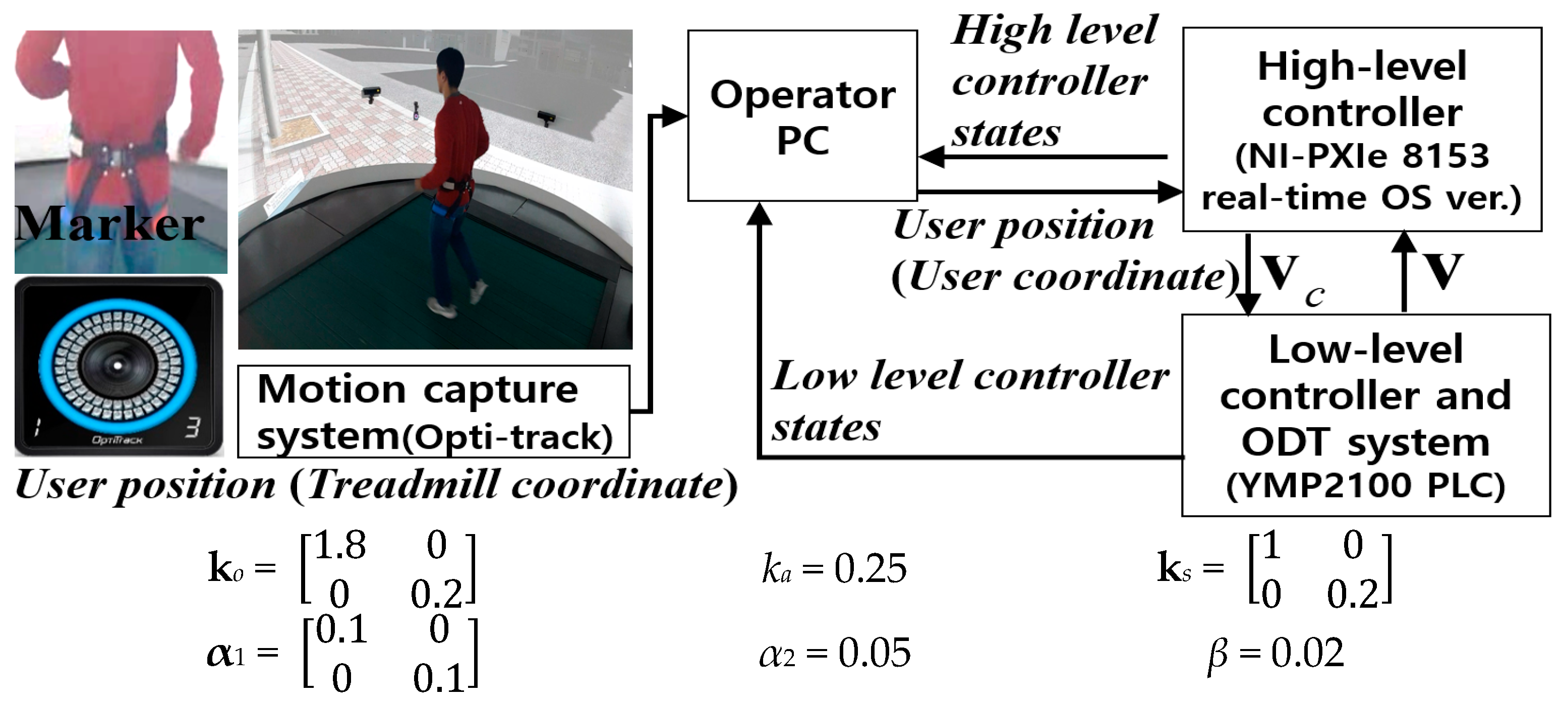
4.1. High-Level Controller Setup for Locomotion Interface

To interface the hardware components for the proposed high-level controller, we used a PXIe-8153 (National Instruments) and a personal computer (Intel i5-8400), as shown in Figure 14. The loop frequency of the high-level controller with the designed gain parameters was 1 kHz, and the motion capture system (VICON) frequency was 100 Hz to detect the user position precisely. The optical system can reduce hindrance to the user’s free locomotion on the treadmill and increase the freedom of the motion interface than wearable or attached sensor type due to allow free direction change.
The low-level controller used a programmable logic controller (MP2100; Yaskawa). Four markers were attached around the user’s waist to measure the position of the pelvis. The markers were positioned up to the posterior superior iliac spine to minimize the effects of the swaying motion of the waist.

4.2. Running Performance of High-Level Controller

The proposed high-level controller should be able to compensate the position error regardless of the user’s intended gait speed and changes in direction during running. Therefore, the pilot study of omnidirectional locomotion was carried out with one user (Sex: man, Age: 33) to verify acceleration performance of the proposed ODT with the designed controller. For this purpose, we asked the user to change direction by step turning, while running as fast as possible on the active surface of the ODT. In this study, we aimed to determine whether or not the ODT allows the user to perform omnidirectional locomotion while remaining unaffected by the acceleration limitations of the proposed system. Before starting the test, the user is briefed on how the system works, and the use was allowed to walk or run in the system for 10 min freely to familiarize how the system works. In the pilot test, the user completed three laps, generating a circular path in the VR environment. The running velocity was displayed on a 360° screen at 0° and 180° orientations in a spherical display surrounding the proposed ODT.
As shown in Figure 15a, the user achieved a gait speed of 1.8–2.8 m/s. The angular velocity filtered using a low-pass filter with a cut-off frequency of 1 Hz is shown in Figure 15b. The average angular velocity was 0.23 rad/s. Figure 15c shows the active surface speed of the ODT controlled by the low-level controller according to commands given by the high-level controller. As shown in Figure 15d, although the user performed rapid changes in direction during running, the maximum acceleration of the active surface was less than 1.1 m/s2. Thus, the proposed locomotion interface device can handle about 2.7 times the maximum acceleration achieved when a user changes direction while running at 1.8–2.8 m/s.
Figure 15e shows the user’s trajectory in the VR environment according to Equation (12). The average radius of the three virtual laps was calculated to be ~11.2 m, based on Figure 15f, which shows the radius of curvature r during the pilot study. The r is infinite at the beginning and end of running period due to the angular speed being zero. However, during omnidirectional running, r ranges from 6.1–35.7 m. As indicated by the solid red lines in Figure 15f, the local maximum radii of 29.3 m and 35.7 m occurred at 35 s and 69 s; when the user’s angular speed reached the local minimum values. The local minimum radii (dashed red lines) occurred at 21 s, 38 s, and 50 s when the user’s angular velocity was near its local maximum values. It should be noted that according to Equation (11), the acceleration value of the proposed ODT is proportional to the product of the user’s velocity and angular velocity. However, based on Equation (13), rc is proportional to the user’s speed and is inversely proportional to the angular velocity of the user.
Contrary to the Virtual Walking Machine [9], which aims to allow omnidirectional walking using two parallel robots, the proposed locomotion interface device does not have mechanical constraints with respect to the radius of curvature for omnidirectional locomotion. In addition, it allows for directional changes by the user, even during running, and has a sufficient acceleration capacity. Therefore, this study shows that the acceleration performance of the developed ODT is sufficient to handle high-speed (i.e., running) omnidirectional locomotion.
We also observed the position errors. The position errors are calculated by curve-fitting using the least squares method, as shown in Figure 16. The center of the ellipse is located within less than 0.05 m of the reference position, and the length of the long and short axis of the ellipse was about 0.36 m and 0.27 m, respectively. These magnitudes of position error did not affect to the user’s running, and the subject could successfully accomplish the omnidirectional running. Therefore, it can be concluded that the developed locomotion interface device with the proposed ODT can stay within the acceptable range of position error when the speed and orientation are changed dynamically.
About the user experience, the user remarked that the current environment including the proposed 2D treadmill and the spherical screen was able to provide a sense of space as the user could simultaneously see their actual lower limbs. However, the experiment with the proposed 2D treadmill and the designed high-level controller does not give the feeling of acceleration such as walking on real ground. When a user performs a walking motion, their actual absolute speed converges to 0 m/s due to the action of the high-level controller that works to maintain the user in the reference position. This behavior of a user-driven treadmill generates the anomalous force to the user. The cause of this phenomenon is defined well in [32]. For a gait interface to be as close as possible to walking on the ground, it is recommended that the rate of convergence to the user’s intended walking speed should be low. However, in the 2D treadmill, if the position robustness performance is not guaranteed due to the low convergence rate, the risk of a fall increases. Thus, for the safety of the user, in this work, we have focused on the walking interface performance rather than the close simulation of walking on the ground.

5. Conclusions

Here, we have introduced a novel ODT-based locomotion interface device with fast acceleration, based on a new power transmission concept and analyzing its design parameters. The power transmission efficiency of the Y-axis is greatly improved using a novel geared omni-pulley (GOP) transmission mechanism. Due to the use of this mechanism, the unit segments do not require dedicated actuators, thus reducing their weight and complexity. In the case of X-axis motion, high speed and acceleration can be achieved due to the relatively small mass and inertia values, and a simple structure. The proposed motor synchronization scheme for low-level control distributes the required load of the ODT among the motors for a fast response. Moreover, the high-level controller with the linear observer and RISE control allows a user to walk and run omnidirectionally, and the user position errors was within the range of about 0.36 m. Finally, we verified that fast directional changes by the user during walking and running do not exceed the acceleration limit of the system (3 m/s2). Thus, the developed locomotion interface with the fast ODT is expected to serve as a representative VR interface device for normal walking and running, with many potential applications. In future works, an intelligent controller will be designed to provide an immersive VR experience by simulating more complex types of locomotion, such as quick turning, side stepping, and backward walking. Furthermore, in the future works, it is planned to conduct User Experience Questionnaire (UEQ) with the more users for a qualitative evaluation of the feeling of the subjects who have an experience of gait interface with the proposed system.

Author Contributions

Conceptualization, S.P. and J.Y.; methodology, S.P.; software, S.P.; validation, S.P., H.L. and J.Y.; formal analysis, S.P.; investigation, S.P.; resources, S.P.; data curation, H.L.; writing—original draft preparation, S.P.; writing—review and editing, S.P. and J.Y.; visualization, S.P.; supervision, J.Y.; project administration, H.L.; funding acquisition, J.Y. All authors have read and agreed to the published version of the manuscript.

Funding

This research was funded by National Research Foundation (NRF) of Korea (2019M3C1B8090798) and GIST Research Institute (GRI) grant funded by the GIST in 2021.

Institutional Review Board Statement

Not applicable.

Informed Consent Statement

Informed consent was obtained from all subjects involved in the study.

Data Availability Statement

Not applicable.

Acknowledgments

The authors thank Tae-Ye Moon of CEO in Korea CNC Co. Ltd. for manufacturing the proposed 2D treadmill.

Conflicts of Interest

The authors declare no conflict of interest.

References

  1. Hejrati, B.; Crandall, K.L.; Hollerbach, J.M.; Abbott, J.J. Kinesthetic force feedback and belt control for the treadport locomotion interface. IEEE Trans. Haptics 2015, 8, 176–187. [Google Scholar] [CrossRef] [PubMed]
  2. Lichtenstein, L.; Barabas, J.; Woods, R.L.; Peli, E. A feedback-controlled interface for treadmill locomotion in virtual environments. ACM Trans. Appl. Percept. (Tap) 2007, 4, 7-es. [Google Scholar] [CrossRef] [PubMed] [Green Version]
  3. Boboc, R.G.; Toma, M.I.; Moga, H.; Panfir, A.N.; Talabă, D. An Omnidirectional System for Navigation in Virtual Environments. In Proceedings of the Doctoral Conference on Computing, Electrical and Industrial Systems, Berlin, Germany, 15–17 April 2013; pp. 192–199. [Google Scholar]
  4. Schwaiger, M.C.; Thummel, T.; Ulbrich, H. A 2d-motion platform: The cybercarpet. In Proceedings of the IEEE Second Joint EuroHaptics Conference and Symposium on Haptic Interfaces for Virtual Environment and Teleoperator Systems (WHC’07), Tsukuba, Japan, 22–24 March 2007; pp. 415–420. [Google Scholar]
  5. Fernandes, K.J.; Raja, V.; Eyre, J. Cybersphere: The fully immersive spherical projection system. Commun. ACM 2003, 46, 141–146. [Google Scholar] [CrossRef]
  6. Iwata, H.; Yano, H.; Fukushima, H.; Noma, H. CirculaFloor locomotion interface. IEEE Comput. Graph. Appl. 2005, 25, 64–67. [Google Scholar] [CrossRef] [PubMed]
  7. Patel, K.K.; Vij, S.K. Locomotion interface to the virtual environment to acquire spatial knowledge. In Proceedings of the TENCON 2008 IEEE Region 10 Conference, Hyderabad, India, 19–21 November 2008; pp. 1–4. [Google Scholar]
  8. Yoon, J.; Ryu, J. A novel locomotion interface with two 6-dof parallel manipulators that allows human walking on various virtual terrains. Int. J. Robot. Res. (IJRR) 2006, 25, 689–708. [Google Scholar] [CrossRef]
  9. Yoon, J.; Park, J.; Ryu, J. A Planar Symmetric Walking Cancellation Algorithm for a Foot—Platform Locomotion Interface. Int. J. Robot. Res. (IJRR) 2010, 29, 39–59. [Google Scholar] [CrossRef]
  10. Yoon, J.; Novandy, B.; Yoon, C.H.; Park, K.J. A 6-DOF gait rehabilitation robot with upper and lower limb connections that allows walking velocity updates on various terrains. IEEE/ASME Trans. Mechatron. (TMECH) 2010, 15, 201–215. [Google Scholar] [CrossRef]
  11. Darken, R.P.; Cockayne, W.R.; Carmein, D. The omni-directional treadmill: A locomotion device for virtual worlds. In Proceedings of the UIST 97, Banff, AB, Canada, 14–17 October 1997; pp. 213–221. [Google Scholar]
  12. Schwaiger, M.; Thuimmel, T.; Ulbrich, H. Cyberwalk: An advanced prototype of a belt array platform. In Proceedings of the IEEE International Workshop on Haptic, Audio and Visual Environments and Games, Ottawa, ON, Canada, 12–14 October 2007; pp. 50–55. [Google Scholar]
  13. Crowell, H.P., III; Faughn, J.A.; Tran, P.K.; Wiley, P.W. Improvements in the Omni-Directional Treadmill: Summary Report and Recommendations for Future Development; Army Research Lab: Aberdeen Proving Ground, MD, USA, 2006. [Google Scholar]
  14. Iwata, H. Walking about virtual environments on an infinite floor. In Proceedings of the IEEE Virtual Reality (Cat. No. 99CB36316), Houston, TX, USA, 13–17 March 1999; pp. 286–293. [Google Scholar]
  15. Boynton, A.C.; Kehring, K.L.; White, T.L. Biomechanical and Physiological Validation of the Omni-Directional Treadmill Upgrade as a Mobility Platform for Immersive Environments; Army Research Lab: Aberdeen Proving Ground, MD, USA, 2011. [Google Scholar]
  16. Burger, G. Single Belt Omni Directional Treadmill. U.S. Patent No. 8,790,222, 29 July 2014. [Google Scholar]
  17. Yao, W.S.; Yang, F.Y.; Tsai, M.C. Modeling and control of twin parallel-axis linear servo mechanisms for high-speed machine tools. Int. J. Autom. Smart Technol. 2011, 1, 77–85. [Google Scholar] [CrossRef] [Green Version]
  18. Fischer, N.; Hughes, D.; Walters, P.; Schwartz, E.M.; Dixon, W.E. Nonlinear RISE-based control of an autonomous underwater vehicle. IEEE Trans. Robot. (TRO) 2014, 30, 845–852. [Google Scholar] [CrossRef] [Green Version]
  19. Pyo, S.H.; Lee, H.S.; Phu, B.M.; Park, S.J.; Yoon, J.W. Development of a Fast-Omnidirectional Treadmill (F-ODT) for Immersive Locomotion Interface. In Proceedings of the IEEE International Conference on Robotics and Automation (ICRA), Brisbane, QLD, Australia, 21–25 May 2018; pp. 760–766. [Google Scholar]
  20. Tadakuma, K.; Tadakuma, R.; Ioka, K.; Kudo, T.; Takagi, M.; Tsumaki, Y.; Higashimori, M.; Kaneko, M. Study on the omnidirectional driving gear mechanism. In Proceedings of the IEEE International Conference on Robotics and Automation (ICRA), Saint Paul, MN, USA, 14–18 May 2012; pp. 3531–3532. [Google Scholar]
  21. Lee, H.; Pyo, S.; Park, S.; Yoon, J. Design of the omni directional treadmill based on an omni-pulley mechanism. In Proceedings of the IEEE 13th International Conference on Ubiquitous Robots and Ambient Intelligence (URAI), Xi’an, China, 19–23 August 2016; pp. 889–894. [Google Scholar]
  22. Asl, H.J.; Pyo, S.H.; Yoon, J. An Intelligent Control Scheme to Facilitate Abrupt Stopping on Self-Adjustable Treadmills. In Proceedings of the IEEE International Conference on Robotics and Automation (ICRA), Brisbane, QLD, Australia, 21–25 May 2018; pp. 1639–1644. [Google Scholar]
  23. Zhao, D.Z.; Li, C.W.; Ren, J. Speed synchronization of multiple induction motors with adjacent cross-coupling control. IET Control Theory Appl. 2010, 4, 119–128. [Google Scholar] [CrossRef]
  24. Huo, F.; Poo, A.N. Improving contouring accuracy by using generalized cross-coupled control. Int. J. Mach. Tools Manuf. 2012, 63, 49–57. [Google Scholar] [CrossRef]
  25. Nordin, M.; Bodin, P.; Gutman, P.O. New Models and Identification Methods for Backlash and Gear Play; Adaptive Control of Nonsmooth Dynamic Systems: London, UK, 2001; pp. 1–30. [Google Scholar]
  26. Yoon, J.; Park, H.S.; Damiano, D.L. A novel walking speed estimation scheme and its application to treadmill control for gait rehabilitation. J. Neuroeng. Rehabil. 2012, 9, 1–13. [Google Scholar] [CrossRef] [PubMed] [Green Version]
  27. Souman, J.L.; Giordano, P.R.; Frissen, I.; De Luca, A.; Ernst, M.O. Making virtual walking real: Perceptual evaluation of a new treadmill control algorithm. ACM Trans. Appl. Percept. (TAP) 2010, 7, 1–14. [Google Scholar] [CrossRef]
  28. De Luca, A.; Mattone, R.; Giordano, P.R. Acceleration-level control of the CyberCarpet. In Proceedings of the IEEE International Conference on Robotics and Automation, Rome, Italy, 10–14 April 2007; pp. 2330–2335. [Google Scholar]
  29. Xian, B.; Dawson, D.M.; de Queiroz, M.S.; Chen, J. A continuous asymptotic tracking control strategy for uncertain nonlinear systems. IEEE Trans. Autom. Control. 2004, 49, 1206–1211. [Google Scholar] [CrossRef]
  30. Souman, J.L.; Giordano, P.R.; Schwaiger, M.; Frissen, I.; Thümmel, T.; Ulbrich, H.; De Luca, A.; Bülthoff, H.H.; Ernst, M.O. CyberWalk: Enabling unconstrained omnidirectional walking through virtual environments. ACM Trans. Appl. Percept. (TAP) 2011, 8, 1–22. [Google Scholar] [CrossRef]
  31. Orendurff, M.S.; Segal, A.D.; Klute, G.K.; Berge, J.S.; Rohr, E.S.; Kadel, N.J. The effect of walking speed on center of mass displacement. J. Rehabil. Res. Dev. 2004, 41, 829–834. [Google Scholar] [CrossRef] [PubMed] [Green Version]
  32. Kim, J.; Park, H.S.; Damiano, D.L. An interactive treadmill under a novel control scheme for simulating overground walking by reducing anomalous force. IEEE/ASME Trans. Mechatron. 2014, 20, 1491–1496. [Google Scholar] [CrossRef]
Figure 1. Omnidirectional treadmill (ODT) concept (see Figure 2 for the cross-sectional view), and the geared omni-pulley (GOP)-based actuation scheme of the proposed ODT to generate infinite 2D ground.
Applsci 11 04223 g001
Figure 2. Cross-sectional view of the Y-axis motion of a 2D treadmill (unit segment): (a) Transversal treadmill actuated directly by an actuator (Torus or Cyberwalk treadmill), (b) Frictional transmission mechanism based on the Omni-wheel via the frame-fixed motor (US army ODT), (c) The proposed mechanism based on gear-driven transmission via a frame-fixed motor.
Applsci 11 04223 g002
Figure 3. (a) GOPS design including toothed rollers, (b) The front projection of GOPS design with a normal geared-pulley parameter, and GOPS configuration with its geometric analysis.
Applsci 11 04223 g003
Figure 4. GOPS design parameters and range of toothed roller size.
Applsci 11 04223 g004
Figure 5. (a) Drive chain of segment treadmills for X-axis motion, (b) Design and operation of the synchronizer mechanism.
Applsci 11 04223 g005aApplsci 11 04223 g005b
Figure 6. Dynamics simulation for X and Y axes.
Applsci 11 04223 g006
Figure 7. Mechanically coupled actuation system design: power transmission mechanisms of (a) the Y-axis and (b) the X-axis.
Applsci 11 04223 g007
Figure 8. Low-level speed controller for motor synchronization.
Applsci 11 04223 g008
Figure 9. The developed ODT using GOP actuation on the active surface, distributed actuation, and the dynamics simulations results.
Applsci 11 04223 g009
Figure 10. Verification of the performance using a sinusoidal motion command for surface acceleration of 3 m/s2. (a) Y-axis speed synchronous performance, (b) Y-axis torque synchronous performance, (c) X-axis speed synchronous performance, and (d) X-axis torque synchronous performance.
Applsci 11 04223 g010
Figure 11. High-level LI controller for a 1D treadmill.
Applsci 11 04223 g011
Figure 12. Expansion of high-level LI controller; 2D locomotion control commands and the dead zone in the saturation direction of the motion command in the user coordinates.
Applsci 11 04223 g012
Figure 13. Performance analysis of the proposed 2D treadmill. (a) The allowable range of angular velocity, given the acceleration limitations of the 2D treadmill and the user velocity, and (b) The minimum radius of curvature based on the performance of the proposed ODT.
Applsci 11 04223 g013
Figure 14. System configuration and gain parameters of the high-level controller used to evaluate running performance.
Applsci 11 04223 g014
Figure 15. Pilot study results. (a) The control command v c u s e r of the high-level controller, (b) angular velocity θ of the user, (c) velocity command (vc) and the actual velocity (v) of the active surface in treadmill coordinates (X, Y), (d) magnitude of the acceleration generated by the treadmill, (e) trajectory of the user in virtual reality (VR) coordinates (XVR, YVR), and (f) the radius of curvature rc of the user.
Applsci 11 04223 g015aApplsci 11 04223 g015b
Figure 16. Position errors in time domain and their ellipse fitted graph in the treadmill coordinate.
Applsci 11 04223 g016
Table 1. The ODT Specifications for Dynamic Simulation.
ItemSpecifications
System frame dimensions2780 mm × 3310 mm × 640 mm
Active surface area2.5 m × 2.5 m
Unit segment dimensions100 mm × 2577 mm × 70.5 mm
Unit segment weight9 kg
Number of segments64 units
Number of active segments27 units
Number of GOPS in 1 GOP shaft54 units per 1 GOP shaft
Chain and timing beltX-axis drive chainY-axis segment belt
Pitch18.875 mm10 mm
Width9.4 mm96 mm
Actuation part specificationSprocketGOP shaft
Pitch diameter396.375 mm114.59 mm
The number of teeth2136
Table 2. Power Requirements.
AxisRequired Pulley TorqueRequired Pulley Angular VelocityPower
X1768 Nm (max.)15.63 rad/s28 kW (peak)
563 Nm (avg.)8.8 kW (nominal)
Y148.5 Nm (max.)52.35 rad/s8 kW (peak)
81 Nm (avg.)4.2 kW (nominal)
Table 3. Comparison with Existing 2D Treadmills.
Y-axis Drive
Mechanism
Active Surface Area/ThicknessActuator SpecificationMax. vel.
(km/h)
Max. acc. (m/s2)
US army ODT 1Frame stationery motor with omni-wheel1.3 × 1.3 m2
/0.46 m
X-axis4 kW (1 EA)7.2Under 1
Y-axis4 kW (1 EA)
Cyber WalkSegment attached motor6.5 × 6.5 m2
/1.5 m
X-axis40 kW (4 EA)7.20.5
Y-axis37.5 kW (25 EA)10.80.75
Torus treadmillSegment attached motor1 × 1 m2
/0.5 m
X-axis200 W (1 EA)4.31
Y-axis960 W (12 EA)4.30.8
Proposed ODTFrame stationery motor with GOPS 22.5 × 2.5 m2
/0.64 m
X-axis8.8 kW (2 EA)10.93
Y-axis5.8 kW (2 EA)10.93
ODT 1: omnidirectional treadmill, GOPS 2: geared omni-pulley set.
Publisher’s Note: MDPI stays neutral with regard to jurisdictional claims in published maps and institutional affiliations.

