Article

The Use of UAV with Infrared Camera and RFID for Airframe Condition Monitoring

Air Transport Department, University of Žilina, Univerzitná 1, 010 26 Žilina, Slovakia
*
Author to whom correspondence should be addressed.
Appl. Sci. 2021, 11(9), 3737; https://doi.org/10.3390/app11093737
Submission received: 18 March 2021 / Revised: 8 April 2021 / Accepted: 16 April 2021 / Published: 21 April 2021
(This article belongs to the Special Issue Intelligent Transportation Systems: Beyond Intelligent Vehicles)

Abstract

:
The new progressive smart technologies announced in the fourth industrial revolution in aviation—Aviation 4.0—represent new possibilities and big challenges in aircraft maintenance processes. The main benefit of these technologies is the possibility to monitor, transfer, store, and analyze huge datasets. Based on analysis outputs, there is a possibility to improve current preventive maintenance processes and implement predictive maintenance processes. These solutions lower the downtime, save manpower, and extend the components’ lifetime; thus, the maximum effectivity and safety is achieved. The article deals with the possible implementation of an unmanned aerial vehicle (UAV) with an infrared camera and Radio Frequency Identification (RFID) as two of the smart hangar technologies for airframe condition monitoring. The presented implementations of smart technologies follow up the specific results of a case study focused on trainer aircraft failure monitoring and its impact on maintenance strategy changes. The case study failure indexes show the critical parts of aircraft that are subjected to damage the most. The aim of the article was to justify the need for thorough monitoring of critical parts of the aircraft and then analyze and propose a more effective and the most suitable form of technical condition monitoring of aircraft critical parts. The article describes the whole process of visual inspection performed by an unmanned aerial vehicle (UAV) with an IR camera and its related processes; in addition, it covers the possible usage of RFID tags as a labeling tool supporting the visual inspection. The implementations criteria apply to the repair and overhaul small aircraft maintenance organization, and later, it can also increase operational efficiency. The final suggestions describe the possible usage of proposed solutions, their main benefits, and also the limitations of their implementations in maintenance of trainer aircraft.

1. Introduction

The ability to perform maintenance processes as fast as possible and with the shortest downtime are the main goals of every maintenance organization. Every machine with moving parts is subjected to wear and necessarily requires service and repair. One of the approaches is to easily plan maintenance processes at scheduled intervals, regardless of the actual condition of the equipment. Planning such a solution is simple, but maintenance may not be timely to prevent equipment damage and hazardous situations, or maintenance may be performed when it is not needed. The fourth industrial revolution in aviation or Aviation 4.0 introduced new possibilities in the field of predictive aircraft maintenance, which can monitor the condition, store, and analyze large datasets in real time. Thanks to the philosophy of the predictive maintenance, it is possible to schedule the replacement of the part in advance, just before the failure occurs, which avoids its additional spreading and worsening. This finding has a significant impact on extending the aircraft’s lifespan [1]. The digital revolution driven by the “Internet of Things” with its features allows the creation of smart networks, which connect machines, work, and systems as well as allows the mutual exchange of data and commands, the innovation of work tasks, and their autonomous management [2]. Implementing the “Internet of Things” into aviation maintenance optimizes both preventive and predictive maintenance by monitoring operational condition, the stress levels of parts and components, and estimating their remaining service life in real time. The sensors send the information in real time to an analysis module to analyze the evaluation of the remaining life. Subsequently, the module sends this notification to the maintenance center, where the necessary actions are performed. The “Internet of Things” benefits from the means of inventory management; maintenance and logistics present the improvement of airline’s spare parts management operations [3]. The Federal Aviation Administration (FAA) [4] pointed out that aeronautics with its complexity is facing challenges mainly in the field of design and maintenance. The logistic in civil aviation has to fulfill demands for the supply of spare parts as quickly as possible to remote facilities of local operators. Spare parts inventory management for a complex product such as aircraft is very important. According to Nowlan and Heap [5], aircraft components, which require an unscheduled maintenance, represent 89%. It should be noted that the part’s availability and reliability is the key in today’s aerospace industry. In addition, the ability to track parts is crucial for safety and compliance with regulatory requirements [6]. Thanks to technical progress, augmented and virtual reality devices have become affordable and inexpensive products on the market. Due to the high rate of processes performed by aviation industry personnel, cognitive support systems will play an essential role in the future [7]. These devices have great potential for use in sophisticated applications. Efforts are currently being made to implement augmented reality technologies, their possible applications being, for example, support systems for staff training, performing indirect maintenance or inspections, and assembly processes [8,9,10]. The number of unmanned aerial vehicles (UAVs) with the number of areas in which they are used as a working tool is growing worldwide [11,12]. They became an integral part of many services such are army, police, rescue services. The unique capabilities of unmanned aerial vehicles allowed them to be appropriate equipment in remote sensing, construction, industry, research, transport, and logistics [13,14], facilitated by advancements in UAV technology, compatible sensors, and computer software [15]. Moreover, great attention is paid especially to quadrocopters, which could be used in a variety of scenarios. These devices represent a low-priced option with many advantageous features; mainly, they are quite lightweight and have the possibility to be equipped with various accessories. In addition, precise spatial control with fast responding and the ability to perform vertical take-off and landing with hovering mode make these devices an ideal option for object tracking tasks [16]. These new technologies have come a long way in reaching their current capabilities which allow them to be used in manufactories and aircraft maintenance. Unfortunately, the widespread utilization is still limited, which is mainly due to regulations and certification processes, for which adaptation is a long-term matter. To achieve the highest levels of safety related with applications of new technologies, their relevant legislation has to be correctly adjusted. This area is covered by national and European legislation [17,18]. On the other hand, a growing market could have a significant impact on improving legislation and creating appropriate rules for their inclusion [19]. The use of UAVs in performing visual inspection of aircraft could prove its application, especially for several reasons: saving time, reducing the workload of technical personnel, increasing personnel safety, detecting not only mechanical but also potentially structural damage of the aircraft. At present, UAVs do not have to be equipped with an ordinary camera but also with a sufficiently sensitive longwave infrared (IR) thermal camera capable of identifying defects inside the composite materials of the aircraft (e.g., delaminations, cracks) and failures of electronic components of an aircraft systems.
Crack detection is vital for aircraft engine maintenance. Domaschke et al. [20] developed an automatic crack detection system for engine combustion chamber components as an alternative to fluorescent penetrant inspection (FPI). The system uses robot-controlled white light interferometry (WLI) to digitize the entire surface of a component. Then, the resulting reference points in three-dimensional space, drawn in high resolution, are used for automatic crack detection. The results of measurements and image processing need additional manual evaluation to identify faulty positive results in the dataset. The edges of the recorded cracks are compared with the predefined surfaces of the components in a digital model, where they are distinguished from scratches. At present, we find an increasing use of composite materials in various aircraft constructions. However, as their use increases, so does the number of damage cases that can occur either during the production phase or during operational processes. Examples of such damage are barely visible impact damage (BVID), delamination, and the rupture of matrix fibers. Inspections performed by non-destructive testing (NDT) methods are used to detect said damages and defects in composite materials [21]. It is important to mention that innovative inspection techniques are in demand [22]. As the industry focuses on the Industry 4.0 concept, certified maintenance organizations (MROs) and Continuing Airworthiness Management Organizations (CAMOs) must make progress in the usage of “Smart Technologies” [23].
RFID is an automated identification technology that uses radio frequency waves to transfer data between a reader and items that have RFID devices, or tags, affixed. The tags contain a microchip and antenna and operate at internationally recognized standard frequencies. These devices do not work only as identification; in addition, they can store the information about the item for tracking and maintenance purposes. Unlike the bar codes, RFID tags could be read without direct visual contact; furthermore, multiple tags can be read at the same time by RFID readers. Their main benefit is that they could be attached to both external and internal surfaces. This is the reason why RFID tagsfind their application in aviation maintenance processes.

2. Materials and Methods

The maintenance strategies carried out by the maintenance staff of the Approved Training Organization (ATO) at Žilina Airport have two different forms. The inspections may be subjected either to specified time intervals (e.g., every 50 or 100 flight hours, but at least once a year) or the number of cycles performed by the trainer aircraft. Aircraft used for pilots’ training are more likely to be prone to damage to their landing gear and power units, and thus for this reason, they should be inspected more frequently. Trainer aircraft unlike civil aircraft have shorter duration of flight and a higher number of landings and take-offs per year. Therefore, such conditions have a significant impact on the aircraft’s service life and wear of its systems. Based on the maintenance reports, various limits are repeatedly exceeded inadvertently, even if the aircraft is operated according to the prescribed manual conditions. According to these findings, it will be always necessary to monitor various aircraft systems and components as well as maintenance statistics and failures [24].

2.1. Case Study

The main sample of the case study failure statistics is represented by four Zlin Z-142 aircraft. This type of aircraft, which is used by the education and training center, showed the highest values of failure rates according to maintenance statistics, which were collected during the six-years’ time period. The main monitored failure indexes were failure rate, the mean time between failures (MTBF), the intensity of failures, and the probability of trouble or failure-free operation (FFOP). In addition to aircraft from the manufacturer Zlin Z-142, Z-42, and Z-43, which are designed for basic and advanced visual flight rules (VFR) training, the fleet also had aircraft from the manufacturer Piper Aircraft PA-28, PA-34, designed for instrument flight rules (IFR) flights, as can be seen in Table 1 [24]. A total of four Zlin Z-142 aircraft whose ages are shown in Table 1 and annual number of starts and flight hours, as shown in Table 2, were analyzed.

2.2. Monitored Aircraft Type

The Zlin Z-142 is a two-seater aircraft of Czech-Slovak production which was designed for basic and continuing aeronautical training. This type is also used for instrument and nighttime flights as well as acrobatic practice. The configuration is a down-wing, single, self-supporting monoplane with a six-cylinder M337AK inverted engine with a hydraulically adjustable propeller V 500 A. The fuselage is a mixed structure. The central carrier part of the fuselage is a truss structure; it is made of steel tubes and covered by a glass laminate body. The rear part of the fuselage is a semi-monocoque structure. The wing is all-metal with the one main and one auxiliary girder [24,25].
The aircraft was divided into following individual so-called “critical” or “sensitive parts” which were monitored and subsequently subjected to failure analysis:
  • Airframe
  • Engine
  • Propeller
  • Accessory (including aircraft instruments and avionics)
Table 3 shows the annual failure occurrence of four Z-142 aircraft for its individual critical parts. Most of the failure cases were found during the ground inspection, as can be seen in Figure 1, which are determined on the basis of the manufacturer’s recommendations, followed by failures recorded during taxiing, steady level flight, and the last failures during approach, landing, and final run [24]. The failures of the individual parts, the affected components, and the consequences of these failures are shown in Figure 2.
The analysis showed that the major cause of all detected failures was the components’ operation wear, which represented 90%. Only three failures had no identified cause [24]. The failures of the individual parts, the affected components, and the consequences of these failures are shown in the Figure 2.

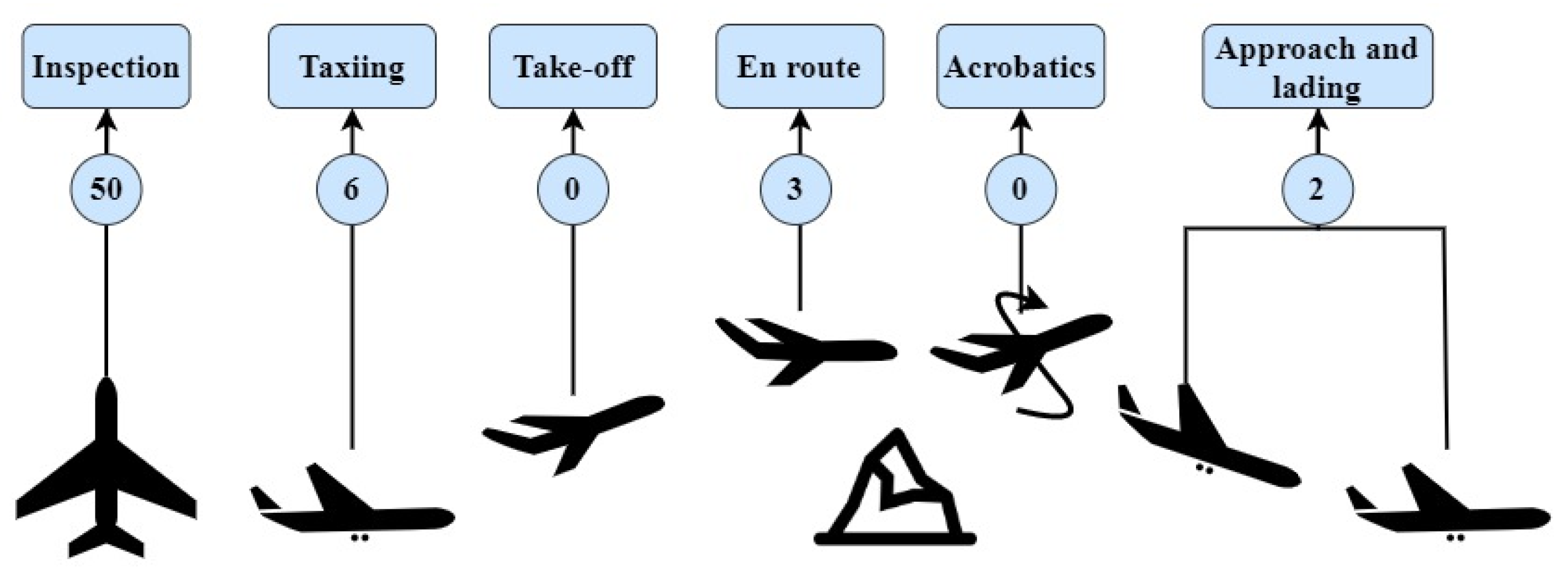
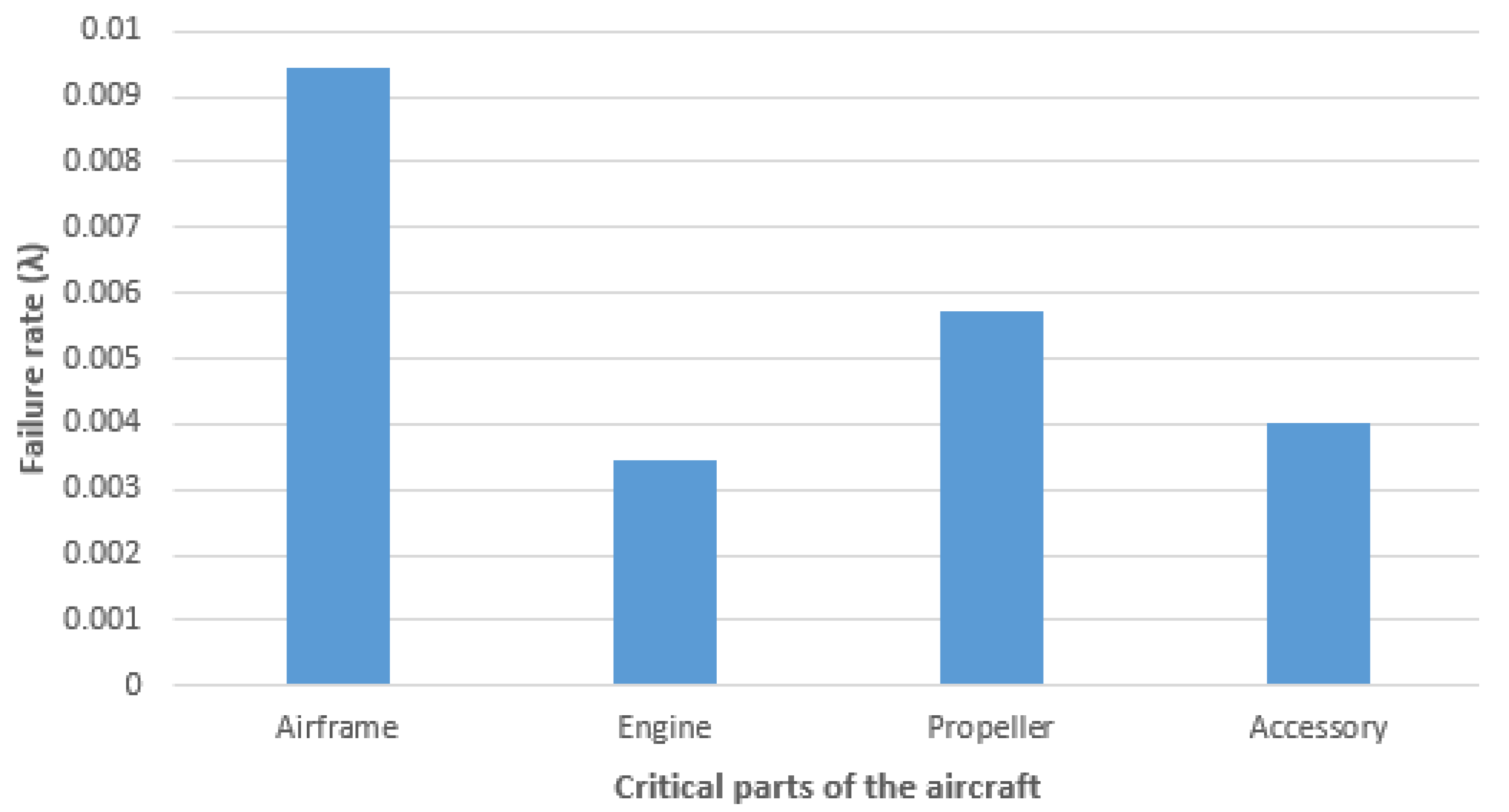
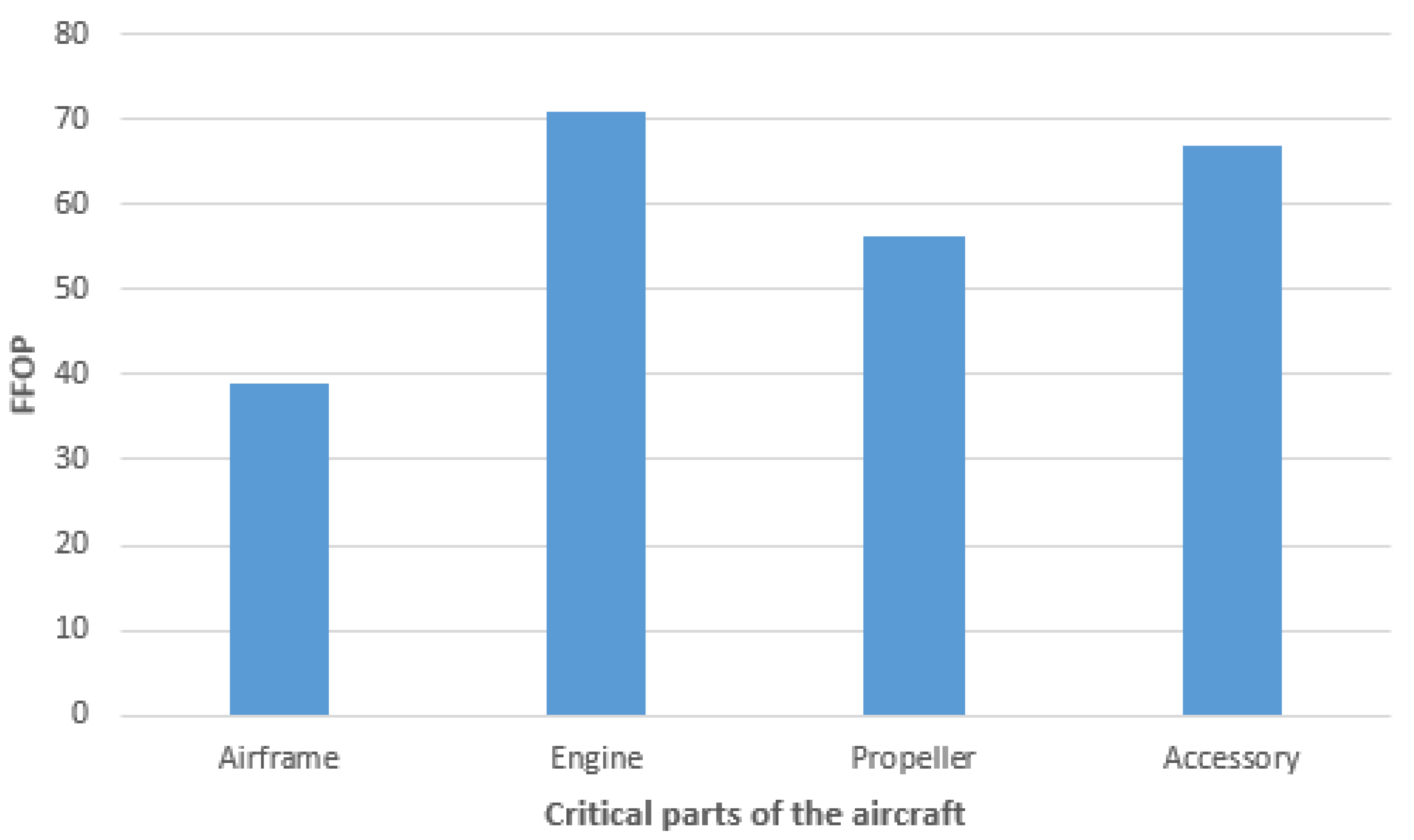
2.3. Failure Indexes

The mean time between failure (MTBF) represents the average time between the malfunction of an asset [26]. In the case study, it expresses the average time for which a failure occurs on one of the aircraft’s components or systems. The MTBF was calculated according to the following formula:
M T B F = 0 t f ( t ) d t 0 f ( t ) d t = 0 t f ( t ) d t = 1 λ .
In reliability and quality control, failure rate functions provide valuable information about the distribution of failure times. An index indicating the ability of a component or body section to perform its task reliably. Time is used in a generic sense, and it can have units such as number of landings, flight hours, number of cycles, etc., depending on the operational profile and the utilization of the system [24,27,28]. In our case, the failure rates “λ(t)” were calculated for individual critical parts according to the following formula, where “f(t)” represents the number of failures and “R(t)” represents the operation time:
λ ( t ) = f ( t ) R ( t )
λ A i r f r a m e = 33 3495 = 0.009442
λ E n g i n e = 12 3495 = 0.003433
λ P r o p e l l e r = 2 3495 = 0.005722
λ A c c e s s o r y = 14 3495 = 0.004005 .
The probability of failure free operation was calculated for individual critical parts; however, in this case, the time period was set to 100 flight hours because after this time, the regular periodic inspection is performed. Values were calculated according to the following formula, where “λ(t)” represents the failure rates of individual critical parts of the aircraft [24]:
( t ) = e 0 λ ( t ) d t
F F O P = ( λ A i r f r a m e 100 ) 100 = 38.89
F F O P = ( λ E n g i n e 100 ) 100 = 70.94
F F O P = ( λ P r o p e l l e r 100 ) 100 = 56.43
F F O P = ( λ A c c e s s o r y 100 ) 100 = 67 .

2.4. Case Study Results

Considering the 3495 flight hours of four Z-142 aircraft and 33 failures that occurred on the airframe, which can be seen in Table 2, it was possible to calculate the MTBF for the airframe over monitored period, which represented 105 h.
M T B F Z- 142   A i r f r a m e = 105   h
The airframe of the aircraft showed the highest failure rate, as can be seen in Figure 3, as it was possible to claim from the total number of failures that were recorded on it. The airframe represents 117% higher intensity of failures than other monitored aircraft’s critical parts. The reason might be that the airframe includes much more elements than other monitored critical parts of the aircraft. The second reason might be its higher operating load during pilots’ training, which affects the components’ service life significantly. Figure 2 shows that the aircraft damage was found both on the outer surfaces and in structural construction.
During the monitored period, the propellers showed the highest probability of failure-free operation, which is related to their lowest failure rate. The lowest FFOP of all critical parts represented the airframe, because of its frequent failures [24], as shown in Figure 4.
The most common cause of failures of the Z-142 aircraft was mainly the operational wear of components, and it accounted for up to 90% of all reported failures. Based on this phenomenon, it could be noticed that the aircraft is used frequently and requires regular maintenance and inspections, especially of critical elements and elements with a limited service life. Only three failures had no identified cause.

3. Results

3.1. The Implementation Suggestions

Based on the results of the failure indexes from the case study, it is desirable to focus on making innovative changes and improvement of maintenance processes, primarily to monitor the technical condition of the airframe. The proposed monitoring solutions define the smart technologies chosen by the authors and further describe the process of the technical condition monitoring, data collection, and subsequent damage assessment. In case of a regular camera, a visual inspection system or VIS consists of an image acquisition subsystem and defect identification subsystem or DIS. The hardware represents the main part of the image acquisition subsystem, which captures the images in real time. The captured images are analyzed and evaluated in the DIS [29]. The use of UAVs as a means of performing non-destructive visual inspections with the aid of a camera is an effective way to detect defects on the surface of an aircraft, especially in the case of large commercial aircraft. The size of the aircraft represents a large area that needs to be examined by professional technical personnel. In order to carry out such inspections safely, technical staff must use support structures, various ladders, platforms, or forms of securing to reach otherwise inaccessible places. The use of a UAV and a camera would reduce the need to use the aforementioned support structures and the need to secure and thus increase the overall safety of technical personnel. In the case of small aircraft, such as those intended for basic pilot flight training, the use of UAVs would not be of much benefit, as the technician can perform a visual inspection of the aircraft without the need for supporting structures or ladders, as the size of the aircraft is significantly smaller. However, the time required for this action could be potentially reduced with the use of the UAV. Moreover, when using a special long-wave infrared camera, which is able to inspect not only external damage, but also structural damage, its installation on the UAV finds its application.

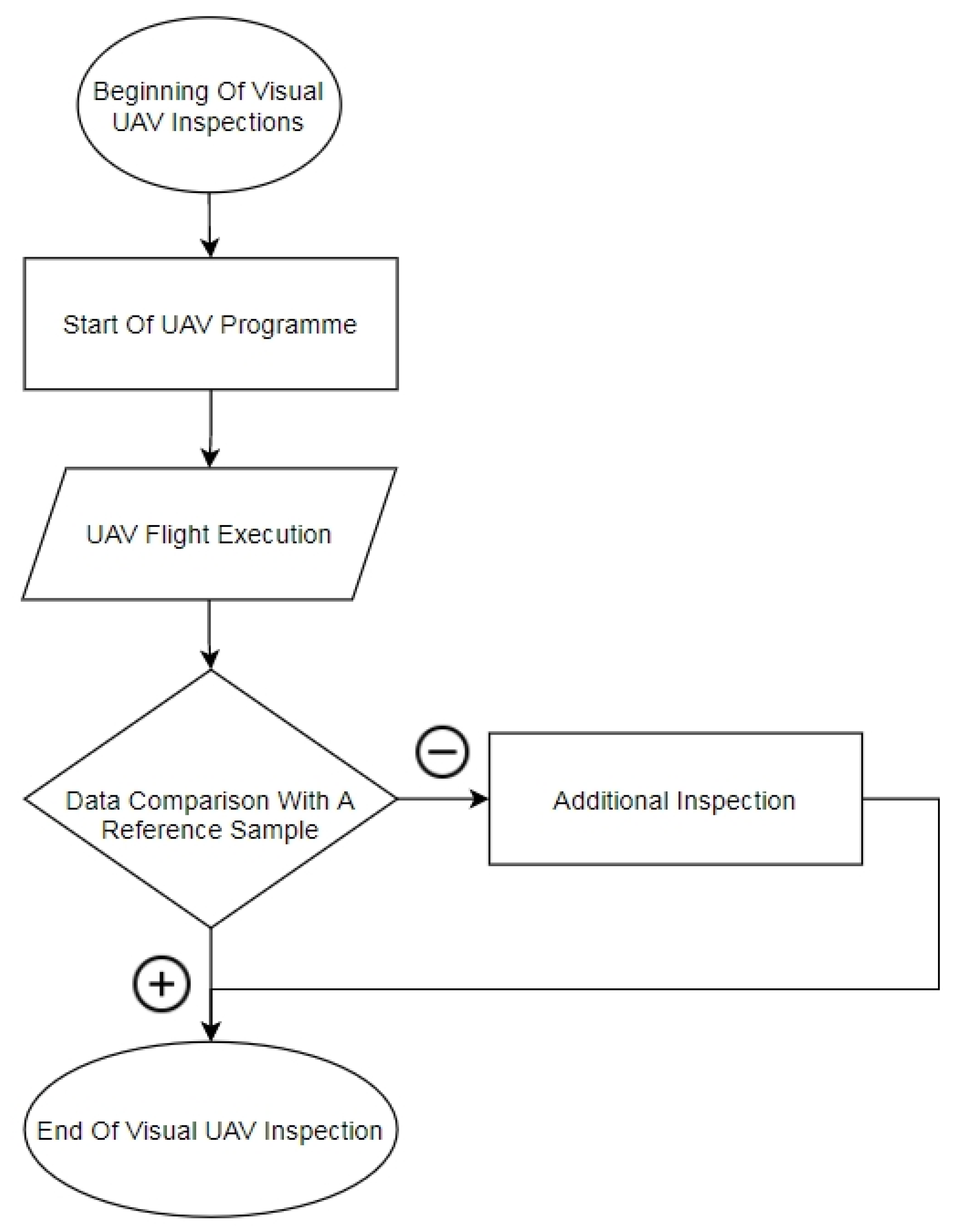
3.2. Visual Inspection Performed by UAV and IR Camera

In general, the recognition model of any object could be expressed with the following procedure steps:
  • Image Acquisition
  • Preprocessing
  • Segmentation
  • Feature Extraction
  • Classification and Recognition
  • Post Processing
An image can be defined as a 2D function f(x,y) where (x,y) is the coordinate in two-dimensional space and f is the intensity of that coordinate. Each coordinate position is called a pixel [30,31]. In case of dynamic imaging, the image could be expressed as a 3D function of three variables f(x,y,z). Since the limited dimensions in the image are assumed, the domain of the image function could be expressed as a Cartesian product from the domain of real numbers that defines the range of the image:
f : ( < x m i n , x m a x > x < y m i n , y m a x > ) H .
The images are generated by the combination of an illumination source and the reflection or absorption of the energy by the elements of the scene being imaged. Illumination may be originated by radar, an infrared energy source, computer generated energy pattern, ultrasound energy source, X-ray energy source, etc. To sense the image, we use a sensor according to the nature of illumination. The process of image sense is called image acquisition [32]. The range of values H of the image function forms a set of values of brightness or colors of the image, which can be expressed by a set of real numbers R or Rn depending on the representation of color information, where n expresses the number of channels, i.e., the color samples used. The computer usually works with a digital image, which is represented by a matrix (grid, raster):
f ( x , y ) = ( f ( 0 , 0 ) f ( 0 , n 1 ) f ( 1 , 0 ) f ( 1 , n 1 ) f ( m 1 , 0 ) f ( m 1 , n 1 ) )
where a right-hand side of this matrix defines the digital image. The element of the matrix represents a pixel. The conversion of an optical image (Real-World Data) into an array of numerical data is essential for the later manipulation with the data in a computer environment; thus, before any video or image processing can commence, an image must be captured by a camera and converted into a manageable entity. This conversion process is the general aim of Image Acquisition [33].
An experiment aimed at the use of UAVs with a regular camera as a form of pre-flight visual inspection of surface damage to a trainer aircraft was carried out at the maintenance center of an approved training organization. According to Novak and Fabra, in order to perform this type of experimental inspection, it is essential to meet the following conditions:
  • Reduce dust particles as much as possible in an inspection environment.
  • Identify the movement of the UAV, the position of personnel with respect to safety (equipped with obstacle anti-collision sensors).
  • Secure the UAV and the aircraft against collisions (propeller protection, definition of the aircraft protection zone according to [30,34]).
Used UAV and Camera Type:
DJI Mavic 2, equipped with an optical sensor FC220, color profile RGB IE61966-2.1, and lens 26.3 mm f/2.2, was chosen for our experiment under UNIZA conditions. The MATLAB MatWorks tool “Deep Learning and Machine Learning for Computer Vision” was used for image processing. It is vital to have clean, sharp, and properly labeled images before the segmentation process, which is the part of the preprocessing algorithm in deep learning. Thanks to the segmentation process, the points of interests such as rivets or screws shown in images could be identified considering their amount, position, and orientation. Thus, after the postprocessing, the analyst (or operator) is aware whether the final number or quantity of said elements coincides with their correct number, in short, whether any screw or rivet is missing or not. This variant of UAV was chosen due to the fact that it represents the dominant type on the market with the support of libraries in MATLAB application [30].
According to previous experience gained from experiments at UNIZA, at first, it is demanding to define the initial environment in order to consider performing a visual inspection with UAV and a long-wave infrared (IR) camera. Secondly, it is necessary to define an appropriate flight path for monitoring desired locations and also determine the time intervals of UAV’s movement with respect to the defined trajectory and gradually end the monitoring process itself. An UAV with the IR camera is represented as a point in three-dimensional space. Before the inspection begins, it is necessary to determine the starting (ending) point of take-off of the unmanned aerial vehicle, its altitude for each reference point within the previous defined trajectory, also the total estimated time of the entire visual inspection. All data scanned by the camera have to be examined as soon as possible. At the end of the operation, the result is comprehensive information on the basis of which the pilot decides whether it is needed to perform a more detailed inspection in case certain irregularities were detected during the visual inspection process [35]. Figure 5 shows a diagram that defines all the steps of the process of implementing a visual inspection using a UAV with a long-wave IR camera attached. The regular camera was able to capture defects that occurred only on the outer surfaces of the aircraft airframe, as shown in Figure 6.
Unlike the conventional camera, whose image consists of pixels, the infrared camera detects and measures the infrared energy of objects without the direct contact [36]. The camera converts that infrared data into an electronic image that shows the apparent surface temperature of the object being measure. With the combination of these two cameras, the inspector has a multi-spectral image of damage. In this case, the Mavic 2 Enterprise series is proposed as an example of a drone that is capable of performing IR visual inspection. This specific portable drone is available in three different variants—Advanced, Dual, and Zoom. The main difference is the quality of their cameras. The Advanced and Dual versions carry two sensors—visual and thermal, while the Zoom variant carries only one visual sensor with zoom capabilities. The weight of these models is about 904 g without accessories and their maximum take-off weight is 1100 g, which is quite light. The Advanced version presents the ideal option for IR visual inspection due to its superior resolution of a visual 48-megapixel sensor, thermal resolution of HD 640 × 512 px at 30 Hz with a spectral band of 8–14 µm, and pixel pitch of 12 µm. The thermal camera provides16× digital zoom functionality. The Operating temperature is from −10 to 40 °C. The operator is able to switch between visual, thermal, or split-view [37].

3.3. Detection of Structural Damages

In general, the temperature of the components heats up before the failure. The component’s temperature is determined according to crisp images without direct contact with the component’s surface. Data could be displayed in real time; also, they could be transferred and subjected to analysis to a digital storage device. Hot spots and excessive heat caused by insufficient insulation are clearly recognized in images before these defects could lead to failure [36]. The thermal infrared technology has been widely used for rescue, surveillance, and automatic target recognition. Tracking based on this technology is not subject to illumination variations; thus, it can track the target in total darkness [38]. The heat signatures of electrical components captured by the FLIR camera are not affected by the surroundings such as the sky or clouds because the camera is capable of their recognition. The ability to recognize these differences is one of the main features of the FLIR camera. The temperatures of the monitored targets can be compared with predefined values set by the user thanks to integrated logic, memory, and data communication. Data are transmitted to a central monitoring station for trend analysis, generating exception reports, and in case the temperatures exceed threshold values or if another abnormal condition is monitored, it can trigger an alarm or send an email message to facility managers in remote offices [36]. According to Ciampa et al. [39], we distinguish two forms of infrared thermography—passive (stationary) and active (non-stationary). Active is one of the precise evaluation techniques of non-destructive testing, especially in the case of the aerospace industry for the inspection of aircraft and helicopters‘ primary and secondary structures, engine parts, composite materials, and subsystems. Passive infrared thermography is used to inspect a variety of materials, including aluminum and composites, which make up 50% of aircraft constructions. The most common aircraft failures are cracks, fatigue cracks, barely visible impact damage (BVDI), delaminations, disbonding matrix/fiber cracks, voids, water ingress, and core crushing. The passive form is usually used for materials that have a different temperature from the environment temperature in which they are operated; thus, this temperature can be captured by an IR camera [39]. Montesano et al. [40] claims that passive thermography can be used for the detection of water ingress just after aircraft landing when the temperature difference between the aircraft and water is significant. According to InfraTec [41], measurement tasks of the aerospace industry often require infrared cameras with very high thermal resolutions of 20 mk and/or a high frame rate of 100 Hz and more. The thermal cameras with such high sensitivity are also much bigger and heavier. Both weight and size are the major limitations that affect the usability of the camera for installation on UAV. The Mavic 2 Enterprise Advanced features a FLIR longwave infrared camera and a visual camera, providing both infrared and visible light imaging simultaneously. The FLIR camera provides high-sensitivity (<50 mK). Cameras with 50 mK are about 4 times as sensitive as a camera with 200 mK. The more sensitive cameras provide a wider temperature difference, resulting in more colors on the thermal display.

3.4. Time-Saving Prognosis

As was previously mentioned, airframe inspections are performed every 100 flight hours or once a year. It is the longest inspection in terms of time. Based on the sum of flight hours of the four Zlin Z-142 aircraft during the whole time period of six years, it can be concluded that at least 35 routine inspections of the airframe were performed. In case of inspection, not only monitoring capabilities are important but also the time. Regular airframe checks are quite time-consuming actions. Based on our findings, it takes the mechanic roughly 30 min on average to perform such a task. However, this time is not the overall time of inspection, because actions done by a mechanic have to be additionally verified by a certified mechanic. This process also takes from 20 to 30 min and can not be rushed. According to previous experiments done in UNIZA, Novak claims that the time required to carry out the visual airframe inspection of PA34-220T SENECA, which is a twin-engine light aircraft, is around 5 min. These times may vary, depending on either the UAV is flying manually by the operator or the UAV flies according to predefined flight pattern [30]. Table 4 shows the times required for individual processes for both UAV and regular inspections. It possible to see that the time difference in case of UAV inspection is 60 min shorter.

3.5. Structural Repair and Airframe Condition Monitoring by Using RFID and CMB

Automated aircraft inspection basically aims at automating the visual inspection process normally carried out by aircraft engineers. It aims at detecting defects that are visible on the aircraft skin, which are usually structural defects. These defects can include dents, lightning strike damage, paint defects, fasteners defects, corrosion, and cracks [42].
The RFID tag looks similar to a bar code but offers more beneficial features. The main benefits are data storage and enhanced data collection, the ability to read without a direct view of the RFID label, a dynamic read/write capability, simultaneous reading and identification of multiple tags, and the ability to withstand a harsh environment.

3.5.1. Contact Memory Button (CMB)

One of the smart ways of storing data related to specific components represent the contact memory button or CMB, which was widely used in military application, but now it may find its application in the civil sector as well. This device is a form of automated identification technologies (AIT) capable of storing data in various forms and formats such as a small USB flash disk, including images, PDF copies of repair orders, and re-inspection requests. The capacity of these devices is up to 4 gigabytes of data. These data could be represented as the part number or serial number, date of its manufacture, or its maintenance history. The data saved on RFID tags can be read or be updated wirelessly by a hand scanner [43]. By integrating RFID, we can improve airframe maintenance by allowing mechanics to use a CMB (Contact Memory Button) tag, which records all relevant data on previous and current repairs made to the airframe design. This solution allows placement and easy display in case of subsequent maintenance. Such use has advantages especially when used on composite structures and allows detecting hidden repairs—repairs that were not recorded or uploaded to the contact memory button (CMB). However, this device is not an ideal choice in terms of increasing the effectiveness of visual inspection performed by UAV, which is mainly due to the reason that these buttons could not be read wirelessly from distance, as they work only with the USB interface. Therefore, this option is possible only when the visual check is performed by a mechanic.

3.5.2. RAIN RFID Tags

The more suitable option is to apply RAID RFID tags, which are an advanced version of the basic RFID tags working with the ultra high frequency (UHF) band, which are readable from the range of 12 m. RAIN RFID systems comply with the UHF Gen2 standard and use the 860 to 960 MHz band (EU).
UHF RFID has a faster data transfer rate than lower frequency (LF) or high frequency (HF). UHF RFID is the most sensitive to interference, but many UHF product manufacturers have found ways of designing tags, antennas, and readers to keep performance high even in difficult environments [44]. Such tags could be placed anywhere on the desired component without the need of invasion to its material. It represents a non-invasive method and works as a labeling tool. The limitation is to place them on or beneath the composites, as the signal could only penetrate through composite materials. In our conditions, the application could be on load-bearing structures, in place of conductive connections or laminated parts of the aircraft. These tags can identify also the nut or rivet release if the tag is placed between the airframe surface and the nut. If the conductive connection between the surface and the nut is cut off, the loosening of the nut is indicated. The connection of infrared camera and RFID provides the clear picture of aircraft power line state. As it was mentioned previously, overheating may indicate the possible short circuit caused by corrosion on the electrical contacts or insufficient isolation of connections.

3.5.3. RFID as a Labeling Tool

Our proposed solution is to attach the RAIN RFID tags to a critical part of the aircraft—on particular components, for example, the flap. The tag could be stuck on the outer surface of the flap. This tag would identify the component as a particular item with all its specifications (number of rivets), which would be monitored by the camera. Previously, the bar codes or numbered marks were used; however, they could not be read by a camera if they were on the inner surface. Therefore, we suggest using RFID tags, which would be read by a camera attached on a UAV; then, the particular component (flap) would be labeled with the image. Based on the image labeling process, the identification, denoising, and classification process follows. In the last step, after the postprocessing, we know if some element is missing.

4. Discussion

The advantage of the proposed implementation of a long-wave infrared camera is the ability to monitor the technical condition of the aircraft airframe not only by inspecting the surface but also the structure of the airframe composite materials. In this way, it is not only possible to monitor the airframe but also damage to the propeller and engine components. The attachment of an IR camera to the UAV allows autonomous control based on a predefined flight pattern. In addition, if necessary, the UAV can be operated manually and the critical point inspected repeatedly if necessary. Moreover, the benefits include the option to choose a thermal camera depending on the monitoring goal. A suitable variant of the IR camera can monitor the electrical elements of the aircraft and determine the temperatures of the electrical circuits based on the radiated thermal radiation. Therefore, it would be possible to determine whether there is overheating at any point and thus avoid failure. The question is whether such a camera would be able to monitor temperature changes of smaller electrical elements. The aircraft accessories such as aircraft instruments and avionics operate at lower voltages; thus, it is questionable whether the proposed variant would be able to determine temperature differences and accurately determine any failure.
The crucial part of the monitoring is the measurement conditions. The power line must be overload permanently while inspecting with an emphasis on not exceeding the limits of fuses. This process must be carried out in order to achieve maximum values where the damage is not presented yet. After the operator is familiar with the threshold temperature values, it is possible to detect failures. Here comes to mind the question of whether these overloading actions may not cause the failure itself.
Other risks include the unsolicited return to a home feature, which turns automatically when the drone battery reaches low values. Such a feature could endanger the aircraft itself if it is not done correctly. A suggested type of drone could fly in the windless conditions for about 31 min, depending on how many of its accessories are turned on, e.g., speaker, spotlight, beacon. These additional devices affect the battery, thus also the operation time.
With the help of RFID technology and the installation of CMB equipment in critical places in composite structures, it provides an overview of previous maintenance performed. Regardless of this benefit, in our conditions, the use of CMB does not find its application; rather, we focused on the RAIN RFID tags, which could be read wirelessly, even from the drone.

5. Conclusions

In order to increase the effectiveness of monitoring the technical condition of a trainer aircraft airframe, two variants of implementations were proposed. The use of an unmanned aerial vehicle (UAV) to which a long-wave infrared camera would be attached would allow visual inspections of both surface and structural damage. In addition to the aircraft airframe composite structure, this solution also allows monitoring the technical condition of the propeller and engine components. By implementing this variant, it is possible to save time performing visual as well as structural inspections; in addition, when choosing the right variant of the IR camera, it could be possible to monitor the electronic elements of the aircraft. Ultimately, the proposed implementations can achieve reliable monitoring of the technical condition of the airframe, engine, propeller, and electronic elements of the aircraft, increase safety, and reduce the workload of technical personnel, reduce downtime, and ensure the reliable maintenance of maintenance records.
RFID technology, specifically UHF RFID, is an excellent supporting tool for visual inspection by drone. In addition to monitoring of structural electrical failures, with the use of UHF, it is possible to identify any rivet or screw release of components equipped with it.
New ways of condition monitoring could increase the effectiveness of the trainer aircraft maintenance as well as save time, costs, and manpower. For the small MRO, these suggestions present new possible ways of adapting to predictive maintenance strategy and replace time-consuming processes of preventive maintenance strategies.
The future direction of our research would be experimental application of RFID tags for the detailed inspection of various rivet and nuts release monitoring. Testing their conductivity on various materials including metal, wood, and composite materials. The limitation of this technology include the read range and possible installation of an antenna to a UAV.

Author Contributions

M.H., M.B., and A.N. developed the conceptualization and investigation of this work. A.N., B.K., and B.B. conducted the experimental part—visual inspection of the aircraft airframe by unmanned aerial vehicle with camera at UNIZA. M.H. and M.B. were responsible for the calculation and validation of failure indexes. A.N. took part in verification of the image acquisition. All authors participated in the analysis of the results. All authors have read and agreed to the published version of the manuscript.

Funding

This research received no external funding.

Institutional Review Board Statement

Not applicable.

Informed Consent Statement

Not applicable.

Data Availability Statement

Not applicable.

Acknowledgments

This publication was realized with support of the Operational Programme Integrated Infrastructure in frame of the project: Intelligent systems for UAV real-time operation and data processing, code ITMS2014+: 313011V422 and co-financed by the European Regional Development Found.

Conflicts of Interest

The authors declare no conflict of interest.

Abbreviations

The following abbreviations are used in this manuscript:
A/CAircraft
BVIDBarely visible impact damage
CAMOContinuing Airworthiness Management Organization
CMBContact memory button
DISDefect identification subsystem
FAAFederal Aviation Administration
FFOPProbability of trouble or failure free operation
FPIFluorescent penetrant inspection
HFHigh frequency
IFRInstrumental Flight Rules
IRInfrared Radiation
LFLower frequency
MROMaintenance and Repair Organization
MTBFMean time between failure
NDTNon-destructive testing
RAINRadio frequency identification
RFIDRadio frequency identification
UHFUltra high frequency
UAVUnmanned Aerial Vehicle
UNIZAUniversity of Žilina
VFRVisual Flight Rules
VISVisual inspection system
WLIWhite light interferometry

References

  1. Valdés, R.A.; Comendador, V.F.G.; Sanz, A.R.; Castán, J.P. Aviation 4.0: More Safety through Automation and Digitization. Aircr. Technol. 2018, 7, 225–236. [Google Scholar] [CrossRef] [Green Version]
  2. Chen, T.; Tsai, H.-R. Ubiquitous manufacturing: Current practices, challenges, and opportunities. Robot. Comput. Manuf. 2017, 45, 126–132. [Google Scholar] [CrossRef]
  3. Keivanpour, S.; Kadi, D.A. The Effect of “Internet of Things” on Aircraft Spare Parts Inventory Management. IFAC-PapersOnLine 2019, 52, 2343–2347. [Google Scholar] [CrossRef]
  4. Federal Aviation Administration. Aviation Maintenance Technician Handbook–General, FAA-H-8083-30A. 2018. Available online: https://www.faa.gov/regulations_policies/handbooks_manuals/aircraft/media/amt_general_handbook.pdf (accessed on 16 March 2021).
  5. Nowlan, F.S.; Heap, H.F. Reliability-Centered Maintenance; Maintenance Quality Systems LLC: San Francisco, CA, USA, 1978. [Google Scholar]
  6. Keivanpour, S.; Kadi, D.A. A sustainable approach to Aircraft Engine Maintenance. IFAC-PapersOnLine 2015, 48, 977–982. [Google Scholar] [CrossRef]
  7. Eschen, H.; Kötter, T.; Rodeck, R.; Harnisch, M.; Schüppstuhl, T. Augmented and Virtual Reality for Inspection and Maintenance Processes in the Aviation Industry. Procedia Manuf. 2018, 19, 156–163. [Google Scholar] [CrossRef]
  8. Bacim, F.; Ragan, E.; Scerbo, S.; Polys, N.F.; Setareh, M.; Jones, B.D. The effects of display fidelity, visual complexity, and task scope on spatial understanding of 3d graphs. Proc. Graph. Interf. 2013, 2013, 25–32. [Google Scholar]
  9. Bischoff, R.; Kazi, A. Perspectives on augmented reality based human-robot interaction with industrial robots. In Proceedings of the 2004 IEEE/RSJ International Conference on Intelligent Robots and Systems (IROS) (IEEE Cat. No.04CH37566), Sendai, Japan, 28 September–2 October 2004; Institute of Electrical and Electronics Engineers (IEEE): Piscataway, NJ, USA, 2005; Volume 4, pp. 3226–3231. [Google Scholar]
  10. Chong, J.; Ong, S.; Nee, A.; Youcef-Youmi, K. Robot programming using augmented reality: An interactive method for planning collision-free paths. Robot. Comput. Manuf. 2009, 25, 689–701. [Google Scholar] [CrossRef]
  11. Goldman Sachs. “Drones: Reporting for work”, Goldman Sachs Research. 2016. Available online: www.goldmansachs.com/insights/technology-driving-innovation/drones/ (accessed on 6 February 2019).
  12. Mazur, M.; Wiśniewski, A. “Clarity from above”, PwC Polska Sp. z o.o. 2016. Available online: https://www.pwc.com/hu/hu/kiadvanyok/assets/pdf/clarity-from-above-leveraging-drone-technologies-to-secure-utilities-systems-pwc.pdf (accessed on 22 August 2018).
  13. Kurdel, P.; Sedláčková, A.N.; Labun, J. UAV flight safety close to the mountain massif. Transp. Res. Procedia 2019, 43, 319–327. [Google Scholar] [CrossRef]
  14. Škultéty, F.; Badánik, B.; Bartoš, M.; Kandera, B. Design of Controllable Unmanned Rescue Parachute Wing. Transp. Res. Procedia 2018, 35, 220–229. [Google Scholar] [CrossRef]
  15. Dale, J.; Burnside, N.; Hill-Butler, C.; Berg, M.; Strong, C.; Burgess, H. The Use of Unmanned Aerial Vehicles to Determine Differences in Vegetation Cover: A Tool for Monitoring Coastal Wetland Restoration Schemes. Remote Sens. 2020, 12, 4022. [Google Scholar] [CrossRef]
  16. Li, B.; Gan, Z.; Chen, D.; Aleksandrovich, D.S. UAV Maneuvering Target Tracking in Uncertain Environments Based on Deep Reinforcement Learning and Meta-Learning. Remote Sens. 2020, 12, 3789. [Google Scholar] [CrossRef]
  17. Sedlackova, A.N.; Kurdel, P.; Mrekaj, B. Synthesis criterion of ergatic base complex with focus on its reliability. In Proceedings of the 2017 IEEE 14th International Scientific Conference on Informatics, Poprad, Slovakia, 14–16 November 2017; Institute of Electrical and Electronics Engineers (IEEE): Piscataway, NJ, USA, 2017; pp. 318–321. [Google Scholar]
  18. Sedláčková, A.N.; Kurdel, P.; Labun, J. Simulation of Unmanned Aircraft Vehicle Flight Precision. Transp. Res. Proced. 2020, 44, 313–320. [Google Scholar] [CrossRef]
  19. Ceruti, A.; Marzocca, P.; Liverani, A.; Bil, C. Maintenance in aeronautics in an Industry 4.0 context: The role of Augmented Reality and Additive Manufacturing. J. Comput. Des. Eng. 2019, 6, 516–526. [Google Scholar] [CrossRef]
  20. Domaschke, T.; Schueppstuhl, T.; Otto, M. Robot Guided White Light Interferometry for Crack Inspection on Airplane Engine Components. ISR/Robotik 2014. In Proceedings of the 41st International Symposium on Robotics, Munich, Germany, 2–3 June 2014; pp. 1–7. [Google Scholar]
  21. Shin, H.; Abbas, S.H.; Thanh Ch, T. A Proof-of-concept of Smart Hangar for Composite Aircraft. In Proceedings of the International Conference on Composite Materials, Copenhagen, Denmark, 19–24 July 2015. [Google Scholar] [CrossRef]
  22. Ciampoli, L.B.; Gagliardi, V.; Ferrante, C.; Calvi, A.; D’Amico, F.; Tosti, F. Displacement Monitoring in Airport Runways by Persistent Scatterers SAR Interferometry. Remote Sens. 2020, 12, 3564. [Google Scholar] [CrossRef]
  23. Holl, J. Hangar of the future Excelling in MRO. 6 December 2016. Airbus S.A.S. Available online: https://www.airbus.com/newsroom/news/en/2016/12/Hangar-of-the-future.html (accessed on 10 December 2020).
  24. Hrúz, M.; Pecho, P.; Mariášová, T.; Bugaj, M. Innovative changes in maintenance strategies of ATO’s aircraft based on their operational status. Transp. Res. Procedia 2020, 51, 261–270. [Google Scholar] [CrossRef]
  25. Janovec, M.; Smetana, M.; Bugaj, M. Eddy Current Array Inspection of Zlin 142 Fuselage Riveted Joints. Transp. Res. Procedia 2019, 40, 279–286. [Google Scholar] [CrossRef]
  26. Smith, R.; Mobley, R.K. Chapter 17: MTBF User Guide: Measuring Mean Time between Failures. In Rules of Thumb for Maintenance and Reliability Engineers; Butterworth-Heinemann Elsevier Ltd.: Oxford, UK, 2008; p. 336. ISBN 978-0-7506-7862-9. [Google Scholar]
  27. Bugaj, M. Failure Analysis—Basic Step of Applying Reliability Centered Maintenance in General Aviation. Transp. Probl. Int. Sci. J. 2012, 7, 77–86. [Google Scholar]
  28. Wiksten, J.; Johansson, M. Maintenance and Reliability with Focus on Aircraft Maintenance and Spares Provisioning. Ph.D. Thesis, Luleå University of Technology, Luleå, Sweden, 2006. [Google Scholar]
  29. Li, Q.Y.; Zhong, Z.D.; Liu, M.; Fang, W.W. Chapter 14: Smart Railway Based on the Internet of Things. In Intelligent Data-Centric Systems Big Data Analytics for Sensor-Network Collected Intelligence; Academic Press: London, UK, 2017; pp. 280–297. ISBN 9780128093931. [Google Scholar]
  30. Novák, A.; Sedláčková, A.N.; Bugaj, M.; Kandera, B.; Lusiak, T. Use of Unmanned Aerial Vehicles in Aircraft Maintenance. Transp. Res. Procedia 2020, 51, 160–170. [Google Scholar] [CrossRef]
  31. Yadav, A.; Yadav, P. Digital Image Processing, 1st ed.; Laxmi Publications: Boston, MA, USA, 2009; p. 234. ISBN 9788131805244. [Google Scholar]
  32. Mishra, V.K.; Kumar, S.; Shukla, N. Image Acquisition and Techniques to Perform Image Acquisition. SAMRIDDHI J. Phys. Sci. Eng. Technol. 2017, 9, 21–24. [Google Scholar] [CrossRef]
  33. Sugimura, D.; Mikami, T.; Yamashita, H.; Hamamoto, T. Enhancing Color Images of Extremely Low Light Scenes Based on RGB/NIR Images Acquisition with Different Exposure Times. IEEE Trans. Image Process. 2015, 24, 3586–3597. [Google Scholar] [CrossRef]
  34. Fabra, F.; Zamora, W.; Sangüesa, J.; Calafate, C.T.; Cano, J.-C.; Manzoni, P. A Distributed Approach for Collision Avoidance between Multirotor UAVs Following Planned Missions. Sensors 2019, 19, 2404. [Google Scholar] [CrossRef] [PubMed] [Green Version]
  35. Bugaj, M.; Novak, A.; Stelmach, A.; Lusiak, T. Unmanned Aerial Vehicles and Their Use for Aircraft Inspection. In Proceedings of the 2020 New Trends in Civil Aviation (NTCA), Prague, Czech Republic, 23–24 November 2020; IEEE: Piscataway, NJ, USA, 2020; pp. 45–50. [Google Scholar]
  36. FLIR Systems, Inc. 2020. Available online: https://www.flir.eu/instruments/science/ndt-materials-testing (accessed on 20 November 2020).
  37. DJI. Mavic 2 Enterprise Advanced. Available online: https://enterprise.dji.com (accessed on 20 February 2021).
  38. Wu, S.; Zhang, K.; Li, S.; Yan, J. Learning to Track Aircraft in Infrared Imagery. Remote Sens. 2020, 12, 3995. [Google Scholar] [CrossRef]
  39. Ciampa, F.; Mahmoodi, P.; Pinto, F.; Meo, M. Recent Advances in Active Infrared Thermography for Non-Destructive Testing of Aerospace Components. Sensors 2018, 18, 609. [Google Scholar] [CrossRef] [PubMed] [Green Version]
  40. Montesano, J.; Bougherara, H.; Fawaz, Z. Application of infrared thermography for the characterization of damage in braided carbon fiber reinforced polymer matrix composites. Compos. Part B Eng. 2014, 60, 137–143. [Google Scholar] [CrossRef]
  41. InfraTec. Thermography in Aerospace Industry. Available online: https://www.infratec.eu/thermography/industries-applications/aerospace-industry/ (accessed on 20 February 2021).
  42. Doğru, A.; Bouarfa, S.; Arizar, R.; Aydoğan, R. Using Convolutional Neural Networks to Automate Aircraft Maintenance Visual Inspection. Aerospace 2020, 7, 171. [Google Scholar] [CrossRef]
  43. The Boeing Company, RFID Optimizes Maintenance Efficiency. Aeromagazine, a Quarterly Publication, 2012, QTR 01, 12. Available online: https://www.boeing.com/commercial/aeromagazine/articles/2012_q1/pdfs/AERO_2012q1_article2.pdf (accessed on 8 April 2021).
  44. Impinj (NASDAQ: PI) Connectivity Platform: A Foundation for IoT Solutions. Types of RFID Systems. Available online: https://www.impinj.com/products/technology/how-can-rfid-systems-be-categorized (accessed on 19 March 2021).
Figure 1. Phases of flight or operation in which failures have been detected, Source: [24].
Applsci 11 03737 g001
Figure 2. Scheme of individual aircraft failures, location, and consequences of failures, Source: [24].
Applsci 11 03737 g002
Figure 3. Failure intensity of individual critical parts of Z-142, Source: [24].
Applsci 11 03737 g003
Figure 4. The probability of failure-free operation of individual critical parts of Z-142, Source: [24].
Applsci 11 03737 g004
Figure 5. Flowchart of visual inspection using UAV and IR camera. Source: Authors.
Applsci 11 03737 g005
Figure 6. In-flight (vision) screen of the operator performing the PA34-220T SENECA V airframe inspection, Source: [30].
Applsci 11 03737 g006
Table 1. The overview of all trainer aircraft operated by education and training center of Žilina Airport, Source: [24].
Type of A/CQuantity of A/CAge of A/C
Z-142436
Z-42338
Z-43236
PA-3426;29
PA-28231;37
Table 2. The annually report of flight intensity of all four Z-142 aircraft, Source: [24].
YearFlight HoursAmount of Starts
2012659 h 0 min2022
2013533 h 0 min1463
2014304 h 0 min770
2015584 h 20 min1653
2016653 h 15 min1798
2017762 h 55 min2597
Sum3495 h10,303
Table 3. Annual failures occurrence on all four Z-142 aircraft, Source: [24].
YearAirframeEnginePropellerAccessorySum
2012620412
201380019
201442006
201553008
2016522514
2017530412
Sum331221461
Table 4. Time comparison between inspections done by UAV and mechanic, Source: Authors.
Visual
Inspection
Evaluation ProcessRelease Airworthiness Review Certificate
Post
Processing
Verification Process
Drone Inspection5 min30 min30 min120 min
Mechanic Inspection30 min060 min180 min
Publisher’s Note: MDPI stays neutral with regard to jurisdictional claims in published maps and institutional affiliations.

