
Generating Airborne Ultrasonic Amplitude Patterns Using an Open Hardware Phased Array


Abstract
:1. Introduction
2. Related Work
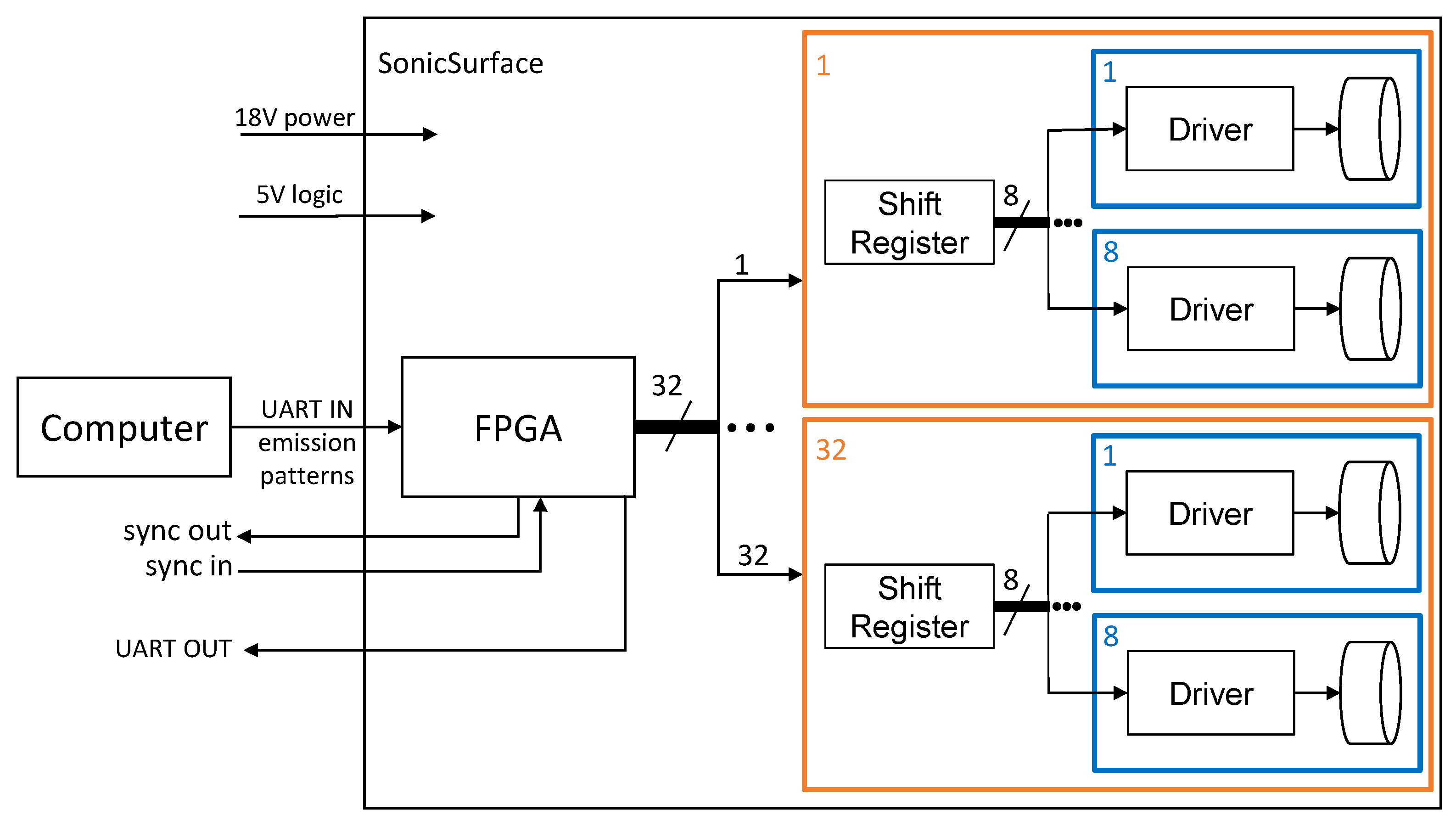
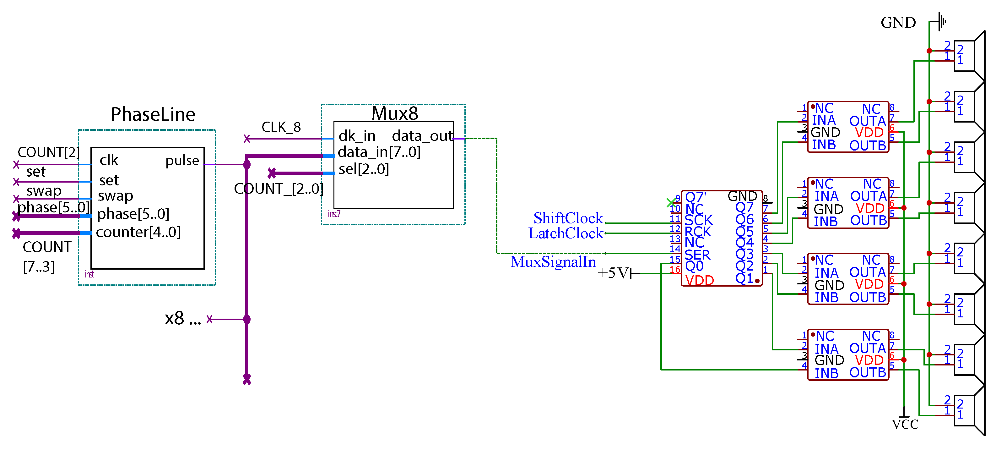
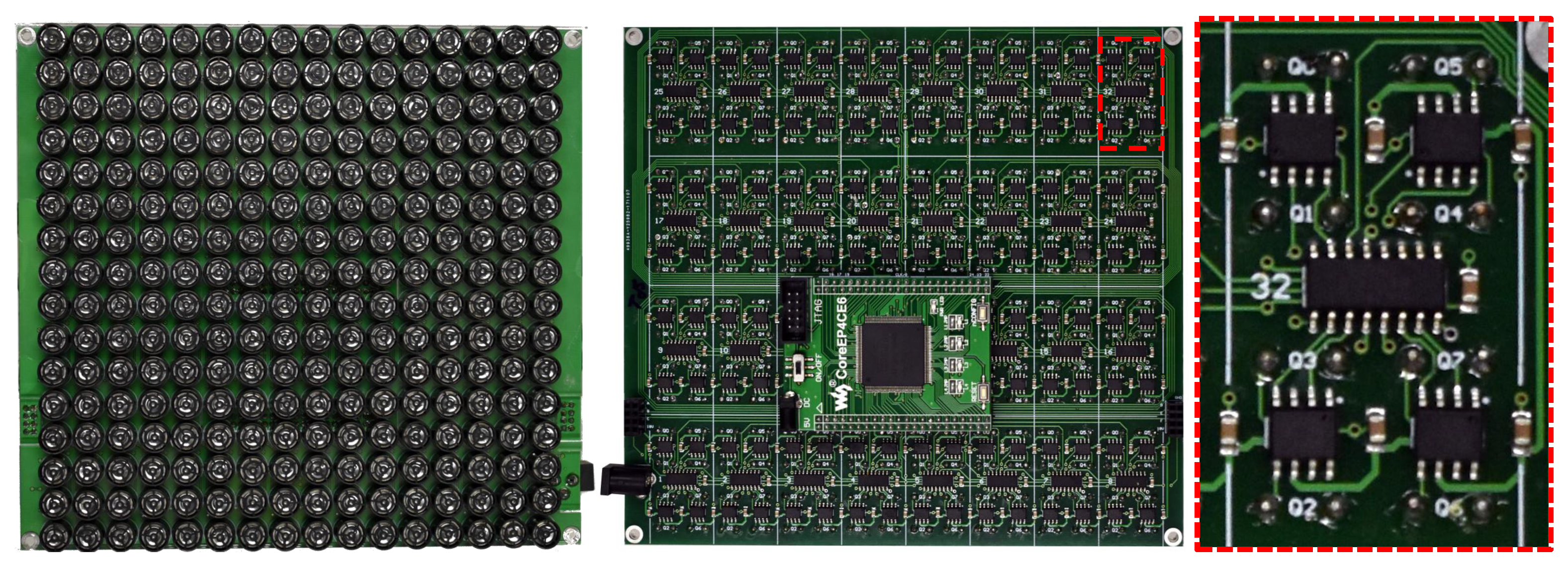
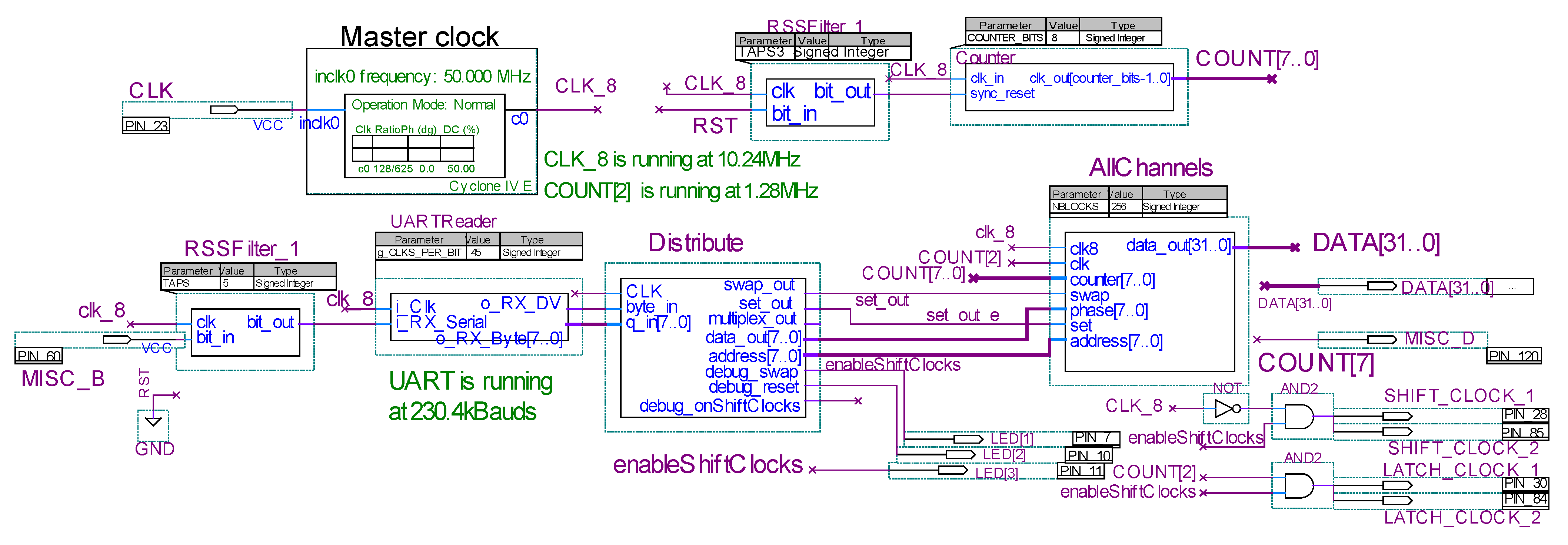
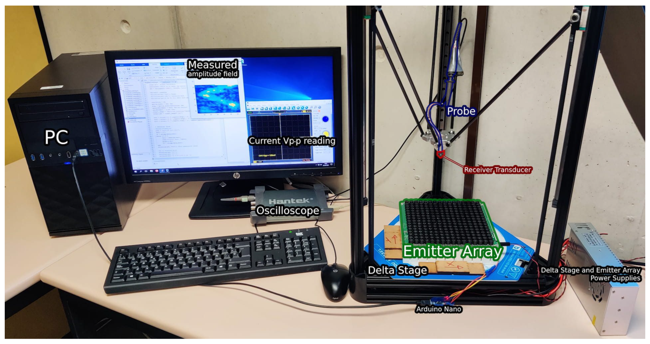
3. Hardware Design
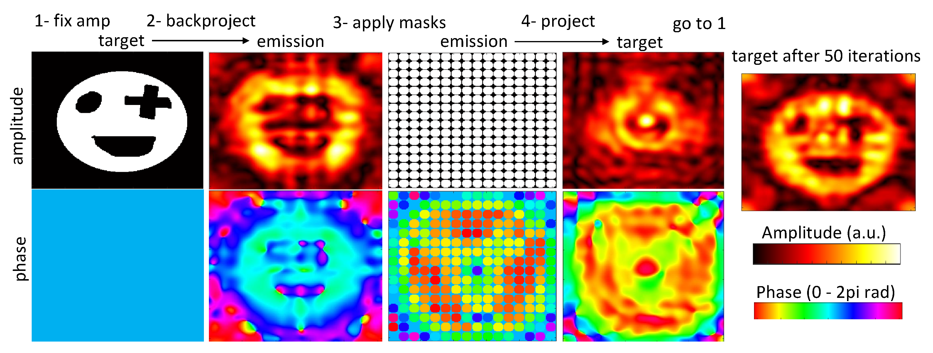
4. Algorithm
5. Results
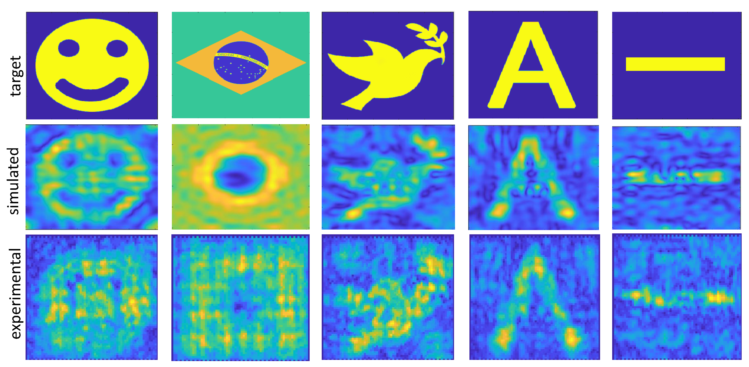
5.1. Comparison between Simulations and Experiments
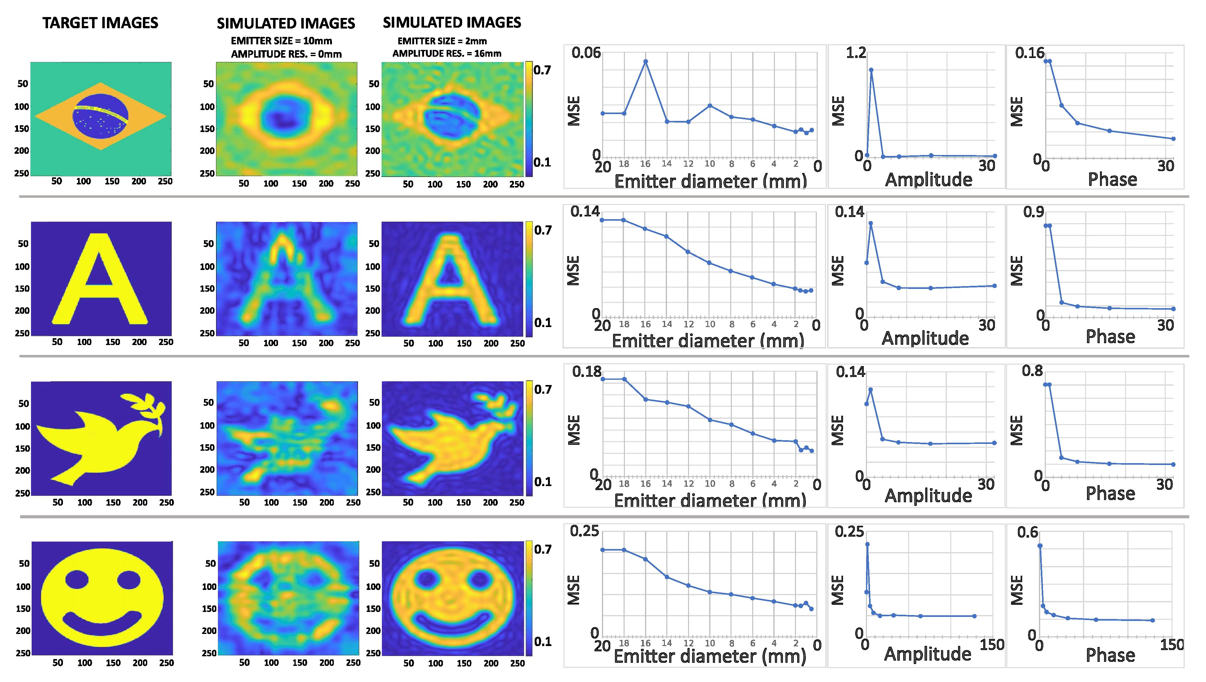
5.2. Effect of Phase, Amplitude, and Spatial Resolution
6. Conclusions
Author Contributions
Funding
Data Availability Statement
Acknowledgments
Conflicts of Interest
Abbreviations
| FPGA | A field-programmable gate array |
| PLL | Phase-locked loop |
| HCI | Human-Computer Interaction |
| HIFU | High-intensity focused ultrasound |
| 3D | Three-dimensional |
| Hz | Hertz is the derived unit of frequency in the International System of Units (SI) |
| kHz | Kilohertz |
| MHz | Megahertz |
| PCB | Printed circuit board |
| UART | Universal asynchronous receiver-transmitter |
| PLL | Phased locked loop |
| PWM | Pulse width modulation |
| I/O | Input and Output |
| GPIOs | A general-purpose inputs/outputs |
| V | Voltage |
| MOSFET | Metal–oxide–semiconductor field-effect transistor |
| SMD | Surface mounted device |
| TH | Through-hole |
| MSE | Mean square error |
| MT | Mounted |
| Vp-p | Peak-to-peak voltage |
| a.u. | Arbitrary unity |
| mm | Millimetre |
| cm | Centimetre |
| rad | Radian |
| uF | Microfarad |
References
- Macovski, A. Ultrasonic imaging using arrays. Proc. IEEE 1979, 67, 484–495. [Google Scholar] [CrossRef]
- Drinkwater, B.W.; Wilcox, P.D. Ultrasonic arrays for non-destructive evaluation: A review. NDT E Int. 2006, 39, 525–541. [Google Scholar] [CrossRef]
- Movahed, A.; Waschkies, T.; Rabe, U. Air Ultrasonic Signal Localization with a Beamforming Microphone Array. Adv. Acoust. Vib. 2019, 2019, 7691645. [Google Scholar] [CrossRef]
- Bailey, M.R.; Khokhlova, V.A.; Sapozhnikov, O.A.; Kargl, S.G.; Crum, L.A. Physical mechanisms of the therapeutic effect of ultrasound (a review). Acoust. Phys. 2003, 49, 369–388. [Google Scholar] [CrossRef]
- Hoshi, T.; Takahashi, M.; Iwamoto, T.; Shinoda, H. Noncontact tactile display based on radiation pressure of airborne ultrasound. IEEE Trans. Haptics 2010, 3, 155–165. [Google Scholar] [CrossRef] [PubMed]
- Carter, T.; Seah, S.A.; Long, B.; Drinkwater, B.; Subramanian, S. UltraHaptics: Multi-point mid-air haptic feedback for touch surfaces. In Proceedings of the UIST 2013—26th Annual ACM Symposium on User Interface Software and Technology, St. Andrews, UK, 8–11 October 2013; pp. 505–514. [Google Scholar] [CrossRef] [Green Version]
- Frier, W.; Pittera, D.; Ablart, D.; Obrist, M.; Subramanian, S. Sampling Strategy for Ultrasonic Mid-Air Haptics. In CHI ’19: Proceedings of the 2019 CHI Conference on Human Factors in Computing Systems; Association for Computing Machinery: New York, NY, USA, 2019; pp. 1–11. [Google Scholar] [CrossRef] [Green Version]
- Fushimi, T.; Marzo, A.; Drinkwater, B.W.; Hill, T.L. Acoustophoretic volumetric displays using a fast-moving levitated particle. Appl. Phys. Lett. 2019, 115, 064101. [Google Scholar] [CrossRef]
- Hirayama, R.; Martinez Plasencia, D.; Masuda, N.; Subramanian, S. A volumetric display for visual, tactile and audio presentation using acoustic trapping. Nature 2019, 575, 320–323. [Google Scholar] [CrossRef] [PubMed]
- Ochiai, Y.; Hoshi, T.; Suzuki, I. Holographic Whisper: Rendering Audible Sound Spots in Three-Dimensional Space by Focusing Ultrasonic Waves. In Proceedings of the 2017 CHI Conference on Human Factors in Computing Systems; Association for Computing Machinery: New York, NY, USA, 2017; pp. 4314–4325. [Google Scholar]
- Bourland, A.C.; Gorman, P.; McIntosh, J.; Marzo, A. Project telepathy. Interactions 2018, 25, 16–17. [Google Scholar] [CrossRef]
- Hoshi, T.; Ochiai, Y.; Rekimoto, J. Three-dimensional noncontact manipulation by opposite ultrasonic phased arrays. Jpn. J. Appl. Phys. 2014, 53, 07KE07. [Google Scholar] [CrossRef]
- Marzo, A.; Seah, S.A.; Drinkwater, B.W.; Sahoo, D.R.; Long, B.; Subramanian, S. Holographic acoustic elements for manipulation of levitated objects. Nat. Commun. 2015, 6, 1–7. [Google Scholar] [CrossRef] [PubMed] [Green Version]
- Watanabe, A.; Hasegawa, K.; Abe, Y. Contactless fluid manipulation in air: Droplet coalescence and active mixing by acoustic levitation. Sci. Rep. 2018, 8, 10221. [Google Scholar] [CrossRef] [PubMed] [Green Version]
- Andrade, M.A.B.; Camargo, T.S.A.; Marzo, A. Automatic contactless injection, transportation, merging, and ejection of droplets with a multifocal point acoustic levitator. Rev. Sci. Instrum. 2018, 89, 125105. [Google Scholar] [CrossRef] [Green Version]
- Marzo, A.; Drinkwater, B.W. Holographic acoustic tweezers. Proc. Natl. Acad. Sci. USA 2019, 116, 84–89. [Google Scholar] [CrossRef] [Green Version]
- Melde, K.; Mark, A.G.; Qiu, T.; Fischer, P. Holograms for acoustics. Nature 2016, 537, 518–522. [Google Scholar] [CrossRef]
- Zhang, J.; Tian, Y.; Cheng, Y.; Liu, X. Acoustic holography using composite metasurfaces. Appl. Phys. Lett. 2020, 116, 030501. [Google Scholar] [CrossRef]
- Memoli, G.; Caleap, M.; Asakawa, M.; Sahoo, D.R.; Drinkwater, B.W.; Subramanian, S. Metamaterial bricks and quantization of meta-surfaces. Nat. Commun. 2017, 8, 14608. [Google Scholar] [CrossRef] [PubMed] [Green Version]
- Polychronopoulos, S.; Memoli, G. Acoustic levitation with optimized reflective metamaterials. Sci. Rep. 2020, 10, 4254. [Google Scholar] [CrossRef] [PubMed] [Green Version]
- Morales, R.; Marzo, A.; Subramanian, S.; Martínez, D. LeviProps: Animating Levitated Optimized Fabric Structures Using Holographic Acoustic Tweezers. In UIST ’19: Proceedings of the 32nd Annual ACM Symposium on User Interface Software and Technology; Association for Computing Machinery: New York, NY, USA, 2019; pp. 651–661. [Google Scholar] [CrossRef]
- Norasikin, M.A.; Martinez-Plasencia, D.; Memoli, G.; Subramanian, S. SonicSpray: A Technique to Reconfigure Permeable Mid-Air Displays. In ISS ’19: Proceedings of the 2019 ACM International Conference on Interactive Surfaces and Spaces; Association for Computing Machinery: New York, NY, USA, 2019; pp. 113–122. [Google Scholar] [CrossRef] [Green Version]
- Morales González, R.; Marzo, A.; Freeman, E.; Frier, W.; Georgiou, O. UltraPower: Powering Tangible & Wearable Devices with Focused Ultrasound. In TEI ’21: Proceedings of the Fifteenth International Conference on Tangible, Embedded, and Embodied Interaction; Association for Computing Machinery: New York, NY, USA, 2021. [Google Scholar] [CrossRef]
- Harput, S.; Bozkurt, A.; Yamaner, F.Y. Ultrasonic phased array device for real-time acoustic imaging in air. In Proceedings of the 2008 IEEE Ultrasonics Symposium, Beijing, China, 2–5 November 2008; pp. 619–622. [Google Scholar] [CrossRef] [Green Version]
- Vi, C.T.; Marzo, A.; Ablart, D.; Memoli, G.; Subramanian, S.; Drinkwater, B.; Obrist, M. TastyFloats: A Contactless Food Delivery System. In Proceedings of the 2017 ACM International Conference on Interactive Surfaces and Spaces, Brighton, UK, 17–20 October 2017; pp. 161–170. [Google Scholar] [CrossRef]
- Iwamoto, T.; Tatezono, M.; Shinoda, H. Non-contact method for producing tactile sensation using airborne ultrasound. In International Conference on Human Haptic Sensing and Touch Enabled Computer Applications; Springer: Berlin/Heidelberg, Germany, 2008; Volume 5024, pp. 504–513. [Google Scholar] [CrossRef]
- Inoue, S.; Makino, Y.; Shinoda, H. Scalable Architecture for Airborne Ultrasound Tactile Display. In Haptic Interaction; Hasegawa, S., Konyo, M., Kyung, K.U., Nojima, T., Kajimoto, H., Eds.; Springer: Singapore, 2018; pp. 99–103. [Google Scholar]
- Suzuki, S.; Takahashi, R.; Nakajima, M.; Hasegawa, K.; Makino, Y.; Shinoda, H. Midair Haptic Display to Human Upper Body. In Proceedings of the 2018 57th Annual Conference of the Society of Instrument and Control Engineers of Japan (SICE), Nara, Japan, 11–14 September 2018; pp. 848–853. [Google Scholar] [CrossRef]
- Morisaki, T.; Mori, R.; Mori, R.; Makino, Y.; Itoh, Y.; Yamakawa, Y.; Shinoda, H. Hopping-Pong: Changing Trajectory of Moving Object Using Computational Ultrasound Force. In ISS ’19: Proceedings of the 2019 ACM International Conference on Interactive Surfaces and Spaces; Association for Computing Machinery: New York, NY, USA, 2019; pp. 123–133. [Google Scholar] [CrossRef] [Green Version]
- Ito, M.; Kokumai, Y.; Shinoda, H. Midair Click of Dual-Layer Haptic Button. In Proceedings of the 2019 IEEE World Haptics Conference (WHC), Tokyo, Japan, 9–12 July 2019; pp. 349–352. [Google Scholar] [CrossRef]
- Large, D.R.; Harrington, K.; Burnett, G.; Georgiou, O. Feel the noise: Mid-air ultrasound haptics as a novel human-vehicle interaction paradigm. J. Appl. Ergon. 2019, 81, 102909. [Google Scholar] [CrossRef] [PubMed]
- Limerick, H.; Hayden, R.; Beattie, D.; Georgiou, O. User Engagement for Mid-Air Haptic Interactions with Digital Signage. In PerDis ’19: Proceedings of the 8th ACM International Symposium on Pervasive Displays; Association for Computing Machinery: New York, NY, USA, 2019; pp. 1–7. [Google Scholar] [CrossRef]
- Martinez, J.; Griffiths, D.; Biscione, V.; Georgiou, O. Touchless Haptic Feedback for Supernatural VR Experiences. In Proceedings of the Conference on Virtual Reality and 3D User Interfaces (VR), Reutlingen, Germany, 18–22 March 2018; pp. 629–630. [Google Scholar] [CrossRef]
- Carcagno, S.; Di Battista, A.; Plack, C. Effects of High-Intensity Airborne Ultrasound Exposure on Behavioural and Electrophysiological Measures of Auditory Function. Acta Acust. United Acust. 2017, 105, 1610–1928. [Google Scholar] [CrossRef]
- Shakeri, G.; Freeman, E.; Frier, W.; Iodice, M.; Long, B.; Georgiou, O.; Andersson, C. Three-in-One: Levitation, Parametric Audio, and Mid-Air Haptic Feedback. In CHI EA ’19: Extended Abstracts of the 2019 CHI Conference on Human Factors in Computing Systems; Association for Computing Machinery: New York, NY, USA, 2019; pp. 1–4. [Google Scholar] [CrossRef]
- Morales González, R.; Freeman, E.; Georgiou, O. Levi-Loop: A Mid-Air Gesture Controlled Levitating Particle Game. In CHI EA ’20: Extended Abstracts of the 2020 CHI Conference on Human Factors in Computing Systems; Association for Computing Machinery: New York, NY, USA, 2020; pp. 1–4. [Google Scholar] [CrossRef]
- Price, A.; Long, B. Fibonacci Spiral Arranged Ultrasound Phased Array for Mid-Air Haptics. In Proceedings of the 2018 IEEE International Ultrasonics Symposium (IUS), Kobe, Japan, 22–25 October 2018. [Google Scholar] [CrossRef]
- Ochiai, Y.; Hoshi, T.; Rekimoto, J. Pixie Dust: Graphics Generated by Levitated and Animated Objects in Computational Acoustic-Potential Field. ACM Trans. Graph. 2014, 33. [Google Scholar] [CrossRef]
- Strobino, L. Acoustic levitation on SoC FPGA (DE0-Nano-SoC). In Proceedings of the 2019 IEEE International Ultrasonics Symposium (IUS), Glasgow, UK, 6–9 October 2019. [Google Scholar]
- Zehnter, S.; Ament, C. A Modular FPGA-based Phased Array System for Ultrasonic Levitation with MATLAB. In Proceedings of the 2019 IEEE International Ultrasonics Symposium (IUS), Glasgow, UK, 6–9 October 2019; pp. 654–658. [Google Scholar] [CrossRef]
- Marzo, A.; Corkett, T.; Drinkwater, B.W. Ultraino: An open phased-array system for narrowband airborne ultrasound transmission. IEEE Trans. Ultrason. Ferroelectr. Freq. Control 2017, 65, 102–111. [Google Scholar] [CrossRef] [PubMed] [Green Version]
- Marzo, A.; Barnes, A.; Drinkwater, B.W. TinyLev: A multi-emitter single-axis acoustic levitator. Rev. Sci. Instrum. 2017, 88. [Google Scholar] [CrossRef] [PubMed]
- Maynard, J.D.; Williams, E.G.; Lee, Y. Nearfield acoustic holography: I. Theory of generalized holography and the development of NAH. J. Acoust. Soc. Am. 1985, 78, 1395–1413. [Google Scholar] [CrossRef]
- Long, B.; Seah, S.A.; Carter, T.; Subramanian, S. Rendering Volumetric Haptic Shapes in Mid-Air Using Ultrasound. ACM Trans. Graph. 2014, 33. [Google Scholar] [CrossRef] [Green Version]
- Fushimi, T.; Yamamoto, K.; Ochiai, Y. Acoustic Hologram Optimisation Using Automatic Differentiation. arXiv 2020, arXiv:2012.02431. [Google Scholar]
- Plasencia, D.M.; Hirayama, R.; Montano-Murillo, R.; Subramanian, S. GS-PAT: High-Speed Multi-Point Sound-Fields for Phased Arrays of Transducers. ACM Trans. Graph. 2020, 39. [Google Scholar] [CrossRef]
- Brown, M.D. Phase and amplitude modulation with acoustic holograms. Appl. Phys. Lett. 2019, 115, 053701. [Google Scholar] [CrossRef] [Green Version]
- Sedcole, P.; Blodget, B.; Becker, T.; Anderson, J.; Lysaght, P. Modular dynamic reconfiguration in Virtex FPGAs. IEE Proc. Comput. Digit. Tech. 2006, 153, 157–164. [Google Scholar] [CrossRef] [Green Version]
- Kim, J.; You, K.; Choe, S.H.; Choi, H. Wireless Ultrasound Surgical System with Enhanced Power and Amplitude Performances. Sensors 2020, 20, 4165. [Google Scholar] [CrossRef] [PubMed]
- Gerchberg, R.W. A practical algorithm for the determination of phase from image and diffraction plane pictures. Optik 1972, 35, 237–246. [Google Scholar]
- FOCUS. Michigan State University. Available online: https://www.egr.msu.edu/~fultras-web/ (accessed on 20 February 2021).


| BYTE | Command | Action |
|---|---|---|
| 0XXX XXXX | Set phases or amplitudes | Sets the phase or amplitude for the current channel and moves the pointer to the next channel |
| 1111 1110 | Start receiving phases | Sets the current channel to the first one and set that values will represent phases |
| 1111 1101 | Swap buffer | Swaps the emission and read buffer |
| 1111 1100 | Toggle modulation | A modulation of 200 Hz on the amplitude |
| 1111 1100 | Amplitude mode | Sets the current channel to the first one and set that values will represent amplitudes |
Publisher’s Note: MDPI stays neutral with regard to jurisdictional claims in published maps and institutional affiliations. |
© 2021 by the authors. Licensee MDPI, Basel, Switzerland. This article is an open access article distributed under the terms and conditions of the Creative Commons Attribution (CC BY) license (http://creativecommons.org/licenses/by/4.0/).
Share and Cite
Morales, R.; Ezcurdia, I.; Irisarri, J.; Andrade, M.A.B.; Marzo, A. Generating Airborne Ultrasonic Amplitude Patterns Using an Open Hardware Phased Array. Appl. Sci. 2021, 11, 2981. https://doi.org/10.3390/app11072981
Morales R, Ezcurdia I, Irisarri J, Andrade MAB, Marzo A. Generating Airborne Ultrasonic Amplitude Patterns Using an Open Hardware Phased Array. Applied Sciences. 2021; 11(7):2981. https://doi.org/10.3390/app11072981
Chicago/Turabian StyleMorales, Rafael, Iñigo Ezcurdia, Josu Irisarri, Marco A. B. Andrade, and Asier Marzo. 2021. "Generating Airborne Ultrasonic Amplitude Patterns Using an Open Hardware Phased Array" Applied Sciences 11, no. 7: 2981. https://doi.org/10.3390/app11072981