Article

Sensor-Guided Assembly of Segmented Structures with Industrial Robots

1
Electrical, Computer, and Systems Engineering, Rensselaer Polytechnic Institute, Troy, NY 12180, USA
2
Mechanical, Aerospace, and Nuclear Engineering, Rensselaer Polytechnic Institute, Troy, NY 12180, USA
3
Wason Technology, Tuxedo, NY 10987, USA
4
Manufacturing Innovation Center, Rensselaer Polytechnic Institute, Troy, NY 12180, USA
5
Computer Science and Engineering, Lehigh University, Bethlehem, PA 18015, USA
6
GE Global Research, Niskayuna, NY 12309, USA
*
Author to whom correspondence should be addressed.
Appl. Sci. 2021, 11(6), 2669; https://doi.org/10.3390/app11062669
Submission received: 15 February 2021 / Revised: 5 March 2021 / Accepted: 14 March 2021 / Published: 17 March 2021
(This article belongs to the Special Issue Advanced Robotics Applications in Industry)

Abstract

:
This paper presents a robotic assembly methodology for the manufacturing of large segmented composite structures. The approach addresses three key steps in the assembly process: panel localization and pick-up, panel transport, and panel placement. Multiple stationary and robot-mounted cameras provide information for localization and alignment. A robot wrist-mounted force/torque sensor enables gentle but secure panel pick-up and placement. Human-assisted path planning ensures reliable collision-free motion of the robot with a large load in a tight space. A finite state machine governs the process flow and user interface. It allows process interruption and return to the previous known state in case of error condition or when secondary operations are needed. For performance verification, a high resolution motion capture system provides the ground truth reference. An experimental testbed integrating an industrial robot, vision and force sensors, and representative laminated composite panels demonstrates the feasibility of the proposed assembly process. Experimental results show sub-millimeter placement accuracy with shorter cycle times, lower contact force, and reduced panel oscillation than manual operations. This work demonstrates the versatility of sensor guided robotic assembly operation in a complex end-to-end tasks using the open source Robot Operating System (ROS) software framework.

1. Introduction

Composite wind turbine blades more than 50 meters in length are now routinely used for wind power generation. Manufacturing such large blades remains a mostly manual, costly, and labor intensive process that requires vast manufacturing space [1]. Transporting such large structures to the deployment site also poses logistical challenges. A new alternative process proposes manufacturing blades based on the assembly of modular blade segments. However, the assembly of these still sizable composite blade panels poses new challenges in terms of manipulation and assembly to meet the tight requirements needed for secure bonding between the panels. Industrial robots offer the potential of assisting with the manipulation and assembly of these large, curved, and flexible panels under human supervision. Such an approach would reduce the drudgery of manual labor and could decrease cycle time, improve precision, enhance consistency, and offer versatility to adapt to different part geometries and manufacturing processes.
This paper describes a robotic fixtureless assembly (RFA) methodology with sensors and human operator guidance to efficiently perform the manipulation and assembly operation of large flexible panels. As an example demonstration, we consider the example scenario of the assembly of curved 2 m × 2 m laminated composite panels into nests as shown in Figure 1. The assembly process needs to address user interface, process flow control, path planning and manipulation of large loads in a tight space, stringent alignment accuracy requirement (less than 1 mm on all sides), and structural flexibility of the panels. Our goal is to demonstrate the ability of a sensor-based industrial robot, without the benefit (and cost/complexity) of any mechanical alignment fixturing, to efficiently and accurately locate and pick up flexible laminate panels from a loosely defined pick-up point, transport each panel to the assembly nest quickly, align the panel precisely through the vision system with the nest and with other panels, and place it softly and accurately into the nest using force feedback. The process should be repeatable indefinitely as long as there are more panels to pick up and there is space for assembly. The key performance metrics are process cycle time (from pick-up to placement), alignment accuracy (targeted to be less than 1 mm on all sides), and damage avoidance (avoidance of excessive panel vibration during transport and high pick-up and placement force). The process may also be interrupted at any time by the operator to perform secondary operations (e.g., fine adjustment, bonding) or to address error conditions. The process should be able to resume from a known configuration prior to the point of interruption.
This work contributes to the development and demonstration of the architecture and methodology for using a sensor-driven industrial robot to perform a complete multi-step manufacturing process efficiently and precisely. This capability is beyond how robots are used in manufacturing processes today, which still largely depends on teach-and-repeat operations with dedicated fixtures for alignment and support. We use the robot external motion command mode to implement sensor-guided motion. This mode is offered as an added feature by many industrial robot vendors (e.g., External Guided Motion (EGM) of ABB [2], MotoPlus of Yasakawa Motoman [3], Low Level Interface (LLI) for Stäubli [4], and Robot Sensor Interface (RSI) of Kuka [5]). The desired robot joint motion is generated based on visual servoing, force compliance, collision avoidance, and panel vibration avoidance. It is communicated at regular intervals to the robot controller through the external command interface. Industrial robot programming involves the use of vendor-specific robot programming languages, which are not interoperable and offer uneven capabilities (e.g., collision-free path planning, visual servoing, and compliance force control are not readily available). In research and education communities, the open-source software Robot Operating System (ROS) [6] has gained enormous popularity. The ROS-Industrial Consortium [7] has been leading the adoption of ROS into industrial settings. However, industrial use of external command mode in sensor-guided motion is still at an early stage. Our work is implemented entirely in the ROS framework and is available in open source. As such, the algorithm may be readily adapted to different manufacturing processes with robots and sensors from different vendors.
The paper is organized as follows: we discuss the related state-of-the-art works in Section 2. Section 3 states the overall problem and describes the solution approach, involving algorithms for path planning, motion control, and vision and force guided motion. Section 5 discusses the experimental testbed and the robot/sensor hardware. Section 4 discusses the software architecture. Section 6 discusses the experiments and results.

2. Related Work

In assembly manufacturing, fixtures are vastly used in the joining process to hold, position, and support parts at designated locations. The performance of fixtures usually dictates the overall manufacturing result. Therefore, 10–20% of the total manufacturing costs are usually invested in engineering the fixture systems [8]. To reduce the cost and the required knowledge to configure the fixture system, many research works are devoted to computer-aided fixture design [9,10]. A new trend of active/intelligent fixtures integrating sensors and actuators in the fixture system has gained attention by actively changing the clamping force or position for different parts [11]. There are also efforts developing reconfigurable fixtures [12] or embedding fixtures directly into the joined parts [13], admitting the high-cost and inflexibility of using hardware fixtures [14].
Ever since Hoska introduce the term RFA in 1988 [15], the concept of replacing physical fixtures by sensor-driven robots has emerged. The new technical challenges may arise at the grasp planning strategy [16], gripper design [17,18], and the sensing system. Neural networks are widely used to estimate the object pose from the 2D vision system for grasping when fixture is not available [19,20,21]. Navarro-Gonzalez also used neural network technique to teach a robot to manipulate parts based on both vision and force feedback in [22]. Jayaweera experimentally presented a small scale aero-fuselage assembly workcell using non-contact laser sensing for part deformation and misalignment [23]. Tingelstad presented a similar workcell with two robots assembling a strut and a panel using an external laser measurement system to achieve high accuracy alignment [24]. Park proposed an interesting strategy for intuitive peg-in-hole assembly using solely compliance control [25]. Fang presented a dual-arm robot assembling a ball pen using visual information in [26].
In this paper, we tackle the task of assembling full-scale composite blade panels, which tend to vary in size, shape, and weight. The flexible panels may also trammel the fixture design to prevent vibration or over-clamping [11]. Instead of fabricating special fixtures to accommodate different parts, we adopt RFA using both vision and force guidance to handle the challenges without the positioning and supporting from fixtures.
Since we use external guided motion rather than the inverse kinematics method, collision avoidance can also be achieved. We further address the issue of moving the large object safely and reliably in a tight workcell without colliding with the wall or swinging the panel upside down. It is not preferred to use the Open Motion Planning Library (OMPL) [27], providing sampling-based planners in ROS directly, due to the random nature and undesirable paths that can possibly lead to danger. Optimization-based planners, such as CHOMP [28], STOMP [29], and TrajOpt [30], have received much attention in recent years due to their relatively simple solution to problems with higher degrees of freedom (DOF) in a narrow space. Since the generated path is optimized over the initial ones, the result is more consistent and reliable in every iteration. This type of planners are also gaining popularity and featured in the next generation MoveIt2.
While these planners focus on the global optimization, we propose a locally optimized planner based on our previous safe teleoperation controller in [31]. It generates a feasible path through sparse waypoints given from human knowledge, and optimizes them in every stepping iteration. By solving the quadratic programming problem with inequality constraints of joint limits and collision distance, the resulting path can follow the human guided path while avoiding collision and singularities.

3. Problem Statement and Solution Approach

Our example demonstration process consists of three main steps as shown in Figure 2:
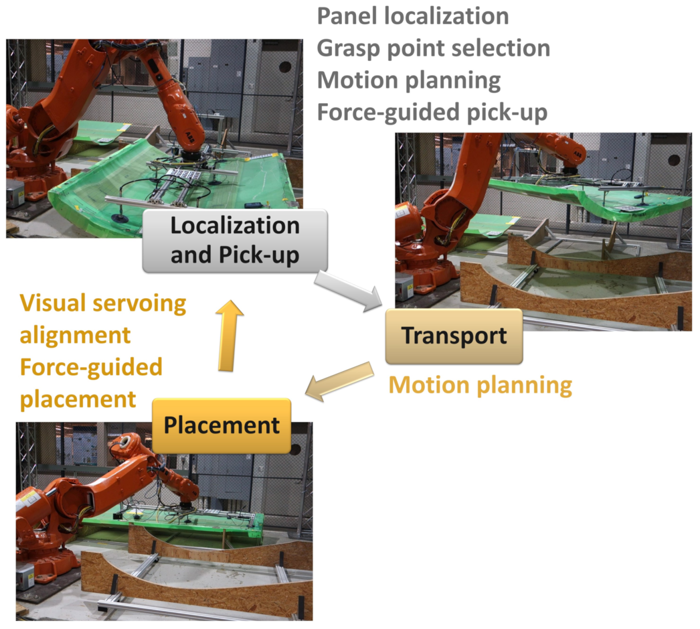
  • Panel Localization and Pick-up: A panel is placed in an arbitrary configuration in a pick-up area. The system detects the panel and identifies its location. The robot then securely and gently picks up the panel.
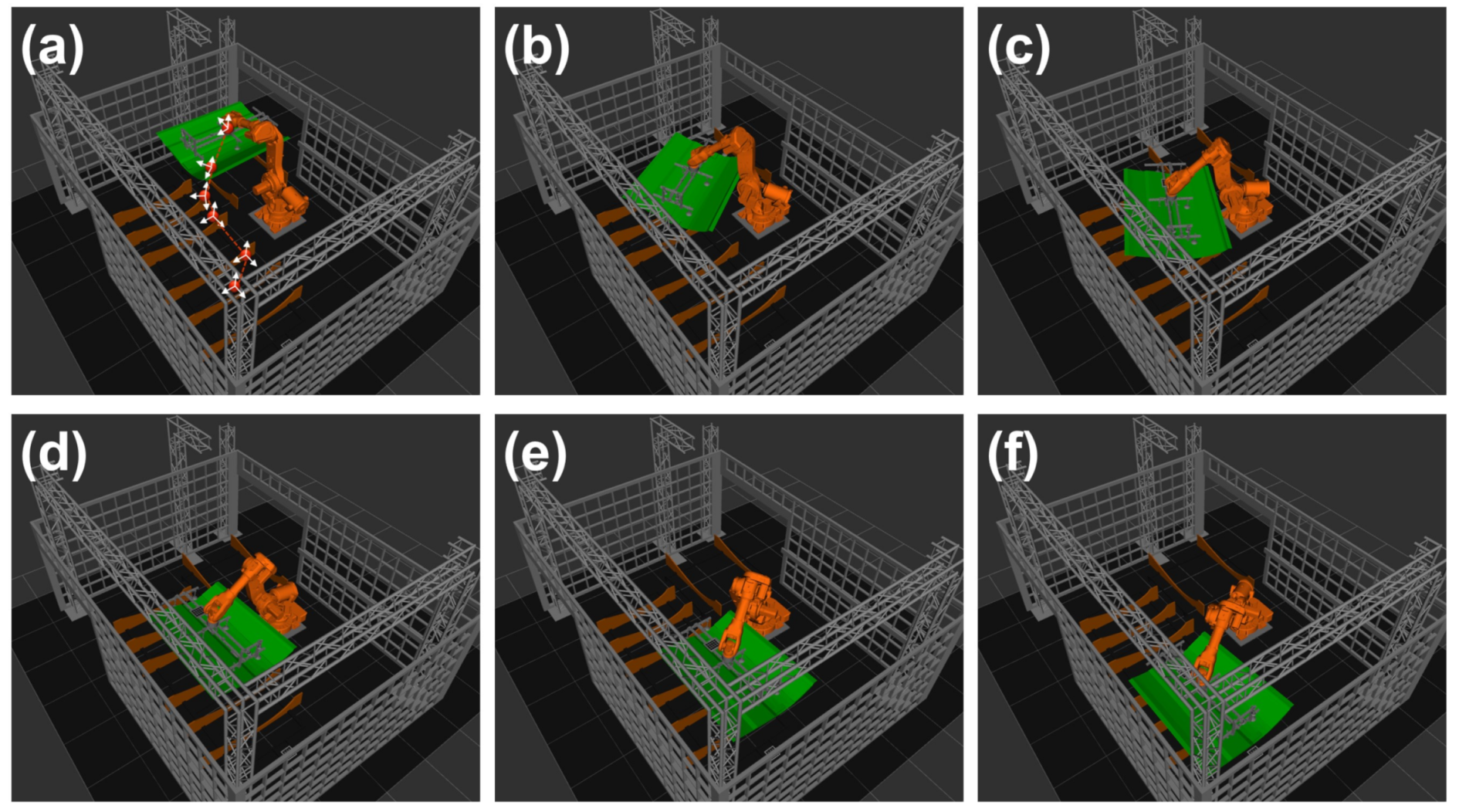
  • Panel Transport: The robot transports the panel quickly, without excessive vibration, to the assembly area.
  • Panel Placement: The robot accurately and gently places the panel and returns to Step 1.
The process repeats indefinitely as long as there are panels available for pick-up and there is space in the assembly nest. The user can step through the stages or run the process autonomously. The process can be interrupted by the user or under exception conditions (e.g., excessive force in inadvertent contacts). The user can manually operate the system and then continue the automatic operation by moving to the subsequent or previous steps.
Our solution implementation involves these steps:
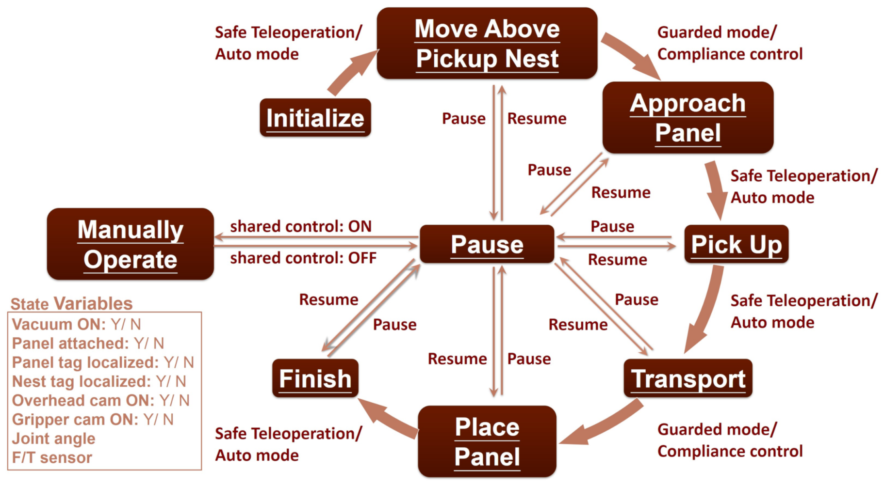
  • Construct a state machine describing the transition between the steps in the assembly process and the interaction with the operator and the occurrence of exception condition.
  • For panel pick-up localization, use the overhead camera and determine the grasp points based on the panel location and panel CAD geometry.
  • For panel placement, use the robot wrist mounted cameras for vision-guided alignment
  • For both pick-up and placement, the robot wrist-mounted force/torque sensors are used to avoid excessive contact force and alignment accuracy.
  • Identify the frequency of the fundamental vibration mode of the panel using a high speed motion capture system. Specify the robot motion bandwidth to avoid exciting the dominant panel vibrational mode.
The overall system integration and coordination is implemented in ROS. Robot motion is implemented through the external command motion mode, which allows command of the desired joint position and reading of the actual joint position at regular intervals (in our case, the External Guided Motion, or EGM, mode for the ABB robot at the 4 ms rate). This feature is used to implement sensor-based motion. The rest of this section will describe the key algorithms used in our implementation.

3.1. Resolved Motion with Quadratic Programming

The traditional teach-and-playback operation for industrial robots is not amenable for sensor-guided motion. Instead, we use the external joint position command, such as the EGM mode in the ABB robot controller, to control the robot motion. Denote the robot joint position vector as q and commanded joint position as q c . Consider a desired robot end effector spatial velocity V ( d ) (stacked angular and linear velocities). Our goal is to determine the joint motion to best match with V ( d ) while satisfying a set of inequality constraints, h I ( q ) , and joint velocity inequality constraints. Inequality constraints on q ˙ ensure the avoidance of singularities (which could cause excessive joint velocities). Configuration space inequality constraints h I ( q ) are composed of joint limits and a distance threshold d m i n that prevents collision with obstacles. For the robot motion, our approach is a combination of a global path planner and local reactive motion control. The global planner generates a desired task motion spatial velocity, V ( d ) , that satisfies all the pre-specified constraints. The local planner solves an optimization problem to find the joint motion that best meets the task space motion requirement while satisfying all the constraints. To avoid solving an optimal control problem, the inequality constraints are converted to differential constraints for Jacobian-based feedback velocity control. The end effector velocity V ( d ) may also include a user command component (through an input device such as a joystick). Because of the guard against collision and singularities, we call this process safe teleoperation. Based on our previous work in [31,32], we pose the problem as a quadratic program (QP):
min q ˙ , α r , α p | | J q ˙ α V ( d ) | | 2 + ϵ r ( α r 1 ) 2 + ϵ p ( α p 1 ) 2
subject to
d h E i d t = k E i h E i , i = 1 , , n E d h I i d t = h I i q q ˙ σ i ( h I i ) , i = 1 , , n I q ˙ min q ˙ q ˙ max ,
where J is the Jacobian matrix of the robot end effector, q ˙ is the robot joint velocity, and ( α r , α p ) specify the velocity scaling factor for the angular and linear portions (constrained to be in [ 0 , 1 ] ) with the corresponding weights ( ϵ r , ϵ p ) . The function σ i is a control barrier function [33] that is positive when h I i is in close proximity to the constraint boundary (i.e., zero). The inequality constraint h I contains joint limit and collision avoidance. We use the Tesseract trajectory optimization package [34], recently developed by the Southwest Research Institute, to compute the minimum distance, d, between the robot and the obstacles, and the location on the robot, p, corresponding to this distance. The partial robot Jacobian from joint velocity to p ˙ , J p , is used in the inequality constraint for the QP solution. For our testbed, collision checking is performed at about 10 Hz with geometry simplification.
To avoid excessive joint acceleration, we use the joint velocity in the previous frame q ˙ ( 1 ) to impose the joint acceleration bound q ¨ b o u n d :
q ˙ ( 1 ) q ¨ b o u n d t s q ˙ q ˙ ( 1 ) + q ¨ b o u n d t s ,
where t s is the sampling rate for updating the joint velocity.

3.2. User-Guided Path Planning

The MoveIt! Motion Planning Framework [35] is a popular tool for robot path planning, especially in a tight workcell such as our testbed. The current implementation of MoveIt! in ROS has over 20 different path planning algorithms from the OMPL, mostly based on some version of Probabilistic Roadmap (PRM) and Rapidly-exploring Random Trees (RRT). In multiple trials, only two algorithms, expansive-space tree planner and transition-based RRT, consistently produced feasible solutions. The probabilistic nature generates non-repeatable results, even with the same initial and final configurations. The planned paths typically involve motion of all joints, resulting in near vertical configuration of the panel, which may cause the panel slipping out of grasp.
When human users manually move the panel, they typically only use a few joints at a time to better anticipate the resulting motion and control the orientation of the load. Motivated by this observation, we adopt a user-guided path planning approach. The user specifies several intermediate panel poses for the desired motion. We then use this initial, possibly infeasible, path to generate a feasible path. The user may add or remove intermediate points to guide the robot to a desired feasible path. Once a path is found, a desired path velocity may be specified in trajectory generation and used as the specified task velocity V ( d ) in the QP controller (1).

3.3. Visual Servoing

After the panel is picked up and transported to the assembly nest, it must be accurately placed and aligned with the adjacent panel. Since there is no fixture in the setup and the workcell is not constructed to the required precision requirement, we use the gripper camera to achieve the required alignment. We have implemented both Position-based Visual Servoing (PBVS) and Image-based Visual Servoing (IBVS) in our testbed. PBVS converts image features to 3D pose information using camera calibration, and then forms the alignment error in the Euclidean space; IBVS directly expresses the alignment error in the 2D image plane [36]. In this paper, since the target 3D pose may be estimated directly from a single camera by using the ArUco markers, we only present the PBVS results. The comparable results between PBVS and IBVS, and the multiple cameras are further reported in [37]. In our setup, the reference tag in the camera image is used to estimate the relative pose between the panel and reference frames. The robot end effector pose is updated to reduce the relative pose error to achieve the alignment requirement.

3.4. Compliant Force Control

When there is a load on the moving end effector, the readings from the force/torque (F/T) sensor mounted on the end effector will be affected by the joint configuration of the robot. The load at the F/T sensor includes the gripper and tools, and possibly the panel. The F/T sensor also has inherent bias in the reading. By moving the robot to various locations and recording the corresponding F/T values, we may estimate the mass of the load, the location of the center of mass of the load, and the F/T bias. We can then subtract the effect of the load from F/T readings, at least in a static pose.
With the load contribution removed from the F/T reading, we implement an impedance controller [38,39] to regulate the interaction force during panel placement. By specifying the mass and damper in the desired impedance (in the placement direction), we may solve for the desired placement velocity based on the contact force. Denote the corresponding desired spatial velocity by V C ( d ) (which contains the desired placement velocity and zero angular velocity). To balance the placement speed and contact force at impact, we schedule the force setpoint based on the contact condition.

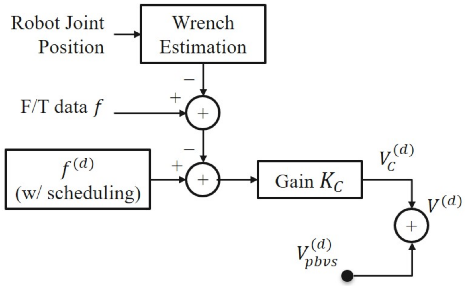
3.5. Combined Vision and Force Guided Motion

The commanded overall robot end effector motion is determined by the combination of visual servoing, V p b v s ( d ) and compliance force control V f ( d ) using the compensated F/T measurements, as shown in Figure 3. It is then used in (1) to generate the robot joint motion to achieve both motion and force control objectives while satisfying all constraints.

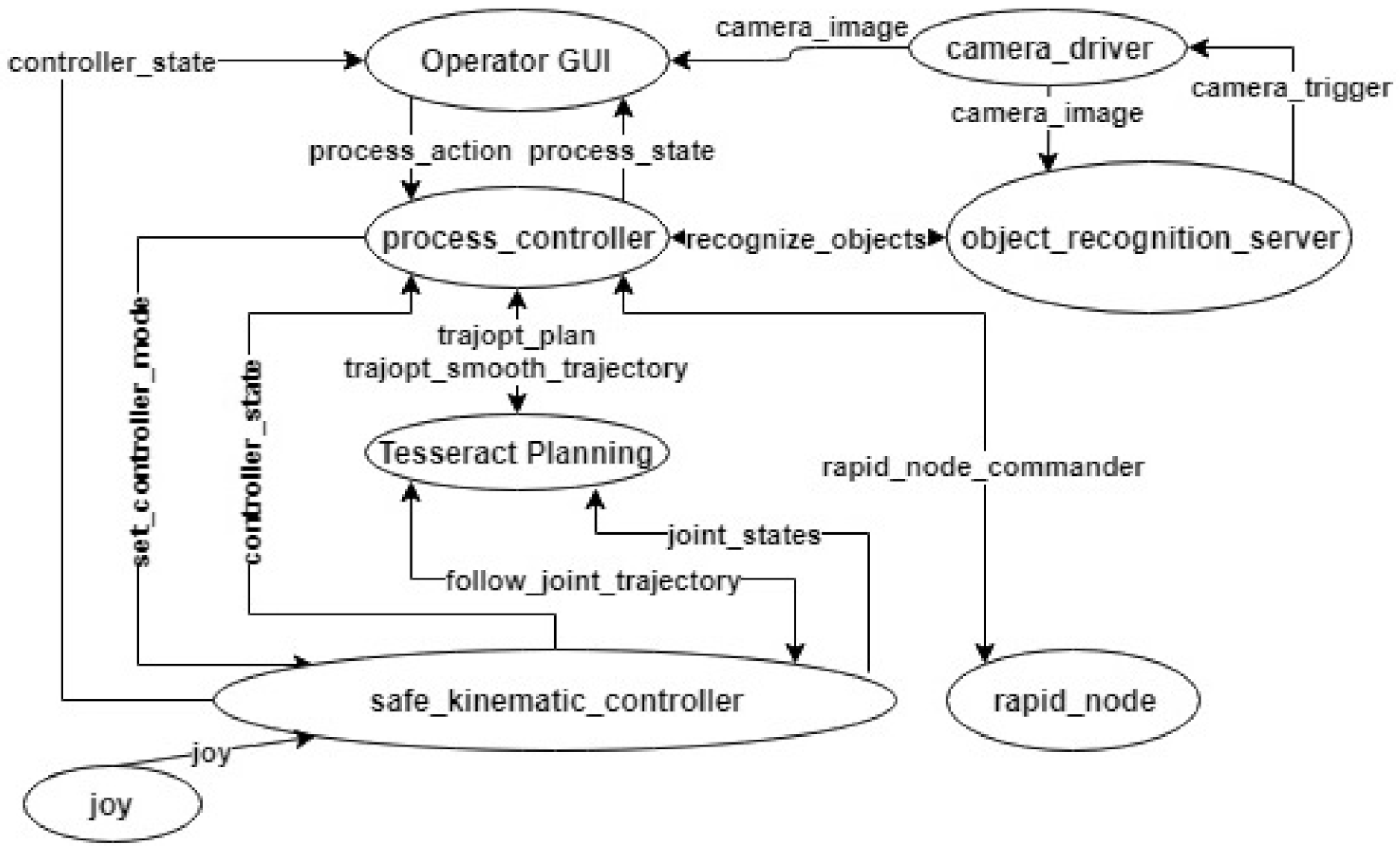
4. Software Architecture

The state machine for the overall assembly process is shown in Figure 4. The state transition is executed in either safe teleoperation or autonomous mode with vision and force guidance. We design the user interface to allow the user to interact with the state machine. The user can step through the operations, run the process autonomously in a supervisory mode, or interrupt and take over in the safe teleoperation mode. The interface allows the user to view system status information, plot force-torque and robot joint angles, and save process data for later analysis. The progression between states may be paused at any point if intervention is needed. The step can then be played back or resumed by replanning the trajectory without restarting the whole process. We implement the user interface to the state machine using QT through the ROS RQT package.
The overall software architecture of the system uses multiple levels of control to operate the system as shown in Figure 5. At the lowest level is the RAPID node that sends joint angle commands and RAPID [40] signals to the robot controller. This node receives command signals from the safe_kinematic_controller (which executes the QP motion control (1)) and interacts with most of the lower level systems necessary for taking commands in from multiple sources and moving the robot accordingly. The safe_kinematic_controller first establishes the current mode of operation of the robot, which decides which inputs are used to move the robot. The safe_kinematic_controller can also take input from the joystick to use in either joint, Cartesian, cylindrical, or spherical teleoperation, as well as for shared control of the robot.
The controller also has a Tesseract planning environment integrated into it and uses global trajectory optimization [30,34] to plan motions that are executed by joint trajectory action server calls. It can also receive directly published external set points from a ROS topic. The controller also publishes joint state messages and controller state messages that contain the F/T sensor data as well as the robot joint angles. The simulation model is built as one move group interface, which has the collision models loaded in to allow planning of motion within the robot space. The move group receives joint state information from the safe_kinematic_controller to update the position of the robot using the robot state publisher, and it also takes in transforms from the payload manager, which manages the loaded panels, to update the location of panels to be placed within the workcell. The move group can receive commands from the process controller, a higher level controller that utilizes a state machine design based on that shown in Figure 4. The process controller executes most movement trajectories utilizing the move group execute trajectory action server and takes commands to move between states using another action server interface. However, the transport path and panel placement steps are executed using separate processes, which utilize the safe_kinematic_controller with external set point motion to precisely execute robot motions and decrease overall motion planning time.
For the initial panel pickup, the process controller makes a service call to the object recognition server to localize the panel in the pickup nest using the camera driver node. It then returns the location of the panel in the robot frame. The operator Graphical User Interface (GUI) is the highest level controller. It handles and simplifies the many calls made to the process controller to perform the full process. The operator GUI relies on threaded action calls to interact with the process controller allowing the operator GUI to maintain focus and allow users to pause, play back, and resume at any point of the process.

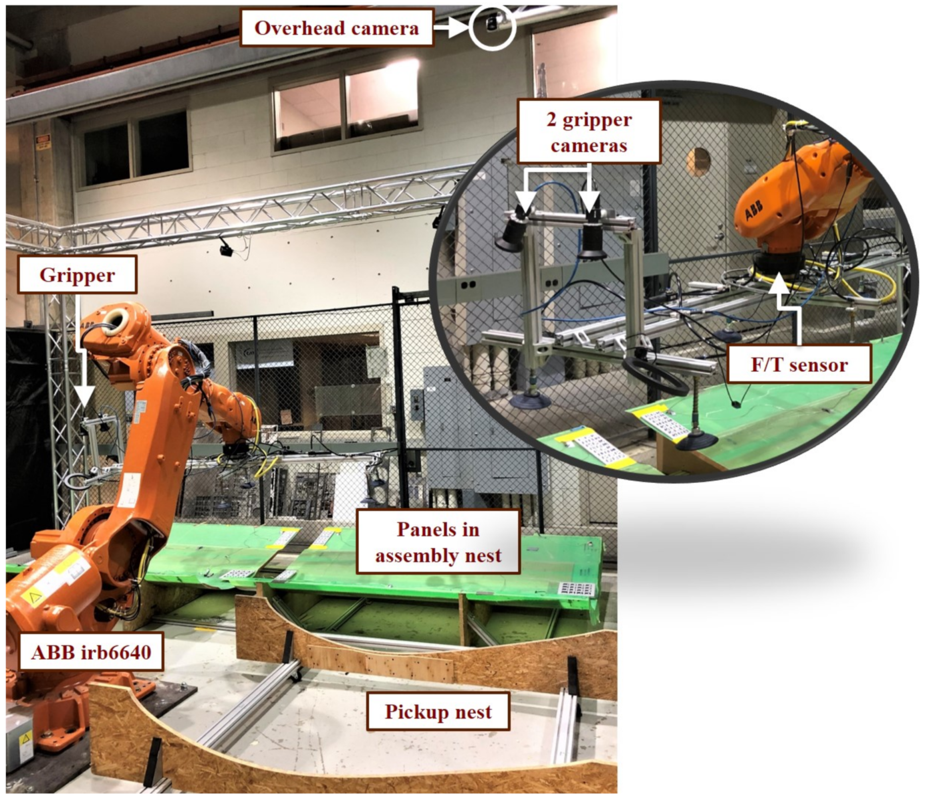
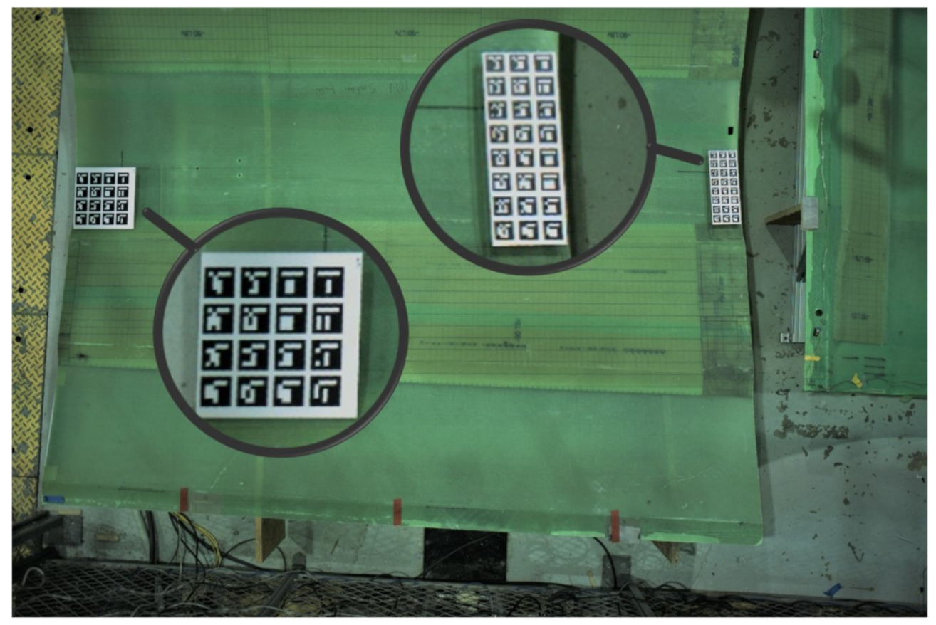
5. Testbed and Hardware

The experimental testbed shown in Figure 1 is designed to approximate a real factory environment. The testbed contains an ABB IRB-6640 robot equipped with a 6-suction-cup vacuum gripper. The gripper is mounted with an ATI F/T sensor, two cameras, a dimmable light, and three pairs of pressure sensors used to monitor the engagement of the suction cups to the panel. There is also an overhead camera over the pick-up area. There are two different types of panels, representing root (thicker) and mid-section portions of the structure. Each panel weighs approximately 35 kg. The robot has a payload capacity of 180 kg, 0.07 mm position repeatability, and 0.7 mm path repeatability. The robot controller supports the external guided motion (EGM) mode for joint motion command and joint angle access at a rate of 4 ms. A six-axis F/T sensor Omega160 from ATI Corp. is mounted at the center of the end effector. The sampling rate is up to 7 KHz.
A FLIR Vision camera, the Blackfly S Color 20.0 (5472 × 3648) MP USB3 Vision, is placed overhead above the pick-up nest. Using a Computar 1.1′′ 12 mm f/2.8 12MP ultra low distortion lens, the estimated field of view from 3.2 m is 3.768 m × 2.826 m, and hence each pixel is approximately 1.15 mm/pixel × 1.28 mm/pixel in the target area (the lens decreases the resolution by 40%). This camera is used to locate the panel at the pickup nest for the initial pickup, requiring a bigger field of view and coarser localization. Two FLIR Vision Blackfly S Color 5.0 (2448 × 2048) MP USB3 Vision cameras are mounted at one end of the gripper. Using a Tamron 1.1′′ 8 mm f/1.8 12MP fixed focal lens, the estimated field of view from 0.5 m distance is 0.88 m × 0.66 m; hence the resolution is 0.36 mm/pixel × 0.32 mm/pixel in the target area. The gripper cameras move with the end effector at an offset distance, and 10-m active USB3 extension cables from Newnex (FireNEXAMAF10M) ensure that the camera data are reliably transmitted without attenuation from the long distance. In this paper, we only use one camera on the gripper for PBVS.
After the panel is picked up and moved above the assembly nest, the gripper camera, which only has a small portion of view blocked by the panel, localizes the assembly nest with respect to the panel with fine resolution for placement. We use a precisely manufactured checkerboard with a 30 mm × 30 mm grid to calibrate the high resolution cameras, resulting in a re-projection error of 0.13 pixels. To accurately detect, identify and localize objects in the image frame, we selected an open source Augmented Reality (AR) library based on OpenCV, called ArUco markers. The 3D position and orientation of each marker can be quickly extracted from a single camera viewpoint. The markers are printed using a 600 dpi resolution printer on vinyl paper and attached to flat acrylic boards in order to minimize errors. We combined multiple markers as shown in Figure 6 onto a marker board for higher accuracy localization. The marker size is arbitrarily determined as long as it can be visible to the cameras. The marker pose is determined to avoid contacting the suction cups during pickup and placement. Note that the markers are allowed to laser inked on the panels in the real factory, and the concept applies to other 3D pose estimation methods using features or edges directly from the panel. Based on this setup, the gripper camera accuracy is [0.26, 0.19, 1.46] mm in the camera ( x , y , z ) directions. We are mainly concerned about the ( x , y ) accuracy, since compliance control addresses the z-direction motion.

6. Experimental Results

6.1. Panel Pickup

With the calibrated overhead camera, the pick-up position and orientation of the panel are estimated based on the marker board mounted on the panel. The gripper is first moved above the panel. The gripper uses force control to make contact with the panel until the force setpoint 250 N is reached. The six suction cups are then engaged to attach the panel to the gripper and lift it up.

6.2. Transport Path Generation

As described in Section 3.2, the operator selects a set of waypoints (which may not be feasible) which the path planner tries to meet while observing the collision avoidance and other inequality constraints such as joint limits, and velocity and acceleration bounds. Figure 7 shows the operator selecting six waypoints offline. The straight line segments connecting these points serve as the starting point to generate a feasible path.
The control barrier function σ i is tuned to allow the robot to decelerate at 0.5 m away from the obstacle with a 0.25-m buffer size. The QP optimization is solved with cvx and quadprog libraries in Python.

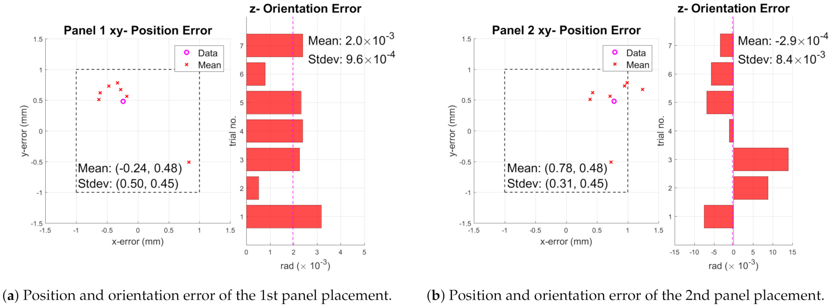
6.3. Panel Placement

The system accuracy is most critical in the placement stage. The first panel is placed based on the reference tag on the assembly nest. The second panel is placed based on the tag on the first panel. We conducted seven trials for the two panels for statistical performance analysis. The main gripper camera pointing downward is used for the placement task.

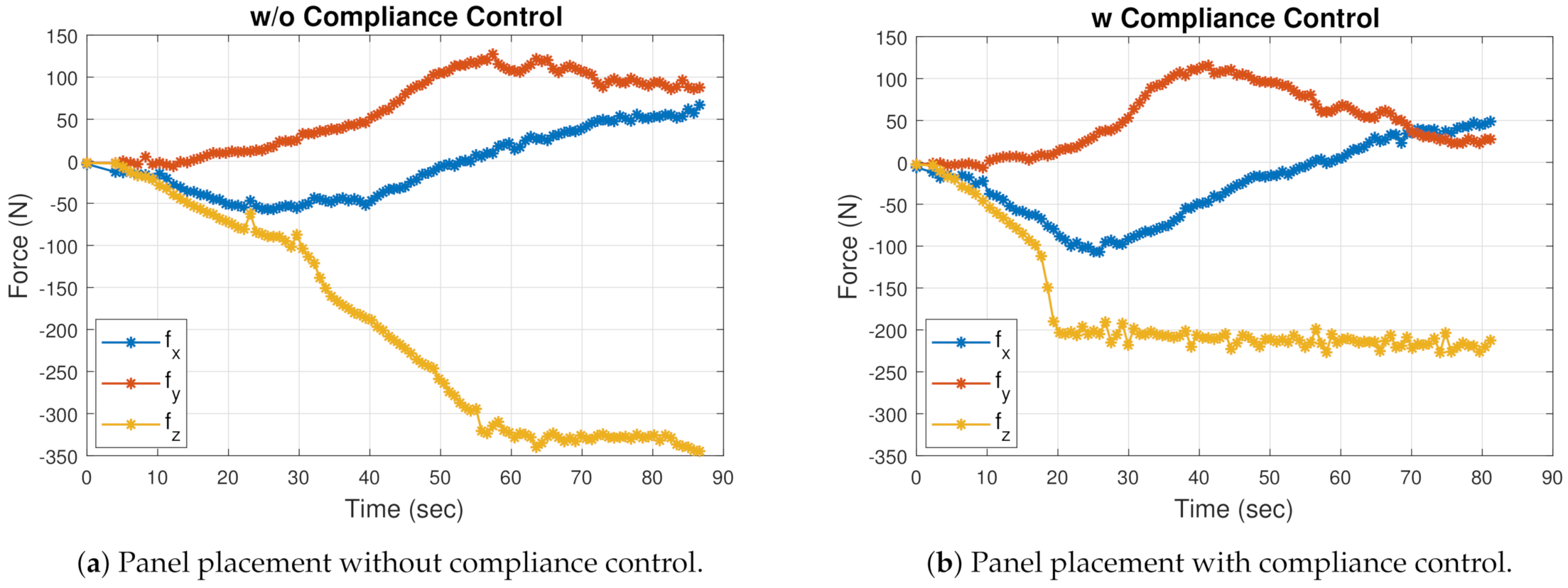
6.3.1. Compliance Control

The compliance controller is applied for the z-axis motion. The desired force is scheduled from the initial 150 N before contact to 200 N post contact to allow a fast but gentle placement. Figure 8b shows that the compliance controller helps to maintain the compliance force in the z-axis at −200 N while the panel is placed in the nest. Figure 8a shows the case when the panel is placed with only vision guidance without compliance control. Such excessive contact force could result in panel damage.

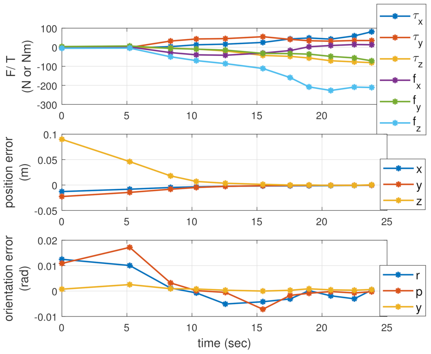
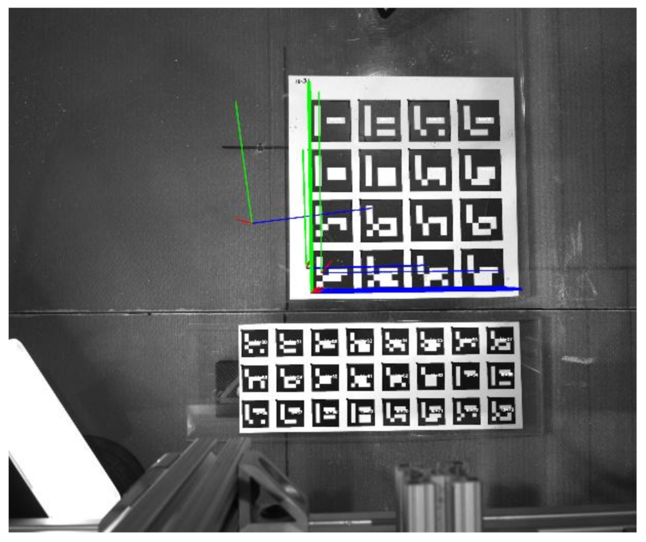
6.3.2. Placement with PBVS and Compliance Control

After the panel is transported to the assembly nest, the panel will first be moved to about 5 cm above the nest based on the pose from the reference marker fixed on the assembly nest or the previously placed panel. Then, PBVS is implemented to match the 3 × 8 panel marker pose with respect to the reference marker pose, which is calibrated by placing the panel in the desired location manually.
We used a motion capture system from PhaseSpace for accuracy verification. In the motion capture system, eight cameras are deployed around the testbed, which are able to detect the 3D positions of the LEDs mounted on each panel. The resolution from this motion capture system is approximately 0.1 mm at a rate of 220 Hz [41].
PBVS and compliance force control are used together for placement control as in Figure 3. In order to achieve sub-millimeter accuracy, the error gradually converges until the detected error is smaller than 1 mm. The PBVS gain is tuned for fast and smooth convergence. The motion and force convergence during placement is shown in Figure 9. The contact force in the z-direction converges to about −200 N, and both the position and orientation errors converge to an acceptable level. In Figure 10, the second panel is assembled with respect to the first panel that was previously placed. From the view of the gripper camera, one set of 4 × 4 markers is firmly fixed to the placed panel (top), and another set of 3 × 8 markers is attached to the panel that is moved simultaneously with the gripper and therefore remains static in the image (bottom). The desired marker pose is obtained in advance. During the PBVS placement, the robot is guided to match the current reference marker estimated from the panel marker to the desired relative marker pose.
We executed the placement process seven times for the two panels and report the planar error results in Figure 11 from the motion capture system. Our main focus is on the position error in the ( x , y ) axes. The z direction is controlled by the contact force against the assembly nest. The results of the first panel are all within 1 mm with the mean error (−0.24, 0.48) mm and standard deviation (0.5, 0.45) mm. The placement of the second panel shows one run violating the 1 mm accuracy requirement in the x-axis. This is likely due to camera calibration error. The mean error is (0.78, 0.52) mm with standard deviation (0.31, 0.18) mm.

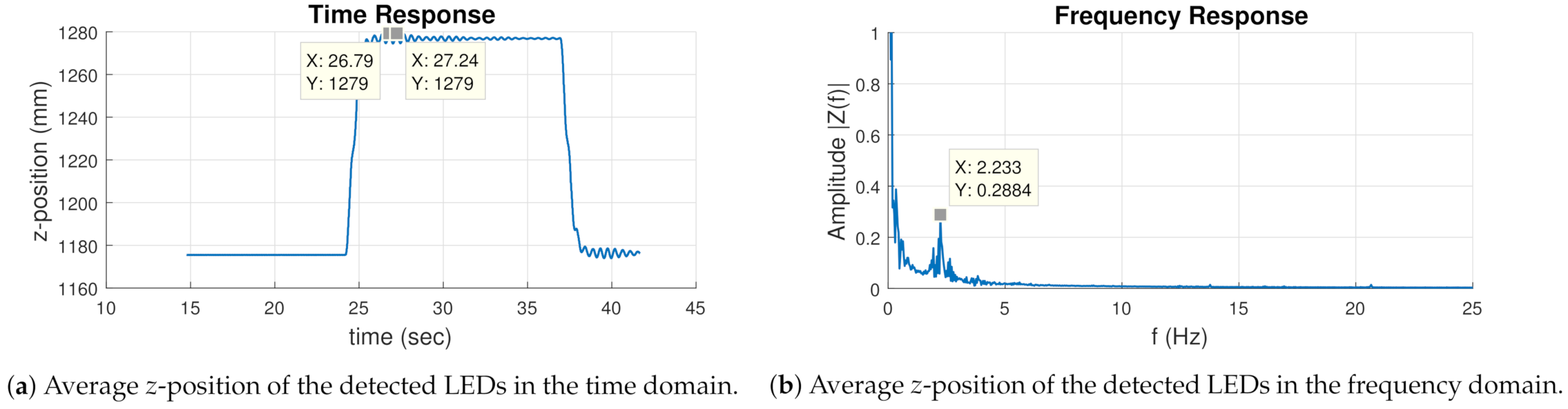
6.3.3. Panel Vibration Observation

During the process, it is desirable to avoid panel vibration while moving the flexible object. In the experiment in this section, the robot is controlled to deliberately cause jerkiness in the z-axis of the panel. which is temporarily mounted with a set of twelve LEDs from the motion capture system. The measured LED coordinate is shown in Figure 12a, and the corresponding spectrum in Figure 12b, showing a dominant flexible mode at 2.23 Hz. We adjust the bandwidth of the commanded motion to avoid exciting this mode. Other command input shaping techniques (e.g., using a notch filter) may be used to avoid the vibration mode excitation.

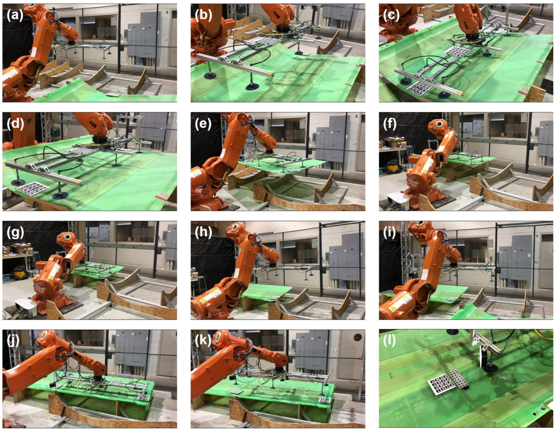
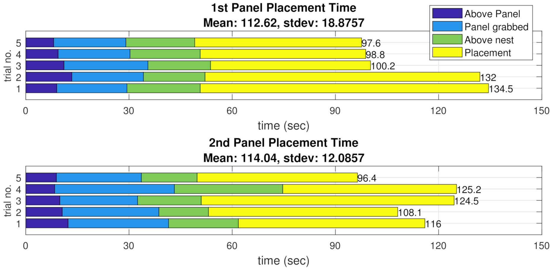
6.4. Continuous Panel Assembly Task

The entire continuous process of picking and placing the two panels in the assembly nest is demonstrated in Figure 13. In (a), the robot starts at an initial pose when the first panel is in the pickup nest ready for pickup. In (b), the overhead camera detects the position and orientation of the panel and publishes the information to the robot, which then moves above the panel. In (c), the robot makes contact with the panel with all six suction cups well engaged. The robot picks up the panel in (d) and transports it to the first assembly nest in (e,f). In (g), the panel is finally placed in the assembly nest based on the vision and force guidance. The whole procedure is reset and prepared for the second panel in (h) and (i). Following a similar procedure from (b) to (g), the second panel is picked and placed in the second assembly nest as shown in (j). Then, in (k), the robot releases the suction and leaves the panels in the nest with the seam between the two panels pictured in (l). Note that when interference is needed, the process can be stopped, played back, or resumed at any point during the process from the GUI as discussed in Section 4. The video of the entire assembly process may also be found online in [42].
We conducted five rounds of the continuous process for the timing test in Figure 14. The total placement time includes the motion of the panel to the initial position in close proximity to the assembly nest, transport of the panel to the assembly nest, and placement of the panel using PBVS. Since there is contact involved in picking up and placing the panel, the robot is commanded to move more slowly to avoid damage, and hence the longer times for these stages. Overall, it takes an average of 112.62 s with a standard deviation of 18.88 s for the first panel; and 114.04 s with a standard deviation of 12.09 s for the second panel. The variation may come from the various pickup panel poses resulting in different complexity for the following transport and placement tasks particularly for the path planning. The result shows vast improvement over the manual operation in terms of speed and accuracy. Our trained operator spent more than 6 minutes to transport and place down one panel, but could not properly align the panel solely based on the image feeds without any fixture. Further optimization could further improve the robustness and cycle time of the process.

7. Conclusions and Future Work

This paper presents an industrial robotic system for large composite assembly using force and vision guidance, demonstrated in both simulation and experiments. Using the external commanded motion mode of the robot, the force and vision information is used to adjust the robot motion to achieve tight alignment tolerance. Simulation with force and vision servoing incorporated is used to validate the software and tune the algorithms before the implementation in the physical testbed. The assembly process is operated through a user-friendly GUI, which allows the user to pause, playback, and resume at any point without restarting the whole process. The project is implemented in ROS and is available via open-source [43]. Though the current implementation uses the ABB robot, it is extensible to other industrial robots and sensors with minimal modifications. Currently, human workers are excluded from the caged robot cell. We are using multiple point cloud sensors in the work cell to detect human movement and in future work will adjust the robot motion to ensure worker safety.

Author Contributions

Conceptualization, Y.-C.P.; methodology, Y.-C.P., S.C., D.J., J.W., W.L., G.S., R.J.R., J.T., S.N. and J.T.W.; software, Y.-C.P., S.C., D.J., J.W. and W.L.; validation, Y.-C.P., S.C., D.J., J.W. and W.L.; resources, J.W.; writing—original draft preparation, Y.-C.P., S.C., D.J., R.J.R. and J.T.W.; writing—review and editing, Y.-C.P., S.C. and J.W.; supervision, J.T.W.; project administration, J.T.W.; funding acquisition, J.T.W. and S.N. All authors have read and agreed to the published version of the manuscript.

Funding

This work was supported in part by Subaward No. ARM-TEC-17-QS-F-01 from the Advanced Robotics for Manufacturing (“ARM”) Institute under Agreement Number W911NF-17-3-0004 sponsored by the Office of the Secretary of Defense. ARM Project Management was provided by Matt Fischer. The views and conclusions contained in this document are those of the authors and should not be interpreted as representing the official policies, either expressed or implied, of either ARM or the Office of the Secretary of Defense of the U.S. Government. The U.S. Government is authorized to reproduce and distribute reprints for Government purposes, notwithstanding any copyright notation herein. This research was also supported in part by the the New York State Empire State Development Division of Science, Technology and Innovation (NYSTAR) Matching Grant Program under contract C170141.

Institutional Review Board Statement

Not applicable.

Informed Consent Statement

Not applicable.

Data Availability Statement

Publicly available datasets were analyzed in this study. This data can be found here: https://github.com/rpiRobotics/rpi_arm_composites_manufacturing (accessed on 15 February 2021). The project video can be found here: https://youtu.be/TFZpfg433n8 (accessed on 15 February 2021).

Acknowledgments

The authors would like to thank Roland Menassa for their suggestion of this project area and their initial work on segmented panel assembly, Mark Vermilyea and Pinghai Yang for input in the project, Steve Rock for help with the testbed safety implementation, and Ken Myers for help with the testbed setup.

Conflicts of Interest

The authors declare no conflict of interest.

References

  1. Smith, K.J.; Griffin, D.A. Supersized Wind Turbine Blade Study: R&D Pathways for Supersized Wind Turbine Blades; Technical Report; Lawrence Berkeley National Laboratory (LBNL): Berkeley, CA, USA, 2019. [CrossRef] [Green Version]
  2. ABB Robotics. Application Manual: Controller Software IRC5: RoboWare 6.04; ABB Robotics: Västerås, Sweden, 2016. [Google Scholar]
  3. Marcil, E. Motoplus-ROS Incremental Motion Interface; Yaskawa Motoman Robotics: Miamisburg, OH, USA, 2017. [Google Scholar]
  4. Stäubli. C Programming Interface for Low Level Robot Control; Stäubli: Pfäffikon, Switzerland, 2009. [Google Scholar]
  5. Schöpfer, M.; Schmidt, F.; Pardowitz, M.; Ritter, H. Open source real-time control software for the Kuka light weight robot. In Proceedings of the 2010 8th World Congress on Intelligent Control and Automation (WCICA), Jinan, China, 7–9 July 2010; pp. 444–449. [Google Scholar] [CrossRef]
  6. Quigley, M.; Conley, K.; Gerkey, B.; Faust, J.; Foote, T.; Leibs, J.; Wheeler, R.; Ng, A.Y. ROS: An open-source robot operating system. In Proceedings of the ICRA Workshop on Open Source Software, Kobe, Japan, 29 June 2009; Volume 3, p. 5. [Google Scholar]
  7. ROS-Industrial Consortium. ROS-Industrial; ROS-Industrial Consortium: Singapore, 2021. [Google Scholar]
  8. Bi, Z.M.; Zhang, W.J. Flexible fixture design and automation: Review, issues and future directions. Int. J. Prod. Res. 2001, 39, 2867–2894. [Google Scholar] [CrossRef]
  9. Pehlivan, S.; Summers, J.D. A review of computer-aided fixture design with respect to information support requirements. Int. J. Prod. Res. 2008, 46, 929–947. [Google Scholar] [CrossRef]
  10. Parvaz, H.; Nategh, M.J. A pilot framework developed as a common platform integrating diverse elements of computer aided fixture design. Int. J. Prod. Res. 2013, 51, 6720–6732. [Google Scholar] [CrossRef]
  11. Bakker, O.; Papastathis, T.; Popov, A.; Ratchev, S. Active fixturing: Literature review and future research directions. Int. J. Prod. Res. 2013, 51, 3171–3190. [Google Scholar] [CrossRef] [Green Version]
  12. Daniyan, I.A.; Adeodu, A.O.; Oladapo, B.I.; Daniyan, O.L.; Ajetomobi, O.R. Development of a reconfigurable fixture for low weight machining operations. Cogent Eng. 2019, 6, 1579455. [Google Scholar] [CrossRef]
  13. Schlather, F.; Hoesl, V.; Oefele, F.; Zaeh, M.F. Tolerance analysis of compliant, feature-based sheet metal structures for fixtureless assembly. J. Manuf. Syst. 2018, 49, 25–35. [Google Scholar] [CrossRef]
  14. Michalos, G.; Makris, S.; Papakostas, N.; Mourtzis, D.; Chryssolouris, G. Automotive assembly technologies review: Challenges and outlook for a flexible and adaptive approach. J. Manuf. Sci. Technol. 2010, 2, 81–91. [Google Scholar] [CrossRef]
  15. Hoska, D.R. Fixturless assembly manufacturing. Manuf. Eng. 1988, 100, 49–54. [Google Scholar]
  16. Plut, W.J.; Bone, G.M. Limited mobility grasps for fixtureless assembly. In Proceedings of the IEEE International Conference on Robotics and Automation (ICRA), Minneapolis, MN, USA, 22–28 April 1996; Volume 2, pp. 1465–1470. [Google Scholar]
  17. Bone, G.M.; Capson, D. Vision-guided fixtureless assembly of automotive components. Robot. Comput. Integr. Manuf. RCIM 2003, 19, 79–87. [Google Scholar] [CrossRef]
  18. Yeung, B.H.B.; Mills, J.K. Design of a six DOF reconfigurable gripper for flexible fixtureless assembly. IEEE Trans. Syst. Man Cybern. 2004, 34, 226–235. [Google Scholar] [CrossRef]
  19. Langley, C.S.; D’Eleuterio, G.M.T. Neural Network-based Pose Estimation for Fixtureless Assembly. In Proceedings of the 2001 IEEE International Symposium on Computational Intelligence in Robotics and Automation, Banff, AB, Canada, 29 July–1 August 2001; pp. 248–253. [Google Scholar]
  20. Corona-Castuera, J.; Rios-Cabrera, R.; Lopez-Juarez, I.; Pena-Cabrera, M. An Approach for Intelligent Fixtureless Assembly: Issues and Experiments. In Proceedings of the Mexican International Conference on Artificial Intelligence (MICAI), Monterrey, Mexico, 14–18 November 2005; pp. 1052–1061. [Google Scholar]
  21. Pena-Cabrera, M.; Lopez-Juarez, I.; Rios-Cabrera, R.; Corona, J. Machine vision approach for robotic assembly. Assem. Autom. 2005, 25, 204–216. [Google Scholar] [CrossRef]
  22. Navarro-Gonzalez, J.; Lopez-Juarez, I.; Rios-Cabrera, R.; Ordaz-Hernandez, K. On-line knowledge acquisition and enhancement in robotic assembly tasks. Robot. Comput. Integr. Manuf. RCIM 2015, 33, 78–89. [Google Scholar] [CrossRef]
  23. Jayaweera, N.; Webb, P. Adaptive robotic assembly of compliant aero-structure components. Robot. Comput. Integr. Manuf. RCIM 2007, 23, 180–194. [Google Scholar] [CrossRef]
  24. Tingelstad, L.; Capellan, A.; Thomessen, T.; Lien, T.K. Multi-Robot Assembly of High-Performance Aerospace Components. IFAC Proc. Vol. 2012, 45, 670–675. [Google Scholar] [CrossRef]
  25. Park, H.; Bae, J.H.; Park, J.H.; Baeg, M.H.; Park, J. Intuitive peg-in-hole assembly strategy with a compliant manipulator. In Proceedings of the IEEE ISR 2013, Seoul, Korea, 24–26 October 2013; pp. 1–5. [Google Scholar]
  26. Fang, S.; Huang, X.; Chen, H.; Xi, N. Dual-arm robot assembly system for 3C product based on vision guidance. In Proceedings of the 2016 IEEE International Conference on Robotics and Biomimetics (ROBIO), Qingdao, China, 3–7 December 2016; pp. 807–812. [Google Scholar]
  27. Sucan, I.A.; Moll, M.; Kavraki, L.E. The Open Motion Planning Library. IEEE Robot. Autom. Mag. 2012, 19, 72–82. [Google Scholar] [CrossRef] [Green Version]
  28. Ratliff, N.; Zucker, M.; Bagnell, J.A.; Srinivasa, S. CHOMP: Gradient optimization techniques for efficient motion planning. In Proceedings of the 2009 IEEE International Conference on Robotics and Automation (ICRA), Kobe, Japan, 12–17 May 2009; pp. 489–494. [Google Scholar] [CrossRef] [Green Version]
  29. Kalakrishnan, M.; Chitta, S.; Theodorou, E.; Pastor, P.; Schaal, S. STOMP: Stochastic trajectory optimization for motion planning. In Proceedings of the 2011 IEEE International Conference on Robotics and Automation (ICRA), Shanghai, China, 9–13 May 2011; pp. 4569–4574. [Google Scholar] [CrossRef]
  30. Schulman, J.; Duan, Y.; Ho, J.; Lee, A.; Awwal, I.; Bradlow, H.; Pan, J.; Patil, S.; Goldberg, K.; Abbeel, P. Motion planning with sequential convex optimization and convex collision checking. Int. J. Robot. Res. 2014, 33, 1251–1270. [Google Scholar] [CrossRef] [Green Version]
  31. Chen, S.; Peng, Y.C.; Wason, J.; Cui, J.; Saunders, G.; Nath, S.; Wen, J.T. Software Framework for Robot-Assisted Large Structure Assembly. In Proceedings of the ASME 13th MSEC, College Station, TX, USA, 18–22 June 2018. Paper V003T02A047. [Google Scholar] [CrossRef]
  32. Lu, L.; Wen, J.T. Human-directed coordinated control of an assistive mobile manipulator. Int. J. Intell. Robot. Appl. IJIRA 2017, 1, 104–120. [Google Scholar] [CrossRef]
  33. Ames, A.D.; Xu, X.; Grizzle, J.W.; Tabuada, P. Control barrier function based quadratic programs for safety critical systems. IEEE Trans. Autom. Control 2016, 62, 3861–3876. [Google Scholar] [CrossRef]
  34. Armstrong, L. Optimization motion planning with Tesseract and TrajOpt for industrial applications; ROS-Industrial Consortium: San Antonio, TX, USA, 2018. [Google Scholar]
  35. Chitta, S.; Sucan, I.; Cousins, S.B. MoveIt! ROS topics. IEEE Robot. Autom. Mag. 2012, 19, 18–19. [Google Scholar] [CrossRef]
  36. Chaumette, F.; Hutchinson, S. Visual servo control. I. Basic approaches. IEEE Robot. Autom. Mag. 2006, 13, 82–90. [Google Scholar] [CrossRef]
  37. Peng, Y.C.; Jivani, D.; Radke, R.J.; Wen, J. Comparing Position- and Image-Based Visual Servoing for Robotic Assembly of Large Structures. In Proceedings of the 2020 IEEE 16th International Conference on Automation Science and Engineering (CASE), Hong Kong, China, 20–21 August 2020; pp. 1608–1613. [Google Scholar] [CrossRef]
  38. Hogan, N. Impedance control: An approach to manipulation. In Proceedings of the 1984 American Control Conference (ACC), San Diego, CA, USA, 6–8 June 1984; pp. 304–313. [Google Scholar]
  39. Peng, Y.C.; Carabis, D.S.; Wen, J.T. Collaborative manipulation with multiple dual-arm robots under human guidance. Int. J. Intell. Robot. Appl. IJIRA 2018, 2, 252–266. [Google Scholar] [CrossRef]
  40. ABB Robotics. Operating Manual—Introduction to RAPID; ABB Robotics: Västerås, Sweden, 2007. [Google Scholar]
  41. PhaseSpace. PhaseSpace Impulse X2E: Data Sheet; PhaseSpace: San Leandro, CA, USA, 2017. [Google Scholar]
  42. Peng, Y.C. Robotic Assembly of Large Structures with Vision and Force Guidance. Available online: https://youtu.be/TFZpfg433n8 (accessed on 15 February 2020).
  43. Lawler, W.; Wason, J. RPI ARM Composites Manufacturing. Available online: https://github.com/rpiRobotics/rpi_arm_composites_manufacturing (accessed on 15 February 2020).
Figure 1. The experimental testbed approximates part of the actual factory manufacturing scenario. A robot picks up an incoming panel from the pick-up nest and transports it to the placement nest where it needs to be aligned to a reference frame or with another panel.
Applsci 11 02669 g001
Figure 2. The assembly process consists of three major steps: panel localization and pick-up, panel transport, and panel placement. Vision feedback is used for localization and alignment. Force feedback is used for gentle contact and placement. Motion planning is required for collision-free panel transport.
Applsci 11 02669 g002
Figure 3. The vision-based velocity command V p b v s ( d ) is combined with the force accommodation velocity command V C ( d ) to generate the overall velocity command V ( d ) for the robot end effector. The force accommodation control is a generalized damper with the estimated panel gravity load removed fromthe measured force and torque.
Applsci 11 02669 g003
Figure 4. The state transition diagram of the assembly process allow continuous operation to assemble incoming panels to the existing panels. It also allows operator to pause for manual operations and resume after completion. The operator can also manually transition the system to a different state. The state of the system consists of the robot pose, sensor measurements, and end effector conditions.
Applsci 11 02669 g004
Figure 5. The ROS software architecture implements the entire process, including user interface, motion planning (using Tesseract), vision service and object recognition, robot kinematic control, and robot interface.
Applsci 11 02669 g005
Figure 6. View from the overhead camera using multiple ArUco markers for the panel pose estimation. The estimated panel pose is then used to determine the grasp location of the vacuum gripper.
Applsci 11 02669 g006
Figure 7. Transport path generated by using the Resolved Motion method in Section 3.1 with user selected waypoints. (a) The user specifies a series of waypoints; from (bf), the robot follows through the path generated by the input waypoints.
Applsci 11 02669 g007
Figure 8. (a) Panel placement without compliance control risks high contact force (robot moves in the z direction for placing the panel in the assembly nest). (b) With compliance control, the placement force is regulated to the specified 200 N.
Applsci 11 02669 g008
Figure 9. Under force and vision feedback, the placement force converges to the specified 200 N to ensure secure seating in the nest, and the position and orientation alignment is achieved to within 1 mm and 0.1 degree, respectively.
Applsci 11 02669 g009
Figure 10. Convergence of the panelmarker pose to the referencemarker pose viewed fromthe gripper camera. The coordinate frames indicate the poses of the reference marker during the convergence while the panel marker is relatively stationary to the gripper camera.
Applsci 11 02669 g010
Figure 11. Panel placement errors over 7 trials indicates alignment error within 1 mm for the x-y position and 0.1 degree for orientation.
Applsci 11 02669 g011
Figure 12. Panel vibration, measured by the motion capture system, shows the dominant vibrational mode around 2.23 Hz. Robot motion bandwidth is chosen below this mode to avoid panel oscillation.
Applsci 11 02669 g012
Figure 13. Snapshots of the assembly process: (a) Robot at initial pose and first panel ready for pickup in the pickup nest. (b) Panel pose estimated by overhead camera; robot moving to the pickup pose. (c) Robot approaching panel until all six suction cups well engaged. (d) Robot picking up panel. (e,f) Panel transported to above the first assembly nest. (g) Panel placed in the assembly nest based on vision and force guidance. (h) Robot returning to initial pose. (i) Second panel manually brought in and ready to be picked up. (j) Second panel picked up, transported, and placed in the second assembly nest following the same procedures as steps (bg). (k) Robot releasing the panel. (l) Closer look at the seam between the placed panels.
Applsci 11 02669 g013
Figure 14. Timing data of end-to-end process of assembling two panels shows the most amount of time is spent at placement in order to achieve the required accuracy.
Applsci 11 02669 g014
Publisher’s Note: MDPI stays neutral with regard to jurisdictional claims in published maps and institutional affiliations.

