Article

Hybrid Spine Simulator Prototype for X-ray Free Pedicle Screws Fixation Training

1
Information Engineering Department, University of Pisa, 56126 Pisa, Italy
2
Department of Computer Science, Kettering University, Flint, MI 48504, USA
3
1st Orthopaedic and Traumatology Division, Department of Translational Research and of New Surgical and Medical Technologies, University of Pisa, 56124 Pisa, Italy
*
Author to whom correspondence should be addressed.
Appl. Sci. 2021, 11(3), 1038; https://doi.org/10.3390/app11031038
Submission received: 28 December 2020 / Revised: 14 January 2021 / Accepted: 21 January 2021 / Published: 24 January 2021
(This article belongs to the Special Issue Serious Games and Mixed Reality Applications for Healthcare)

Abstract

:
Simulation for surgical training is increasingly being considered a valuable addition to traditional teaching methods. 3D-printed physical simulators can be used for preoperative planning and rehearsal in spine surgery to improve surgical workflows and postoperative patient outcomes. This paper proposes an innovative strategy to build a hybrid simulation platform for training of pedicle screws fixation: the proposed method combines 3D-printed patient-specific spine models with augmented reality functionalities and virtual X-ray visualization, thus avoiding any exposure to harmful radiation during the simulation. Software functionalities are implemented by using a low-cost tracking strategy based on fiducial marker detection. Quantitative tests demonstrate the accuracy of the method to track the vertebral model and surgical tools, and to coherently visualize them in either the augmented reality or virtual fluoroscopic modalities. The obtained results encourage further research and clinical validation towards the use of the simulator as an effective tool for training in pedicle screws insertion in lumbar vertebrae.

1. Introduction

Simulation is becoming an essential part of surgical training as it allows for repetitive practice in a safe controlled environment whose complexity can be tailored to the trainee’s expertise level and needs. Currently, there is a consensus among the orthopedic community that the acquisition of trainees’ surgical skills should commence in a simulated training environment prior to progression to the surgical room [1] in order to improve surgical outcomes and patient safety.
Pedicle screws fixation, the gold standard among posterior instrumentation techniques to stabilize spine fusion, is a technically demanding procedure which requires long training to avoid catastrophic neurovascular complications due to screw misplacement. The risk of misplacement, which is exacerbated by the complexity of the anatomy (e.g., deformity of the spine together with dysplastic anatomy) can be very high, indeed literature studies report an error rate of 10–40% [2,3].
This leads to the need of enriching traditional educational methods, largely based on the Halstedian model “see one, do one, teach one” [4], with surgical training sessions outside the operating theatre. According to the literature, cadavers are an effective medium for teaching surgical skill outside the operating room due to their realism [5]; however, their availability may be limited and their use has ethical, legal, and cost implications [6].
Since a few years ago, the use of three-dimensional (3D)-printed spine models has been emerging as a low-cost, easy-to-handle, and store alternative which allows the overcoming of ethical issues and/or legal constraints of training on cadavers [7].
Today, 3D printing is playing an emerging role in the domain of orthopedic education, allowing the development of high-fidelity anatomical reproductions which can be fruitfully used to learn and understand the pathological anatomy, but also to plan a surgical procedure, and to simulate surgical steps using real orthopedic instruments [8]. Furthermore, patient specific 3D-printed spine models, obtained starting from computed tomography (CT) images, overcome the intrinsic morphological constraints of cadavers. In fact, a user may wish to rehearse a particular surgical case or anatomical variation, but it is unlikely to find ex-vivo tissues that exhibit the desired pathology. Recent literature studies show that life-size 3D-printed spine models can be an excellent tool for training beginners in the use of free-hand pedicle screw instrumentation [9], enabling the training course administrator to select the surgical case from a digital library of anatomical models, and to tailor the simulation difficulty level to fit the needs of the learner [7].
3D printing of patient-specific models offers great benefits for surgical training and rehearsal, and also overcomes limits of standard commercial mannequins which cover a very limited range of individual differences and pathologies. However, a recent review [10] on orthopedic simulation technologies suggests that “an ideal simulator should be multimodal, combining haptic, visual and audio technology to create an immersive training environment”: this highlights the need for further studies to develop “high-tech” simulators.
Virtual reality (VR) has been well-established as a learning and training tool [11]. An interesting example of VR simulators available for spine surgery is the ImmersiveTouch Surgical Simulation Suite for Spine Surgery [12] that provides surgeons the ability to visualize 3D models of real patients, measure the exact dimensions of anatomical irregularities, etc. The effectiveness of this VR simulator was tested by Gasco et al. in [13], who demonstrated that it can effectively improve pedicle screw placement compared to traditional (oral/verbal/visual) teaching. However, the availability of realistic haptic feedback is the bottleneck in developing high fidelity VR simulators, especially in open surgery, and conventional haptic interfaces are limited in the magnitude of the forces being rendered (so they do not enable a realistic simulation of the surgical instruments/bone interaction) [14], thus a hybrid approach based on 3D printing and augmented reality (AR) is promising to overcome current technological limits [14].
Hybrid simulators combine physical anatomical models with virtual reality elements by exploiting AR technologies to enrich the synthetic environment, for example: to visualize hidden anatomical structures, and/or additional information to guide the surgical tasks and to help the trainee [15,16].
For these reasons, in a previous work, we presented a patient-specific hybrid simulator for orthopedic open surgery featuring wearable AR functionalities [14]. That simulator, which uses the Microsoft HoloLens (1st gen) head-mounted display (HMD) [17] for an interactive and immersive simulation experience for hip arthroplasty training, received positive feedback from medical staff involved in the study to evaluate visual/audio perceptions, and gesture/voice interactions.
Head-mounted displays are increasingly recognized as the most ergonomic solution for AR applications including manual tasks performed under direct vision like what happens in open surgery; however, literature studies [18] highlight some possible pitfalls to consider when using HMDs not specifically designed for the peripersonal space, to guide manual tasks: the perceptual issue related to vergence-accommodation conflict (VAC) and focal rivalry (FR) which hinder visual performance and cause visual fatigue [19], and the physical burdening of wearing an HMD for a prolonged period of time. Indeed, the HMD weight demands the forceful action of the neck extensors muscles to support and stabilize the neck and maintain the posture [20]. For these reasons the simulation environment should be carefully set up so that the virtual content appears in the optimal/comfort zone for most of the simulation, and so that the head tilt is sustainable.
Furthermore, one should consider that the availability of an HMD during the simulation is a technological addon not coherent with the devices available in a traditional surgical room. Other non-wearable AR-enabling devices deserve consideration to develop hybrid simulators for the training of image-guided surgical procedures, such as spinal fluoroscopic-guided interventions, where the operator is constantly required to switch attention between the patient and a monitor showing real-time fluoroscopic images of the spinal anatomy. For these reasons, a traditional stand-up display appears the best technological choice in terms of realism, since it is consistent with the equipment of a real surgical scenario.
In this work we describe and test an innovative hybrid spine simulator consisting of a torso mannequin with a patient-specific spine, and a PC with a traditional monitor to render the scene generated by a software module. Specifically, this latter provides:
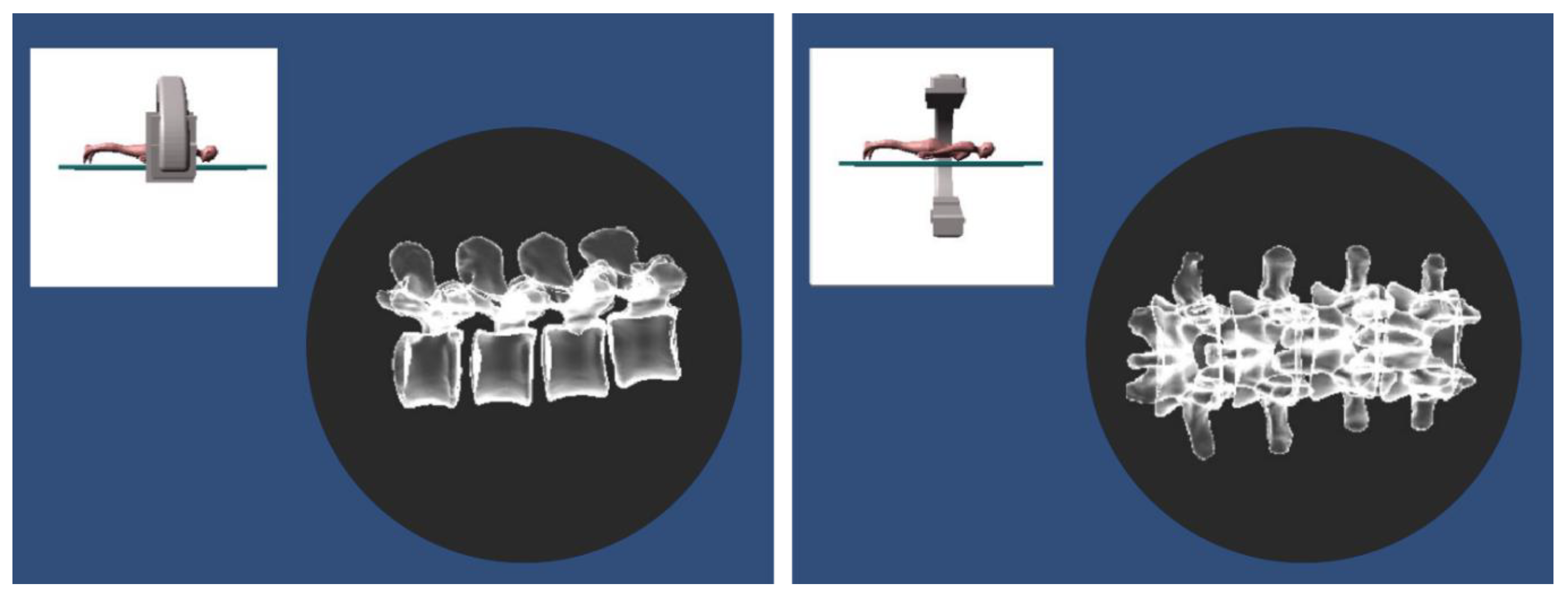
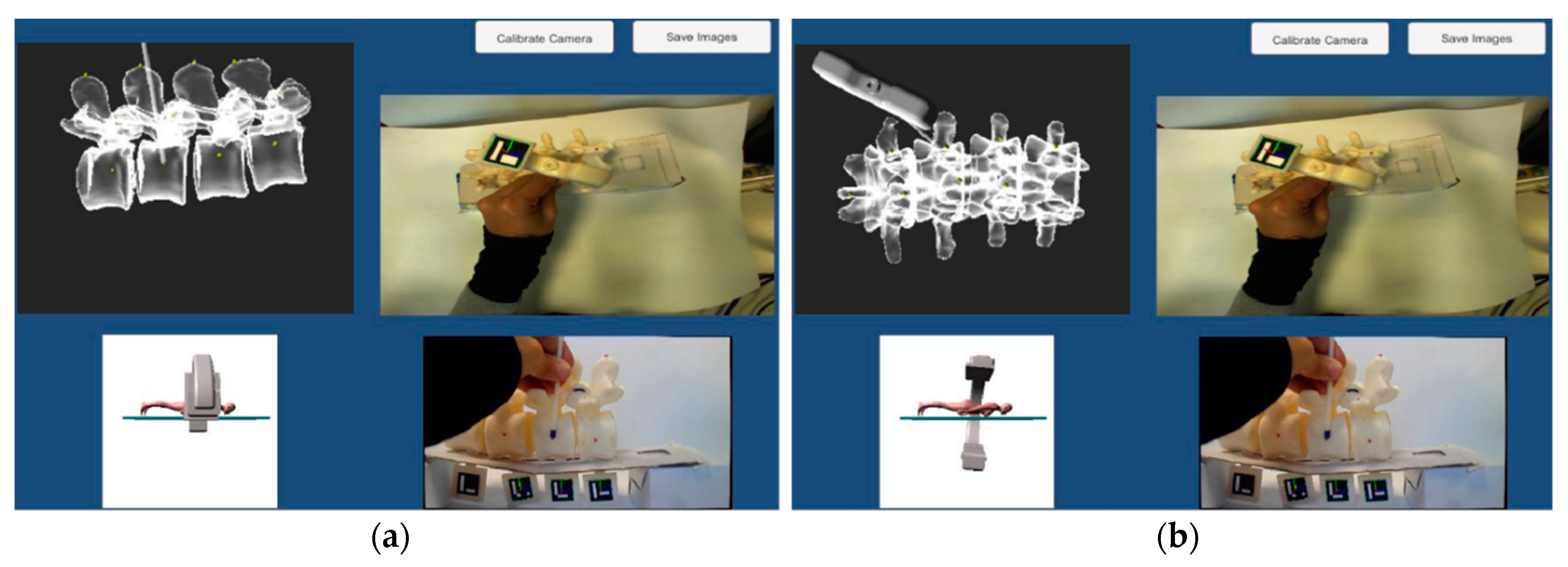
  • A “Virtual X-Ray Visualization”, simulating X-ray images of the anatomy to train for the uniplanar fluoroscopic targeting of pedicles without any exposure to harmful radiation.
  • An “AR Visualization”, allowing the observation of the torso with overlaid virtual content to assist in the implantation of the screws at the proper anatomical targets (vertebral peduncles).
Fluoroscopic images simulation has been previously proposed by Bott et al. in [21] to improve the effectiveness of C-arm training for orthopedic and reconstructive surgery. Specifically, the system designed by Bott et al. can generate digitally reconstructed radiographs based on the relative position of a real C-arm and a mannequin representing the patient: a virtual camera is used to simulate the X-ray detector, providing views of a CT volume (selected from a database containing surgical cases) from various perspectives. The mannequin is not patient-specific, and it does not contain a replica of the bony structures corresponding to the CT dataset. Moreover, the trainee can only interact with the mannequin to simulate different positioning of the patient on the surgical bed, without using any surgical instruments.
In this work, the patient specific physical bone replica and virtual information are consistent with each other, the trainee can interact with the spinal anatomy by using real surgical instrumentations, and the simulated fluoroscopic images are updated according to the current pose of the orthopedic tools and the positioning of each single vertebra.

2. Materials and Methods

This section describes both the design and development of the simulator hardware and software components (in Section 2.1 and Section 2.2), and its qualitative testing (in Section 2.3).

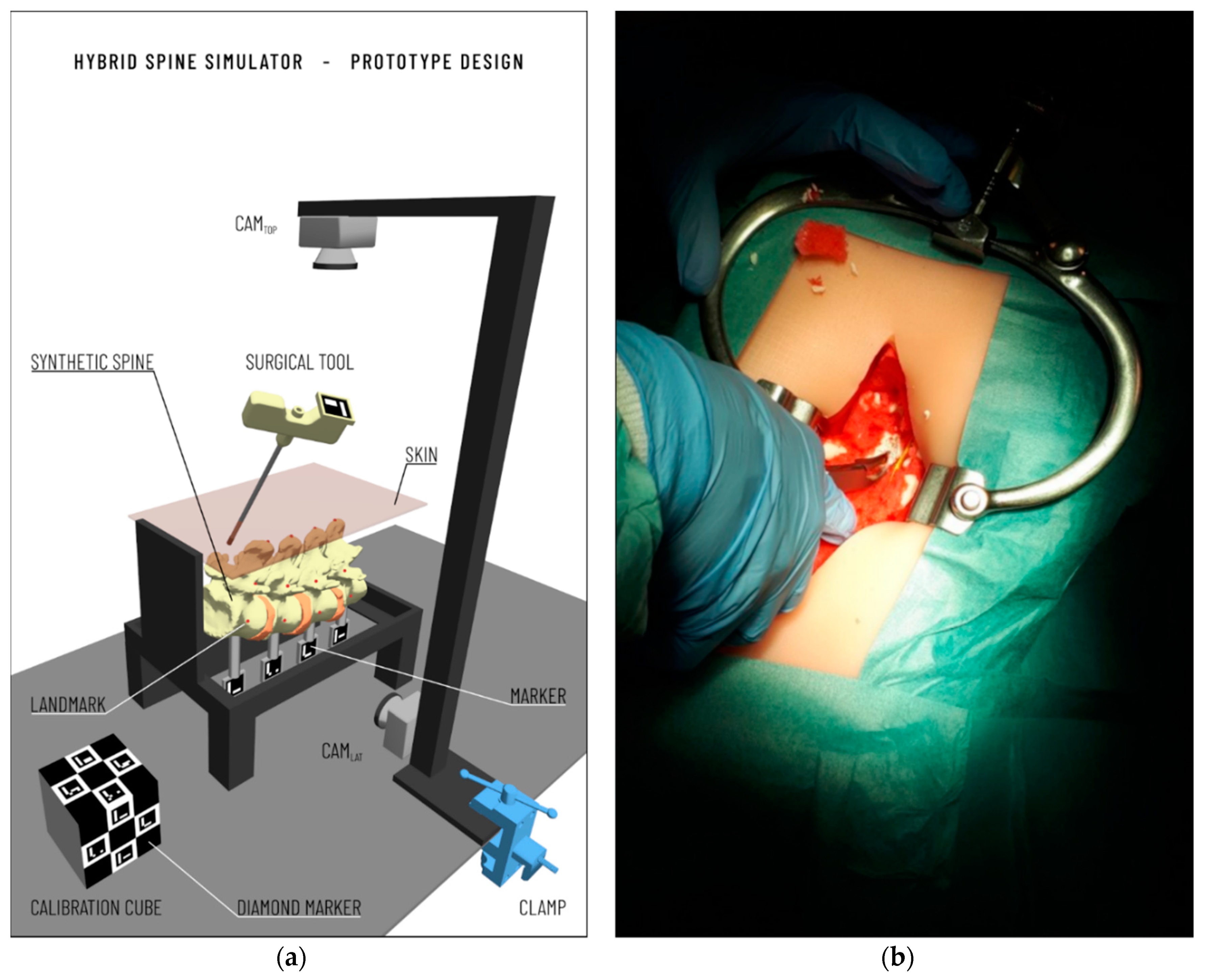
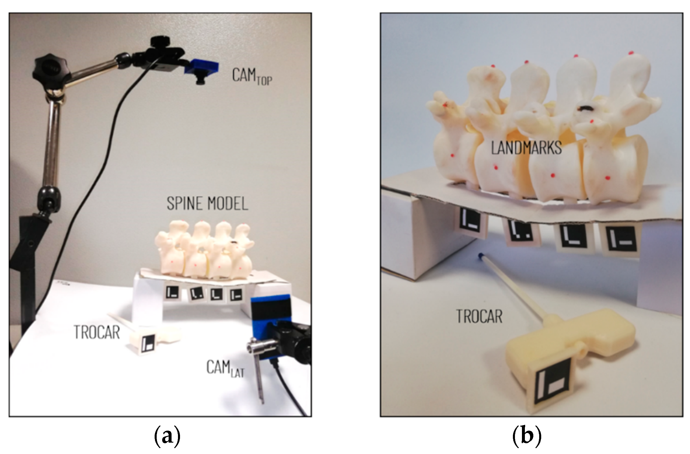
2.1. Hardware Components

The hardware components of the simulator include (Figure 1a): the spine phantom, the surgical instruments, the camera and markers for tracking, a calibration cube, as well as a desktop computer.
The spine phantom contains patient-specific vertebral synthetic models, generated by processing CT datasets, and manufactured with a fused deposition modeling (FDM) 3D printer (Dimension Elite 3D Printer Stratasys Ltd., Minneapolis, MN, USA and Rehovot, Israel). The CT datasets are processed using a semi-automatic tool, the “EndoCAS Segmentation Pipeline” integrated in the ITK-SNAP 1.5 open-source software [22], to generate the 3D virtual meshes of the patient vertebrae. Then, following the image segmentation, these 3D meshes are refined into printable 3D models, via the open-source software MeshLab [23] by performing a few optimization stages (e.g., removal of non-manifold edges and vertices, holes filling, and finally mesh filtering).
Acrylonitrile butadiene styrene (ABS) is used to manufacture vertebral models via 3D printing: this material is commonly employed for 3D printing in the orthopedic domain to replicate the bone mechanical behavior [24]. Mockups of intersomatic disks are manufactured with a soft room-temperature-vulcanizing silicone (RTV silicone), modeled to replicate the size and to maintain a mobility similar to the in-vivo human spine [25]. The spine mannequin is embedded in a soft synthetic polyurethane foam to simulate paravertebral soft tissues, and a skin-like covering made of RTV silicone is added to allow an accurate simulation of palpation and surgical incision (Figure 1b).
Vertebrae tracking is necessary to update the Virtual X-Ray Visualization and the AR Visualization accordingly to any vertebral displacement during the simulated surgical intervention. The selected tracking strategy is based on the using of low-cost cameras to reduce the total cost of the simulator. Cameras and markers’ positioning are chosen considering both technical requirements and the consistency with a real surgical scenario. ArUco markers [24], square (2 cm × 2 cm) fiducial markers composed of a binary matrix (white and black) and a black border, are used for real-time tracking of anatomical models and instrumentation.
Ad-hoc supports are designed to apply these planar fiducial markers on each vertebra, allowing us to determine their real-time pose during the entire surgical simulation. Given that the intervention is commonly performed with a posterior access, vertebral supports are designed to emerge from the bottom side of the phantom (Figure 2a), so that they are visible by a lateral camera (CamLat) which is used to track in real-time the pose of vertebrae. An additional top camera (CamTop), opportunely calibrated with CamLat, is placed above the phantom to acquire posterior images and then to offer AR views of the simulated torso, to help the trainee in the identification of pedicles and implantation of screws (e.g., vertebra models or virtual targets showing the ideal trajectory for screw insertion). At the same time, this second camera (CamTop) offers an additional point of view to track the surgical instruments (e.g., pedicle access tool equipped with a trackable fiducial marker), when they are not visible for the CamLat camera. The calibration between the reference systems of CamLat and CamTop is performed as described in Section 2.2.2 thanks to the calibration cube.
The cameras selected for the implementation of our application are the UI-164xLE camera from IDS Imaging with a 1/3” CMOS color sensor (resolution 1280 × 1024 pixels). The UI-164xLE is a compact USB camera with an S-mount adapter allowing the use of small low-cost lenses, and it allows the user to set focus manually.

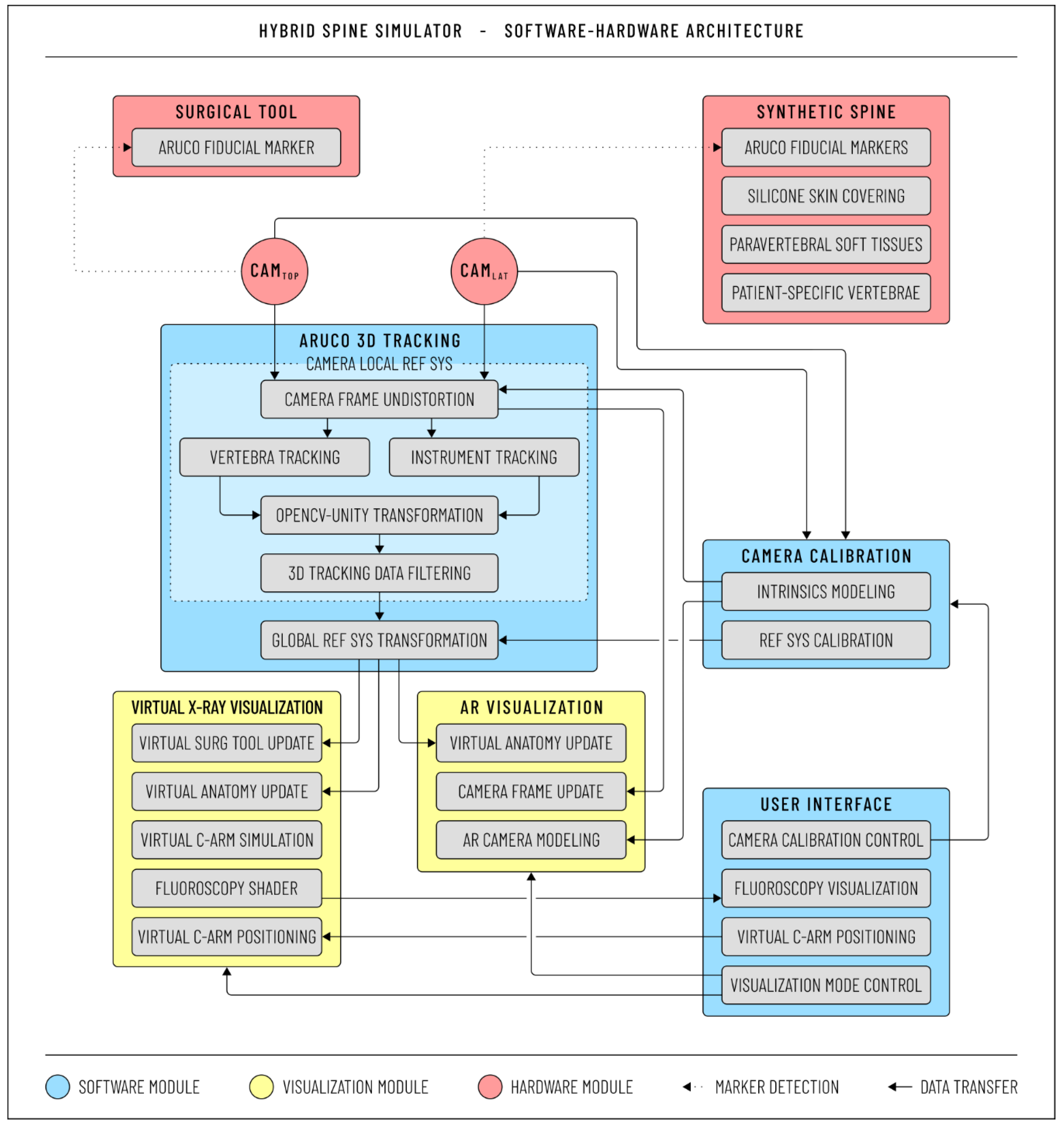
2.2. Software Architecture

In addition to the hardware components described in the previous paragraph, the architecture of the simulator (represented in Figure 3) also comprises software components. The latter have been developed using the Unity game engine [26], with OpenCV plugin for Unity [27] to perform the video-based tracking necessary for the rendering in both the AR Visualization and Virtual X-Ray Visualization.
As summarized in Figure 3, the software architecture includes the following modules: ArUco 3D Tracking, Camera Calibration, Virtual X-Ray Visualization, AR Visualization, and User Interface. The ArUco 3D Tracking module acquires images from the two cameras and receives input parameters from the Camera Calibration module to model the projection matrix of the two cameras. It runs image-processing steps allowing the Virtual X-Ray Visualization module, and the AR Visualization module to, respectively, perform the proper graphics rendering of the surgical scenario. Finally, the User Interface module allows the user to load the cameras’ intrinsics and to control both the visualization modules. Each software module is described in detail in the following sections.

2.2.1. ArUco 3D Tracking

The ArUco library [28,29], a popular library for detection of square fiducial marker based on OpenCV, is used for tracking purposes. ArUco marker tracking is based on image segmentation to extract the marker region, contour extraction to extract the polygons in the interior of the marker images, identification of marker codes by the pre-defined dictionary, and finally marker pose computation with the Levenberg–Marguardt algorithm [30].
The OpenCV undistort function is used to transform images acquired by the two cameras (CamLat and CamTop) to compensate for lens distortion (mainly radial) according to the distortion coefficients stored by the Camera Calibration module. Undistorted images are then processed by the ArUco 3D Tracking module to determine the pose of each vertebra and the surgical instrumentation.
The ArUco tracking expresses the pose of each marker according to the right-handed reference system of OpenCV, whereas Unity uses a left-handed convention (the Y-axis is inverted as shown in Figure 4): thus, a change-of-basis transformation is applied to transform the acquired tracking data from OpenCV convention to Unity convention.
A moving average filter is then applied to denoise marker tracking: the number of points in the average was empirically set to five to stabilize the marker pose with an acceptable delay for real-time monitoring. Finally, a calibration procedure is performed: indeed, the pose of markers on vertebra replicas and the pose of instrumentations are, respectively, acquired in the CamLat and CamTop local reference system and they should be expressed in the same global coordinate system. In this work, the global reference system corresponds to CamTop local reference systems (see Figure 2). The roto-translation matrix between the two reference systems is computed by the Camera Calibration module as described in the following paragraph.

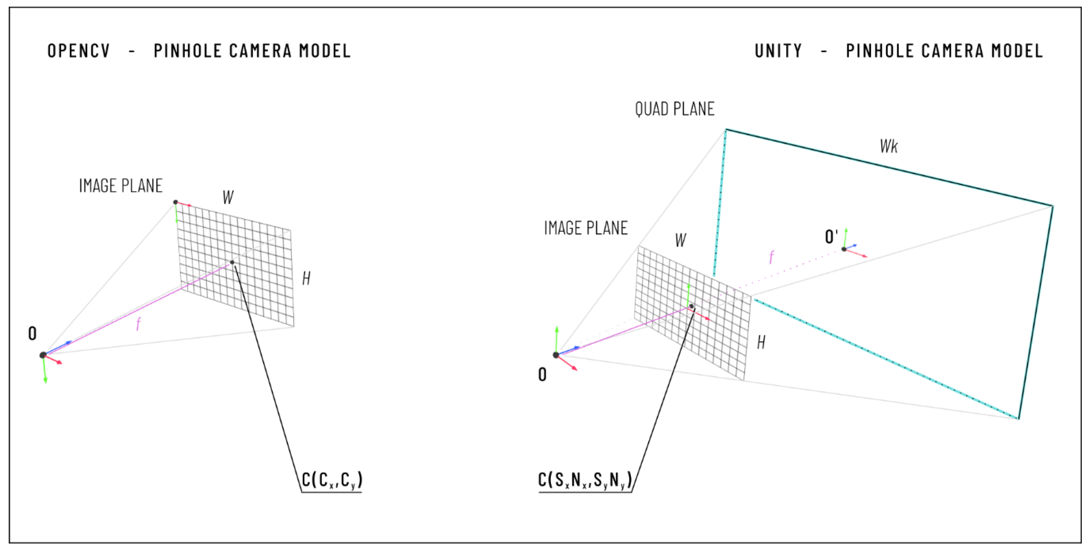
2.2.2. Camera Calibration

Cameras are modeled with the well-known pinhole camera model. Figure 4 depicts the camera coordinate frame and image coordinate frame of the pinhole camera model in OpenCV and in Unity.
An asymmetric checkerboard is used to estimate cameras’ intrinsic parameters offline using the Camera Calibrator application of the MATLAB Computer Vision Toolbox™ [31] based on the Zhang method [32]. The calibration process involves the detection of the checkerboard from at least 10 different viewpoints, and it is repeated until the reprojection error is less than 0.15 pixels.
Once the calibration is completed, the results are saved in a text file (.txt format), including:
  • the horizontal and vertical focal length expressed in pixels (fx, fy);
  • the coordinates of the principal point in pixels (cx, cy);
  • two radial distortion coefficients (K1 and K2); and
  • the input image size in pixels (Nx, Ny).
The Camera Calibration module of our software acquires these data and makes them available to the ArUco 3D Tracking and the AR Visualization modules.
The Virtual X-Ray Visualization and AR Visualization modules require the pose of vertebral models and instruments to be expressed in the same reference system. With this aim, the Camera Calibration module also computes the extrinsic calibration consisting of the roto-translation matrix between the reference systems of CamLat and CamTop. This calibration is performed by acquiring the pose of a calibration cube with two ArUco diamond markers (DiamondTop and DiamondLat) placed, respectively, on two adjacent faces (Figure 2b). ArUco diamond markers are chessboards composed of 3 × 3 squares with four ArUco fiducial markers, and they can be used for accurate pose computation in all situations when the marker size is not an issue for the application. Each diamond marker is represented by an identifier and four corners: these latter corners correspond to the four chessboard corners and they are derived from the previous detection of the four ArUco markers. The coordinate system of the diamond pose is in the center of the diamond marker with the Z-axis pointing outward, as in a simple ArUco marker [33].
For this application, diamonds markers are printed in a size of 9 × 9 cm (the four ArUco markers of a diamond marker measure 2 × 2 cm each). The calibration process includes the following steps:
  • The calibration cube is positioned inside the field of view (FOV) of both cameras, and CamLat and CamTop simultaneously acquire the diamond markers.
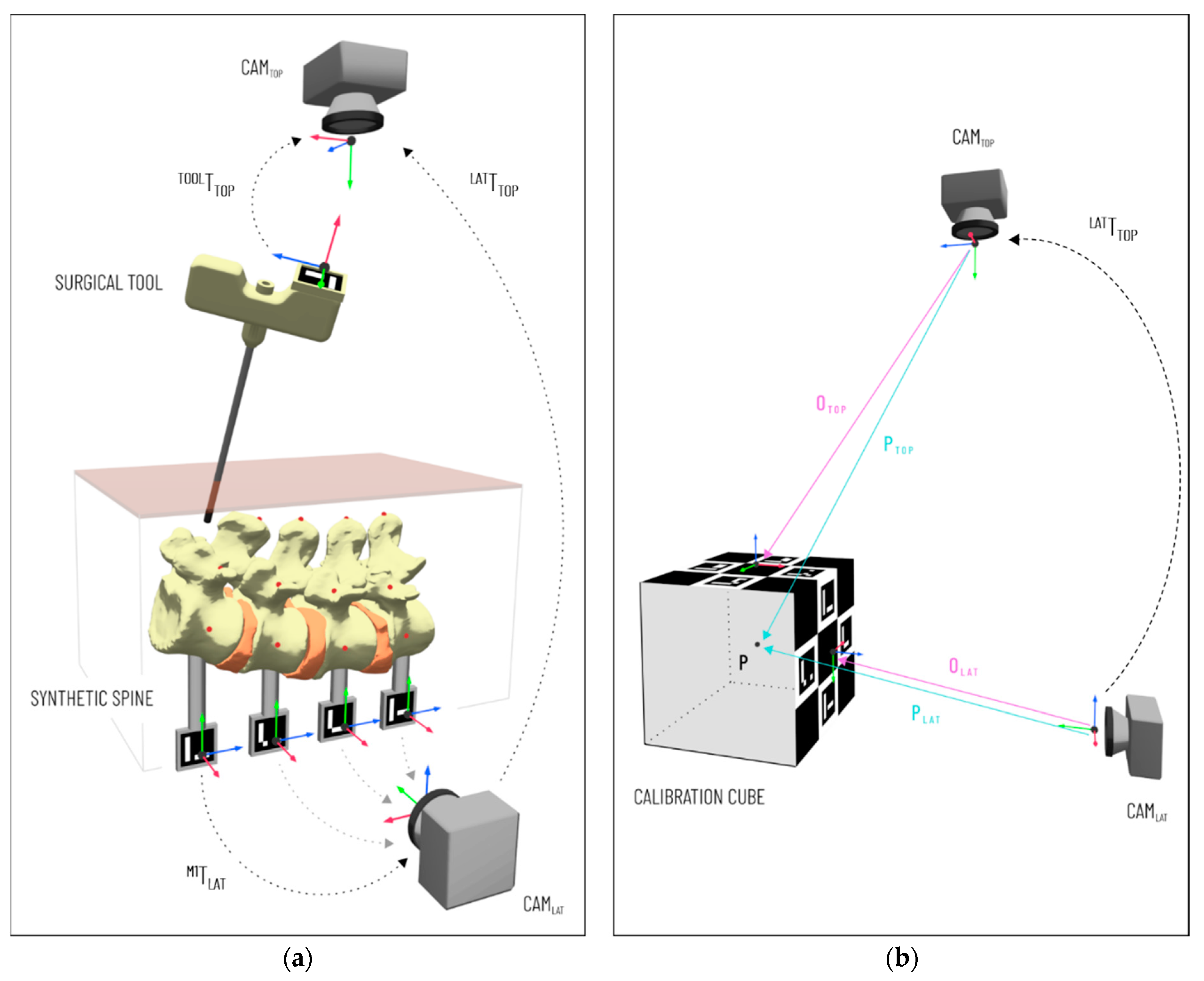
  • ArUco libraries are used to estimate the pose of each diamond marker in the reference system of the corresponding tracking camera. We refer to the position vector from the CamTop reference system to the origin of the DiamondTop reference system as O Top , while we use O Lat to denote the position vector from the origin of the CamLat reference system to the origin of the reference system of the DiamondLat (see Figure 2b).
  • The position of the cube center is estimated in each camera reference system from the position of the two diamond markers ( O Top  and  O Lat ) , the orientation of their Z-axis ( z ^ Top ,   z ^ Lat ) expressed in the tracking camera reference system, and the size (l) of the ArUco Diamond marker according to Equations (1) and (2).
    P Top = O Top + l 2 z ^ Top
    P Lat = O Lat + l 2 z ^ Lat
    where P Top is the position vector from the origin of the CamTop reference system to the calibration cube center, and P Lat is the position vector from the origin of the CamLat reference system to the calibration cube center.
  • Steps 1–2–3 are repeated at least three times moving the cube in the camera FOV to collect two clouds of n-positions (n ≥ 3).
  • A rigid point cloud registration algorithm based on singular value decomposition (SVD) is used to calculate the transformation matrix (TopTLat in Figure 2b) between the reference systems of the two cameras from the collected clouds of positions (n-positions of the center of the calibration cube expressed in the reference systems of the two cameras).

2.2.3. AR Visualization

The visualization of the AR scene requires configuration of the virtual camera using the intrinsic parameters of the corresponding real camera to obtain the same projection model and thus to guarantee the virtual–real matching. To do this in Unity, we used the “Physical Camera” component that can simulate real-world camera attributes: focal length, sensor size, and lens shift.
The lens shift (Sx, Sy) of a Physical Camera in Unity is a dimensionless value which “offsets the camera’s lens from its sensor horizontally and vertically” [34] and it can be used to model the principal point offset. This lens shift is relative to the sensor size, and it is derived from the principal point coordinates expressed in pixels (cx, cy) and the input image size in pixels (Nx, Ny), according to Equations (3) and (4).
S x   = c x   N x   2 N x  
S y   = c y   N y   2 N y  
A quad primitive is used to render the images acquired by the camera after undistortion. The quad size is set as a multiple of the sensor size (W, H) and its position O is determined as in Equation (5), where k is the ratio between the quad size and the sensor size.
O = ( S x   N x   k S y   N y   k f k )

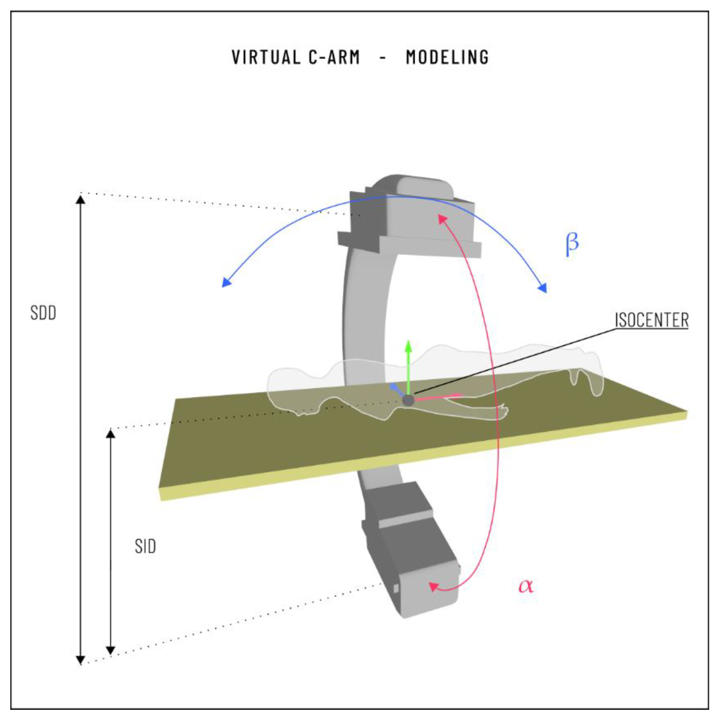
2.2.4. Virtual X-ray Visualization

This module generates realistic virtual fluoroscopic images of the current surgical scene that comprises: the surgical tool, the patient-specific vertebrae, a virtual human body, and a C-arm 3D model (the “Virtual C-Arm”). The pose of the vertebrae and the tool are expressed in the same reference system thanks to the Camera Calibration module. The human body (a standard 3D model, with size compatible with the patient-specific virtual spine) is manually registered according to the anatomical correct positioning of the spine The Virtual C-Arm is scaled to a realistic size (the source-to-detector distance, SDD, is 0.120 m as in [35]), and a “virtual isocenter” is placed at a distance of 0.64 m from the source (source-to-isocenter distance, SID, of 0.64 m).
X-ray simulation is obtained through the implementation of a virtual camera (the “X-ray Camera”), positioned at the Virtual C-Arm source. The FOV of the X-ray Camera and its clipping planes are manually tuned according to the size of the Virtual C-Arm.
The X-ray beam projection of a C-arm device is commonly defined using two rotation angles (Figure 5): the left/right anterior oblique (LAO/RAO) angle, α; and the caudal/cranial (CAUD/CRAN) angle, β (in the literature, these are also referred to as the angular and orbital rotation angles, respectively) [36]. A custom Unity script-component was implemented to allow the user to rotate the Virtual C-Arm around its isocenter, adjusting α and β values with keyboard inputs to obtain different image projections. Moreover, this script also implements the Virtual C-Arm translation along the three main axes.
The X-ray Camera uses a custom replacement shader to render the vertebral meshes and the tracked instrumentation: the “X-ray effect” is implemented with a colored, semi-transparent shader, with no backface culling to also render polygons that are facing away from the viewer (Figure 6).

2.2.5. User Interface

The User Interface allows the user to load the cameras’ intrinsics, to control the Virtual C-Arm, and to visualize the generated images. Moreover, the user can switch between the calibration (Figure 7a) and the simulation application. During the simulation, the user can turn on both the AR Visualization and the Virtual X-ray Visualization modalities at the same time (Figure 7b), or activate the Virtual X-ray Visualization alone (Figure 6). The Virtual X-ray Visualization allows the visualization of the Virtual C-Arm pose and the corresponding simulated fluoroscopic image. The user can move the Virtual C-Arm (by adjusting the angular and orbital rotation angles and translating the Virtual C-Arm with respect to the patient bed) via keyboard input.

2.3. Simulator Testing

Quantitative tests were performed to evaluate the accuracy of both the AR Visualization (that in turn gives information about the calibration of the two cameras), and the Virtual X-Ray Visualization. Figure 8 illustrates the testing setup: the two cameras are held in position by an articulated arm, and the vertebral models are assembled and inserted into a support structure.

2.3.1. Evaluation of the Camera Calibration and AR Visualization

Three fiducial spherical landmarks (2 mm in diameter) were added to each vertebra model at known positions to evaluate the cameras’ calibration: one was positioned at the vertebral body so that it is visible by the lateral camera (CamLat), and the other two at the vertebral peduncle and the spinous process so that are visible by the top camera, CamTop (Figure 8).
The VR models of landmarks were added to the AR scene for estimating the target visualization error (TVE), thus evaluating the accuracy of the AR overlay (a similar procedure was adopted in [16] to evaluate the accuracy of a hybrid simulator). With this aim, the vertebral models were moved in ten different positions, acquiring each time the AR image of both virtual cameras.
More specifically, for each position, two images were captured from each virtual camera. The first image was acquired with AR switched-off; therefore, this image contains only the scene as viewed by the camera, without AR information. The second image was acquired with AR switched-on, thus it also shows the virtual landmarks. This produced for each camera two sets of corresponding images: we refer to the set with AR switched-off as the “Real Set”, and to the set with AR switched-on as the “AR Set”. The correspondence between the Real Set and the AR Set guarantees an accurate modeling of the camera projection models and their intrinsic and extrinsic calibration, which is a requirement for the realism and fidelity of both the AR Visualization and the Virtual X-ray Visualization modalities.
The acquired sets were automatically processed to estimate the 2D target visualization error (TVE2D), that is: the offset, expressed in pixels, between the virtual and real objects in the image plane (i.e., the centroids of the virtual landmarks, and the corresponding real 3D-printed landmarks). The Real Set and the AR Set were processed in the hue–saturation-value (HSV) color space that allows a robust segmentation even when the target objects show non-uniformities in illumination, shadows, or shading [37]. The image processing, performed in MATLAB, included the following steps:
  • Transformation from RGB to HSV color space.
  • Detection of the virtual landmarks in the AR Set (Figure 9a).
  • Detection of the 3D-printed landmarks in the Real Set (Figure 9b).
Virtual landmarks were detected with the circular Hough transform, using their diameter as an input parameter. The Hough transform sensitivity was adjusted to detect all the landmarks in the image (four markers for CamLat and eight for CamTop): an increase in the sensitivity allows the detection of more circular objects, including weak and partially obscured circles (however higher sensitivity values also increase the risk of false detection) [38].
The knowledge of the virtual markers position derived from step 2 was used to improve the robustness of step 3. Each 3D-printed landmark indeed was searched within a region of interest (ROI) centered on the position of the corresponding virtual landmark. The ROI was segmented to identify the red areas through filtering on the hue (H) and saturation (S) channels.
Detected 2D positions were used to calculate the TVE2D, and subsequently to derive the TVE3D, a rough estimation of the visualization error in space at a fixed distance, expressed in mm [39]. The TVE3D was estimated by inverting the projection equation as in Equation (6).
T V E 3 D   = T V E 2 D   k   Z c   f
In Equation (6): ZC is the estimated working distance, f is the camera focal length estimated in the calibration stage, and k is the scaling factor of the image sensor (number of pixels per unit of length).

2.3.2. Evaluation of the Total Error

Inaccurate tracking of surgical instrumentation is a source of error that can affect the realism and fidelity of the system, particularly of the Virtual X-ray Visualization that simultaneously shows the tracked vertebra and instruments. For this reason, we performed additional tests, using a mockup of a Jamshidi trocar (a tool for percutaneous pedicle cannulation) equipped with an ArUco marker (Figure 9) to estimate the total error. We pointed the trocar tip at the vertebra landmarks under direct visual control, and we calculated the accuracy as the distance between the tracked tip position and the virtual landmark. Targeting landmarks under direct visualization allowed us to minimize positioning inaccuracy due to the experience level of the experimenter, compared to targeting under Virtual X-ray Visualization.
The error was calculated as the projection of the Euclidean distance on the XZ- and XY- planes that coincide with the simulated anteroposterior and latero–lateral fluoroscope projections, respectively.

3. Results

The target visualization errors (both TVE2D and TVE3D) were estimated for each spine pose for a total of: 40 measurements for the lateral camera, CamLat (4 markers detected in each of the 10 images); and 80 measurements for the top camera, CamTop (8 markers detected in each of the 10 images). Table 1 summarizes mean (µ) and standard deviation (σ) values for each of the 10 images.
The total error was calculated for each vertebra (for a single spine pose), three times for each of the landmarks (landmarks on the vertebral body, pedicle and spinous process) for a total of 36 measurements. Table 2 summarizes mean (µ) and standard deviation (σ) values for each vertebra.
The obtained TVE3D and targeting errors confirm the feasibility of the proposed strategy to track the vertebral models/surgical tools, and to coherently visualize them both in AR Visualization mode and in Virtual X-ray Visualization as an aid for the training of pedicle screw implantation in lumbar vertebrae. The errors are indeed lower than half the size of lumbar pedicle radius which, according to [40], is 6.4–6.5 mm for L1 (left and right pedicle, respectively) increases from L1 to L4, and increased sharply at L5 reaching a mean size of 17.5–17.7 mm (left and right pedicle, respectively).
The TVE3D of the CamTop is an estimation of the error in the registration of vertebral models in the global (CamTop) reference systems (Vertebra Registration Error). As for the targeting error we should consider the following sources of error: Vertebra Registration Error, error in the localization of the ArUco marker used to track the surgical tool in the global (CamTop) reference system, inaccuracy of the users in the alignment of the tool tip with the marker, and finally the error in the tool calibration.
The instrument calibration is required to infer the pose of the tool tip from the pose of the detected marker. In this study, we used a built-in marker to track the trocar mockup and we derived the calibration matrix from the CAD (computer-aided design) project; a procedure such as the pivot calibration [41] can be used instead for localizing a real surgical tool using a marker whose relative pose with the respect to the tool tip is unknown a priori. Given the obtained TVE3D and targeting error we can assume that, even using a real surgical tool, the final accuracy of the system would be enough for the proposed application (screw implantation in lumbar vertebrae).
Figure 10 illustrates the simulated lateral (Figure 10a) and anterior–posterior (Figure 10b) fluoroscopic view of the spine during the targeting of one marker with the Jamshidi trocar mockup. The corresponding actual positioning of the trocar is shown by the images captured by the lateral (CamLat) and the top camera (CamTop). For these experiments, the “X-ray” shader was applied only to the vertebral models while a standard opaque material was used for the landmarks and the instrument model for a better visualization of their pose.

4. Discussion and Conclusions

A recent literature review on orthopedic surgery simulation highlights the need for “high-tech” multimodal simulators allowing the trainees to develop visuospatial awareness of the anatomy and a “sense of touch” for surgical procedures. Starting from these considerations, in a previous study we have presented a hybrid simulator for open orthopedic surgery using the Microsoft HoloLens [14]. Although HDMs represent an ideal solution to develop an immersive training environment for open surgery, other non-wearable AR-enabling devices deserve consideration to develop hybrid simulators for training of image-guided surgical procedures such as spinal fluoroscopic guided interventions. For this reason, in this work we present and technically test a prototype of an innovative hybrid spine simulator for pedicle screws fixation, based on the use of a traditional stand-up display, that is consistent with the equipment of a real surgical scenario and thus appears the best technological choice in terms of realism.
The proposed strategy to build the spine simulator takes advantage of:
  • patient-specific modeling to improve the realism of the simulated surgical pathology;
  • rapid prototyping for the manufacturing of synthetic vertebral models;
  • AR to enrich the simulated surgical scenario and help the learner to carry out the procedure;
  • VR functionalities for simulating X-ray images of the anatomy to train for the uniplanar fluoroscopic targeting of pedicles without any exposure to harmful radiations.
Fiducial markers are used to track in real-time the position of each vertebra (which can move relative to adjacent vertebrae to simulate the mobility of the human spine) and surgical instrumentation. Two calibrated cameras, arranged in an orthogonal configuration, are proposed to track the vertebral models (lateral camera) and to track the instrumentation and produce an AR view of the simulated torso (top camera). A simulated virtual C-arm is used to generate synthetic fluoroscopic projections, using a simple approach based on shader programming to achieve an “X-ray effect”.
Quantitative tests show that the proposed low-cost tracking approach is accurate enough for training in pedicle screws insertion in lumbar vertebrae.
Future studies will improve the robustness of the simulator, involving clinicians to test the system and define the best positioning of the cameras (an ad-hoc support structure will be designed to hold in position the two cameras), fiducial markers, and lights so that the accuracy is maximized and, at the same time, the tracking set-up (camera, markers and lights) does not hinder the surgeon’s movements and manipulation of the instruments. To this end, the proposed tracking strategy that is based on the optical tracking of the passive markers, is advantageous compared to other techniques using wired sensors (e.g., electromagnetic sensors). On the other hand, the selected tracking approach can fail due to marker occlusions: in our simulator, this is particularly true for the markers placed on the instruments. However, for our application, continuous instrument tracking is not necessary because, even in the real surgical workflow, fluoroscopic imaging is not continuous but intermittent to minimize the radiation dose to the patient.
In the future, Face Validity, Content Validity, and Construct Validity tests will be performed for a complete assessment of the proposed simulator for training in pedicle screws insertion.

Author Contributions

Conceptualization, S.C., G.T.; methodology, S.C., G.T., V.F. and P.D.P.; software, S.C.; validation, S.C., V.M.; formal analysis, S.C. and V.M.; investigation, S.C.; resources, V.F.; data curation, S.C. and V.M.; writing—original draft preparation, S.C., G.T. and V.M.; writing—review and editing, G.T., P.D.P. and V.F.; visualization, V.F.; project administration, S.C.; funding acquisition, V.F. All authors have read and agreed to the published version of the manuscript.

Funding

This research was partially funded by the CRIO2AR project, Fas Salute 2018—Regione Toscana. This work was also supported by the Italian Ministry of Education and Research (MIUR) in the framework of the CrossLab project (Departments of Excellence) of the University of Pisa, Laboratory of Augmented Reality.

Institutional Review Board Statement

Not applicable.

Informed Consent Statement

Not applicable.

Data Availability Statement

The data presented in this study are available on request from the corresponding author. The data are not publicly available due to its proprietary nature.

Conflicts of Interest

The authors declare no conflict of interest.

References

  1. Atesok, K.; Hurwitz, S.; Anderson, D.D.; Satava, R.; Thomas, G.W.; Tufescu, T.; Heffernan, M.J.; Papavassiliou, E.; Theiss, S.; Marsh, J.L. Advancing Simulation-Based Orthopaedic Surgical Skills Training: An Analysis of the Challenges to Implementation. Adv. Orthop. 2019, 2019, 2586034. [Google Scholar] [CrossRef] [Green Version]
  2. Parchi, P.; Evangelisti, G.; Cervi, V.; Andreani, L.; Carbone, M.; Condino, S.; Ferrari, V.; Lisanti, M. Patient’s Specific Template for Spine Surgery. In Computer-Assisted Musculoskeletal Surgery; Ritacco, L.E., Milano, F.E., Chao, E., Eds.; Springer International Publishing: Berlin/Heidelberg, Germany, 2016. [Google Scholar] [CrossRef]
  3. Ferrari, V.; Parchi, P.; Condino, S.; Carbone, M.; Baluganti, A.; Ferrari, M.; Mosca, F.; Lisanti, M. An optimal design for patient-specific templates for pedicle spine screws placement. Int. J. Med. Robot. Comput. Assist. Surg. 2013, 9, 298–304. [Google Scholar] [CrossRef]
  4. Kotsis, S.V.; Chung, K.C. Application of the “see one, do one, teach one” concept in surgical training. Plast. Reconstr. Surg. 2013, 131, 1194–1201. [Google Scholar] [CrossRef] [Green Version]
  5. Stirling, E.R.; Lewis, T.L.; Ferran, N.A. Surgical skills simulation in trauma and orthopaedic training. J. Orthop. Surg. Res. 2014, 9, 126. [Google Scholar] [CrossRef] [PubMed] [Green Version]
  6. Yiasemidou, M.; Gkaragkani, E.; Glassman, D.; Biyani, C.S. Cadaveric simulation: A review of reviews. Ir. J. Med. Sci. 2018, 187, 827–833. [Google Scholar] [CrossRef] [PubMed] [Green Version]
  7. Parchi, P.; Condino, S.; Carbone, M.; Gesi, M.; Ferrari, V.; Ferrari, M.; Lisanti, M. Total hip replacement simulators with virtual planning and physical replica for surgical training and reharsal. In Proceedings of the 12th IASTED International Conference on Biomedical Engineering, BioMed, Innsbruck, Austria, 15–17 February 2016; pp. 97–101. [Google Scholar]
  8. Anderson, P.A. Chapter 6—3D Printing for Education and Surgical Planning in Orthopedic Surgery. In 3D Printing in Orthopaedic Surgery; Dipaola, M., Wodajo, F.M., Eds.; Elsevier: Amsterdam, The Netherlands, 2019; pp. 55–63. [Google Scholar] [CrossRef]
  9. Park, H.J.; Wang, C.; Choi, K.H.; Kim, N. Use of a life-size three-dimensional-printed spine model for pedicle screw instrumentation training. J. Orthop. Surg. Res. 2018, 13, 1–8. [Google Scholar] [CrossRef] [PubMed]
  10. Vaughan, N.; Dubey, V.N.; Wainwright, T.W.; Middleton, R.G. A review of virtual reality based training simulators for orthopaedic surgery. Med. Eng. Phys. 2016, 38, 59–71. [Google Scholar] [CrossRef] [PubMed] [Green Version]
  11. Pfandler, M.; Lazarovici, M.; Stefan, P.; Wucherer, P.; Weigl, M. Virtual reality-based simulators for spine surgery: A systematic review. Spine J. 2017, 17, 1352–1363. [Google Scholar] [CrossRef] [PubMed]
  12. Immersive Touch Surgical Simulation Suite for Spine Surgery. Available online: https://www.immersivetouch.com/ivsp-for-spine-surgery (accessed on 11 December 2020).
  13. Gasco, J.; Patel, A.; Ortega-Barnett, J.; Branch, D.; Desai, S.; Kuo, Y.F.; Luciano, C.; Rizzi, S.; Kania, P.; Matuyauskas, M.; et al. Virtual reality spine surgery simulation: An empirical study of its usefulness. Neurol. Res. 2014, 36, 968–973. [Google Scholar] [CrossRef]
  14. Condino, S.; Turini, G.; Parchi, P.D.; Viglialoro, R.M.; Piolanti, N.; Gesi, M.; Ferrari, M.; Ferrari, V. How to Build a Patient-Specific Hybrid Simulator for Orthopaedic Open Surgery: Benefits and Limits of Mixed-Reality Using the Microsoft HoloLens. J. Healthc. Eng. 2018, 2018. [Google Scholar] [CrossRef] [PubMed]
  15. Viglialoro, R.M.; Condino, S.; Gesi, M.; Ferrari, M.; Ferrari, V. Augmented reality simulator for laparoscopic cholecystectomy training. In Lecture Notes in Computer Science (Including Subseries Lecture Notes in Artificial Intelligence and Lecture Notes in Bioinformatics); Springer: Cham, Switzerland, 2014; Volume 8853, pp. 428–433. [Google Scholar]
  16. Viglialoro, R.M.; Esposito, N.; Condino, S.; Cutolo, F.; Guadagni, S.; Gesi, M.; Ferrari, M.; Ferrari, V. Augmented Reality to Improve Surgical Simulation: Lessons Learned Towards the Design of a Hybrid Laparoscopic Simulator for Cholecystectomy. IEEE Trans. Biomed. Eng. 2019, 66, 2091–2104. [Google Scholar] [CrossRef] [PubMed]
  17. Microsoft HoloLens (1st Gen). Available online: https://docs.microsoft.com/en-us/hololens/hololens1-hardware (accessed on 12 January 2021).
  18. Condino, S.; Carbone, M.; Piazza, R.; Ferrari, M.; Ferrari, V. Perceptual Limits of Optical See-Through Visors for Augmented Reality Guidance of Manual Tasks. IEEE Trans. BioMed Eng. 2019. [Google Scholar] [CrossRef] [PubMed]
  19. Kim, J.; Kane, D.; Banks, M.S. The rate of change of vergence–accommodation conflict affects visual discomfort. Vis. Res. 2014, 105, 159–165. [Google Scholar] [CrossRef] [PubMed] [Green Version]
  20. Kim, E.; Shin, G. Head Rotation and Muscle Activity When Conducting Document Editing Tasks with a Head-Mounted Display. Proc. Hum. Factors Ergon. Soc. Annu. Meet. 2018, 62, 952–955. [Google Scholar] [CrossRef]
  21. Bott, O.; Dresing, K.; Wagner, M.; Raab, B.-W.; Teistler, M. Use of a C-Arm Fluoroscopy Simulator to Support Training in Intraoperative Radiography. Radiographics 2011, 31, E65–E75. [Google Scholar] [CrossRef]
  22. Yushkevich, P.A.; Piven, J.; Hazlett, H.C.; Smith, R.G.; Ho, S.; Gee, J.C.; Gerig, G. User-guided 3D active contour segmentation of anatomical structures: Significantly improved efficiency and reliability. NeuroImage 2006, 31, 1116–1128. [Google Scholar] [CrossRef] [Green Version]
  23. Cignoni, P.; Callieri, M.; Corsini, M.; Dellepiane, M.; Ganovelli, F.; Ranzuglia, G. MeshLab: An Open-Source Mesh Processing Tool. In Proceedings of the Eurographics Italian Chapter Conference, Salerno, Italy, 2–4 July 2008; Volume 1, pp. 129–136. [Google Scholar]
  24. Parchi, P.D.; Ferrari, V.; Piolanti, N.; Andreani, L.; Condino, S.; Evangelisti, G.; Lisanti, M. Computer tomography prototyping and virtual procedure simulation in difficult cases of hip replacement surgery. Surg. Technol. Int. 2013, 23, 228–234. [Google Scholar]
  25. Parchi, P.; Carbone, M.; Condino, S.; Stagnari, S.; Rocchi, D.; Colangeli, S.; Ferrari, M.; Scaglione, M.; Ferrari, V. Patients Specific Spine Simulators for Surgical Training and Rehearsal in Pedicule Screws Placement: A New Way for Surgical Education. In Proceedings of the CAOS 2020. The 20th Annual Meeting of the International Society for Computer Assisted Orthopaedic Surgery, Brest, France, 10–13 June 2020; pp. 225–230. [Google Scholar]
  26. Unity3D. 2020. Available online: https://unity.com/ (accessed on 27 October 2020).
  27. OpenCV for Unity. Available online: https://enoxsoftware.com/opencvforunity/ (accessed on 27 October 2020).
  28. Romero-Ramirez, F.J.; Muñoz-Salinas, R.; Medina-Carnicer, R. Speeded up detection of squared fiducial markers. Image Vis. Comput. 2018, 76, 38–47. [Google Scholar] [CrossRef]
  29. Garrido-Jurado, S.; Muñoz-Salinas, R.; Madrid-Cuevas, F.; Medina-Carnicer, R. Generation of fiducial marker dictionaries using Mixed Integer Linear Programming. Pattern Recognit. 2015, 51, 481–491. [Google Scholar] [CrossRef]
  30. Kam, H.C.; Yu, Y.K.; Wong, K.H. An Improvement on ArUco Marker for Pose Tracking Using Kalman Filter. In Proceedings of the 2018 19th IEEE/ACIS International Conference on Software Engineering, Artificial Intelligence, Networking and Parallel/Distributed Computing (SNPD), Busan, Korea, 27–29 June 2018; pp. 65–69. [Google Scholar]
  31. Matlab Computer Vision Toolbox. Available online: https://www.mathworks.com/products/computer-vision.html (accessed on 29 October 2020).
  32. Zhang, Z. A flexible new technique for camera calibration. IEEE Trans. Pattern Anal. Mach. Intell. 2000, 22, 1330–1334. [Google Scholar] [CrossRef] [Green Version]
  33. OpenCV—Detection of Diamond Markers. Available online: https://docs.opencv.org/master/d5/d07/tutorial_charuco_diamond_detection.html (accessed on 15 December 2020).
  34. Unity Manual—Using Physical Cameras. Available online: https://docs.unity3d.com/Manual/PhysicalCameras.html (accessed on 11 December 2020).
  35. Daly, M.J.; Siewerdsen, J.H.; Cho, Y.B.; Jaffray, D.A.; Irish, J.C. Geometric calibration of a mobile C-arm for intraoperative cone-beam CT. Med. Phys. 2008, 35, 2124–2136. [Google Scholar] [CrossRef] [PubMed]
  36. Ritschl, L.; Kuntz, J.; Kachelrieß, M. The Rotate-Plus-Shift C-Arm Trajectory: Complete CT Data with Limited Angular Rotation; SPIE: Bellingham, WA, USA, 2015; Volume 9412. [Google Scholar]
  37. Mamone, V.; Viglialoro, R.M.; Cutolo, F.; Cavallo, F.; Guadagni, S.; Ferrari, V. Robust Laparoscopic Instruments Tracking Using Colored Strips. In Proceedings of the Augmented Reality, Virtual Reality, and Computer Graphics, Ugento, Italy, 12–15 June 2017; pp. 129–143. [Google Scholar]
  38. Yuen, H.K.; Princen, J.; Illingworth, J.; Kittler, J. Comparative study of Hough Transform methods for circle finding. Image Vis. Comput. 1990, 8, 71–77. [Google Scholar] [CrossRef] [Green Version]
  39. Ferrari, V.; Viglialoro, R.M.; Nicoli, P.; Cutolo, F.; Condino, S.; Carbone, M.; Siesto, M.; Ferrari, M. Augmented reality visualization of deformable tubular structures for surgical simulation. Int. J. Med. Robot. Comput. Assist. Surg. 2016, 12, 231–240. [Google Scholar] [CrossRef] [PubMed]
  40. Lien, S.-B.; Liou, N.-H.; Wu, S.-S. Analysis of anatomic morphometry of the pedicles and the safe zone for through-pedicle procedures in the thoracic and lumbar spine. Eur. Spine J. 2007, 16, 1215–1222. [Google Scholar] [CrossRef] [PubMed] [Green Version]
  41. Yaniv, Z. Which pivot calibration? In Medical Imaging 2015: Image-Guided Procedures, Robotic Interventions, and Modeling; SPIE: Bellingham, WA, USA, 2015. [Google Scholar] [CrossRef]
Figure 1. (a, left) Overview of the final design of the simulator hardware components: a spine phantom, equipped with markers for tracking, surgical tools with markers, two cameras for tracking, and a calibration cube. (b, right) The final appearance of the 3D printed spine embedded in the soft synthetic foam and covered with a skin-like silicone layer.
Applsci 11 01038 g001
Figure 2. (a, left) Cameras and fiducial markers setup with schematic representation of transformation matrix involved. (b, right) Calibration of the lateral and top cameras with the calibration cube.
Applsci 11 01038 g002
Figure 3. Architecture of the simulator. The Hardware module consists of two cameras, a synthetic spine, and surgical tools with ArUco fiducial markers. The simulator also includes: the Camera Calibration module to model the projection matrix of the two cameras; the ArUco calibration module to track the spine and the surgical instrumentations; the User Interface to load the cameras’ intrinsics, to control the virtual C-Arm and the visualization modules, and to visualize the generated images; the Virtual X-Ray and the augmented reality (AR) visualization module to generate and update the fluoroscopic images and the AR view.
Applsci 11 01038 g003
Figure 4. Camera coordinate frame and image coordinate frame of the pinhole camera model in OpenCV and in Unity. Both OpenCV and Unity assume that the camera principal axis is aligned with the positive Z-axis of the camera coordinate system, but the OpenCV coordinate system is right-handed (the Y-axis is oriented downward) while the Unity coordinate system is left-handed (the Y-axis is oriented upward). Moreover, in OpenCV, the origin of the image coordinate system is the center of the upper-left image pixel while in Unity the origin of the image coordinate system is at the image center. This picture also shows the coordinate system of the quad primitive used in Unity.
Applsci 11 01038 g004
Figure 5. Virtual C-Arm modeling for the Virtual X-Ray Visualization module. The Virtual C-Arm can rotate around its isocenter, adjusting α and β values with keyboard inputs to obtain different image projections.
Applsci 11 01038 g005
Figure 6. Two screenshots of the User Interface during the simulation in Virtual X-ray Visualization modality. The User Interface shows the relative positioning of the Virtual C-Arm and the patient and the corresponding simulated fluoroscopic image.
Applsci 11 01038 g006
Figure 7. Screenshots of the User Interface: (a, left) the User Interface during a calibration procedure; (b, right) the User Interface during a simulation session. This second screenshot shows both the virtual fluoroscopic image (from the selected Virtual C-Arm pose) and the AR view from the top camera (CamTop).
Applsci 11 01038 g007
Figure 8. Testing setup: (a, left) configuration of the two cameras and the spine model; (b, right) a close-up of the spine model with 3D-printed spherical landmarks, and the trocar mockup.
Applsci 11 01038 g008
Figure 9. Examples of corresponding images of AR Set and Real Set from the CamTop view. (a, left) Image from the AR Set: the eight detected digital markers are circled in red, and a zoomed view of the first top left marker is provided. (b, right) Image from the Real Set: the detected 3D-printed markers are circled in red with each region of interest (ROI) enclosed by a black-edged square, and a zoomed view of the first top left marker is provided.
Applsci 11 01038 g009
Figure 10. Two screenshots of the User Interface during the targeting of a landmark with a trocar mockup. (a, left) The pose of the Virtual C-Arm is adjusted to simulate a lateral fluoroscopic image. (b, right) The pose of the Virtual C-Arm is adjusted to simulate an anterior–posterior fluoroscopic image.
Applsci 11 01038 g010
Table 1. Mean (µ) and standard deviation (σ) of target visualization errors (TVE)2D and TVE3D values for each of the 10 poses.
Pos 1Pos 2Pos 3Pos 4Pos 5Pos 6Pos 7Pos 8Pos 9Pos 10Total
CamLatTVE2D
(pixel)
µ= 8.19.110.1106.58.87.47.55.56.68
σ= 7.77.89.99.25.59.28.48.56.16.44.1
TVE3D
(mm)
0.70.9110.60.90.80.80.60.70.8
0.30.40.40.70.30.40.30.40.30.50.4
CamTopTVE2D
(pixel)
5.96.54.94.74.56.66.63.94.16.85.5
2.83.83.23.61.23.43.22.22.23.13
TVE3D
[mm]
1.71.91.51.41.4221.11.321.6
0.81.10.91.10.4110.60.70.90.4
Table 2. Mean (µ) and standard deviation (σ) of the targeting error latero–lateral (LL) and anteroposterior (AP) projections.
Vertebra 1Vertebra 2Vertebra 3Vertebra 4Total
Targeting
Error
LL
(mm)
1.92.22.12.12.1
0.80.61.11.31.0
AP
(mm)
2.51.71.61.81.9
0.50.80.41.40.9
Publisher’s Note: MDPI stays neutral with regard to jurisdictional claims in published maps and institutional affiliations.

