Article

Analysis of Heat and Mass Transfer Features of Hybrid Casson Nanofluid Flow with the Magnetic Dipole Past a Stretched Cylinder

1
Department of Mathematics, Quaid-i-Azam University, Islamabad 44000, Pakistan
2
Department of Mathematics, University of Gujrat, Gujrat 50700, Pakistan
3
Department of Mechanical Engineering, College of Engineering, Taif University, P.O. Box 11099, Taif 21944, Saudi Arabia
4
Department of Mathematics and Statistics, College of Science, Taif University, P.O. Box 11099, Taif 21944, Saudi Arabia
5
Department of Mathematics, Faculty of Science, University of Tabuk, P.O. Box 741, Tabuk 71491, Saudi Arabia
6
Department of Mathematics, Faculty of Applied Sciences, Umm Al-Qura University, Makkah 21955, Saudi Arabia
7
Mechanical Engineering Department, College of Engineering, Prince Sattam Bin Abdulaziz University, Wadi Addawaser 11991, Saudi Arabia
8
Production Engineering and Mechanical Design Department, Faculty of Engineering, Mansoura University, Mansoura 35516, Egypt
*
Author to whom correspondence should be addressed.
Appl. Sci. 2021, 11(23), 11203; https://doi.org/10.3390/app112311203
Submission received: 24 October 2021 / Revised: 18 November 2021 / Accepted: 22 November 2021 / Published: 25 November 2021
(This article belongs to the Special Issue Heat Transfer Reinforcement Techniques in Heat Exchangers)

Abstract

:
The main purpose of this research is to scrutinize the heat and mass transfer in the Casson hybrid nanofluid flow over an extending cylinder in the presence of a magnetic dipole and double stratification. The nanofluid contained chemically reactive hybrid nanoparticles (Ag, MgO) in the conventional fluids (water). The effects of viscous dissipation, radiation, and concentration stratification were taken into consideration. In the presence of gyrotactic microorganisms and the Non-Ficks Model, the flow was induced. Incorporating microorganisms into a hybrid nanofluid flow is thought to help stabilize the dispersed nanoparticles. For viscosity and thermal conductivity, experimental relations with related dependence on nanoparticle concentration were used. To acquire the nonlinear model from the boundary layer set of equations, suitable similarity transformations were employed. The built-in function bvp4c of Matlab software was utilized to solve the transformed equation numerically. The graphical results were obtained for temperature, velocity, concentration, and microorganism distribution for various parameters. The numerical amounts of drag friction, heat transport rate, and motile density number for different parameters are presented through tables. It is seen that the fluid velocity is augmented by the increase of the curvature parameter, while a decrease occurs in the fluid velocity with an increase in the magnetic and slips parameters. The comparison of the present study with previously available studies is discussed, which shows a good agreement with published results.

1. Introduction

A special type of nanofluid called a ferromagnetic nanofluid can be found in electrical and mechanical devices such as shafts and rotating rods, speaker systems, computer hard drives, and rotational X-ray tubes. Ferrofluids are also used in magnetocaloric pumps, the purification of molten metals, temperature regulation of electrical devices, tumor treatment, lithographic design, nuclear reactor chilling, stepper motor dampers, and shock absorbers in polishing procedures and grinding [1,2,3,4,5]. Ferrofluids are strongly magnetized by an external magnetic field and have super magnetic properties. NASA originally developed these fluids to control and stabilize fluid motion in space. These liquids play an important role in electrochemical and chemical devices. The concept of ferromagnetic fluids was suggested by Papell [6]. Kumar et al. [7] explored the two-dimensional Maxwell nanofluid flow implanted with single-wall carbon nanotubes and multiwall carbon nanotubes (SWCNT/MWCNT) across an extending sheet with the impact of radiation and a magnetic dipole. The effect of a magnetic dipole and homogeneous and heterogeneous reactions in a non-Newtonian ferrofluid past a stretchable cylinder is described by Nadeem et al. [8]. Almaneea [9] numerically studied the improvement of heat transport in a hybrid nanofluid flow when a magnetic dipole was placed atop a sheet embedded in a porous medium. The magnetohydrodynamic (MHD) convective flow of MoS2-SiO2/ethylene glycol (EG) composite nanofluid, via a rotating channel in the vicinity of a magnetic dipole and thermal radiation, was evaluated by Mahato et al. [10]. Hayat et al. [11] investigated the ferromagnetic Maxwell nanofluid flow over a linearly stretching sheet caused by a magnetic dipole. Ahmad et al. [12] discussed the heat and mass transport of micropolar hybrid nanofluid flow induced by SWCNT/MWCNT. Nadeem et al. [13] explored the mixed convective hybrid nanomaterial liquid flow with Thomson and Troian slip conditions across a Riga surface. The flow and heat transport analysis of bio-convective hybrid nanomaterial liquid, with stratification impacts over an extending cylinder, was presented by Khan et al. [14].
A nanofluid is made by combining tiny nanoparticles, such as metallic and non-metallic alloys or carbon nanotubes, with conventional fluids such as oils, water, or ethylene glycol. These fluids have improved thermal conductivity qualities and a higher heat transfer rate. With the growth of nanotechnology, a new type of liquid that is capable of supplying high heat transference for a variety of manufacturing industries is needed. With this in mind, a new type of liquid known as a hybrid nanofluid was created. A hybrid nanofluid is a type of nanofluid created by scattering many types of nanoparticles in the same base fluid. When compared to regular nanofluids and base fluids, hybrid nanofluids have superior thermal properties. Refrigeration, generator cooling, the automobile industry, electronic cooling, air conditioning, heat exchangers, biomedical applications, and nuclear system cooling are applications of these fluids. Numerous studies into the features of hybrid nanoliquid have been carried out as a result of these important applications. In the presence of a chemical reaction, Alshomrani and Ramzan [15] explored the influence of a ferromagnetic dipole in the flow of a hybrid nanoliquid through a stretching cylinder. Ahmad and Nadeem [16] presented the hybrid Casson nanoliquid flow across a lubricated surface approaching a stagnation point with entropy generation using a simplified mathematical model. Under the impact of thermal radiation, Maskeen et al. [17] demonstrated the heat transport and flow properties of an (Al2O3–Cu/H2O) hybrid nanoliquid across an extending cylinder. Abbas et al. [18] numerically studied the flow of a hybrid nanofluid with an inclined MHD stagnation point flow through a moving stretched cylinder. In this study, he extends the Xue model and Yamada-Ota model for hybrid nanofluid. Using the Runge-Kutta (RKF 4) numerical approach, Gholinia et al. [19] investigated the steady boundary layer laminar flow of CNTs/(C2H6O2–H2O) nanomaterial hybrid fluid on a porous stretched cylinder with the influence of a magnetic force. In a hybrid nanofluid flow, Waini et al. [20] investigated the stagnation point flow towards a stretching/shrinking cylinder. Alumina (Al2O3) and copper (Cu) were used as hybrid nanoparticles in this study, with water as the base fluid.
Stratification is a critical feature of heat and mass transmission that has been researched by a number of scientists. Temperature differences, concentration differences, or liquids with varying densities cause stratification to appear in flow fields. When both heat and mass transport occurs at the same time, double stratification occurs. Some types of stratification include the thermal stratification of reservoirs and seas, estuaries, and ground water reservoirs, the salinity stratification in rivers, and the heterogeneous mixtures in the atmosphere, oceans, and manufacturing and industrial food processes. In the presence of gravity, density differences play an important role in the dynamics and in the mixing of heterogeneous fluids. Thermal stratification in reservoirs, for example, can restrict oxygen mixing to the bottom water, causing it to become anoxic as a result of biological activity. In ponds and lakes, stratification is very significant because it regulates the changes in temperature and concentrations of hydrogen and oxygen in such conditions, which might affect the pace of growth of diverse organisms. As a result, Chen and Eichhorn [21] used the local non-similarity method to solve the governing equations for natural convective flow over a surface in a thermally stratified medium. Using the implicit finite difference method, Ishak et al. [22] investigated a mixed convection boundary layer flow near a vertical surface contained in a stable stratified medium. Mukhopadhyay et al. [23] used the Lie group transformation approach to explore the role of thermal stratification on mass and heat transport via a porous vertical stretch sheet. Nadeem et al. [24] conducted research on Maxwell fluid boundary layer heat and flow transport across an exponentially extending surface with thermal stratifications.
The remarkable evaluation of Ag-MgO/Water hybrid nanomaterial liquid flow with triple stratification and a magnetic dipole over a stretched cylinder is an essential focus of the current study. Further, the influence of viscous dissipation, thermal radiation, generalized Fick’s law, and partial slip are incorporated. The novelty of the current investigation is the analysis of the Ag-MgO/Water chemically reactive Casson hybrid nanofluid with stratification and a magnetic dipole effect induced by a stretching cylinder. To the best of our knowledge, no previous study has investigated these effects. The numerical solution of the present analysis was integrated through the bvp4c function from MATLAB. The impacts of various parameters are presented through graphs, and quantification of Nusselt number, skin friction, and microorganism number are shown through tables. The existence of the present analysis is seen through previously published results.

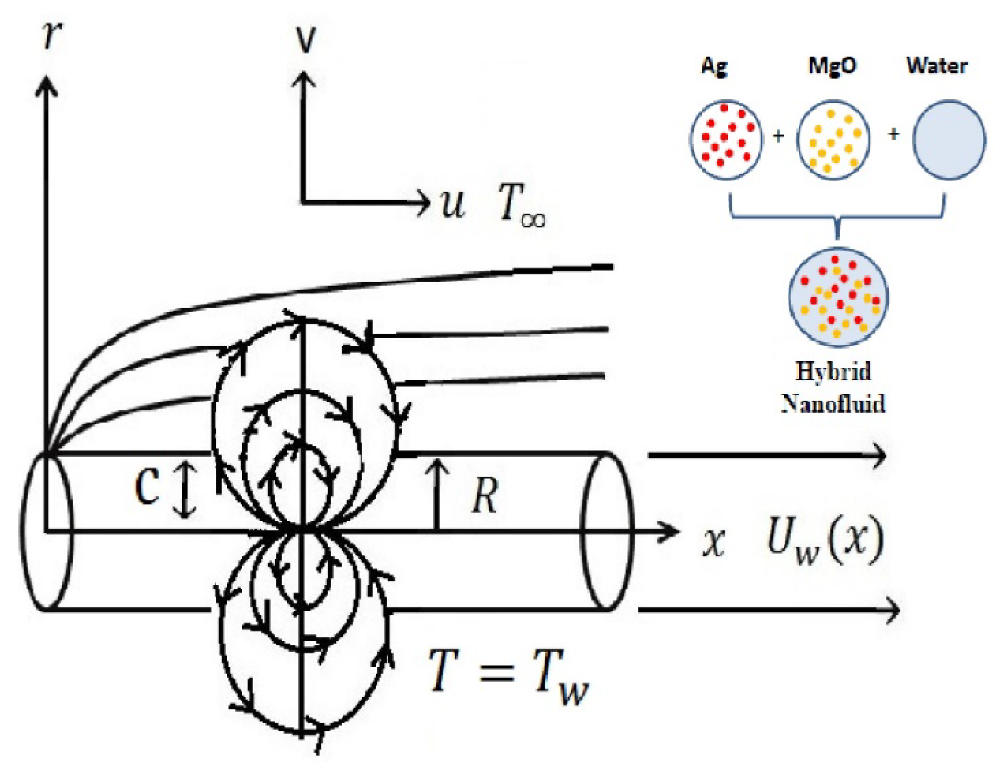
2. Mathematical Modelling

Here, we consider a 2D laminar, incompressible, and radiative Casson hybrid nanomaterial liquid flow on a stretching cylinder in the presence of the slip and microorganism effects. The energy and mass concentration equation has been analyzed by the influence of viscous dissipation and modified Fick’s law. Moreover, the stratification boundary conditions are implemented on the surface and away from the surface. A magnetic dipole is considered with a magnetic field in the direction of x . The coordinates axes are x and r , R is the radius of the cylinder, and U w is the stretching velocity. The flow pattern is seen in Figure 1. The ambient temperature, concentration, and microorganism density are denoted by T , C , and N , respectively, and at the wall they are stated by T w , C w , and N w , respectively.
Using the above-mentioned supposition and boundary layer approximation theory, the flow equations are developed as [25,26,27],
( r u ) x + ( r v ) r = 0 ,
u u x + v u r = μ h n f ρ h n f ( 1 + 1 β ) ( 2 u r 2 + 1 r u r ) + μ 0 ρ h n f M H x ,
u T x + v T r = α h n f ( 2 T r 2 + 1 r T r ) μ 0 T M T ( u H x + v r H r ) + 1 ( ρ c p ) h n f ( μ h n f ( 1 + 1 β ) ( u y ) 2 + 16 σ T 3 3 k ( 2 T r 2 + 1 r T r ) ) ,
u C x + v C r = ( D B ) h n f ( 2 C r 2 + 1 r C r ) λ c ( v v r C r + v u r C x + u v x C r + u u r C x + 2 u v 2 C x r + u 2 2 C x 2 + v 2 2 C r 2 ) ,
u N x + v N r + b W c C w C 0 r ( N C r ) = ( D m ) h n f ( 2 N r 2 + 1 r N r ) .
where μ 0 M H x represents the ferromagnetic force per unit volume.
The associated boundary conditions are,
v = 0 ,    u = U w + w 1 ν h n f ( 1 + 1 β ) u r , T = T 0 + b x l , C = C 0 + d x l ,   N = N 0 + a x l ,   at   r = R ,
u 0 ,    T T ( x ) = T 0 + c x l ,   C C ( x ) = C 0 + e x l ,   N N = N 0 + a 1 x l ,   as   r .
In the above equations, u and v are the velocity components in the directions of x and r , respectively. Additionally, the μ h n f is the dynamic viscosity of the hybrid nanofluid, ρ h n f is the density of the hybrid nanofluid, α h n f is the thermal diffusivity of the hybrid nanofluid, k is the mean absorption coefficient, ( D B ) h n f is the mass diffusivity of the nanofluid, ( D m ) h n f is the microorganism diffusivity of the nanofluid, w 1 is the slip factor, λ c is the concentration relaxation time, ν h n f is the kinematic viscosity of the hybrid nanofluid, and W c is the maximum cell swimming speed. Additionally, a ,   b , c , d , e , and a 1 signify the positive constants. Table 1 represents the thermophysical properties of the base fluid and nanoparticles.
The hypothetical relation is characterized as follows,
σ r = σ h n f σ f = [ 1 + 3 ( σ σ f 1 ) ( ϕ M g O + ϕ A g ) ( σ σ f + 2 ) ( σ σ f 1 ) ( ϕ M g O + ϕ A g ) ] ,
( ρ c ) r = ( ρ c ) h n f ( ρ c ) f = ( 1 + ϕ M g O ϕ A g ) + ϕ A g ( ρ c ) A g ( ρ c ) f + ϕ M g O ( ρ c ) M g O ( ρ c ) f ,
ρ r = ρ h n f ρ f = ( 1 + ϕ M g O ϕ A g ) + ϕ A g ρ A g ρ f + ϕ M g O ρ M g O ρ f ,
μ r = μ h n f μ f = [ 1 + 32.795 ϕ 1 7214 ϕ 1 2 + 714600 ϕ 1 3 0.1941 × 10 8 ϕ 1 4 ] ; 0 ϕ 1 0.02 ,
k r = k h n f k f = [ 0.1747 × 10 5 + ϕ 1 0.1747 × 10 5 0.1498 × 10 6 ϕ 1 + 0.1117 × 10 7 ϕ 1 2 + 0.1997 × 10 7 ϕ 1 3 ] ; 0 ϕ 1 0.03 .

2.1. Magnetic Dipole

The scalar potential of the magnetic dipole is stated as,
Ω = x l 2 π ( x 2 + ( r + c ) 2 ) ,
In Equation (13), l specifies the magnetic strength. The horizontal and vertical part of the magnetic field in x and r directions are defined as,
H x = Ω x = x 2 ( r + c ) 2 2 π ( x 2 + ( r + c ) 2 ) ,
H r = Ω r = 2 x ( r + c ) 2 π ( x 2 + ( r + c ) 2 ) 2 .
The absolute magnetic field and magnetic body force is stated as,
H = ( H x ) 2 + ( H r ) 2 .
where the components in the square root are defined as,
H x = 2 x 2 π ( r + c ) 4 ,
H r = 1 2 π ( 2 ( r + b ) 3 + 4 x ( r + c ) 5 ) .
The intensity of the magnetic field became stronger and formed a linear relationship between temperature and magnetic variation:
M = K * ( T T ) .
For the discussion of the ferrodynamic interaction, we may suppose that the magnetic field is applied in a non-homogenous way, and fluid temperature must be less than the Curie temperature.

2.2. Similarity Transformation

The similarity variables are stated as,
η = ( U w l ν f ) 1 / 2 ( r 2 R 2 2 R ) ,   u = U w f ( η ) , v = ( ν f U 0 l ) 1 / 2 R r f ( η ) ,   θ ( η ) = T T T w T 0 ,   g ( η ) = C C C w C 0 ,    h ( η ) = N N N w N ,
Equation ( 1 ) is identically satisfied and other Equations (2)–(7) yield,
( 1 + 1 β ) A 1 A 2 ( ( 1 + 2 α η ) f + 2 α f ) + f f f 2 2 M θ ( η + γ 1 ) 4 A 2 = 0 ,
( k h n f k f + 4 3 R d ) ( ( 1 + 2 α η ) θ + 2 α θ ) + Pr ( f θ 2 f θ S 1 f + E c ( 1 + 1 β ) f 2 ) 2 λ M ( θ ε ) f ( γ 1 + η ) 3 2 λ f 2 = 0 ,
A 1 S c ( ( 1 + 2 α η ) g + 2 α g ) + f g 2 g f S 2 f γ c ( f 2 g + f f g ) = 0 ,
A 1 ( ( 1 + 2 α η ) h + 2 α h ) + L b ( f h 2 f h S 3 f ) P e ( h g + ( h + δ ) ( ( 1 + 2 α η ) g + 2 α g ) ) = 0 ,
The concerned boundary condition becomes,
f ( 0 ) = 0 , f ( 0 ) = 1 + ( 1 + 1 β ) s A 1 f ( 0 ) ,   θ ( 0 ) = 1 S 1 ,   g ( 0 ) = 1 S 2 ,   h ( 0 ) = 1 S 3 ,   f ( ) 0 ,   θ ( ) 0 ,   g ( ) 0 ,   h ( ) 0
.
The developed parameters are the curvature parameter, the Casson fluid parameter, the ferromagnetic parameter, the Eckert number, the radiation parameter, the free stream parameter, the Prandtl number, the viscous dissipation parameter, the concentration relaxation parameter, the Schmidth number, the bio-convection Lewis number, the Peclet number, the velocity slip parameter, the thermal stratification parameter, the solutal stratification parameter, the bio-convection constant, and the microorganism stratification parameter, which are symbolized by α , β , M , E c , R d , ε , P r , λ , γ c , S c , L b , P e , s , S 1 , S 2 , δ , and S 3 , respectively. These parameters are mathematically defined as,
Pr = ν f α f ,   α = ( ν f l U 0 R 2 ) 1 / 2 ,    S 1 = c b ,   S c = υ f D B ,   S 2 = e d ,   S 3 = a 1 a , L b = ν f D m ,   M = γ 1 μ 0 K * ( T 0 T w ) ρ f 2 π μ f 2 ,   γ 1 = ( ρ f U 0 b 2 μ f ) 1 / 2 , λ = μ f 2 U 0 ρ f k ( T 0 T w ) ,   s = w 1 U 0 ν f l ,   P e = b W c D m ,   E c = U 0 2 c p ( T w T ) ,    δ = N N w N .
The physical quantities of interest in this study are the skin friction, the local Nusselt number, the Sherwood number, and the microorganism number, which are defined by,
C f = 2 τ w ρ f u w 2 , N u x = x q w k f ( T w T 0 ) ,   S h x = x q m D B ( C w C 0 ) , N n x = x q n D m ( n w n ) .
The nondimensional forms of physical quantities are,
C f Re x 1 / 2 = 1 A 1 ( 1 + 1 β ) f ( 0 ) , N u x Re x 1 / 2 = k h n f k f θ ( 0 ) , S h x Re x 1 / 2 = g ( 0 ) ,    N n x Re x 1 / 2 = h ( 0 ) .

3. Result and Discussion

In this section, the graphical and tabulated discussion of the two-dimensional radiative Casson fluid flow with viscous dissipation and modified Fick’s law with stratification boundary conditions on the cylindrical surface is presented. The flow model solution is obtained with the help of the MATLAB built-in function Bvp4c. The comparison table of the current problem with data published by Nadeem et al. [1] and Bidin and Nazar [2] is presented in Table 2. It is shown that a stronger value of the Prandtl number improves the temperature gradient. Table 3 shows the variation in the skin friction coefficient, and the rates of heat transfer, mass transfer, and microorganism transfer against M , α , and ϕ 1 . It is quite interesting to see that the skin friction coefficient improves for the improved values of M , while heat, mass, and microorganism transfer rates decline for the stronger values of M . Further, α and ϕ 1 show increasing behavior against the skin friction, and the heat, mass, and microorganism transfer rates. The effect of L b , P e , α , and δ on the microorganism transfer rate by the influence of Ag and MgO is found in Table 4. It is noted that a larger estimation of L b , Pe, α , and δ improves the microorganism transfer rate for both of the nanoparticles.

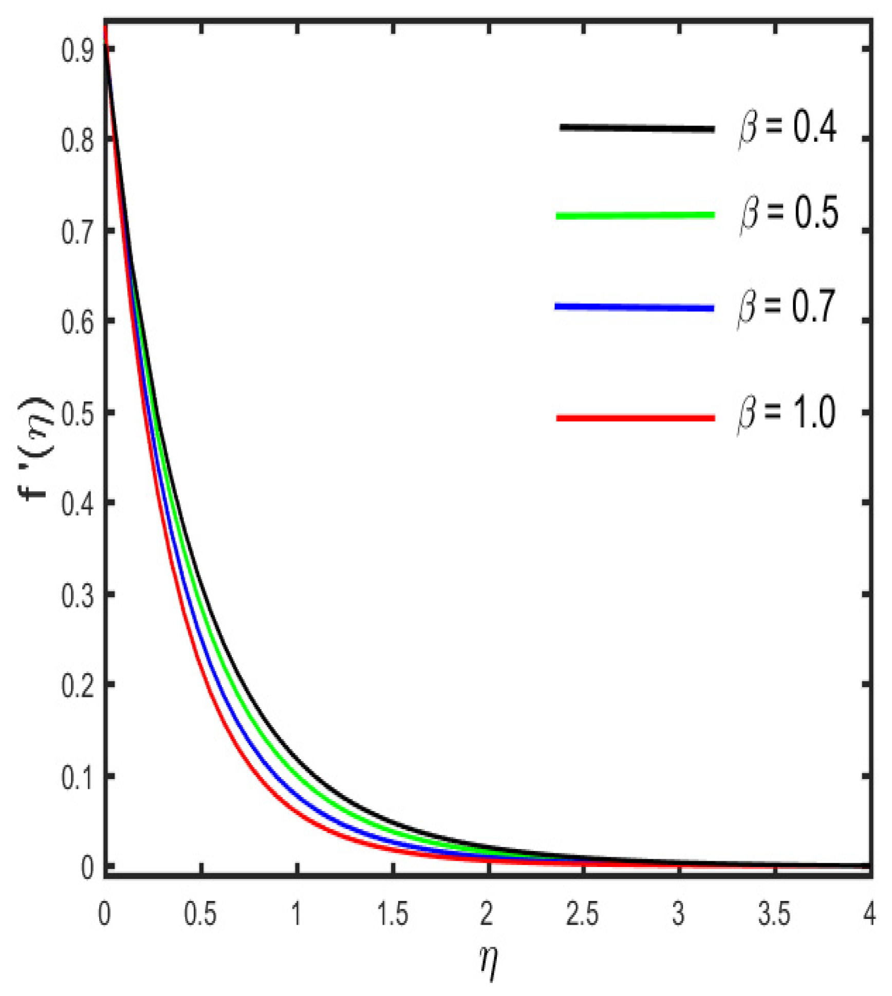
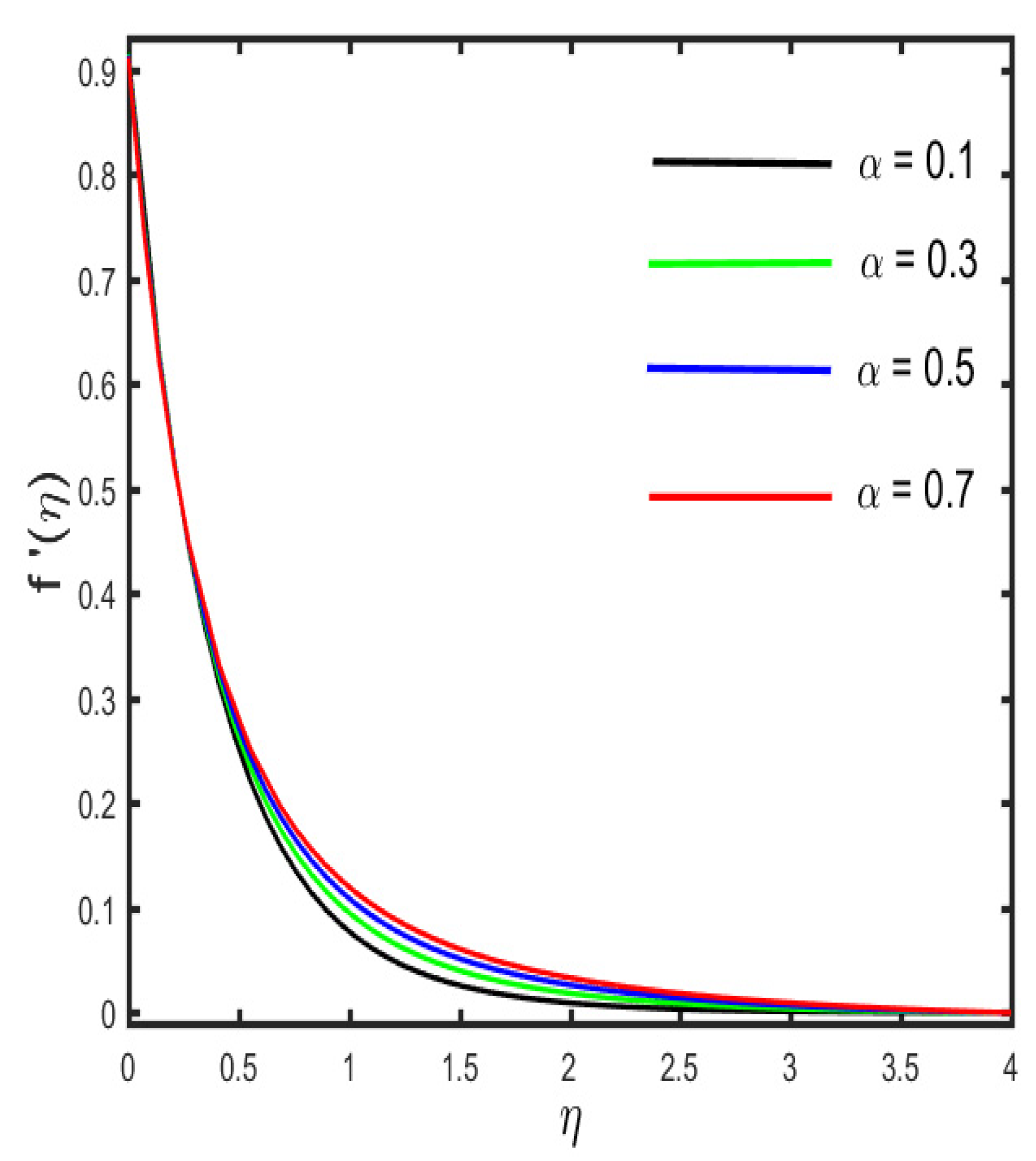
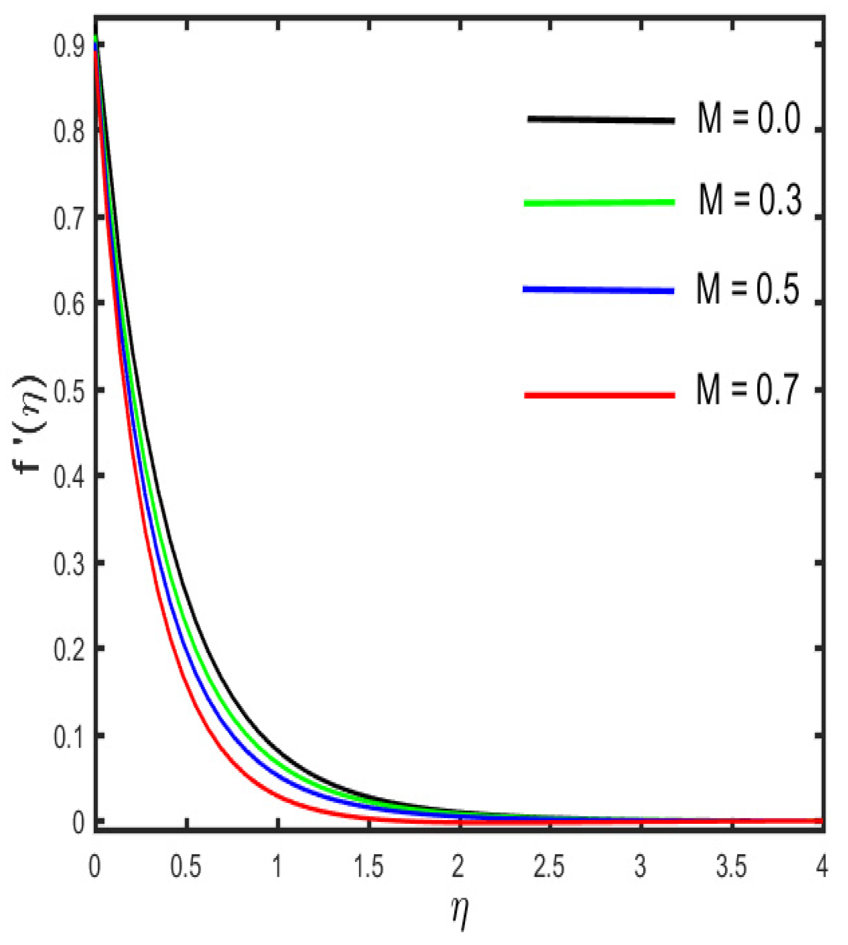
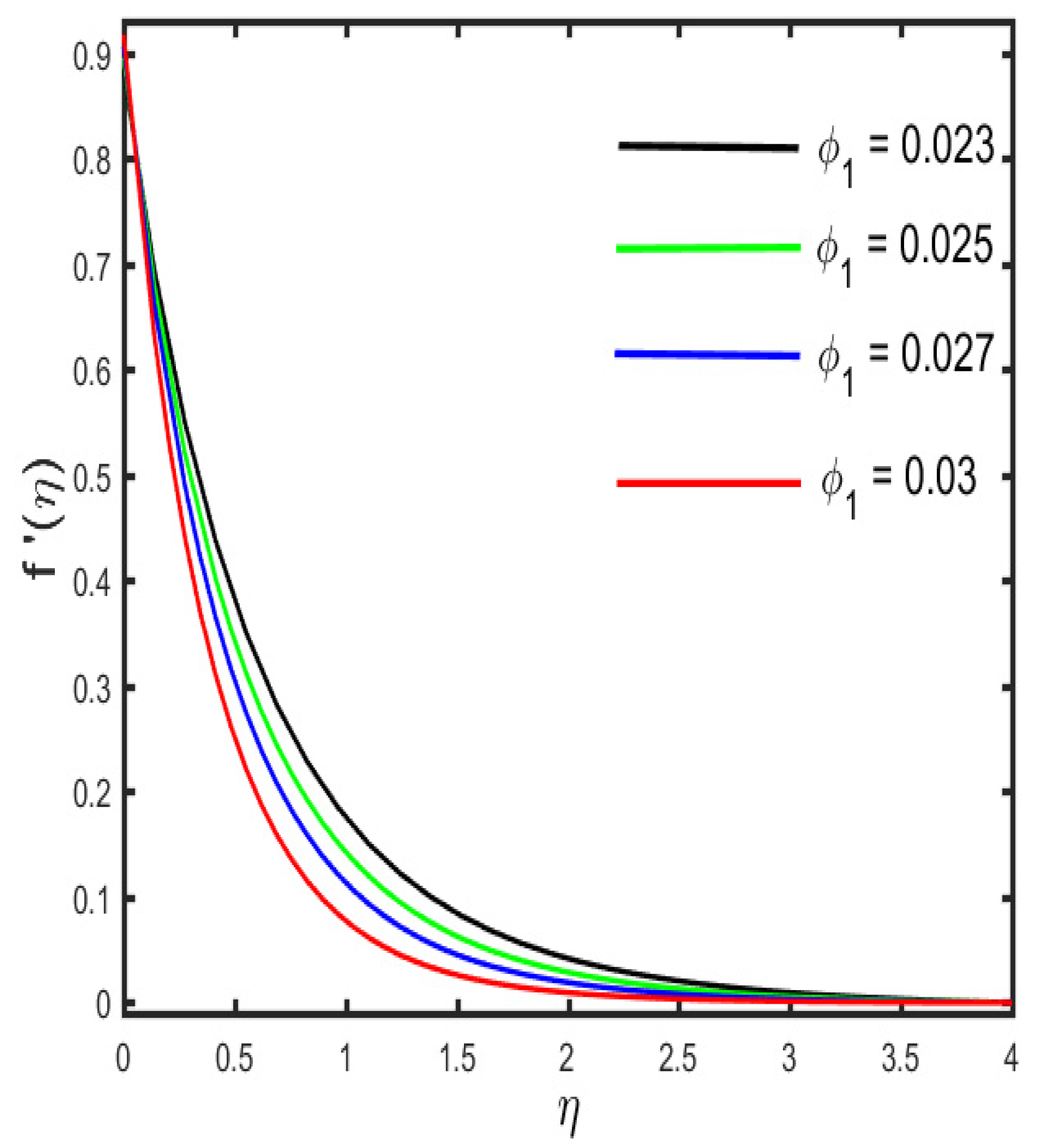
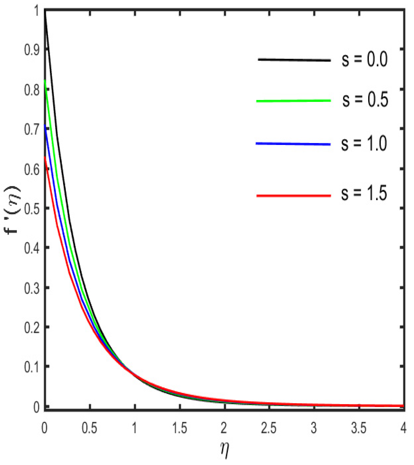
3.1. Variation in Velocity Profile for Different Parameters

The variation in the velocity profile for the several parameters is depicted in Figure 2, Figure 3, Figure 4, Figure 5 and Figure 6. The results, indicated in Figure 2, are that the velocity profile shows a decreasing trend for the improved values of the Casson fluid parameter, while a stronger estimation of α shows the opposite trend on the velocity profile, which is lessening (see in Figure 3). The reason behind this is that the stronger resistive force occurs between the molecules of the solid surface at the wall by the escalation of the curvature parameter. Further, it is found that by the expansion of α (the curvature parameter), the radius of the cylinder condenses, thereby the low resistance is provided to the fluid motion, and hence, the fluid velocity rises. The diversion in the velocity sketch against the various values of the magnetic parameter and solid fraction parameter is found in Figure 4 and Figure 5. It is clarified in Figure 4 that due to the occurrence of the magnetic effect, the Lorentz force appears, which yields the retardation effect whereby the fluid velocity declines. Further, the result of Figure 5 illustrates the reducing behavior by the escalation of ϕ 1 . The influence of s (velocity slip parameter) on the velocity profile is designated in Figure 6. The figure shows that declines in the fluid velocity due to increasing values of s are related to boundary layer thickness. The reason behind this is that the velocity near the cylindrical surface is not the same as the velocity away from the surface, and, therefore, the fluid velocity diminishes.

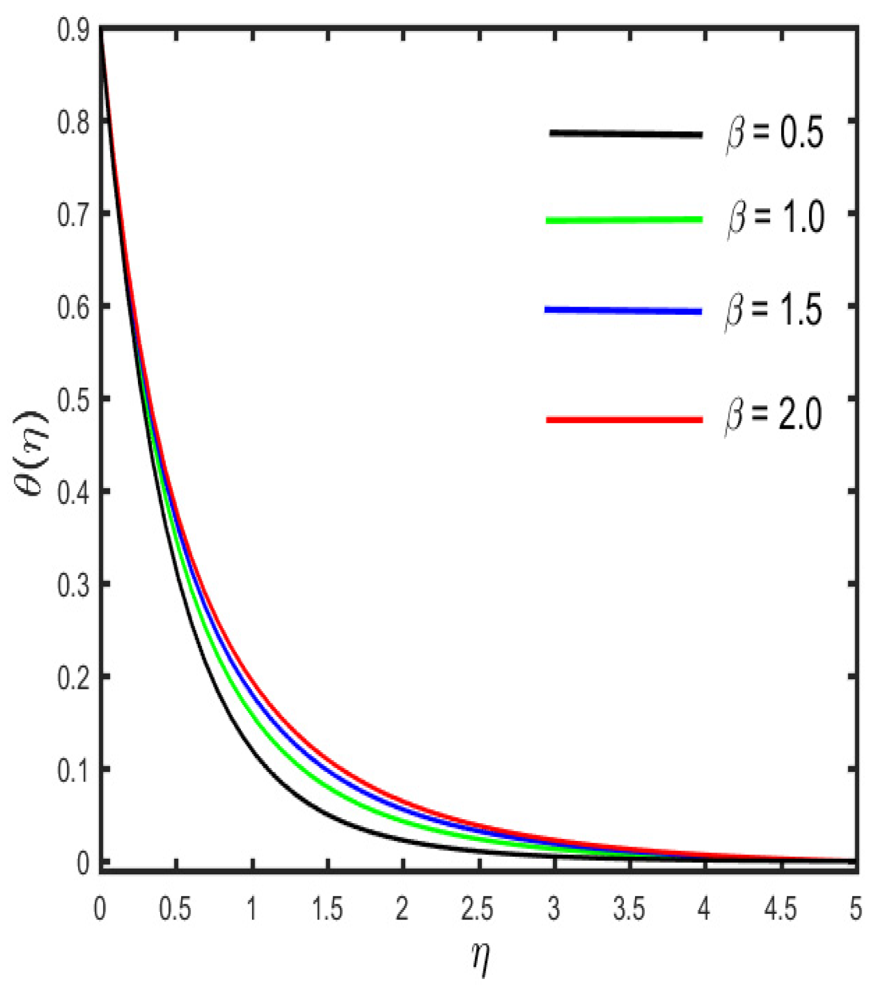
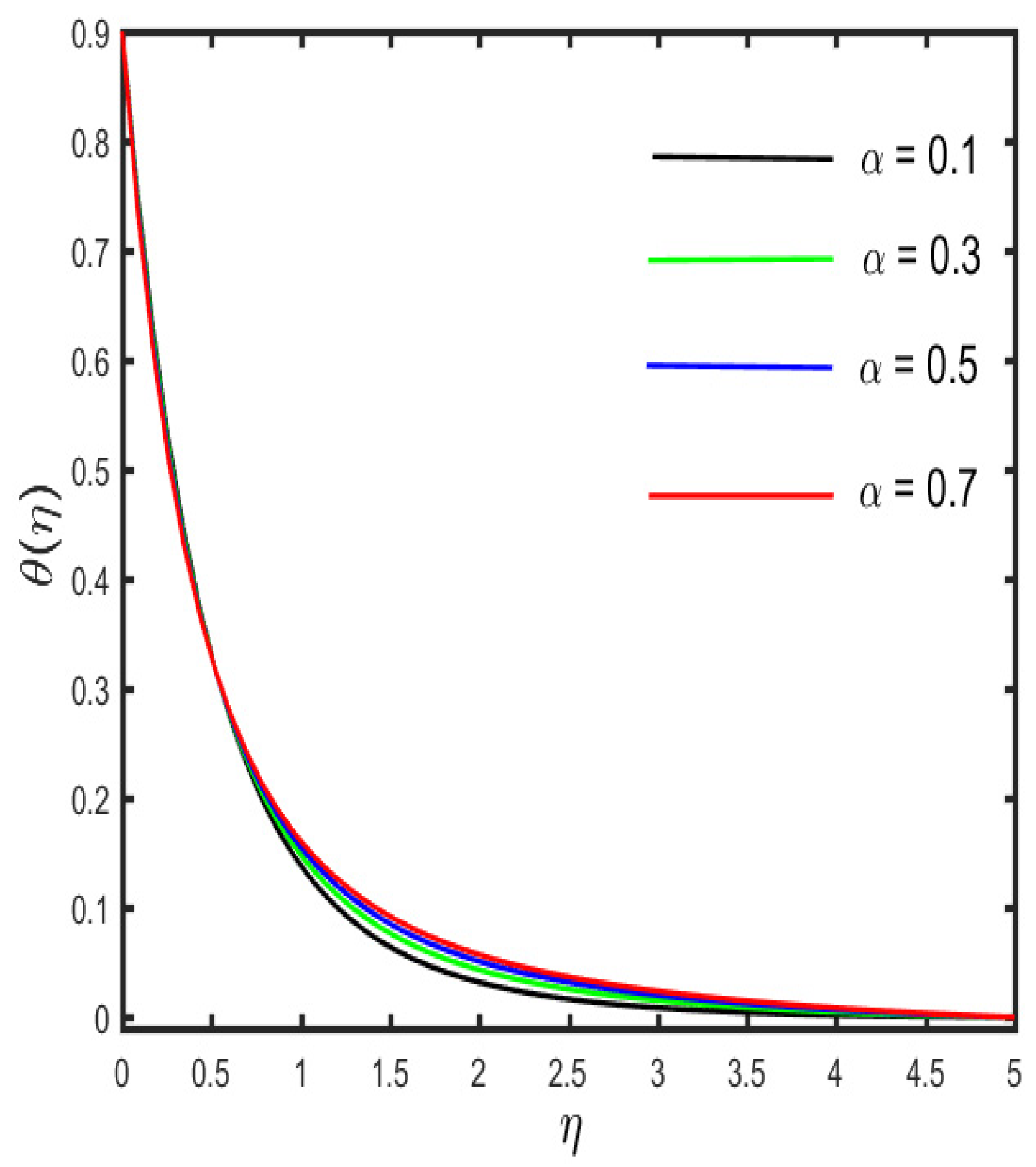
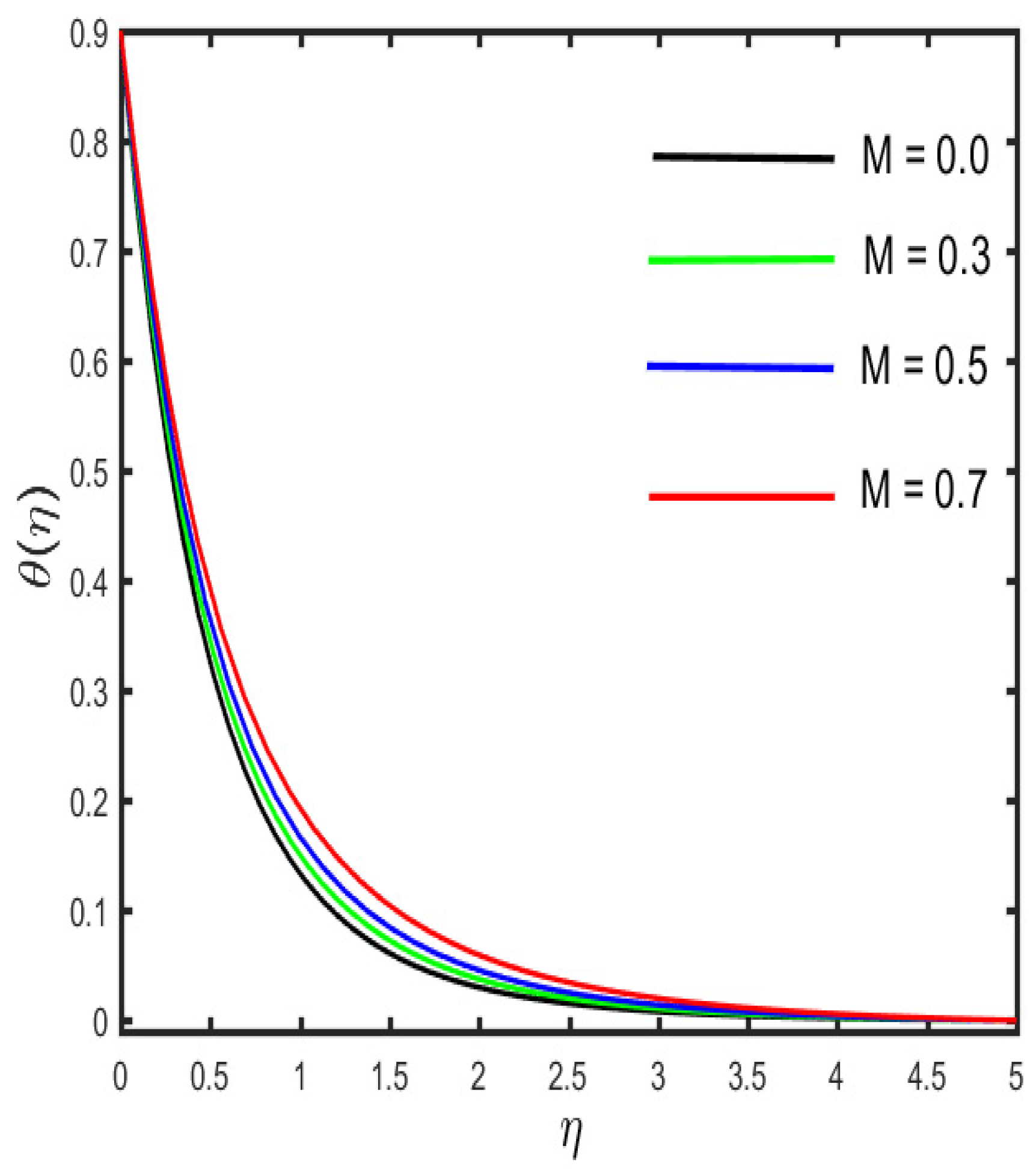
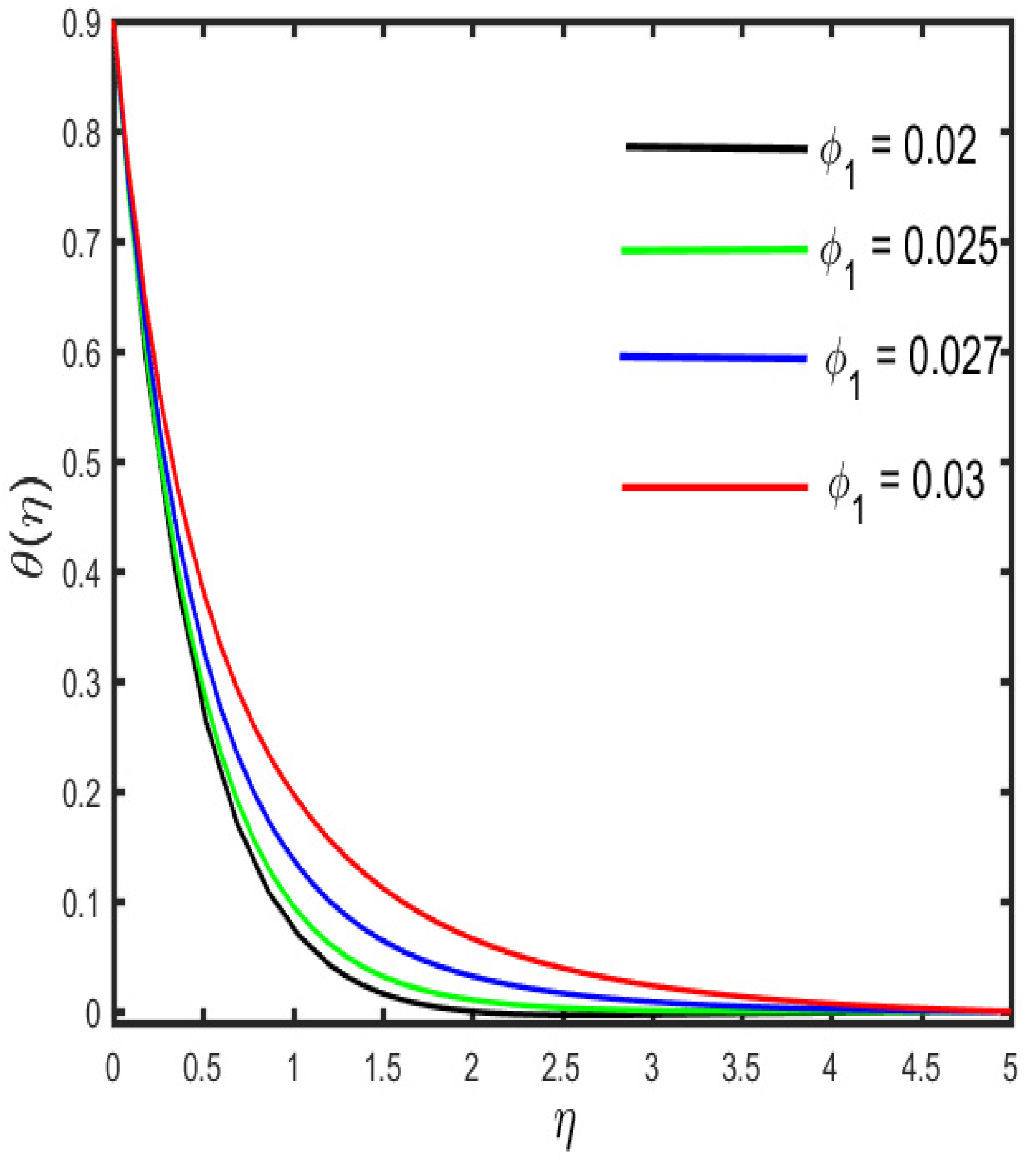
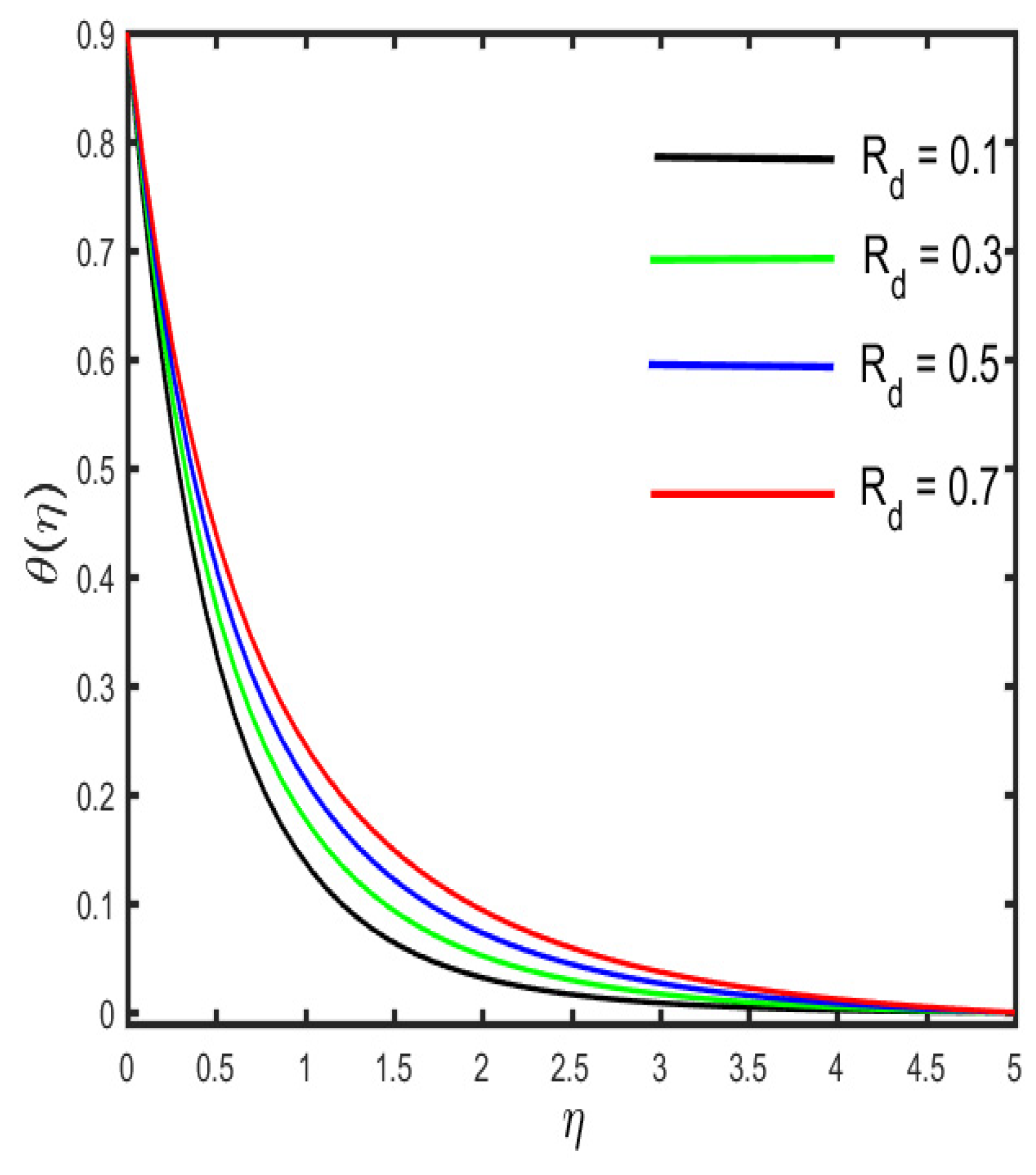
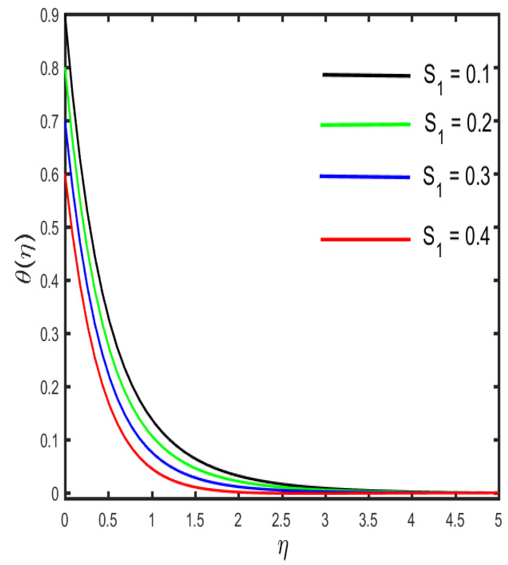
3.2. Variation in Temperature Sketch against Various Parameters

The outcomes of several parameters on the temperature profile are observed in Figure 7, Figure 8, Figure 9, Figure 10, Figure 11 and Figure 12. The diverse features of β (the Casson fluid parameter) and α (the curvature parameter) on the temperature distribution are presented in Figure 7 and Figure 8. It is represented in the figures that the temperature distribution improves with improved values of β and α , consequently. Figure 9 and Figure 10 demonstrate the behavior of M (the magnetic parameter) and ϕ 1 (the solid volume fraction parameter) on the temperature distribution. It is clarified in the figures that increases in the fluid temperature coincided with increases in the estimations of both of the parameters M and ϕ 1 . The various consequences of R d (the radiation parameter) and S1 (the stratification parameter) against the temperature of the fluid are presented in Figure 11 and Figure 12. It is worth mentioning, in the figures, that the strong values of R d and S 1 increase the temperature and the corresponding boundary layer thickness. Physically, the mean absorption coefficient is reduced for a stronger estimation of the radiation parameter, which consequently expands the thermal distribution. Furthermore, as the reason behind the variations of temperature, the stratification between the surface and away from the surface decreases, and ultimately, the temperature decreases.

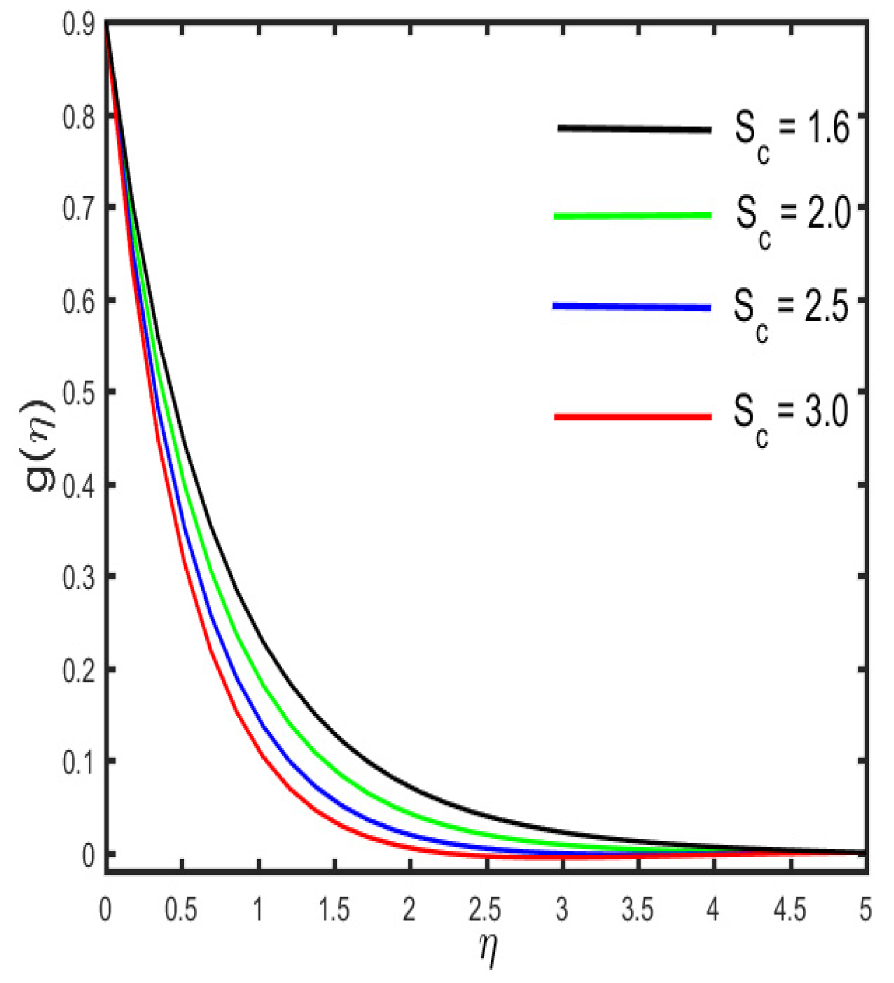
3.3. Variation in Concentration Sketch against Various Parameters

Figure 13, Figure 14, Figure 15, Figure 16 and Figure 17 illustrate the effects of various emerging parameters on the concentration sketch. The variation in the g ( η ) sketch against the various estimation of α and γ c (the mass relaxation parameter) is portrayed in Figure 13 and Figure 14. Figure 13 illustrates that higher values of α boost the concentration sketch and the related thickness of the boundary layer. Further, it is designated that a stronger estimation of the mass relaxation parameter declines as the concentration profile and the associated boundary layer become thicker (see in Figure 14). It is interesting to note that the enhancement occurs in the concentration sketch against the escalation of ϕ 1 , which is seen in Figure 15. Figure 16 represents the effect of S 2 (the concentration stratification) on the concentration distribution. It is visible in the figure that the reduction occurs in the g ( η ) sketch and the associated boundary layer thickness by the enhancement of S 2 . The characteristics of S c (the Schmidth number) on the concentration sketch is examined in Figure 17. It is sketched that the stronger estimation of S c declines as the nanoparticle concentration and corresponding boundary layer become thinner. Physically, by the enhancement of S c , mass diffusivity decays, and, as a result, the concentration sketch declines.

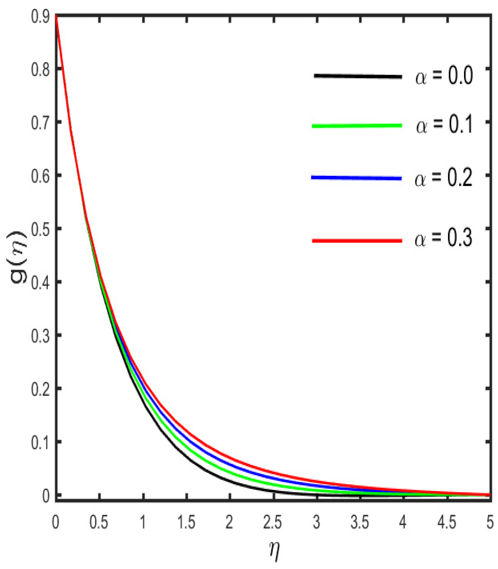
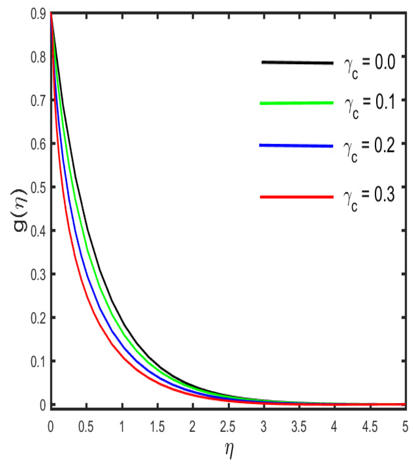
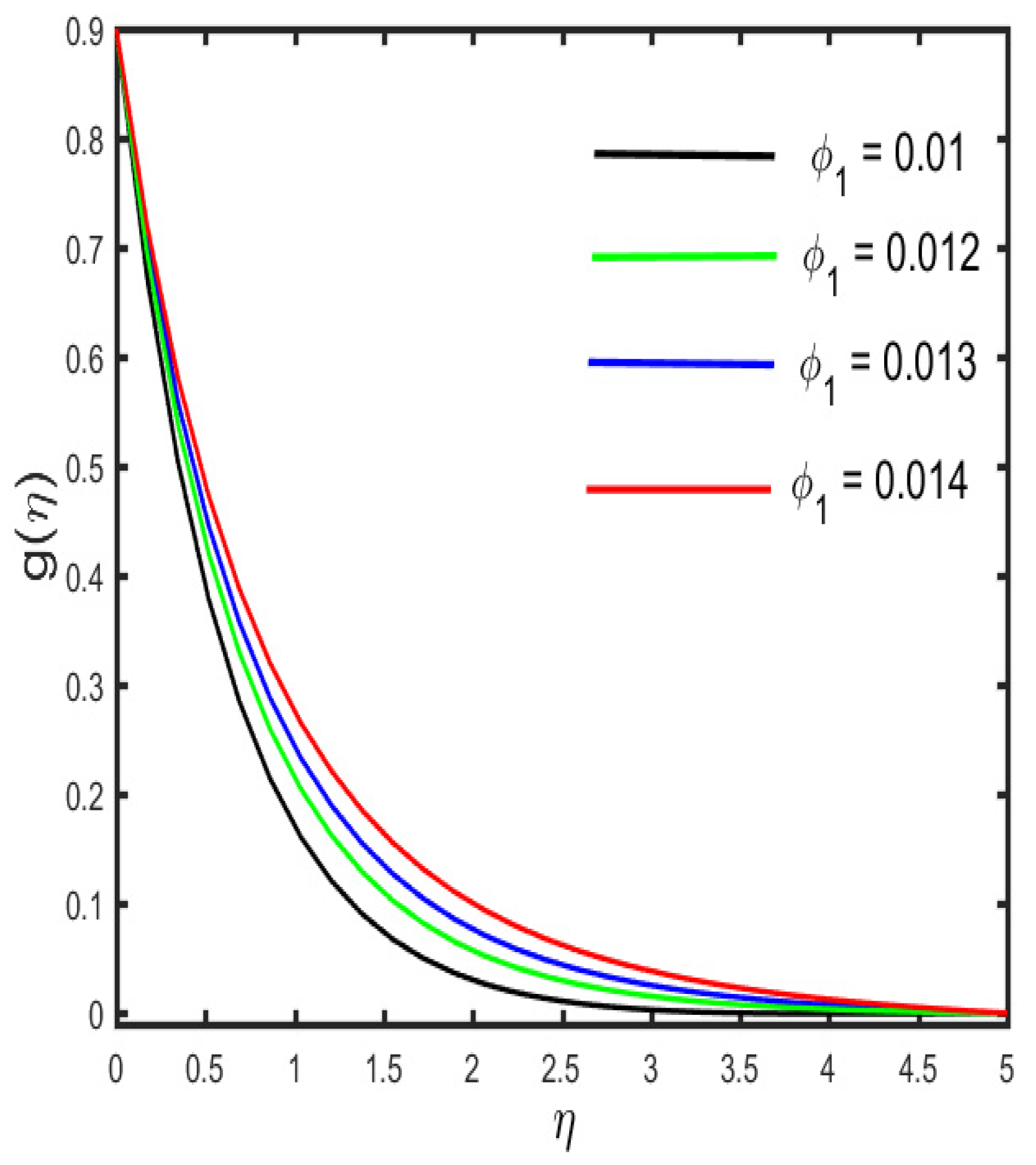
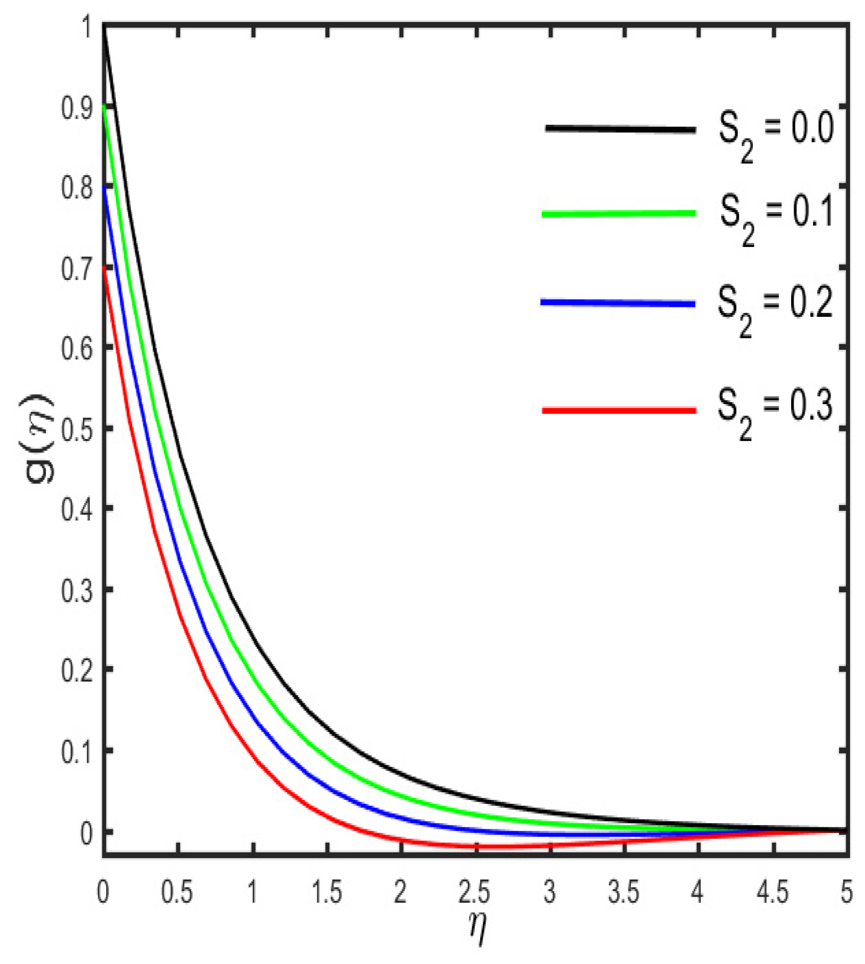
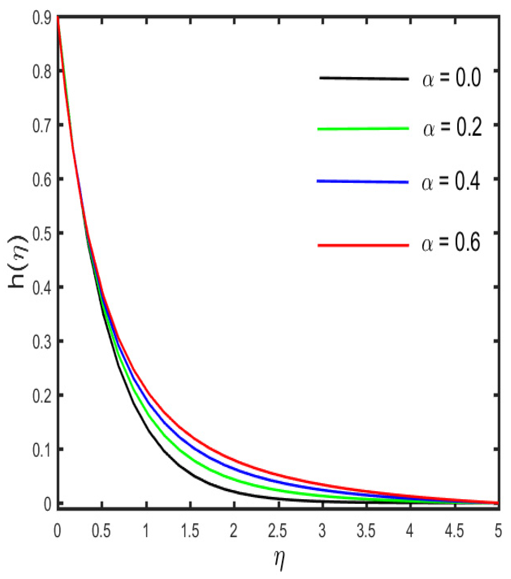
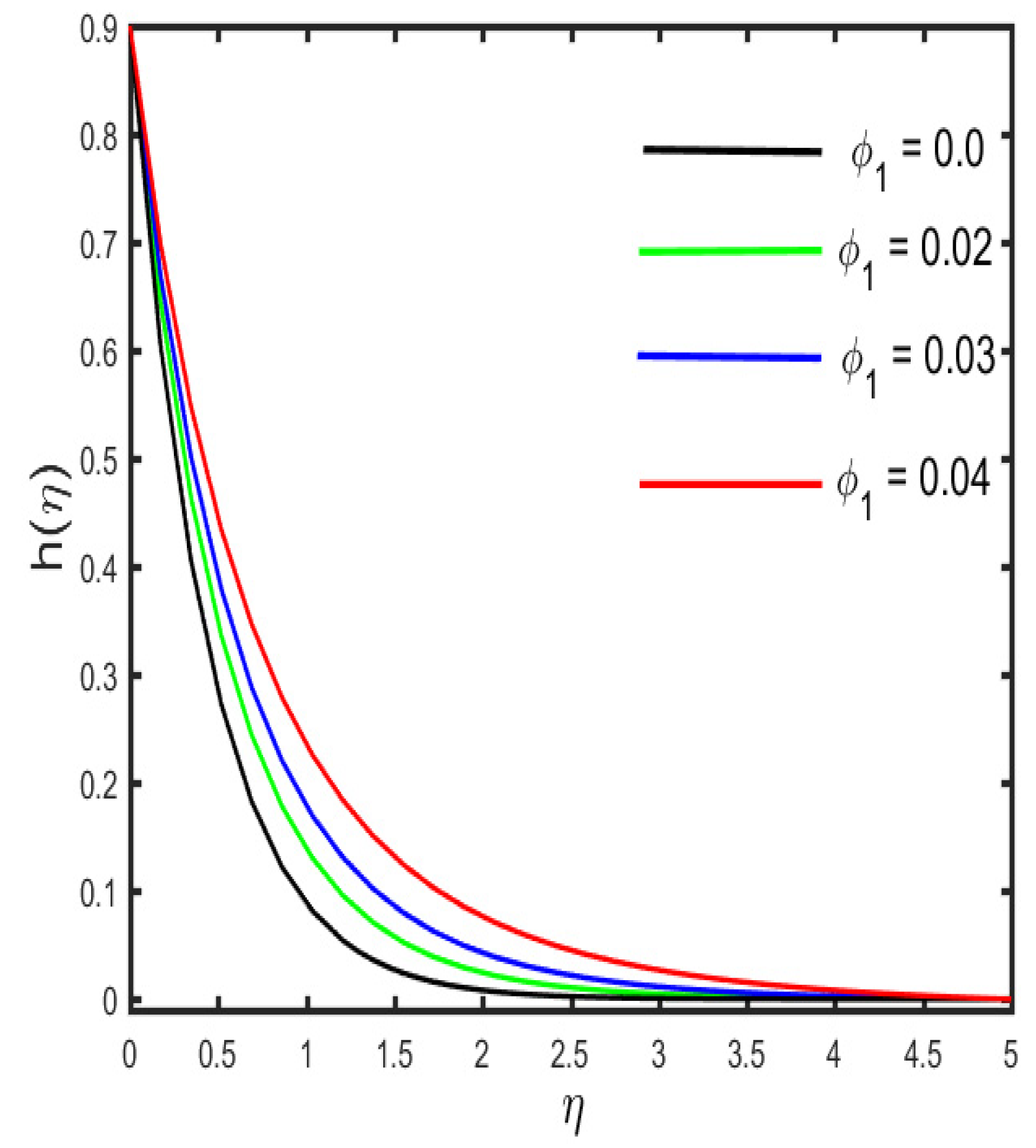
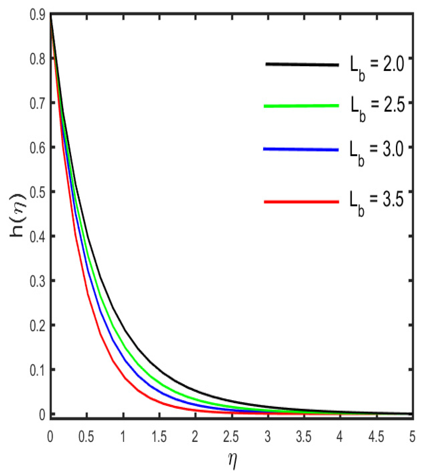
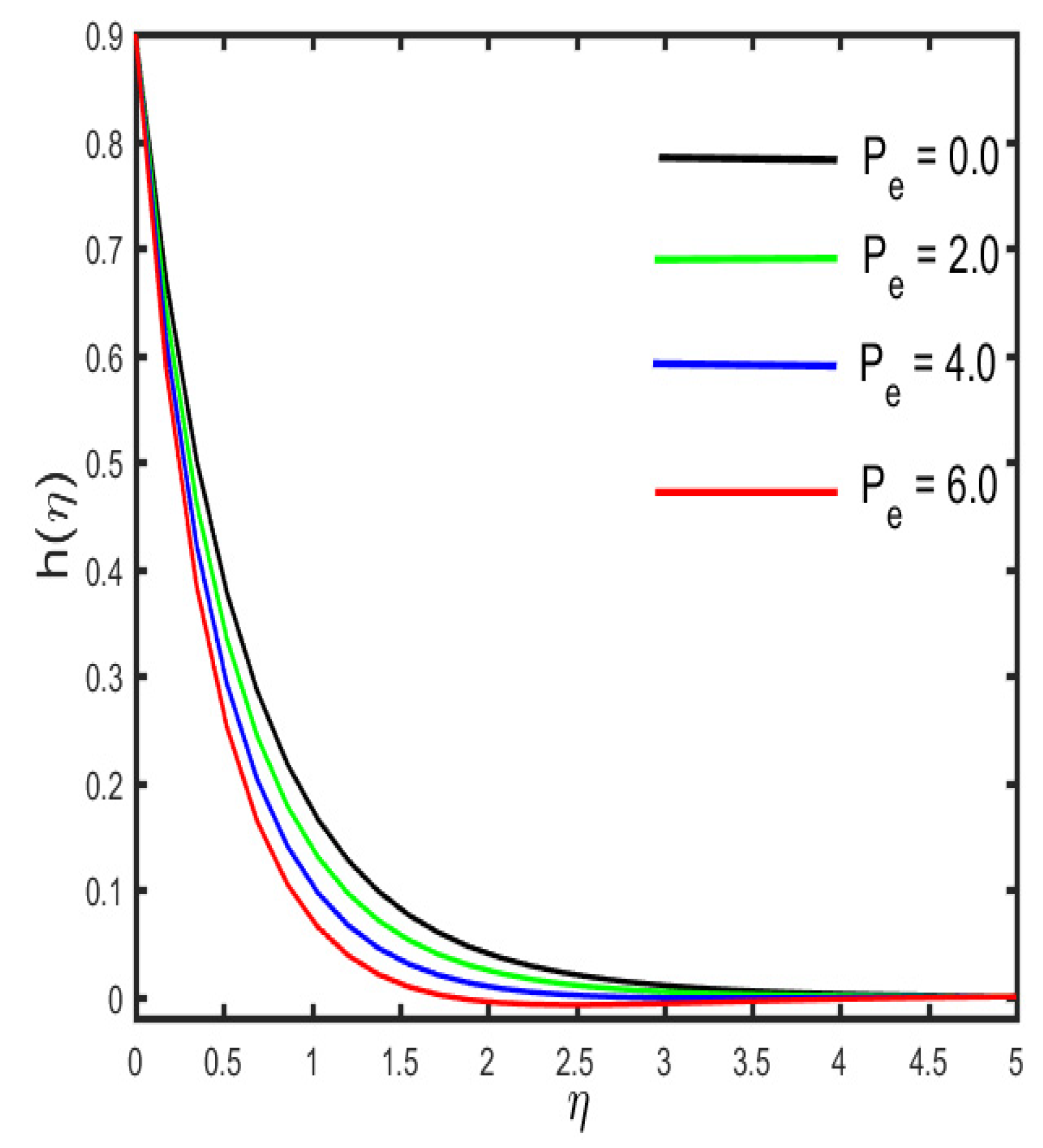
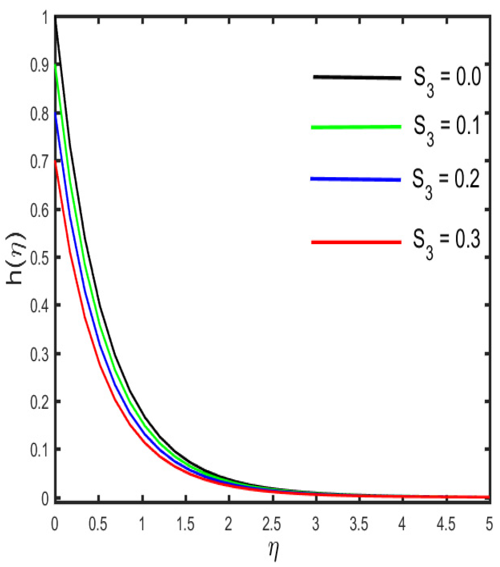
3.4. Variation in Microorganism Profile against Different Parameters

Figure 18, Figure 19, Figure 20, Figure 21 and Figure 22 represent the consequences of the different parameters on the microorganism density distribution. The effects of α and ϕ 1 on the microorganism density sketch are observed in Figure 18 and Figure 19. It is clarified from the figure that the microorganism density and the related boundary layer thickness show an enhancing trend for the higher values of α and ϕ 1 . The effect of L b (the bio-convection Lewis number) and P e (the Peclet number) on the microorganism sketch is represented in Figure 20 and Figure 21. It is quite interesting to note that the microorganism density profile improves for higher values of both L b and P e . The reason behind this is that microorganism diffusivity declines with increasing values of L b , and, as a result, the density of nanoparticles and the related boundary layer declines. Further, it is noted that non-negative values of P e subvert the gyrotactic microorganism thickness and higher P e improves the movement of liquid particles; hence, slender microorganisms can be seen. The salient feature of S 3 (the microorganism stratification parameter) on the h ( η ) sketch is described in Figure 22. It is shown in the figure that a reduction occurs in the microorganism density of nanoparticles and the boundary layer becomes thinner with the improvements of S3.

4. Concluding Remarks

The consideration of two-dimensional radiative Casson fluid flow with a magnetic dipole and microorganisms is presented in the article. The mass and heat transport analyses are observed under the influence of viscous dissipation and generalized Fick’s law. The stratification boundary conditions are implemented at the boundary of the cylindrical surface and away from the boundary. The main result of the above observation is as follows:
  • The fluid velocity is augmented with the increase in the curvature parameter, while a decrease occurs in the fluid velocity by the increase in the magnetic and slips parameters.
  • The fluid velocity decreases with increases in β and ϕ 1 .
  • The temperature and concentration of the fluid are improved for strong values of the curvature parameter.
  • Stronger estimation of thermal and concentration stratification consequently decreases the fluid concentration and temperature.
  • The microorganism concentration declines for the microorganism stratification parameter, while showing an opposite trend for an increasing amount of the curvature parameter.
  • The skin friction shows a declining trend for the improved values of M , but the heat transfer rate shows increasing behavior.
  • The heat and mass transfer rates show increasing trends for larger values of α and ϕ 1 .
  • The microorganism transfer rate is improved for increasing values of L b and P e , but it shows an opposite trend for the larger values of M .

Author Contributions

S.A.: Conceptualization, Data curation, Writing—original draft, M.N.K.: Formal analysis, Validation, A.R.: Software, Resources, Writing—review & editing, B.F.F.: Funding acquisition, Writing—review & editing, Investigation, M.S.A.: Funding acquisition, Writing—review & editing, Visualization, F.M.A.: Writing—review & editing, validation, F.A.: Methodology, Writing—review & editing, A.M.G.: Methodology, Writing—review & editing, Resources. All authors have read and agreed to the published version of the manuscript.

Funding

Taif University Researchers Supporting Project number (TURSP-2020/260), Taif University, Taif, Saudi Arabia.

Data Availability Statement

Data is contained within the article.

Acknowledgments

Taif University Researchers Supporting Project number (TURSP-2020/260), Taif University, Taif, Saudi Arabia.

Conflicts of Interest

Authors have no conflict of interest regarding this publication.

Nomenclature

u ,   v Velocity Components Greek Symbols
x, rCoordinate ρ h n f , ρ f Density
M magnetization μ h n f , μ f Dynamic viscosity
H magnetic field τ x y Shear stress
T ,    T w Temperature, and wall temperature α h n f ,   α f Modified thermal diffusivity
DmDiffusivity of microorganisms ( ρ C p ) h n f , ( ρ C p ) f heat capacity
PrPrandtl number k f , k h n f Thermal conductivity
C p Specific heat ϕ Solid volume fraction of a nanofluid
U w Stretching velocity along x-directionηScaled boundary-layer coordinate
D B Brownian diffusion coefficient Ω magnetic scalar potential
E c Eckert number μ 0 magnetic permeability
Cfsurface drag force q w ( x ) the surface heat flux of a nanoliquid film
N u x Nusselt number β Casson fluid parameter
P e Bioconvection Péclet number λ viscous dissipation parameter
a ,   b , c , d , e Positive constants σ * Stefan–Boltzmann constant
s velocity slip parameter θ Dimensionless temperature
S c Schmidt number δ Bioconvection constant
W c Maximum cell swimming speed α Curvature parameter
Re x Local Rayleigh number λ c concentration relaxation time
w 1 Slip factor ε Curie temperature
l strength of magnetic field
K * pyromagnetic co-efficient
k mean absorption coefficient
S 1 Thermal stratification
S 2 Solutal stratification
S 3 microorganism stratification
Subscripts
w The boundary surface The ambient surface
h n f Hybrid nanofluid n f Nanofluid

References

  1. Yellen, B.B.; Friedman, G.; Fridman, G. Ferrofluid lithography. Nanotechnology 2004, 15, S562–S565. [Google Scholar] [CrossRef]
  2. Ashouri, M.; Ebrahimi, B.; Shafii, M.B.; Saidi, M. Correlation for Nusselt number in pure magnetic convection ferrofluid flow in a square cavity by a numerical investigation. J. Magn. Magn. Mater. 2010, 322, 3607–3613. [Google Scholar] [CrossRef]
  3. Chang, C.-H.; Tan, C.-W.; Miao, J.; Barbastathis, G. Self-assembled ferrofluid lithography: Patterning micro and nanostructures by controlling magnetic nanoparticles. Nanotechnology 2009, 20, 495301. [Google Scholar] [CrossRef]
  4. Vales-Pinzón, C.; Alvarado-Gil, J.J.; Medina-Esquivel, R.; Martínez-Torres, P. Polarized light transmission in ferrofluids loaded with carbon nanotubes in the presence of a uniform magnetic field. J. Magn. Magn. Mater. 2014, 369, 114–121. [Google Scholar] [CrossRef]
  5. Hatch, A.; Kamholz, A.; Holman, G.; Yager, P.; Bohringer, K. A ferrofluidic magnetic micropump. J. Microelectromech. Syst. 2001, 10, 215–221. [Google Scholar] [CrossRef] [Green Version]
  6. Papell, S.S. Low Viscosity Magnetic Fluid Obtained by the Colloidal Suspension of Magnetic Particles Patent. 1965. Available online: https://ntrs.nasa.gov/api/citations/19700030808/downloads/19700030808.pdf (accessed on 24 October 2021).
  7. Kumar, V.; Madhukesh, J.; Jyothi, A.; Prasannakumara, B.; Khan, M.I.; Chu, Y.-M. Analysis of single and multi-wall carbon nanotubes (SWCNT/MWCNT) in the flow of Maxwell nanofluid with the impact of magnetic dipole. Comput. Theor. Chem. 2021, 1200, 113223. [Google Scholar] [CrossRef]
  8. Nadeem, S.; Ullah, N.; Khan, A.U.; Akbar, T. Effect of homogeneous-heterogeneous reactions on ferrofluid in the presence of magnetic dipole along a stretching cylinder. Results Phys. 2017, 7, 3574–3582. [Google Scholar] [CrossRef]
  9. Almaneea, A. Thermal analysis for ferromagnetic fluid with hybrid nano-metallic structures in the presence of Forchheirmer porous medium subjected to a magnetic dipole. Case Stud. Therm. Eng. 2021, 26, 100961. [Google Scholar] [CrossRef]
  10. Mahato, N.; Banerjee, S.M.; Jana, R.N.; Das, S. MoS2-SiO2/EG hybrid nanofluid transport in a rotating channel under the influence of a strong magnetic dipole (Hall effect). Multidiscip. Modeling Mater. Struct. 2020, 16, 1595–1616. [Google Scholar] [CrossRef]
  11. Hayat, T.; Ahmad, S.; Khan, M.I.; Alsaedi, A. Simulation of ferromagnetic nanomaterial flow of Maxwell fluid. Results Phys. 2018, 8, 34–40. [Google Scholar] [CrossRef]
  12. Ahmad, S.; Nadeem, S.; Khan, M.N. Enhanced transport properties and its theoretical analysis in two-phase hybrid nanofluid. Appl. Nanosci. 2021, 1–8. [Google Scholar] [CrossRef]
  13. Nadeem, S.; Ahmad, S.; Khan, M.N. Mixed convection flow of hybrid nanoparticle along a Riga surface with Thomson and Troian slip condition. J. Therm. Anal. Calorim. 2021, 143, 2099–2109. [Google Scholar] [CrossRef]
  14. Khan, M.N.; Ahmad, S.; Nadeem, S. Flow and heat transfer investigation of bio–convective hybrid nanofluid with triple stratification effects. Phys. Scr. 2021, 96, 065210. [Google Scholar] [CrossRef]
  15. Alshomrani, A.S.; Ramzan, M. Upshot of magnetic dipole on the flow of nanofluid along a stretched cylinder with gyrotactic microorganism in a stratified medium. Phys. Scr. 2020, 95, 025702. [Google Scholar] [CrossRef]
  16. Ahmad, S.; Nadeem, S. Cattaneo–Christov-based study of SWCNT–MWCNT/EG Casson hybrid nanofluid flow past a lubricated surface with entropy generation. Appl. Nanosci. 2020, 10, 5449–5458. [Google Scholar] [CrossRef]
  17. Maskeen, M.M.; Zeeshan, A.; Mehmood, O.U.; Hassan, M. Heat transfer enhancement in hydromagnetic alumina–copper/water hybrid nanofluid flow over a stretching cylinder. J. Therm. Anal. Calorim. 2019, 138, 1127–1136. [Google Scholar] [CrossRef]
  18. Abbas, N.; Nadeem, S.; Saleem, A.; Malik, M.; Issakhov, A.; Alharbi, F.M. Models base study of inclined MHD of hybrid nanofluid flow over nonlinear stretching cylinder. Chin. J. Phys. 2021, 69, 109–117. [Google Scholar] [CrossRef]
  19. Gholinia, M.; Armin, M.; Ranjbar, A.; Ganji, D. Numerical thermal study on CNTs/C2H6O2–H2O hybrid base nanofluid upon a porous stretching cylinder under impact of magnetic source. Case Stud. Therm. Eng. 2019, 14, 100490. [Google Scholar] [CrossRef]
  20. Waini, I.; Ishak, A.; Pop, I. Hybrid nanofluid flow towards a stagnation point on a stretching/shrinking cylinder. Sci. Rep. 2020, 10, 9296. [Google Scholar] [CrossRef]
  21. Chen, C.C.; Eichhorn, R. Natural Convection From a Vertical Surface to a Thermally Stratified Fluid. J. Heat Transf. 1976, 98, 446–451. [Google Scholar] [CrossRef]
  22. Ishak, A.; Nazar, R.; Pop, I. Mixed convection boundary layer flow adjacent to a vertical surface embedded in a stable stratified medium. Int. J. Heat Mass Transf. 2008, 51, 3693–3695. [Google Scholar] [CrossRef]
  23. Mukhopadhyay, S.; Mondal, I.C.; Gorla, R.S.R. Effects of thermal stratification on flow and heat transfer past a porous vertical stretching surface. Heat Mass Transf. 2012, 48, 915–921. [Google Scholar] [CrossRef]
  24. Nadeem, S.; Ahmad, S.; Muhammad, N.; Mustafa, M. Chemically reactive species in the flow of a Maxwell fluid. Results Phys. 2017, 7, 2607–2613. [Google Scholar] [CrossRef]
  25. Kumar, R.N.; Gowda, R.J.P.; Abusorrah, A.M.; Mahrous, Y.M.; Abu-Hamdeh, N.H.; Issakhov, A.; Rahimi-Gorji, M.; Prasannakumara, B.C. Impact of magnetic dipole on ferromagnetic hybrid nanofluid flow over a stretching cylinder. Phys. Scr. 2021, 96, 045215. [Google Scholar] [CrossRef]
  26. Alghamdi, W.; Gul, T.; Nullah, M.; Rehman, A.; Nasir, S.; Saeed, A.; Bonyah, E. Boundary layer stagnation point flow of the Casson hybrid nanofluid over an unsteady stretching surface. AIP Adv. 2021, 11, 015016. [Google Scholar] [CrossRef]
  27. Rana, P.; Makkar, V.; Gupta, G. Finite Element Study of Bio-Convective Stefan Blowing Ag-MgO/Water Hybrid Nanofluid Induced by Stretching Cylinder Utilizing Non-Fourier and Non-Fick’s Laws. Nanomaterials 2021, 11, 1735. [Google Scholar] [CrossRef]
Figure 1. Illustration of the flow pattern.
Applsci 11 11203 g001
Figure 2. Variation in f ( η ) against β .
Applsci 11 11203 g002
Figure 3. Variation in f ( η ) against α .
Applsci 11 11203 g003
Figure 4. Variation in f ( η ) against M .
Applsci 11 11203 g004
Figure 5. Variation in f ( η ) against ϕ 1 .
Applsci 11 11203 g005
Figure 6. Variation in f ( η ) against s .
Applsci 11 11203 g006
Figure 7. Variation in θ ( η ) against β .
Applsci 11 11203 g007
Figure 8. Variation in θ ( η ) against α .
Applsci 11 11203 g008
Figure 9. Variation in θ ( η ) against M .
Applsci 11 11203 g009
Figure 10. Variation in θ ( η ) against ϕ 1 .
Applsci 11 11203 g010
Figure 11. Variation in θ ( η ) against R d .
Applsci 11 11203 g011
Figure 12. Variation in θ ( η ) against S 1 .
Applsci 11 11203 g012
Figure 13. Variation in g ( η ) against α .
Applsci 11 11203 g013
Figure 14. Variation in g ( η ) against γ c .
Applsci 11 11203 g014
Figure 15. Variation in g ( η ) against ϕ 1 .
Applsci 11 11203 g015
Figure 16. Variation in g ( η ) against S 2 .
Applsci 11 11203 g016
Figure 17. Variation in g ( η ) against S c .
Applsci 11 11203 g017
Figure 18. Variation in h ( η ) against α .
Applsci 11 11203 g018
Figure 19. Variation in h ( η ) against ϕ 1 .
Applsci 11 11203 g019
Figure 20. Variation in h ( η ) against L b .
Applsci 11 11203 g020
Figure 21. Variation in h ( η ) against P e .
Applsci 11 11203 g021
Figure 22. Variation in h ( η ) against S 3 .
Applsci 11 11203 g022
Table 1. The thermophysical properties of the base fluid and nanoparticles [27].
Physical PropertiesBase FluidNanoparticle
WaterAgMgO
C p ( J k g K ) 4179235955
ρ ( k g m 3 ) 997.110,5003560
k ( W m K ) 0.6242945
Table 2. Comparisons of θ ( 0 ) for distinct values of Pr .
Pr
θ ( 0 )
Nadeem et al. [8]Alshomrani and Ramzan [15]Present Result
1.00.95470.954700.95471
2.01.47141.471411.4715
3.01.89611.896101.8963
Table 3. The variation of different parameters against the C f Re x 1 / 2 , N u x Re x 1 / 2 , S h x Re x 1 / 2 , and N n x Re x 1 / 2 , when β .
M α ϕ 1 C f Re x 1 / 2 N u x Re x 1 / 2 S h x Re x 1 / 2 N n x Re x 1 / 2
00.10.010.9588181.4925162.5742283.713916
0.20.10.011.0292941.4747422.5728373.709770
0.50.10.011.1241721.4506242.5711153.704244
1.00.10.011.2613171.4154482.5689013.696367
0.100.010.9618671.4606332.5454163.689184
0.10.20.011.0270161.5062232.6009753.734012
0.10.50.011.1189631.5740772.6799623.798488
0.11.00.011.2612871.6839132.8019013.899355
0.10.100.9064811.4121512.5563083.704989
0.10.10.0020.9329781.4285152.5600913.706845
0.10.10.010.9948891.4834352.5735053.711790
0.10.10.021.1447991.5534582.5877653.719461
Table 4. Variation of different parameters against the microorganism transfer rate.
L b   P e α δ h ( 0 )
AgMgO
0.50.50.10.21.75911.7606
0.60.50.10.21.84221.8439
0.70.50.10.21.92101.9227
0.50.10.10.21.46931.4707
0.50.20.10.21.63291.6345
0.50.30.10.21.79871.8003
0.50.50.20.22.16622.1679
0.50.50.30.22.19622.1978
0.50.50.40.22.22622.2278
0.50.50.10.32.19962.2014
0.50.50.10.42.26312.2649
0.50.50.10.52.32672.3285
Publisher’s Note: MDPI stays neutral with regard to jurisdictional claims in published maps and institutional affiliations.

