Article

Improvement of the Method for Fixing a Punch in the Punch Holder

1
CGR International, 1 Rue Frédéric Joliot Curie, ZI Les Beaudottes, 93270 Sevran, France
2
ICA, Université de Toulouse, UPS, INSA, ISAE-SUPAERO, MINES-ALBI, CNRS, 3 Rue Caroline Aigle, 31400 Toulouse, France
*
Author to whom correspondence should be addressed.
Appl. Sci. 2021, 11(22), 11013; https://doi.org/10.3390/app112211013
Submission received: 1 September 2021 / Revised: 23 October 2021 / Accepted: 15 November 2021 / Published: 20 November 2021
(This article belongs to the Special Issue New Trends in Design Engineering)

Abstract

:

Featured Application

Improvements of punching processes.

Abstract

The punching process allows large quantities of parts to be produced at very low cost. This paper studies how the technique used for fixing a punch can be improved in order to increase productivity before punch fracture, which results in large numbers of parts failing to be produced, thus creating a significant shortfall. In this context, the study deals with an industrial case, specifically the manufacturing (metal sheeting and metal forming) of a connector made of stainless steel. A broken tool is first analyzed in order to identify the source of the premature breakage. Then, the tool and the process are modeled using finite element analysis (FEA) to act as a reference. Then, the improvements in the geometry and fixing method, intended to increase the tool lifespan, are assessed and modeled using FEA. Finally, the modified profile with only one central hole proves to be very efficient.

1. Introduction

Part designers are eager for improvements in the performance of tools, particularly in terms of fatigue but also with regard to the finish of the part obtained. The production of any part requires cutting at some point and one of the most widely used manufacturing methods is punching, a process which is required in, for example, the production of flat springs necessary in many industrial sectors, such as the automotive, aeronautical, electronics, and micromechanical industries, etc. The punching tools that manufacture flat springs from stainless steel sheets bend and cut the material. Unfortunately, during production, the punches gradually wear out and sometimes break suddenly, resulting in a significant shortfall after about 3000 cycles, since changing the tool after a fracture requires at least two hours of work. The fracturing of the tool has been studied by many authors and many parameters that influence tool wear and fracture have been explored with the aim of finding a way to ensure sufficient tool lifespan. For instance, a study by Böhler Uddeholm [1] showed the effect of the clearance between the punch and die and pointed out that the optimal clearance is equal to 10% of the thickness of the metal sheet. Tekiner [2] and Gréban [3] claimed that, by increasing the contact pressure between the sheet and the tool, too little clearance increases the cutting force required and causes rapid tool wear. In addition, Picas et al. [4], Hambli [5], and Falconnet et al. [6] studied the effect of the punch corner radius in reducing the stress on the edges, thereby counteracting edge chipping. A study conducted by Gürün [7] also showed the effect of the punch angle on the shearing force. When a punch angle is used, the required penetration depth is increased for the punch-out operation to be fully completed and this increase in the required penetration depth may lead to accelerated wear on the punch tool.
Several factors linked to the cutting process have been discussed. Kurniawan et al. [8] studied the effect of the cutting speed of the punch, showing that the cutting force increases with the speed of the tool and, therefore, increases the punch wear. The influence of temperature on the behavior of the material used in cutting is also very important [9]. Zunkler, cited in Johnson et al. [10], presents the influence of temperature rise on the maximum cutting force. Balendra and Travis [11] studied the effect of the hardness of the steel. They performed a set of low-speed and high-speed cutting tests that showed that the cutting force increases with the hardness. Many experimental studies [12,13,14] showed the different factors affecting the punch wear and, in a study conducted by Won et al. [15], the spring back effect was elaborated on, showing that, without pressure on the holder, it is possible to have severe abrasive wear on the punching pin surface prior to stripping failure. He [16] and Haddadou and Aichoun [17] studied the different types of fracture that could occur and put forward potential solutions to minimize their effects. Finally, Mikich [18] studied the evolution of the burr during blanking. The appearance of the cut edges was examined by means of a topographic survey in order to monitor their evolution. The studies conducted so far do not, however, explore the influence of how the punch is fixed to the punch holder. The work presented below is based on an industrial case where a punch dedicated to the manufacturing of connectors made of stainless steel shows a premature break at the level of the pins holding it. The main issue that will be resolved is the determination of the optimal fixture, thereby avoiding the high constraints causing the tools to break. Different approaches are discussed and studied in order to achieve a significant reduction in the stresses on the tools. The punching tool is improved by changing the geometry of the cutting edge, changing the way the punch is fixed, and avoiding the use of eccentric pins. First, the classic fixture model is introduced, then, using a 2D finite element model (FEM), the optimal centered fixture is investigated, from the optimal pinhole diameter to the optimal pinhole shape.

2. Materials and Methods

In this study, some broken punches are first analyzed in order to identify the source of breakage. Then, an FEM is built as a reference to evaluate the efficiency of potential improvements. The initial method to attach the punch to the punch holder uses two eccentric pins, one on either side of the tool. This method is used to divide the force in two so that each pin supports half the effort, and the pins are unaligned, as shown in Figure 1. The initial punch had a width of 15.75 mm, a thickness of 0.9 mm, and a length of 81 mm. The lower part of the tool (cutting edge) had an angle of 93 degrees with the side and the two pinholes had a diameter of 5 mm.
The operation of fixing the punch to the press is divided into two steps; the first consists of attaching the punch inside the punch holder (Figure 2) as described earlier, and the second step is fixing the punch holder to the shock plate at the top of the punch holder using a screw. This fixing technique allows the mechanism of the punching process to function.
During the perforation, the shock plate pushes the punch down by applying pressure to the top surface of the punch holder. Equation (1) demonstrates the applied force.
Fcutting = (Rg/blank Ppunch epunch),
where:
  • Fcutting is the cutting force in N;
  • Rg/blank = 0.8 × Rt/blank is the sheet metal shear breaking strength in MPa;
  • Rt/blank is the sheet metal tensile strength in MPa;
  • Ppunch is the perimeter of the cutting surface of the punch in mm;
  • epunch is the thickness of the metal sheet in mm.
The next step of the punching process is the extraction of the tool from the metal sheet. The two pins are responsible for this action, which they achieve by coming into contact with the punch pinholes. The extraction force usually represents 7% of the cutting force [18] (2).
Fextraction = 7 Fcutting/100,
The material used for the tool was non-cobalt grade for high performance cutting tools, cold work tools and rollers for cold rolling, perfect for the punching process. The chemical composition and the mechanical properties (from mile sheet) are given in Table 1 and Table 2, respectively.
The sheet metal had a thickness of 0.6 mm and the material used to produce the flat spring was a 1.4310 austenitic stainless steel strip. Such steels have a face-centered cubic structure at room temperature. This structure is non-magnetic and is stored at room temperature using suitable alloying elements, the best known of which is nickel. Austenitic steels contain enough chromium to provide corrosion resistance and enough nickel to provide an austenitic structure at room temperature.

3. Results

3.1. Observations

During the punching process, the punch wear led to a sudden breakage after 3000 cycles (Figure 3), which also led to major production stoppages. Currently, with the speed of the presses being high, a stop to change or sharpen the tooling results in a large number of parts not being produced and therefore a significant shortfall. Two types of fractures were distinguished in this case. The first type was a diagonal crack in the width of the tool; this fracture appeared at the pinhole level. The second type was at the end of the punch.
For both types, brinelling was observed on the pinholes of the punch. A Dino-Lite digital microscope (see Figure 4) was used to measure the diameter of the fixing holes after fracture and showed that it increased significantly compared to the measurement before fracture, which was initially 5 mm (see Figure 5).
In order to obtain a precise image of the brinelling on the outer surface of the hole for both fracture cases, an Alicona optical 3D profilometer was used (see Figure 6). As illustrated in Figure 7 and Figure 8, and for the microscopic observation, a silver-white shining reflection was seen on the outskirts of the upper part of the hole where the impact between the pins and the punch occurred, and a radially spreading crack was present as mentioned earlier. The crack could be a brittle fracture.
For the other type of fracture, where the crack was on the lower part of the punch, a silver-white shining reflection was seen on the outskirts of the upper part of the hole.
However, a feature that captured our attention was that, when the metrology of this fractured tool was studied, the width was observed to be too thin at the end, passing from 15.74 mm to 15.53 mm (see Figure 9) and revealing fast tool wear.
Considering the very small number of cycles before fracture, the indentations shown, and the increase in the diameter of the pinholes from 2.5 mm to 2.7 mm and 3.1 mm (Table 3), we can conclude that high plastification occurred during the punching process, resulting in a static failure.

3.2. Numerical Analysis

To resolve this issue, different characteristics of the tool were analyzed numerically to investigate how its lifespan could be improved and to decrease the risk of its failure. To interpret the results, ABAQUS v. 62.2 finite element (FE) software was used for the numerical modeling.
In this study, 2D simulations would be preferred to 3D simulations in order to reduce the calculation time and to enable subsequent improvements to be quickly tested. Thus, the 2D model is fully described and a 3D model is quickly exploited to validate the proposed approach.

3.2.1. Initial 2D Model

For the assembly, a punch, two pins, and a guiding system were modeled. The punch was a deformable part with the material properties introduced in Table 2. The two pins and the guiding system were rigid bodies.
The interactions between the punch and the pins, and the guiding system and the punch were:
  • Tangential metal–metal contacts with a friction coefficient of 0.2, a classical coefficient for metal–metal contact;
  • Hard contact.
The punching process was assimilated to two steps, compression and tension. Compression represented the cutting of the sheet with a magnitude of 20,000 N and tension represented the extraction of the tool from the metal sheet with a magnitude of 1400 N, found with Equation (2).
For the boundary conditions, the pins and the guiding system were fixed in all directions except the “y” direction (see Figure 10). The punch was fixed on the upper surface during the compression step to model the contact with the shock plate, and was free in the “y” direction during the traction step.
One of the important aspects of numerical modeling is the mesh used for the parts. During this operation, the deformations at the level of the punch pins and of its lower edge were significant. To correctly model the mechanical phenomena occurring in this area, and in the contact between the different parts, a regulated mesh of small quadrangular elements was used. In the partitions, the mesh was structured with an element size ranging from 0.2 to 0.5 mm (the smallest elements were used near the breakage areas to accurately model the strain gradients). For the rest of the tool, it was a quadrangular free mesh with an element size of 1.5 mm (see Figure 10).
The results of the numerical analysis in compression illustrated in Figure 11 show that a von Mises stress of 2832 MPa appears at the pinhole where the crack starts. We note that this value is greater than the elastic limit in compression of the material used for the tool, which implies that plastification does indeed occur during the first cycle, highlighting the existence of an irreversible deformation of the pinholes, which creates additional stress between the pin and the hole after several cycles.
During the tension phase, we can observe in Figure 12 a maximum stress of 2300 MPa, concentrated at the level of the pins. This stress is greater than the elastic tensile strength of the punch (2270 MPa). As such, there is plastic deformation of the tool from the first extraction of the punch from the steel sheet.

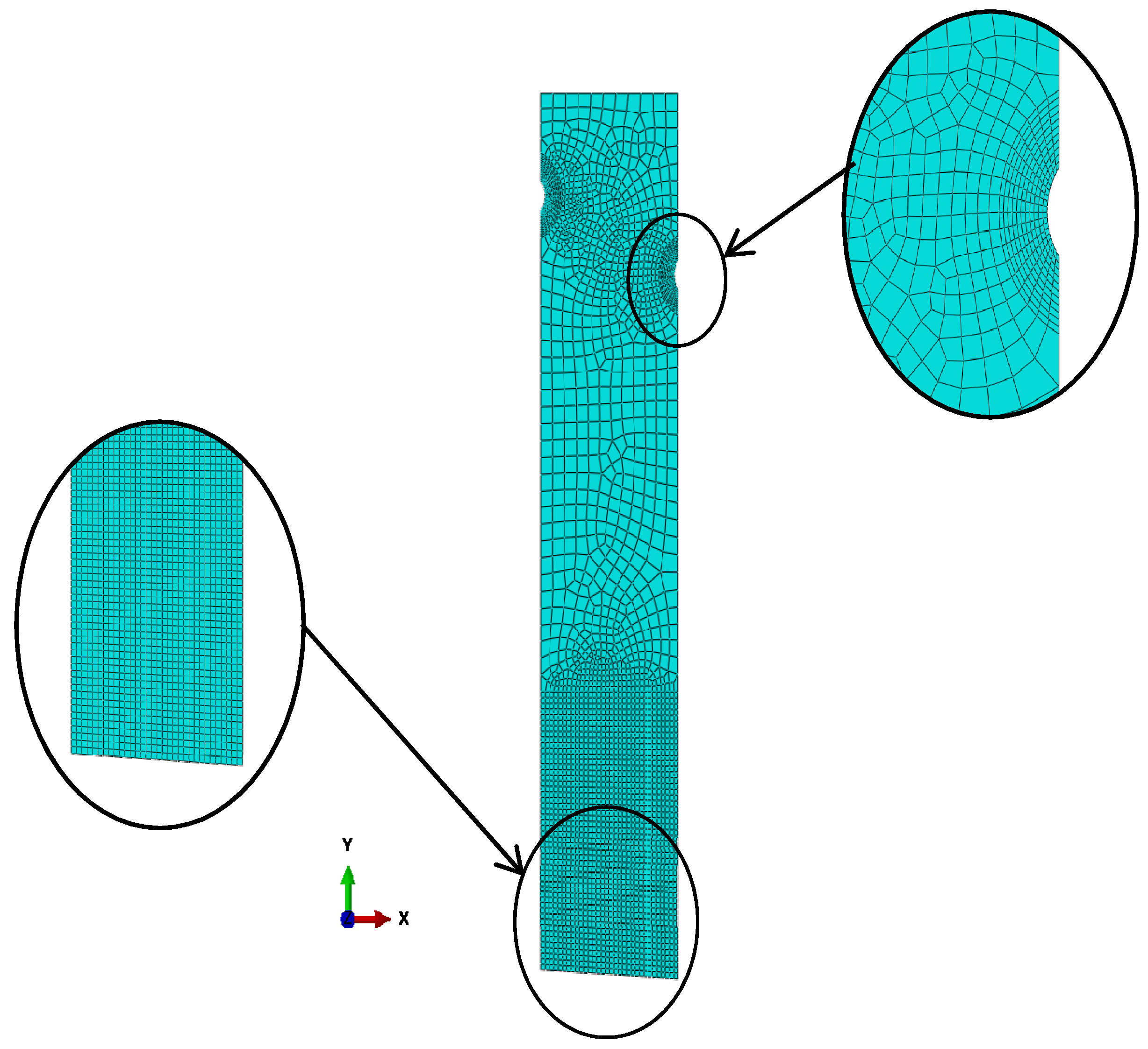
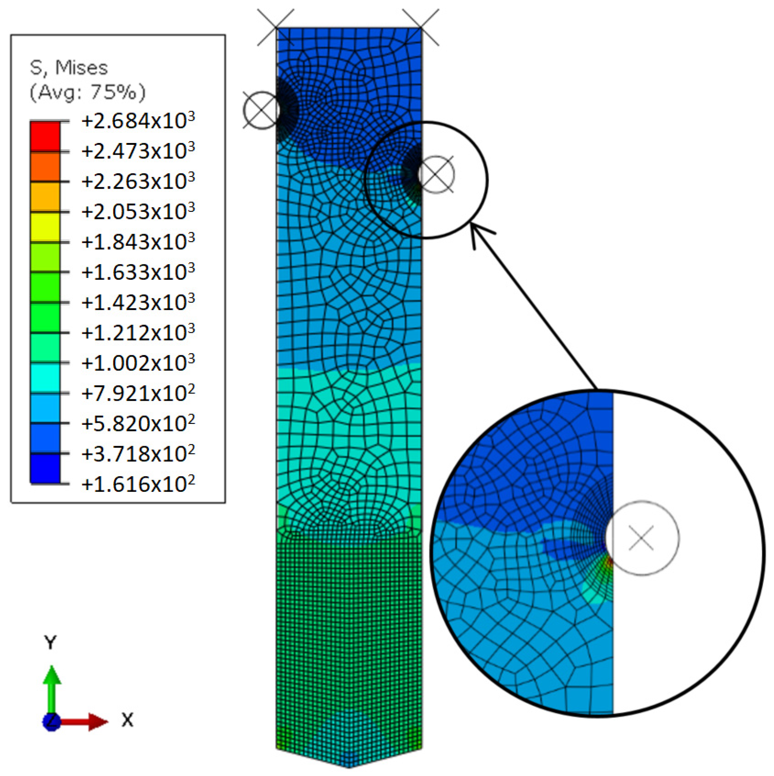
3.2.2. Associated 3D Model

Moreover, as this study mainly focuses on the fixing of the tool, a preliminary 3D model of the upper part of the punch has been built in order to evaluate the accuracy of the initial 2D simulations.
This model (see Figure 13a) utilizes a detailed design of the punch meshed with tetrahedral elements, the same material properties, boundary conditions, and load as the 2D model.
The 3D model gave similar results to the initial 2D model in the areas of interest (near the holes) in compression (Figure 13b) and in tension (Figure 13c), so 2D models were chosen to test some potential improvements.

4. Discussion

4.1. First Improvement of the Tool

In order to improve the lifespan of the punch, two issues were discussed. The first one was in relation to the shape of the cutting edge of the tool. A slight increase in the gap between the tool and the matrix was suggested with reference to previous studies [1,2,3], and a convex shape was proposed with reference to Singh et al.’s study [19], which showed that a convex cutting edge with an angle of 22.5° results in minimal radial deformation for punches compared to flat or inclined cutting edges.
Following this suggestion, a numerical analysis was carried out using ABAQUS. As expected, the results (see Figure 14) showed a reduction in the stress on the cutting edges during compression.

4.2. Second Improvement of the Tool

The second issue discussed was the fixture position. In fact, most of the previous studies focused on the cutting part of the tool and the upper part is not described [8,9,12]. In many cases, the studies exploit a cylindrical punch with an external shoulder [2,7,18,19], but this geometry is not applicable in our case. The study from Cheung et al. [14] utilizes a flat punch without defining precisely how it is fixed to the system. Considering this context, we decided to perform a dedicated study to improve the design of the initial fixing. The improvements in the test consisted of replacing the pins with a single pin in the center of the punch to reduce the maximum stress (illustrated in Figure 15). This modification generated a larger contact surface between the pin and the tool, thus a smaller stress in tension.
To find the maximum permissible diameter dmax without exceeding the elastic limit in compression, the following Formula (3) was used:
Re_punch = Fcutting/Amin,
where:
  • Amin = e (𝑤 − dmax) is the minimum area of the punch;
  • Fcutting = 20 000 is the cutting force calculated previously in N;
  • Re_punch = 2500 is the elastic limit of the punch in MPa;
  • 𝑤 = 15.75 is the width of the punch in mm;
  • e = 0.9 is the thickness of the punch in mm.
The maximum value of the diameter was therefore dmax = 7.03 mm.
To find the optimal value of the diameter, numerical analyses were conducted on diameters of 2, 3, 4, 5, 6 and 7 mm for compression and tension.
The results of Table 4 show that, as the diameter of the pinhole increased, there was a decrease in tensile stress and an increase in compressive stress. The goal was to find a compromise between the two constraints. First, and to ensure that our compressive stress did not reach 2500 MPa, we studied the diameters giving a compressive stress less than 2000 MPa, i.e., diameters ranging from 2 to 4 mm. Subsequently, since at this level the compressive stress varies little with respect to the tensile stress, the diameter with the minimum tensile stress, i.e., 4 mm, was chosen (see Figure 16 and Figure 17).
To expand the study, different pinhole shapes were tested in order to really optimize the tool performance. Other than the round shape, numerical analyses were performed in both compression and tension for two different shapes, a square hole (see Figure 18 and Figure 19) and an oblong hole (see Figure 20 and Figure 21). Each dedicated FE analysis was conducted with specific partitions in order to have only quadratic elements around the hole.
The results in Table 5 show that the round configuration is optimal in terms of compression and traction. The round pinhole has a compressive stress slightly greater than that present in the oblong case, but its tensile stress is much lower than that of the oblong configuration, whereas the square configuration has a much higher stress in both compression and tension.
As a result of this study, the round shape has been selected as a new design for the punch and the punch holder, with satisfactory results in the production process. The first tests show a significant improvement, as the fatigue life of the punch is approximately ten times greater compared to the initial configuration.

5. Conclusions

This paper presents a common production problem encountered in industry, especially as far as the punching process is concerned in metal forming. It mainly discusses the effect of how the punch is fixed in the punch holder.
Based on a real industrial case, numerical analysis using ABAQUS showed that an improved fixing method could generate less stress on the pinhole and, therefore, increase the lifespan of the tool. A centered pin in a round pinhole, with an optimal diameter found by calculation and observations, could thus advantageously replace an eccentric fixture. The stress was reduced by 36%. In addition, a new shape for the cutting edge of the punch was introduced, helping to reduce the stress by 5.5%.
In future work, it would be interesting to investigate different types of materials for the tool.

Author Contributions

Numerical investigation, M.S., V.C. and E.R.A.; experimental investigation, M.S.; writing, M.S. and M.P.; supervision, M.P.; funding acquisition, M.P. All authors have read and agreed to the published version of the manuscript.

Funding

This research received no external funding.

Institutional Review Board Statement

Not applicable.

Informed Consent Statement

Not applicable.

Data Availability Statement

Statement excluded.

Acknowledgments

Thanks to CGR International for its technical support.

Conflicts of Interest

The authors declare no conflict of interest.

References

  1. Uddeholm and SSAB. Tooling Solutions for Advanced High Strength Steels, Selection Guidelines. 2008. pp. 18–23. Available online: https://www.ssab.ru/-/media/files/en/docol/334en-docol-tooling-solutions-for-advanced-high-strength-steels.pdf?m=20210122120609 (accessed on 14 November 2021).
  2. Tekiner, Z.; Nalbant, M.; Gürün, H. An experimental study for the effect of different clearances on burr, smooth-sheared and blanking force on aluminum sheet metal. Mater. Des. 2006, 27, 1134–1138. [Google Scholar] [CrossRef]
  3. Gréban, F. Découpabilité du Cuivre et des Alliages Cuivreux. Ph.D. Thesis, University of Franche-Comté, Besançon, France, 2006. [Google Scholar]
  4. Picas, I.; Hernandez, R.; Casellas, D.; Valls, I. Strategies to increase the tool performance in punching operations of UHSS. In Proceedings of the IDDRG, Graz, Austria, 31 May–2 June 2010. [Google Scholar]
  5. Hambli, R. Etude Expérimentale, Numérique et Théorique du Découpage des Tôles en vue de L’optimisation du Procédé. Ph.D. Thesis, ENSAM of Angers, Angers, France, 1996. [Google Scholar]
  6. Falconnet, E.; Chambert, J.; Makich, H.; Monteil, G.; Picart, P. Analyse de sensibilité d’un modèle d′usure de poinçon lors du découpage d’alliages cuivreux. In Proceedings of the Congrès Français de Mécanique, Besançon, France, 29 August–2 September 2011. [Google Scholar]
  7. Gürün, H.; Göktaş, M.; Guldas, A. Experimental Examination of Effects of Punch Angle and Clearance on Shearing Force and Estimation of Shearing Force Using Fuzzy Logic. Trans. Famena 2016, 40, 19–28. [Google Scholar] [CrossRef] [Green Version]
  8. Kurniawan, Y.; Mahardika, M.; Suyitno. Effect of punch velocity on punch force and burnish height of punched holes in punching process of pure titanium sheet. J. Phys. Conf. Ser. IOP Sci. 2020, 1430, 12053. [Google Scholar] [CrossRef]
  9. Touache, A. Contribution à la Caractérisation et à la Modélisation de L’influence de la Vitesse et de la Température sur le Comportement en Découpage de Tôles Minces. Ph.D. Thesis, University of Franche-Comté, Besançon, France, 2006. Available online: https://tel.archives-ouvertes.fr/tel-00132399/ (accessed on 14 November 2021).
  10. Johnson, W.; Slater, R.A.C. A Survey of the Slow and Fast Blanking of Metals at Ambient and High Temperatures. In Proceedings of the International Conference on Manufacturing Technology (CIRP-ASTME), Ann Arbor, MI, USA, 25–28 September 1967; pp. 825–851. [Google Scholar]
  11. Balendra, R.; Travis, F. Static and dynamic blanking of sheet of varying hardness. Int. J. Mach. Tools Manuf. 1970, 10, 265–275. [Google Scholar] [CrossRef]
  12. Available online: https://www.mate.com/fr/technical-resources/tips-techniques/punching/punch-die-maintenance/factors-affecting-tool-wear/ (accessed on 14 November 2021).
  13. Monteil, G.; Gréban, F.; Roizard, X. In Situ punch wear measurement in a blanking tool, by means of thin layer activation. Wear 2008, 265, 630–632. [Google Scholar] [CrossRef]
  14. Cheung, C.F.; Lee, W.B.; Chiu, W.M. An investigation of tool wear in the dam-bar cutting of integrated circuit packages. Wear 2000, 237, 274–282. [Google Scholar] [CrossRef]
  15. Won, C.; Lee, S.; Seo, J.; Park, S.H.; Yoon, J. Stripping failure of punching pin in GPa-grade steels. Int. J. Adv. Manuf. Technol. 2019, 94, 73–83. [Google Scholar] [CrossRef]
  16. He, B. Failure and Protective Measures on Punch & Die for Cold Extrusion. In Proceedings of the 2012 International Conference on Computer Application and System Modeling, ICCASM, Taiyuan, China, 27–29 July 2012. Advances in Intelligent Systems Research. [Google Scholar] [CrossRef] [Green Version]
  17. Haddadou, M.; Aichoun, M. Etude et Conception de Deux Outils de Découpage-Poinçonnage et de Pliage Pour Clapet Air Bruleur. Ph.D. Thesis, University Mouloud Mammeri de Tizi-Ouzou, Tizi-Ouzou, Algeria, 2014. Available online: https://sociale.ummto.dz/handle/ummto/6041 (accessed on 14 November 2021).
  18. Makich, H. Etude Théorique et Expérimentale de L’usure des Outils de Découpe: Influence sur la Qualité des Pièces Découpées. Ph.D. Thesis, University of Franche-Comté, Besançon, France, 2011. Available online: https://tel.archives-ouvertes.fr/tel-01068646 (accessed on 14 November 2021).
  19. Singh, U.P.; Streppel, A.H.; Kals, H.J.J. Design study of the geometry of a punching/blanking tool. J. Mater. Proc. Tech. 1992, 33, 331–345. [Google Scholar] [CrossRef] [Green Version]
Figure 1. Initial shape of the punch tool.
Applsci 11 11013 g001
Figure 2. Punching system.
Applsci 11 11013 g002
Figure 3. Fracture after 3000 cycles.
Applsci 11 11013 g003
Figure 4. Dino-Lite digital microscope.
Applsci 11 11013 g004
Figure 5. Dino-Lite digital microscope close-up of the measurements of the punch fractured at the fixing point.
Applsci 11 11013 g005
Figure 6. Alicona optical 3D profilometer for high-resolution measurements.
Applsci 11 11013 g006
Figure 7. Indentations on punch showing a fracture on the fixture. (a) Lower hole, (b) upper hole.
Applsci 11 11013 g007
Figure 8. Indentations on punch showing a fracture on the cutting edge. (a) Lower hole, (b) upper hole.
Applsci 11 11013 g008
Figure 9. Metrology of the tool (a) before fracture, (b) after fracture.
Applsci 11 11013 g009
Figure 10. Meshing of the tool.
Applsci 11 11013 g010
Figure 11. Results of the compression test.
Applsci 11 11013 g011
Figure 12. Results of the tension test.
Applsci 11 11013 g012
Figure 13. 3D model.
Applsci 11 11013 g013
Figure 14. Maximum stress after shape change.
Applsci 11 11013 g014
Figure 15. Punch with a round centered fixation.
Applsci 11 11013 g015
Figure 16. Compression results with a 4 mm diameter pinhole.
Applsci 11 11013 g016
Figure 17. Tension results with a 4 mm diameter pinhole.
Applsci 11 11013 g017
Figure 18. Square hole dimensions and partitions.
Applsci 11 11013 g018
Figure 19. Maximum stress for the square pinhole, (a) in compression, (b) in tension.
Applsci 11 11013 g019
Figure 20. Oblong hole dimensions and partitions.
Applsci 11 11013 g020
Figure 21. Maximum stress for the oblong pinhole, (a) in compression, (b) in tension.
Applsci 11 11013 g021
Table 1. Chemical composition of the punch.
CCrMoWCoV
1.284.05.06.4-3.1
Table 2. Mechanical properties of the punch.
E (GPa)ρ (g/cm3)νRc (MPa)
23080.32500
Rmc (MPa)Hardness (HRC)Rt (MPa)Rmt (MPa)
33336122703026
Table 3. Measurements of the two holes on the fractured punch.
NameLength
(mm)
Area
(mm2)
Radius
(mm)
Diameter (mm)Angle
(deg.)
AR057.8443.1386.27691.292
AR15.0136.8562.7355.471104.993
Table 4. Numerical results for compression and tension for different diameters.
Diameter (mm)σcmax (MPa)σtmax (MPa)
216392199
317981530
417931043
52037976
62161864
Table 5. Maximum stress for all shapes.
ShapeMax Stress in Compression (MPa)Max Stress in Tension
(MPa)
Round17931043
Square18792551
Oblong17721318
Publisher’s Note: MDPI stays neutral with regard to jurisdictional claims in published maps and institutional affiliations.

