Article

Laboratory- and Semi-Industrial-Scale Thermomechanical Processing of TRIP-Aided Steel with Acicular Ferrite

Department of Engineering Materials and Biomaterials, Faculty of Mechanical Engineering, Silesian University of Technology, 18A Konarskiego Street, 44-100 Gliwice, Poland
*
Author to whom correspondence should be addressed.
Appl. Sci. 2021, 11(20), 9512; https://doi.org/10.3390/app11209512
Submission received: 23 August 2021 / Revised: 11 October 2021 / Accepted: 12 October 2021 / Published: 13 October 2021
(This article belongs to the Special Issue Progress in Advanced High-Strength Steels)

Abstract

:

Featured Application

The automotive industry and specific autobody parts.

Abstract

The modification of the deformation and cooling methods resulting in the obtainment of acicular ferrite promotes an increase in the proportion of retained austenite (RA) and a corresponding increase in mechanical properties in Si-Al TRIP-aided steel. The effect of controlled thermomechanical processing in laboratory- and semi-industrial scales on the possibility of obtaining acicular ferrite and a high fraction of retained austenite was investigated. The steel was hot deformed in three steps: at 1050, 900 and 750 °C to introduce dislocations into the hot-deformed pancake austenite. Next, slow cooling in a ferritic transformation region was performed, followed by isothermal holding of steel at 450 °C. The interrupted tensile tests at the strain levels of 5, 10 and 15% were performed to investigate the mechanical properties response and the stability of the obtained retained austenite. Light and scanning electron microscopy, XRD and EBSD analyses were performed to assess microstructural features. The produced material showed a multiphase microstructure containing acicular ferrite and 10% of retained austenite. The microstructures obtained in both production methods were slightly different due to high temperature inertia in the semi-industrial process.

1. Introduction

The most important structural constituent of multiphase TRIP (TRansformation Induced Plasticity) [1] steels is retained austenite (RA). Its metastability enables the occurrence of strain-induced martensitic transformation (SIMT) [2], which increases strain hardening rate and strongly influences the steel plasticity [3]. The stability of RA depends on many factors, including phase morphology [4,5], localization [6], size [7,8] and carbon content [9,10,11].
Numerous studies [10,12] have proved that a full description of the SIMT [13] requires taking into account the amount and morphology of other structural constituents [14]. Initially, attention was drawn to the possibility of the partial replacement of ferrite with a polygonal morphology by an acicular morphology. For high strength low-alloy steels, an acicular ferrite microstructure ensures a very good balance of strength and toughness [15]. Zarei-Hanzaki et al. [16] found that the modification of the cooling method resulting in obtaining acicular ferrite promotes an increase in the proportion of retained austenite in 0.22 C-1.55 Mn-1.55 Si-Nb steel from 9.5 to 12.3%. The formation of acicular ferrite causes greater fragmentation of supercooled austenite grains and promotes the geometric stabilization of this phase. Similar results of the effect of acicular ferrite on increasing a fraction of retained austenite were obtained in steels with Nb micro additions by Timokhina et al. [17] and Pereloma et al. [18].
Bainite morphology also has a significant influence on the stability of the retained austenite [19]. Timokhina et al. [20] and Zhuang and Wu [21] showed that the optimal combination of mechanical properties is obtained when bainite has a granular morphology. Fine islands of austenite between the plates or grains of bainitic ferrite have optimal conditions for carbon enrichment while holding the steel in the bainite range. This is caused by the short carbon diffusion path and the small dimensions of the γ phase areas, which favor the stabilization of austenite. Equally important is the vicinity of the harder bainitic ferrite plates, which limit the transfer of deformation to the austenite. In the preliminary stage the strain is located in the ferrite. For this reason, the martensitic transformation first takes place in grains located in the γ phase matrix, and the deformation of austenite located in the granular bainite takes place at a later stage of deformation, ensuring a gradual martensitic transformation [12,22,23].
The development of multi-phase steels in recent years is associated with the partial or complete replacement of silicon [24] by Al or P [25,26,27]. The study of their impact on a fraction of retained austenite obtained under different heat treatment conditions and the mechanical stability of the γ phase during cold deformation is also of scientific interest. Both the solutions related to the use of aluminum and phosphorus [28] have a negative impact on the factors related to the stability of the retained austenite or the mechanical properties of steel [29,30]. The complete replacement of silicon with aluminum causes a significant reduction in the solid solution hardening and a reduction in the strength properties of the steel. Moreover, the high content of aluminum raises the Ms (martensitic start) [31] temperature of the retained austenite (RA), which may cause a partial transformation of this phase into martensite during the cooling of the steel from the isothermal temperature in the bainite range (fresh martensite is formed). Increasing the phosphorus concentration to about 0.1% has a positive effect on increasing the strength properties and mechanical stabilization of the retained austenite, but is usually associated with an increase in the brittleness of the steel.
Producing a multiphase structure with an appropriate proportion, distribution and morphology of individual structural constituents requires appropriate control of the chemical composition of steel and the processes taking place during hot-working as well as controlled cooling under conditions adapted to the kinetics of phase transformations of plastically deformed supercooled austenite.
For this reason, the aim of the work was to produce a micro alloyed TRIP-aided steel containing acicular ferrite, which contributes to substantial mechanical properties in the semi-industrial thermomechanical rolling process. The next step was devoted to investigating the structural phenomena occurring during the SIMT. These phenomena are determined by the fragmentation of the prior austenite structure and several-step cooling under conditions of the controlled progress of supercooled austenite phase transformations.

2. Materials and Methods

Material containing 0.24%C, 1.55%Mn, 0.87%Si, 0.40%Al, 0.004%S, 0.010%P, 0.034%Nb and 0.023%Ti (in wt.%) was used in this study. The steel was designed to obtain a ferritic–bainitic structure with retained austenite. It is characterized by an increased content of Mn, Si and Al. The carbon content is limited to 0.24% to ensure good weldability, and at the same time high strength properties and optimal enrichment of the retained austenite with this element. Manganese acts as an austenite stabilizer and lowers the temperature of cementite precipitation. The Si concentration was lowered—from the most used 1.5% in TRIP steels—to 0.87%, and the rest was replaced by adding 0.4% Al. The purpose of the Nb and Ti micro additions was to produce carbides, nitrides and carbonitrides during hot-working. Due to the precipitates, the possibility of producing fine-grained structures is expected.
The 25 kg alloy was melted in a VSG-50 vacuum furnace (Balzers). The material was cast in argon atmosphere and forged to the form of 20 × 220 mm flat bars. The forging temperature range was 900–1200 °C. Next, the steel was roughly rolled in four passes to the thickness of 4.5 mm in the temperature range 900–1200 °C.
After the initial production process, the material was subjected to pilot, laboratory-scale thermomechanical processing simulating the final process. For this purpose, the Gleeble 3800 by DSI was used. This treatment was composed of two major steps:
Hot compression simulating the rolling process (samples 15 × 20 × 35 mm)
  • 1st compression. T—1050 °C, ε—0.28,
  • 2nd compression. T—900 °C, ε—0.30,
  • 3rd compression. T—750 °C, ε—0.22.
Controlled cooling with two isothermal holding steps:
  • Fast cooling from 750 °C to 650 °C (15 °Cs−1), performed to start the ferritic transformation at a high cooling rate and relatively low temperature for the purpose of producing acicular ferrite [16,32].
  • Slow cooling to 580 °C (1.4 °Cs−1)—1st step of stabilization. The timing was chosen to maximize a ferrite fraction and thus C redistribution.
  • Fast cooling to 450 °C (40 °Cs−1)—to avoid pearlite transformation,
  • Isothermal holding for 600 s—2nd step of stabilization,
  • Final cooling to room temperature (0.5 °Cs−1).
To obtain strongly deformed pancake austenite, the finish temperature of the hot-working was set at 750 °C. The cooling parameters were selected based on CCT (continuous cooling transformation) diagrams.
After conducting pilot tests at the laboratory scale, semi-industrial thermomechanical processing was applied based on the same process parameters (3 passes with ε: 0.28, 0.30, 0.22, respectively). The rolling was conducted in the semi-industrial line, the detailed characteristics of which is described in [33]. For the rolling, the D550 two-high reversing hot rolling mill with a roll diameter of 550 mm and a roll barrel length of 700 mm was used. The final material was subjected to an interrupted tensile test using Zwick Z/100. The samples used were 2 mm thick, 12.5 mm wide, and the gauge length was 50 mm. The performed tensile tests were stopped at 5, 10, 15% strain, and finally the full tensile tests to the fracture of the sample were applied.
The following mechanical characteristics were calculated:
  • Work hardening rate using the true stress and true strain [34]:
    σ = F S = σ p ( 1 + ε p ) ,   MPa
    ε = ln ( 1 + ε p )
    where: σ—true stress, ε—true strain, F—load, S—true cross-section of the sample, σp—engineering stress and εp—engineering strain.
  • Work hardening exponent using the following equation [17]:
    n = ε d σ σ d ε = d ( l o g σ ) d ( l o g ε )
After both variants of thermomechanical processing and interrupted tensile tests, samples were subjected to metallographic tests. The light and scanning electron microscopy were performed using Leica MEF 4A and Supra 25 microscopes, respectively. The microscopic investigations were performed for microstructure and morphology characterization. The tensile-tested specimens for further investigations were cut from the near-neck areas. The samples were prepared according to standard metallographic procedures (cutting, grinding (papers P220 to P2000), polishing (polishing pastes 3, 1 μm, and 0.2 μm colloidal silica) and etching using nital). X-ray diffraction (XRD) (using a Panalytical X’Pert Pro MPD diffractometer and a copper-anode lamp (λKα = 0.154 nm)) and electron backscatter diffraction (EBSD) (using a high-resolution Scanning Electron Microscope (SEM) FEI Inspect F) analyses were performed to characterize the RA fraction in the microstructure. The fraction of RA was calculated using a Rietveld method [24,35] and to determine the C content in austenite, the following equation was used [36]:
a γ = 3.579 + 0.033 C γ
where: a γ —lattice parameter of austenite, C γ —carbon content in austenite (wt.%).

3. Results

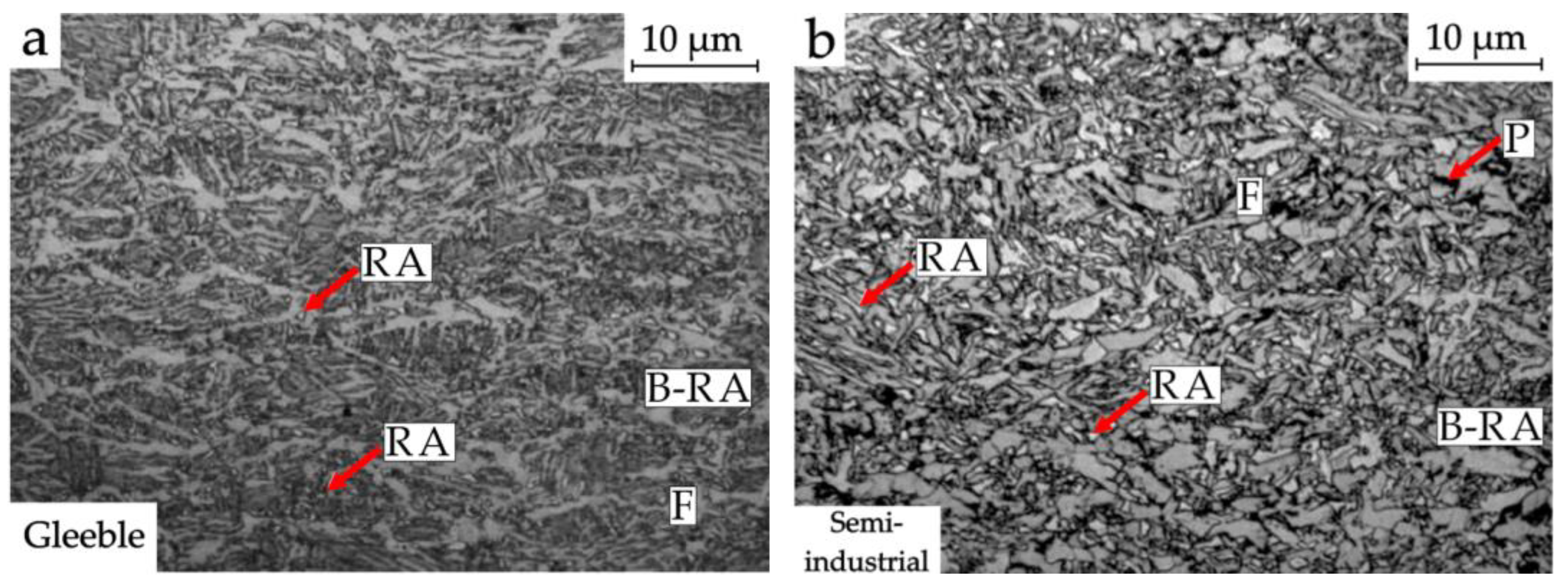
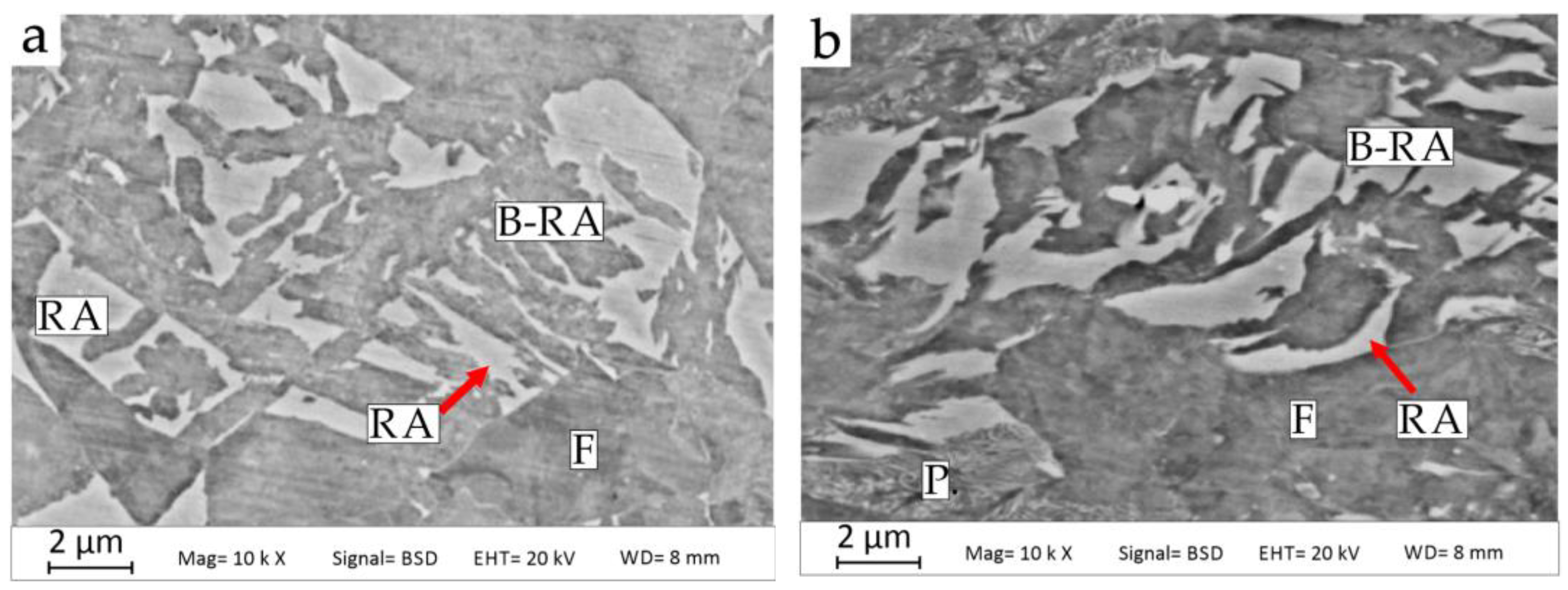
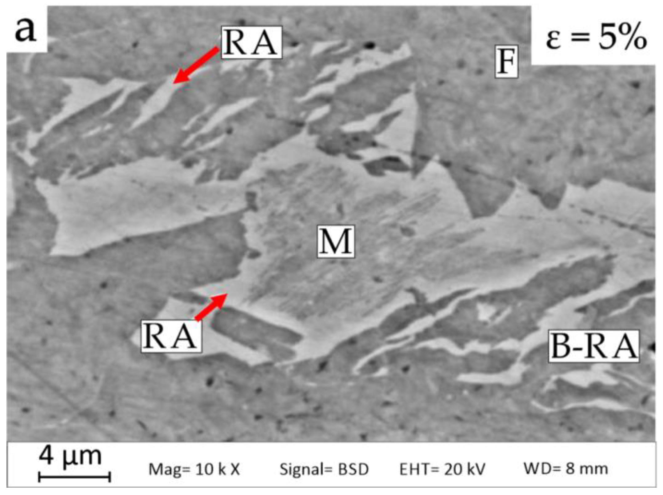
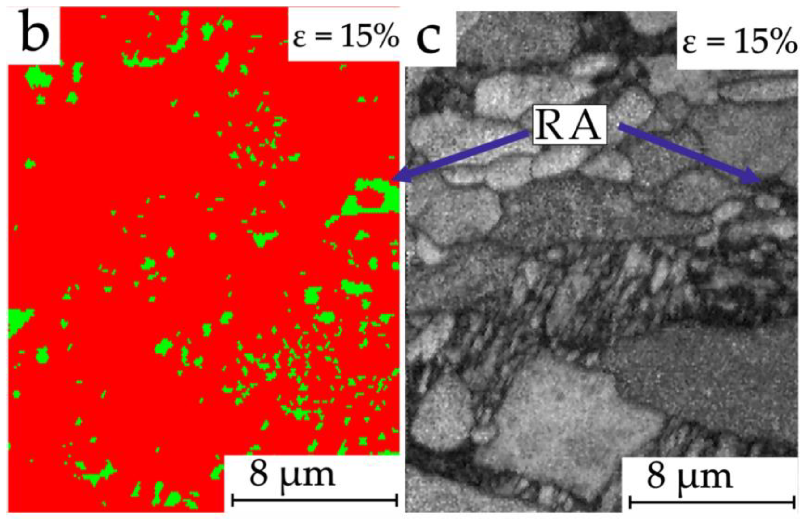
3.1. Microstructural Characterization and Stability of RA

The performed thermomechanical processing realized using the Gleeble simulator provided the microstructures composed of bainite, acicular ferrite and RA (Figure 1). The semi-industrial process characterized by less precise control of temperature–time parameters (greater temperature inertia) resulted in the formation of an additional small fraction of pearlite in the microstructure (Figure 1b and Figure 2b).
The RA in both cases is fine and evenly distributed. The majority of the RA is in a form of fine grains or elongated layers at the interfacial boundaries of acicular ferrite and bainitic ferrite, or it is located inside bainitic areas (Figure 2). The austenite deformation conditions below the recrystallization finish temperature of this phase favor the refinement of the ferritic matrix grains. Therefore, a significant part of the RA occurs in this phase. The retained austenite grains located in ferrite tend to elongate in the direction of plastic flow, as evidenced by an aspect ratio ~1.4.
Comparing the steel microstructures obtained after the semi-industrial rolling and in the Gleeble simulator, it can be concluded that they generally show good agreement. The differences may be caused by the different cooling rate in individual stages of sample cooling, which is constant (in individual temperature ranges) in laboratory conditions, and changes during the cooling of sheets in the air and immersion cooling. The laboratory-scale production process resulted in obtaining ~10% of the RA in the microstructure with a carbon content above 1.5 wt.% (Table 1). The pearlite formation in case of semi-industrial production process didn’t affect the RA fraction. However, there is a significant reduction in the C content (~1 wt.%) in this phase.
During tensile deformation, the largest retained austenite grains distributed in the ferrite are transformed into strain-induced martensite first (Figure 3a). The transformation of grains present in ferrite progresses with the increase of strain up to 10%. The fine-plate martensite formed under these conditions covers almost the entire surface of the larger grains, while the finer, blocky grains and thin layers of RA do not transform.
After increasing the strain value to 15% (Figure 3b,c), the fraction of retained austenite decreases to about 4% (Table 1). Figure 3 shows that the martensitic transformation is subject to layered areas with a width of about 1 µm, located within the bainitic ferrite laths, whereas the RA films retain mechanically stability. The γ phase is most often in the form of a shell around the formed martensite or small areas in the bainitic ferrite. The amount of untransformed γ phase after sample breaking is about 2.5%. The relatively rapid transformation of austenite into martensite in the initial stage of deformation results from the carbon content (1.08 wt.%) in the retained austenite (Table 1).

3.2. Mechanical Properties

The summarized mechanical properties of the investigated material are shown in Table 2. The yield point of 470 MPa is caused by a large proportion of fine-grained ferrite. The rapid transformation of the RA into martensite is reflected as a sudden increase in the value of the true stress in the initial stage of deformation (Figure 4). This leads to a relatively high value of Ultimate Tensile Strength (UTS) = 690 MPa, with the corresponding Ultimate Elongation (UEI) at a level of 15.6%.
The maximum value of the strain hardening exponent (Figure 4) is n = 0.2 for a strain value of about 0.05, but it decreases with its increase. This proves the relatively low stability of retained austenite, which is confirmed by the low concentration of C in this phase, amounting to 1.07%. The transformation of blocky grains has a large impact on the strain hardening rate. The martensitic transformation takes place gradually, but the initial fraction of the γ phase determines the relatively small fraction of transformed austenite (newly formed martensite), which influences the continuous reduction in the value of the instantaneous strain hardening exponent of about 0.06.
The results of the research on the mechanical stability of the retained austenite expressed by the kγ value is shown in Figure 5. The value of the kγ parameter depends on the slope of a line representing the logarithmic change of the retained austenite fraction as a function of true strain. The tested steel shows kγ at the level of 3.67. This value is underestimated due to the presence of pearlite in the microstructure and thus a reduction in the carbon content of the austenite.

4. Discussion

Steels containing acicular ferrite have a great potential to improve mechanical properties [37,38] by grain refinement, higher dislocation density or controlled precipitation. What is more, the toughness provided by acicular ferrite is considerably higher than that of bainitic ferrite due to a higher density of high angle grain boundaries [15]. Results of previous studies indicate that the introduction of intragranular nucleation sites and the suppression of bainitic ferrite laths lengthening are identified as the two key requirements for the occurrence of acicular ferrite [15]. Austenite deformation is a critical factor as it introduces the high density of dislocations that act as nucleation sites. It is accepted and proved that the acicular ferrite transformation is a transitional state between the formation of globular ferrite and bainite. The optimal cooling rate to achieve a sufficient fraction of acicular ferrite depends strongly on the production process and chemical composition of given steel. As a result, the very wide range of cooling rates is described in the literature as being suitable for acicular ferrite (from 6 to 3000 °Cs−1) [32]. In the current case, an increased cooling rate (15 °Cs−1) was applied at the beginning of the ferritic transformation to enable the formation of acicular ferrite. However, in a later step, cooling was much slower to maximize a ferrite fraction and thus the austenite stabilization. Using combined cooling methods enabled both above requirements to be obtained. In previous studies [13] the same steel was heat treated in similar conditions but with elevated hot-working temperatures (finishing rolling at 850 °C, fast cooling to 700 °C and slow cooling to 650 °C). The lower dislocation density caused by plastic deformation at the higher temperature and successive phase transformations performed at higher temperatures caused a globular ferrite formation and obtaining YS~50 MPa and UTS~35 MPa lower; however, with total elongation 4% higher, caused mainly by the fraction and carbon content in retained austenite.
The application of the finish hot-working temperature of 750 °C (lower than the recrystallization temperature) introduces the needed dislocations and affects the elongation of the ferritic matrix grains in the direction of plastic flow for samples deformed both in the Gleeble simulator and in semi-industrial conditions. In conjunction with slow cooling, it allows the acicular ferrite to be obtained instead of the polygonal one.
The selection of hot working conditions had to take into account the limitations resulting from the rolling of steel in the double-reversible system, which shows significant differences with regard to industrial hot strip rolling in a continuous system, especially in terms of the number of applied deformation steps, strain rate, time intervals between passes, etc. [39]. In conventional C-Mn-Si TRIP steels with a Si concentration of~1.5% or in C-Mn-Si-Al steels with silicon partially replaced by Al, the SIMT occurs rapidly in the initial stage of deformation, which usually affects lower steel plasticity [40,41]. Even in the case of obtaining the total elongation up to 30% in the C-Mn-Si steels, it is most often at the expense of high silicon content [42,43], and in the case of C-Mn-Si-Al steels, the strength properties are lowered [44,45].
A characteristic feature of the investigated steel is a sudden decrease in the strain hardening rate in the initial stage of deformation, which corresponds to the generation of new dislocations and the avoidance of obstacles by dislocations as a result of transverse slip [3]. However, multiphase steels are characterized by several times higher dσ/dε values compared to conventional deep-drawing steels, due to the large portion of bainitic-austenitic islands [39]. The obtained kγ value—3.67 is much lower (kγ~10) than in the case of 0.17 C-1.4 Si-2 Mn steel investigated by Sugimoto et al. [46]. However, in another work [47], Sugimoto et al. indicated stability of retained austenite (0.2 C-1.5 Si-1.5 Mn steel) higher (kγ~2.7) than that one obtained for the investigated steel. All mentioned steels show similar chemical compositions and the difference in the mechanical stability of the RA results mainly from different carbon contents in this phase.
Despite the effectively refined γ phase grains in the investigated steel located in the bainitic islands and at the interfacial boundaries of bainite and acicular ferrite, the initiation of the pearlitic transformation resulted in the lowering of the carbon concentration in the retained austenite to 1.07% and the fraction of this phase to 10%. This is confirmed by the complexity of the structural and technological factors determining the final thermodynamic stability of the γ phase. The precipitation of cementite-forming pearlite resulted in the depletion of the retained austenite in carbon. Therefore, the lack of thermal stability of the largest blocky RA grains (Figure 6) during the final cooling of the steel to room temperature took place leading to the partial martensitic transformation. It is also confirmed by the image obtained using the EBSD technique. The presence of martensite is clearly evidenced by the poor diffraction quality of this phase resulting in dark areas in Figure 6a. This is due to the highest density of defects in the crystal structure of martensite [48,49]. The presence of RA in the outer grain zone of the grain proves that the boundary areas of the austenite are more enriched with carbon [4,5].

5. Conclusions

The work concerns a study of thermomechanical processing of 0.24 C-0.9 Si-0.4 Al TRIP steel in laboratory- and semi-industrial scales. The possibility for obtaining acicular ferrite and corresponding mechanical properties during interrupted tensile tests were investigated. The main findings of the present study are as follows:
  • Accelerated controlled cooling after plastic deformation of the austenite combined with the realization of the ferritic transformation in a reduced temperature range (from 650 to 580 °C) allows acicular ferrite to be obtained in the microstructure.
  • Both manufacturing methods allowed RA amounts at a level of about 10% to be obtained. However, pearlitic transformation was initiated due to the more difficult temperature control associated with the semi-industrial process, which consumed some carbon and thus decreased the stability of RA produced in this way,
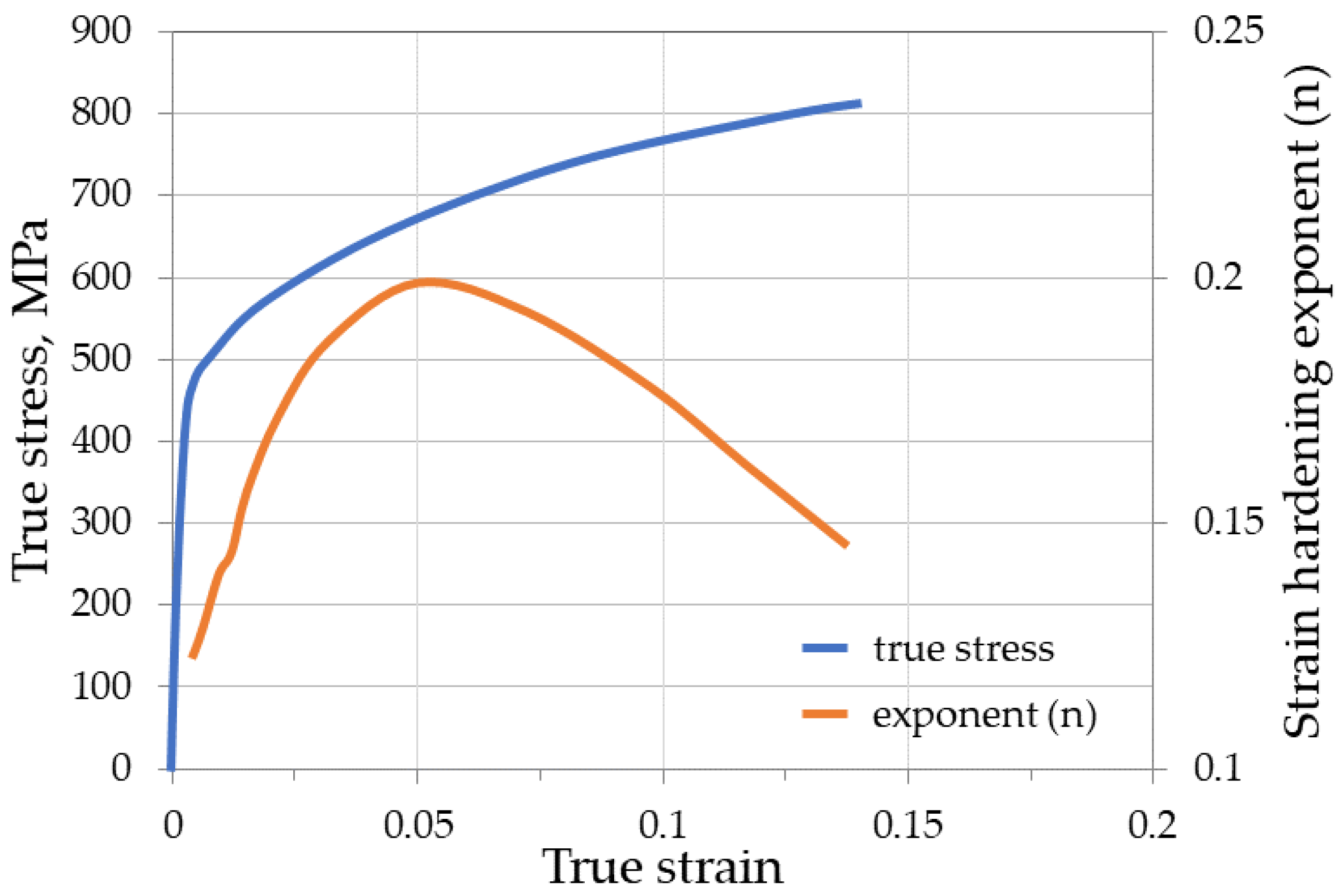
  • The steel produced here has the following properties: YS0,2~472 MPa, UTS~690 MPa and UEI~15.6%, and the strain hardening exponent peak (0.2) at a strain of 0.05. The YS0,2 and UTS are 70 and 40 MPa higher compared to steel containing polygonal ferrite,
  • Insufficient enrichment of RA in carbon leads to the intense martensitic transformation in an early stage of deformation (confirmed by the strain hardening peak) and thus lowered plasticity,
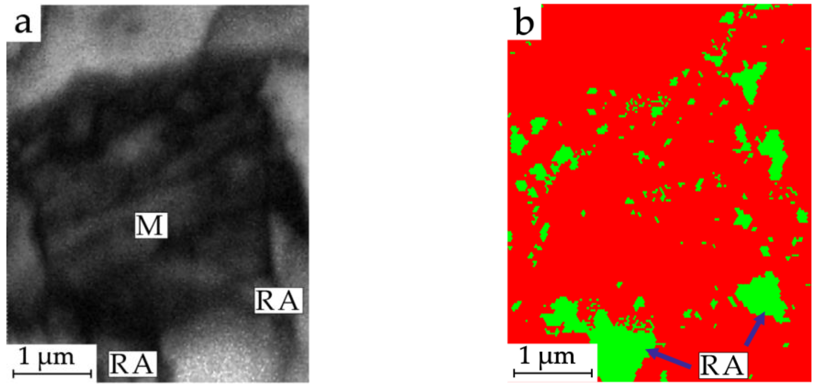
  • The martensitic transformation starts in the centers of the largest grains and affects their gradual fragmentation separating regions of higher stability. This leads to the formation of RA-M islands.

Author Contributions

Conceptualization, A.G. and A.S.; methodology, A.G.; validation, A.G. and A.S.; formal analysis, A.G.; investigation, A.S.; resources, A.G.; data curation, A.S.; writing—original draft preparation, A.S.; writing—review and editing, A.G.; visualization, A.S.; supervision, A.G.; project administration, A.G. and A.S. All authors have read and agreed to the published version of the manuscript.

Funding

The financial support of the Silesian University of Technology, Poland, is gratefully acknowledged, grant no. 10/010/BKM21/1049.

Institutional Review Board Statement

Not applicable.

Informed Consent Statement

Not applicable.

Data Availability Statement

Not applicable.

Acknowledgments

Co-financed by the European Union through the European Social Fund (grant POWR.03.05.00-00-Z305).

Conflicts of Interest

The authors declare no conflict of interest.

References

  1. Valdes-Tabernero, M.A.; Celada-Casero, C.; Sabirov, I.; Kumar, A.; Petrov, R.H. The Effect of Heating Rate and Soaking Time on Microstructure of an Advanced High Strength Steel. Mater. Charact. 2019, 155, 109822. [Google Scholar] [CrossRef] [Green Version]
  2. Sun, S.; Cai, M.; Ding, H.; Huang, H.; Pan, H. Deformation Mechanisms of a Novel Mn-Based 1 GPa TRIP/TWIP Assisted Lightweight Steel with 63% Ductility. Mater. Sci. Eng. A 2021, 802, 140658. [Google Scholar] [CrossRef]
  3. Bleck, W. Using the TRIP Effect—The Dawn of a Promising Group of Cold Formable Steels; Ghent University: Ghent, Belgium, 2002; pp. 13–23. [Google Scholar]
  4. Zhao, L.; van Dijk, N.H.; Brück, E.; Sietsma, J.; van der Zwaag, S. Magnetic and X-Ray Diffraction Measurements for the Determination of Retained Austenite in TRIP Steels. Mater. Sci. Eng. A 2001, 313, 145–152. [Google Scholar] [CrossRef]
  5. Sherif, M.Y.; Mateo, C.G.; Sourmail, T.; Bhadeshia, H.K.D.H. Stability of Retained Austenite in TRIP-Assisted Steels. Mater. Sci. Technol. 2004, 20, 319–322. [Google Scholar] [CrossRef] [Green Version]
  6. Grajcar, A.; Kwaśny, W.; Zalecki, W. Microstructure–Property Relationships in TRIP Aided Medium-C Bainitic Steel with Lamellar Retained Austenite. Mater. Sci. Technol. 2015, 31, 781–794. [Google Scholar] [CrossRef]
  7. Iung, T.; Drillet, J.; Couturier, A.; Olier, C. Detailed study of the transformation mechanisms in ferrous TRIP aided steels. Steel Res. 2002, 73, 218–224. [Google Scholar] [CrossRef]
  8. Wang, J.; Van Der Zwaag, S. Stabilization Mechanisms of Retained Austenite in Transformation-Induced Plasticity Steel. Metall. Mater. Trans. A 2001, 32, 1527–1539. [Google Scholar] [CrossRef]
  9. Grajcar, A.; Płachcińska, A.; Topolska, S.; Kciuk, M. Effect of Thermomechanical Treatment on the Corrosion Behaviour of Si- and Al-Containing High-Mn Austenitic Steel with Nb and Ti Micro-Additions. Mater. Tehnol. 2015, 49, 889–894. [Google Scholar] [CrossRef]
  10. Mukherjee, M.; Mohanty, O.N.; Hashimoto, S.; Hojo, T.; Sugimoto, K. Strain-Induced Transformation Behaviour of Retained Austenite and Tensile Properties of TRIP-Aided Steels with Different Matrix Microstructure. ISIJ Int. 2006, 46, 316–324. [Google Scholar] [CrossRef] [Green Version]
  11. Zhou, W.; Hou, T.; Zhang, C.; Zhong, L.; Wu, K. Effect of Carbon Content in Retained Austenite on the Dynamic Tensile Behavior of Nanostructured Bainitic Steel. Metals 2018, 8, 907. [Google Scholar] [CrossRef] [Green Version]
  12. Timokhina, I.B.; Hodgson, P.D.; Pereloma, E.V. Effect of Microstructure on the Stability of Retained Austenite in Transformation-Induced-Plasticity Steels. Metall. Mater. Trans. A 2004, 35, 2331–2341. [Google Scholar] [CrossRef] [Green Version]
  13. Grajcar, A.; Radwański, K. Microstructural Comparison of the Thermomechanically Treated and Cold Deformed Nb-Microalloyed TRIP Steel. Mater. Tehnol. 2014, 48, 679–683. [Google Scholar]
  14. Zhao, J.; Jiang, Z. Thermomechanical Processing of Advanced High Strength Steels. Prog. Mater. Sci. 2018, 94, 174–242. [Google Scholar] [CrossRef]
  15. Zhao, H.; Wynne, B.P.; Palmiere, E.J. Conditions for the Occurrence of Acicular Ferrite Transformation in HSLA Steels. Mater. Sci. 2018, 53, 3785–3804. [Google Scholar] [CrossRef] [Green Version]
  16. Zarei-Hanzaki, A.; Yue, S. Ferrite Formation Characteristics in Si-Mn TRIP Steels. ISIJ Int. 1997, 37, 583–589. [Google Scholar] [CrossRef]
  17. Timokhina, I.; Hodgson, P.; Pereloma, E. Effect of Alloying Elements on the Microstructure-Property Relationship in Thermomechanically Processed C-Mn-Si TRIP Steels. Steel Res. 2002, 73, 274–279. [Google Scholar] [CrossRef]
  18. Pereloma, E.V.; Timokhina, I.B.; Hodgson, P.D. Transformation Behaviour in Thermomechanically Processed C–Mn–Si TRIP Steels with and without Nb. Mater. Sci. Eng. A 1999, 273–275, 448–452. [Google Scholar] [CrossRef]
  19. Zhou, Y.X.; Song, X.T.; Liang, J.W.; Shen, Y.F.; Misra, R.D.K. Innovative Processing of Obtaining Nanostructured Bainite with High Strength—High Ductility Combination in Low-Carbon-Medium-Mn Steel: Process-Structure-Property Relationship. Mater. Sci. Eng. A 2018, 718, 267–276. [Google Scholar] [CrossRef]
  20. Timokhina, I.; Hodgson, P.; Pereloma, E. Effect of Deformation Schedule on the Microstructure and Mechanical Properties of a Thermomechanically Processed C-Mn-Si Transformation-Induced Plasticity Steel. Metall. Mater. Trans. A 2003, 34, 1599–1609. [Google Scholar] [CrossRef] [Green Version]
  21. Li, Z.; Wu, D.; Lü, H. Effect of Thermomechanical Processing on Mechanical Properties of Hot Rolled Multiphase Steel. Iron Steel Res. Int. 2008, 15, 55–60. [Google Scholar] [CrossRef]
  22. Timokhina, I.B.; Pereloma, E.V.; Beladi, H.; Hodgson, P.D. A Study of the Strengthening Mechanism in the Thermomechanically Processed TRIP/TWIP. In Proceedings of the 3rd International Conference on Thermomechanical Processing of Steels, Padua, Italy, 10–12 September 2008; pp. 1–10. [Google Scholar]
  23. Lee, C.G.; Kim, S.-J.; Lee, T.-H.; Lee, S. Effects of Volume Fraction and Stability of Retained Austenite on Formability in a 0.1C–1.5Si–1.5Mn–0.5Cu TRIP-Aided Cold-Rolled Steel Sheet. Mater. Sci. Eng. A 2004, 371, 16–23. [Google Scholar] [CrossRef]
  24. Pashangeh, S.; Karimi Zarchi, H.R.; Ghasemi Banadkouki, S.S.; Somani, M.C. Detection and Estimation of Retained Austenite in a High Strength Si-Bearing Bainite-Martensite-Retained Austenite Micro-Composite Steel after Quenching and Bainitic Holding (Q&b). Metals 2019, 9, 492. [Google Scholar] [CrossRef] [Green Version]
  25. Grajcar, A.; Kilarski, A.; Kozlowska, A. Microstructure–Property Relationships in Thermomechanically Processed Medium-Mn Steels with High al Content. Metals 2018, 8, 929. [Google Scholar] [CrossRef] [Green Version]
  26. Ehrhardt, B.; Gerber, T.; Hofmann, H.; Schaumann, T.W. Property Related Design of Advanced Cold Rolled Steels with Induced Plasticity. Steel Grips 2004, 2, 247–255. [Google Scholar]
  27. DeArdo, A.J.; Garcia, J.E.; Hua, M.J.; Garcia, C.I. A New Frontier in Microalloying: Advanced High Strength, Coated Sheet Steels. Mater. Sci. Forum. 2005, 500–501, 27–38. [Google Scholar] [CrossRef]
  28. Zhao, Y.; Zhu, W.-T.; Yan, S.; Chen, L.-Q. Effect of Microstructure on Tensile Behavior and Mechanical Stability of Retained Austenite in a Cold-Rolled Al-Containing TRIP Steel. Acta Metall. Sin. 2019, 32, 1237–1243. [Google Scholar] [CrossRef] [Green Version]
  29. Kučerová, L.; Bystrianský, M. Comparison of Thermo-Mechanical Treatment of C-Mn-Si-Nb and C-Mn-Si-Al-Nb TRIP Steels. Procedia Eng. 2017, 207, 1856–1861. [Google Scholar] [CrossRef]
  30. De Cooman, B.C. Structure–Properties Relationship in TRIP Steels Containing Carbide-Free Bainite. Curr. Opin. Solid State Mater. Sci. 2004, 8, 285–303. [Google Scholar] [CrossRef]
  31. Caballero, F.G.; GarcíA-Mateo, C.; Chao, J.; Santofimia, M.J.; Capdevila, C.; de Andrés, C.G. Effects of Morphology and Stability of Retained Austenite on the Ductility of TRIP-Aided Bainitic Steels. ISIJ Int. 2008, 48, 1256–1262. [Google Scholar] [CrossRef] [Green Version]
  32. Loder, D.; Michelic, S.; Bernhard, C. Acicular Ferrite Formation and Its Influencing Factors-A Review. Mech. Eng. Sci. 2016, 6, 24. [Google Scholar] [CrossRef] [Green Version]
  33. Garbarz, B.; Burian, W.; Woźniak, D. Semi-Industrial Simulation of in-Line Thermomechanical Processing and Heat Treatment of Nano-Duplex Bainite-Austenite Steel. Steel Res. Int. 2012, 57, 1251–1254. [Google Scholar]
  34. Kocks, U.F. Laws for Work-Hardening and Low-Temperature Creep. J. Eng. Mater. Technol. 1976, 98, 76–85. [Google Scholar] [CrossRef]
  35. Sicupira, F.L.; Sandim, M.J.R.; Sandim, H.R.Z.; Santos, D.B.; Renzetti, R.A. Quantification of Retained Austenite by X-Ray Diffraction and Saturation Magnetization in a Supermartensitic Stainless Steel. Mater. Charact. 2016, 115, 90–96. [Google Scholar] [CrossRef]
  36. Dyson, D.J.; Homles, B. Effect of Alloyin Additions on the Lattice Parameter of Austenite. Iron Steel Inst. 1970, 5, 469–474. [Google Scholar]
  37. Lan, L.; Chang, Z.; Kong, X.; Qiu, C.; Zhao, D. Phase Transformation, Microstructure, and Mechanical Properties of X100 Pipeline Steels Based on TMCP and HTP Concepts. Mater. Sci. 2017, 52, 1661–1678. [Google Scholar] [CrossRef]
  38. Zhong, Y.; Xiao, F.; Zhang, J.; Shan, Y.; Wang, W.; Yang, K. In Situ TEM Study of the Effect of M/A Films at Grain Boundaries on Crack Propagation in an Ultra-Fine Acicular Ferrite Pipeline Steel. Acta Mater. 2006, 54, 435–443. [Google Scholar] [CrossRef]
  39. Bleck, W.; Ohlert, J.; Papamantellos, K. Sheet Metal Forming Behaviour and Mechanical Properties of TRIP Steels. Steel Res. 1999, 70, 472–479. [Google Scholar] [CrossRef]
  40. Nasr El-Din, H.; Reda, R. Retained Austenite Attributes and Mechanical Performance of Different Compositions of TRIP Steel Alloys. Mater. Eng. Perform. 2019, 28, 2167–2177. [Google Scholar] [CrossRef]
  41. Haidemenopoulos, G.; Papadimitriou, K. Retained austenite and mechanical properties in bainite transformed low alloy steels. Steel Res. 1995, 66, 433–438. [Google Scholar] [CrossRef]
  42. Tsukatani, I.; Hashimoto, S.; Inoue, T. Effects of Silicon and Manganese Addition on Mechanical Properties of High-Strength Hot-Rolled Sheet Steel Containing Retained Austenite. ISIJ Int. 1991, 31, 992–1000. [Google Scholar] [CrossRef]
  43. Hashimoto, S.; Ikeda, S.; Sugimoto, K.; Miyake, S. Effects of Nb and Mo Addition to 0.2%C-1.5%Si-1.5%Mn Steel on Mechanical Properties of Hot Rolled TRIP-Aided Steel Sheets. ISIJ Int. 2004, 44, 1590–1598. [Google Scholar] [CrossRef] [Green Version]
  44. Mertens, A.; Jacques, P.J.; Harlet, P.; Delannay, F. On the Optimisation of the Mechanical Properties of Two Aluminium-Alloyed Multiphase TRIP-Assisted Steels. 2002. Available online: http://hdl.handle.net/2268/105216 (accessed on 12 October 2021).
  45. Girault, E.; Mertens, A.; Jacques, P.; Houbaert, Y.; Verlinden, B.; Van Humbeeck, J. Comparison of the Effects of Silicon and Aluminium on the Tensile Behaviour of Multiphase TRIP-Assisted Steels. Scr. Mater. 2001, 44, 885–892. [Google Scholar] [CrossRef]
  46. Sugimoto, K.; Misu, M.; Kobayashi, M.; Shirasawa, H. Effects of Second Phase Morphology on Retained Austenite Morphology and Tensile Properties in a TRIP-Aided Dual-Phase Steel Sheet. ISIJ Int. 1993, 33, 775–782. [Google Scholar] [CrossRef] [Green Version]
  47. Sugimoto, K.; Kobayashi, M.; Nagasaka, A.; Hashimoto, S. Warm Stretch-Formability of TRIP-Aided Dual-Phase Sheet Steels. ISIJ Int. 1995, 35, 1407–1414. [Google Scholar] [CrossRef] [Green Version]
  48. Wasilkowska, A.; Petrov, R.; Kestens, L.; Werner, E.A.; Krempaszky, C.; Traint, S.; Pichler, A. Microstructure and Texture Changes in a Low-Alloyed TRIP-Aided Steel Induced by Small Plastic Deformation. ISIJ Int. 2006, 46, 302–309. [Google Scholar] [CrossRef] [Green Version]
  49. Zaefferer, S.; Ohlert, J.; Bleck, W. A Study of Microstructure, Transformation Mechanisms and Correlation between Microstructure and Mechanical Properties of a Low Alloyed TRIP Steel. Acta Mater. 2004, 52, 2765–2778. [Google Scholar] [CrossRef]
Figure 1. Light microscopy images showing the microstructures of samples produced in (a) laboratory scale—Gleeble; (b) semi-industrial scale—thermomechanical processing; RA—retained austenite, B-RA—bainitic-austenitic regions, F—ferrite, P—pearlite.
Applsci 11 09512 g001
Figure 2. SEM images showing the microstructures of samples produced in (a) laboratory scale—Gleeble; (b) semi-industrial scale—thermomechanical processing; RA—retained austenite, B-RA—bainitic-austenitic regions, F—ferrite, P—pearlite.
Applsci 11 09512 g002
Figure 3. (a) Scanning electron microscopy image showing microstructure at 5% strain level; (b) EBSD phase map at 15% strain; (c) and corresponding microstructure; RA—retained austenite; M—martensite; B-RA—bainitic-austenitic regions; F—ferrite.
Applsci 11 09512 g003aApplsci 11 09512 g003b
Figure 4. The curves showing true stress and the strain hardening exponent as a function of true strain.
Applsci 11 09512 g004
Figure 5. The mechanical stability of RA expressed as a kγ parameter; numbers denote the retained austenite fractions at interrupted strain levels.
Applsci 11 09512 g005
Figure 6. EBSD results showing the martensite formed in the blocky austenite grain during final cooling to room temperature (a) image quality map; (b) phase map; M—martensite; RA—retained austenite.
Applsci 11 09512 g006
Table 1. Characteristics of obtained retained austenite.
MethodRA Fraction (XRD)Lattice Parameter of RA, aγ, ÅCarbon Content in RA, Cγ, wt.%
Gleeble0.100 ± 0.0093.6283 ± 0.00251.52
Semi-industrial0.102 ± 0.0153.6134 ± 0.00231.07
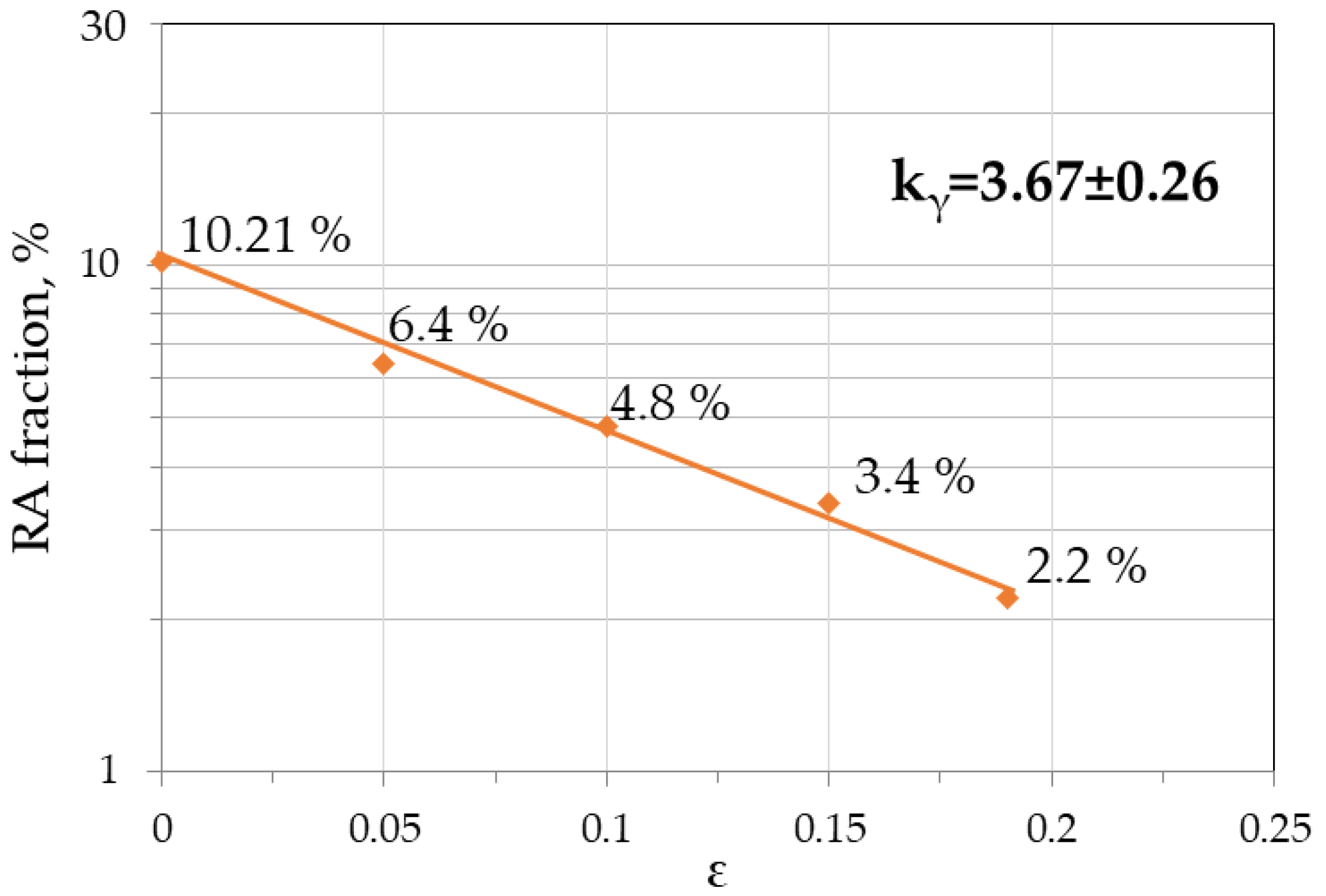
Retained austenite fraction at tensile strain levels
5%10%15%Fracture—19.5%
0.0640.0480.0340.022
Table 2. Mechanical properties of steel obtained in semi-industrial rolling process.
YS0,2,
[MPa]
UTS,
[MPa]
TEl,
[%]
UEl,
[%]
YS0,2/UTSUTS•UEl,
[MPa•%]
472 ± 18690 ± 2119.5 ± 2.315.6 ± 1.50.6810,764
Publisher’s Note: MDPI stays neutral with regard to jurisdictional claims in published maps and institutional affiliations.

