Review

Review of Adaptive Shock Control Systems

by
Sven Christian Künnecke
1,*,
Srinivas Vasista
1,
Johannes Riemenschneider
1,
Ralf Keimer
1 and
Markus Kintscher
2
1
Institute of Composite Structures and Adaptive Systems, German Aerospace Center (DLR), 38108 Brunswick, Germany
2
Program Aeronautics, German Aerospace Center (DLR), 38108 Brunswick, Germany
*
Author to whom correspondence should be addressed.
Appl. Sci. 2021, 11(2), 817; https://doi.org/10.3390/app11020817
Submission received: 18 December 2020 / Revised: 8 January 2021 / Accepted: 12 January 2021 / Published: 16 January 2021
(This article belongs to the Special Issue Smart Aircraft Morphing Technologies)

Abstract

:
Drag reduction plays a major role in future aircraft design in order to lower emissions in aviation. In transonic flight, the transonic shock induces wave drag and thus increases the overall aircraft drag and hence emissions. In the past decades, shock control has been investigated intensively from an aerodynamic point of view and has proven its efficacy in terms of reducing wave drag. Furthermore, a number of concepts for shock control bumps (SCBs) that can adapt their position and height have been introduced. The implementation of adaptive SCBs requires a trade-off between aerodynamic benefits, system complexity and overall robustness. The challenge is to find a system with low complexity which still generates sufficient aerodynamic improvement to attain an overall system benefit. The objectives of this paper are to summarize adaptive concepts for shock control, and to evaluate and compare them in terms of their advantages and challenges of their system integrity so as to offer a basis for robust comparisons. The investigated concepts include different actuation systems as conventional spoiler actuators, shape memory alloys (SMAs) or pressurized elements. Near-term applications are seen for spoiler actuator concepts while highest controllability is identified for concepts several with smaller actuators such as SMAs.

1. Introduction

The reduction of greenhouse gas emissions is one of the most prominent challenges facing all transportation sectors today and especially so in aviation. To accomplish global objectives, such as those outlined in Flightpath 2050 [1], NASA’s Environmentally Responsible Aviation (ERA) project [2], the German aviation strategy [3] and the European Green Deal [4], aircraft must be more efficient to reduce their emissions during operation. Aside from alternative fuels or weight reduction strategies, several other ideas and approaches to increase aircraft efficiency are under investigation including laminar flow wing technologies and turbulent skin friction reduction for reducing friction drag, and high aspect ratio wings for reducing lift-induced drag as summarized in [5]. Since transport aircraft usually travel at transonic speeds, wave drag generated by transonic shocks on the wing surfaces also provides a significant contribution to overall aircraft drag. Furthermore, the phenomenon of buffet can occur which can lead to structural vibrations and thus limit the flight envelop [6,7,8]. For a review of transonic shock buffet the reader is referred to Giannelis et al. [9]. Research into shock control for transonic airplanes over the last few decades has been motivated by the possibility to reduce wave drag, as well as recent investigations into delaying buffet onset. The goals of shock control are to implement a device which reduces the shock strength and consequently wave drag and/or to delay the buffet onset and thus to reduce emissions, extend the flight envelop and/or reduce flow induced vibrations. While the drag reduction potential of SCBs has been investigated over almost the past three decades [10,11,12,13,14,15,16,17,18,19,20,21,22,23,24,25], buffet control by SCBs has been investigated less extensively [6,7,8,9,26,27,28,29]. For detailed research on buffet control via SCBs the reader is referred to Mayer [6] and Mayer et al. [7].
In 1992, Ashill et al. [10] introduced the concept of SCBs as a promising method to reduce the strength of a transonic shock, since such a local contour change in the vicinity of the shock can reduce the strength of the shock and thus has the potential to reduce the overall drag of an aircraft and therefore the overall fuel consumption and emissions. For a detailed review of aerodynamic investigations of SCBs the reader is referred to Bruce and Colliss [25]. The current review paper here is complementary to [25] in that focus is placed on adaptive concepts.
Several substantial aerodynamic investigations into SCBs have been carried out among which the two European projects EUROSHOCK (1993–1995) [12] and EUROSHOCK II (1996–1999) [16] play a major role. In EUROSHOCK, passive shock control devices like perforated skins with cavities beneath them (porosities) have been investigated. Although these concepts show indeed a reduction in wave drag, they also lead to an increase in viscous drag and thus to an increase in total drag (on the investigated laminar wings) [12]. Therefore, in EUROSHOCK II adaptive systems have been analyzed like perforated strips and cavities with suction, ventilation or hybrid-control as well as physical contour bumps with and without suction. As with the results of EUROSHOCK, the results of EUROSHOCK II show a total drag increase for almost all variants of porosities. However, the physical contour bump was found to be very effective. In particular, an adaptive SCB which is variable in its height and in combination with a discrete suction upstream of the bump shows the highest potential for reducing both wave and total drag. Therefore, the recommendation for the use of adaptive SCBs to cover a wider flight envelope range is given. Another interesting finding of EUROSHOCK II regarding shock control is the positive effect of SCBs on the buffet boundary [16,30,31].
SCBs analyzed in EUROSHOCK II have a fixed location on the wing and thus are not variable in their positions. This means that these SCBs are optimized for one single design point and therefore fixed in their location and shape. Although such SCBs decrease drag at the corresponding design point, they can increase drag at off-design conditions. During the period of the EUROSHOCK projects, research focused on robust but fixed SCB designs that reduce drag over a wider range of flight conditions since adaptive concepts did not have the capability as adaptive systems show today. However, nowadays adaptive systems have reached a high technological readiness and the implementation in real aircraft has been demonstrated. This is why adaptive SCBs that can vary their height and position offer substantial potential, since morphing bumps can mitigate aerodynamic penalties at off-design conditions.
Adaptive SCBs are one type of morphing wing technologies [32,33,34,35,36,37,38,39,40,41] which also include, e.g., morphing leading edges (droop nose) [42,43,44,45,46,47,48], morphing trailing edges [30,49,50,51] or morphing winglets [50,52]. In addition to two-dimensional (2D) bumps, the potential of three-dimensional (3D) SCBs for reducing drag and/or delaying buffet onset has been investigated [6,7,22,26,27,53,54,55,56,57]. A comparison between 2D and 3D bumps is given by Deng and Qin [58]. However, most of the adaptive SCB concepts presented in this review do not focus on 2D or 3D shaped bumps in particular but often the concepts could be used for both applications.
These results of the EUROSHOCK projects have been a main driver for the investigation of SCBs for wave drag reduction in the past two decades. This review aims to provide an overview of several adaptive shock control concepts including approaches that mainly use the spoiler actuator, concepts that use several smaller actuated elements, passive skin deformation due to pressure differences in the vicinity of the shock, as well as using plasma for shock mitigation purposes.
The goals of an adaptive shock control concept are to not only mitigate wave drag as well as overall drag but also to lower overall fuel burn. This is why, for example, the weight of the integrated adaptive system must not be excessively heavy, since otherwise the positive effect of drag reduction is compensated by the additional fuel needed for the increased weight. In general, the challenge is multidisciplinary whereby any added weight and complexity need to be offset by a sufficiently large aerodynamic benefit in order to achieve a net top-level benefit.
This paper summarizes adaptive SCB concepts and compares them in terms of their advantages and challenges with respect to their structural and system integration. Focus is given to whether these systems are able to adapt the bump location and its height, and if so, how that is achieved. Although a brief review of their aerodynamic effectiveness is sometimes given, the advantages and challenges regarding their systemic realization and structural design are the main focus of this work. Section 2 provides a literature review of adaptive SCB concepts and Section 3 presents a discussion in which the advantages as well as the challenges of the respective concepts are outlined. Furthermore, a comparative table of the introduced concepts is also presented. Section 4 draws a conclusion in terms of the practical applicability of the concepts and an outlook for future investigations into SCB design is given in Section 5.

2. Literature Review of Adaptive Concepts for Shock Control

A typical wing of conventional transport aircraft consists of movable parts for flight control such as flaps, slats, ailerons and spoilers. While the slats are located on the leading edge (LE), the flaps (inboard) and ailerons (outboard) form the trailing edge (TE) of the wing. The spoilers are mounted upstream of the flaps and responsible, e.g., for the airbrake, lift dumping and enabling coordinated turns. Hence, they must bear comparable high loads during the landing phase.
In this section, the results of a literature study are summarized. There are several ways to approach the challenge of designing adaptive SCBs or similar systems for shock control. Since conventional transport aircraft generally use spoilers and flaps for flight control, and since the transonic shock is often located on the spoiler, several concepts focus upon this wing region. Advantages of using a morphing spoiler to form the SCB is that there is already an actuation system present and that there is a good chance of having enough installation space for additional components—in contrary, e.g., to the wing box where an implementation of additional parts would decrease the tank volume or the aileron region where the wing is rather thin.
As described above, SCBs are the most promising approach for wave drag reduction by weakening the transonic shock which is why most of the following concepts include the formation of a bump on the wing suction side. To get an understanding of this kind of shock control, the aerodynamic phenomenon is depicted in Figure 1.
Depending on the design and the shape of the SCB, the main shock is bifurcated by the bump into several isentropic compression waves for a smooth transition from airfoil to bump (Figure 1b) or into the so called lambda shock structure (λ-shock) with a front and a rear leg if the SCB is more wedge-shaped and has a kink on the transition from airfoil to bump (Figure 1c) which is highly beneficial in terms of wave drag reduction [14,15,22,23,25,59,60].
As Sommerer et al. [15] investigated, the bump shape plays only a minor role in terms of drag reduction and the SCB location and height are the two most important parameters. However, as also shown in Figure 1, the type of shock interference depends on the shape of the bump. According to Mayer [6], the smooth transition leads to isentropic compressions waves and might perform better whilst the kink anchor with a wedge-shaped bump is more robust towards flow condition changes [61]. However, the SCB height, position as well as the location of the crest are very important for an effective and robust bump design [27,55,59,60]. This is why an accurate control of the SCB should be enabled by an adaptive system. The following section reviews several SCB concepts with regard to such functionalities.

2.1. Preformed Spoiler Concepts

2.1.1. One-Actuator Concept

In 2016, Kirn et al. [62] and Machunze et al. [63] published this concept of a preformed spoiler geometry and in 2019 the corresponding patent by Hansen et al. [64] was released. The spoiler forms the bump in its preformed state and can be transformed to an almost plane form—which represents the clean cruise shape—by increasing the pulling force of the spoiler actuator, which is shown in Figure 2.
Since the flap serves as counter force, the contact point of the spoiler can slide on the flap when the actuator pulls the spoiler into its planar shape. Besides the preformed structure another structural element deserves attention. The authors invented a flexible solid body hinge which serves as an alternative to the conventional spoiler joint. Termed “flexible hinge”, this part consists of a flexure hinge made of carbon fiber reinforced polymer (CFRP) which replaces the conventional jointed hinge [62,63,65]. Since this technology is gapless and stepless, it prevents the airflow from undesired disturbances, as they could occur through a conventional spoiler joint. Moreover, another part of the spoiler is structurally modified and reduced in its stiffness. This so-called bump hinge or cut-out part of the spoiler is located between the two stiffer sections. It is needed for an accurate positioning of the bump crest. On the one hand, this bump hinge introduces enough flexibility of the spoiler during the bump formation and, on the other hand, it provides sufficient stiffness for the airbrake load case.
The forces during the airbrake are not only a challenge for the bump hinge section but especially for the flexible hinge. Since this spoiler region must be designed with a rather small skin thickness to enable a large deformation, it would not be able to bear the loads on its own. For this purpose, Hansen et al. [65] describe guiding kinematics which serve as supporting mechanism to bear the aerodynamic forces, so that the flexible hinge is only loaded with pure bending.
Kirn et al. [62] assume a bump height variation of 0.1 to 0.5% chord length and a variation of the shock location of 15 to 20% chord. While the height of the bump can be adjusted by a variation of actuator force, the bump crest position cannot be changed. Kirn et al. [62] instead utilize the variable camber (VC) functionality to adjust flap position by several degrees to ensure that the shock coincides with the fixed bump position which is described by Werner [66] in more detail.
An additional version of this concept is realized by the implementation of a secondary actuator which reinforces the bump hinge section of the spoiler. This is mentioned in the patent of Hansen et al. [64]. With this additional actuator the shape of the bump can be controlled more accurately and, moreover, the spoiler can form a plane shape in the high-lift configuration and the airbrake case due to the increased stiffness. Furthermore, a concept of using an accurate mechanism instead of a second actuator is also conceivable [64]. In the following section, the approach by using a secondary actuator is described.

2.1.2. Two-Actuator Concept

Based on the work of Kirn et al. [62] and Machunze et al. [63], Kintscher and Monner [67] presented in 2017 a concept of an adaptive spoiler that uses a secondary actuator in addition to the main spoiler actuator. Aside from the two actuators, this system consists of two structural reinforced skin parts and guiding rails for the main spoiler actuator, which is shown in Figure 3. Furthermore, the spoiler TE section is preformed and also the flexible hinge is used instead of a conventional spoiler hinge, which mandates the use of guiding rails. Moreover, the structure between the two reinforcements is modified and enabled to be more flexible. This leads to a maximum forward bump position located at the thin spoiler skin between the two reinforcements while the maximum backward bump position is created just behind the reinforcement near the TE.
Contrary to the concept of the former section, the spoiler of Kintscher and Monner can vary its bump position within a limited range of 7.5% chord. However, the position variation is only limited to the location of the reinforcements, which means that if enough installation space is given larger position variations could also be possible. Furthermore, maximum bump heights of 0.76% chord for the maximum forward bump crest position and 0.62% chord for the maximum backward position have been reached.
Kintscher and Monner [67] investigate four primary load cases: (i) The cruise flight with a pressure load of 4000 Pa and ±10% load variation, (ii) the airbrake case with 5000 Pa as well as (iii) the maximum forward and (iv) maximum backward SCB positions. Moreover, the primary installation actuator angle is varied in a range of 10°, 20° and 30°, as shown in Figure 4, to lower the actuator forces.
The increase of the primary actuator angle from 10° to 30° decreases the primary actuator force by approximately 50%. Also, the necessary forces in the other load cases decrease. The forces of the secondary actuator were not influenced distinctly by this angle variation of the primary actuator. The design driving load case for the primary actuator is the airbrake since a maximum force of 40 kN is reached. The secondary actuator needs 20 kN at airbrake conditions. With an opposite direction of force, the other three load cases lead to forces of maximum 25–27 kN in both actuators. Thus, all loads stay within the given limit of about 40 kN which represents the spoiler actuator force of a typical short-medium range aircraft. Moreover, the deviations of the spoiler shape to the reference shape should stay below the limit of ±0.5 mm, which is the case for the cruise pressure load variations of ±10% simulated in this design process [67].
From a structural point of view, again the airbrake load case is design driving. The flexible hinge region has been reduced to 1.5 mm skin thickness which results in a maximum principal strain of 0.8%. Two general possibilities to reduce the strain in this hinge region are to decrease the skin thickness or extend the length of the flexible hinge. However, in this design the thickness of 1.5 mm is already approaching practical minimum limits [67].

2.2. Shock Control Concepts Using Multiple Actuators or Adaptive Elements

In Section 2.2.1, Section 2.2.2 and Section 2.2.4, actuators are introduced that use shape memory alloys (SMAs) for actuation. These metal alloys can be loaded and deformed, but are able to recover their initial shape by thermal energy. This heat can be applied to SMAs by an electrical current which implies that cables are needed for suppling this actuation energy. In general, SMAs have a large work output per actuator mass, which makes them promising for applications with limited installation space.

2.2.1. Fish-Mouth Actuator

In 2000, Pritschow et al. [68] proposed several possibilities to form an adaptive bump with SMAs. One of these concepts was introduced under the name fish-mouth actuator by Campanile et al. [69] also in 2000 and further described by Wadehn et al. [70] in 2002, Campanile and Keimer [71] in 2003 and Campanile et al. [72] in 2004. The setup of one of these SMA actuators is demonstrated in Figure 5.
The fish-mouth actuator consists of a composite spring, a carbon stiffener on top and a bundle of SMA wires in between, which are made from nickel-titanium (NiTi). These SMA wires are pre-strained and can be activated by heat (introduced by an electric current). Two copper clamps at both sides bind the spring and wires. Through their activation, the wires are contracted in longitudinal wire direction and deform the surrounding spring. The whole actuator is mounted on a metal plate to enable a deformation only in the upwards direction and consequently against an above mounted flexible skin to form the SCB. The actuators are placed next to one another in chordwise direction which is depicted in Figure 6.
The composite spring fulfills several tasks including the conversion of the longitudinal wire contraction into a transversal movement as well as an amplification of this motion. Furthermore, the motion into the original actuator shape (before activation) is driven by the tension in the composite spring. Consequently, the SMA wires are only responsible for the formation of the bump while the spring realizes the movement back to the flat shape of the flexible spoiler skin.

Actuator Geometry and Structural Design

The following description is based on Campanile et al. [72] (2004). Over 400 fish-mouth actuators were manufactured for a wind tunnel model of which 84 have been implemented into the experimental model. With a chord length of 400 mm and a desired maximum bump height of 0.5% chord, the desired maximum stroke of one actuator is 2 mm. The stiff part of the actuator has a length of 30 mm, and with a total width of the composite spring of 50 mm this leaves 10 mm on both sides to form variable parts of the composite spring. The actuator height amounts to 8 mm (including 1 mm thickness of the laminate on top of the actuator). This geometric setup is depicted in Figure 7.
The NiTi-SMA wires feature a diameter of 0.392 mm and an austenitic start temperature of 88 °C. With this configuration a force of 200 N is used in the final design configuration as well as a transverse stiffness of 70 N/mm. The maximum actuator force (blocking force) amounts to 240 N [72].

2.2.2. Tube Spring Actuator

The Tube Spring actuator concept was introduced by Bein et al. [73,74] (1998, 2000) and investigated also by Monner et al. [49] (2000). It focusses also on an adaptive spoiler in which the actuators are mounted on a load carrying structure and covered by a flexible spoiler skin, against which the actuators push when activated. Similar to the fish-mouth actuators, several of these so-called Tube Springs are implemented in chordwise direction into the spoiler (compare Figure 6). The single actuator is shaped like a lying eight and has a stringer in the middle which is depicted in Figure 8.
The actuator is made from CFRP and when activated it pushes the stringer upwards against the flexible spoiler skin which then forms a SCB. The authors mention two embodiments of this actuator. In a first variant, pressure is used for activation and therefore the concept consists of an additional inner rubber hose. Consequently, the wing must be equipped with a system for the pressure fluid inside the wing consisting out of values, tubes and pumps as well as a suitable sealing of the pressure system. The second concept variant uses SMAs to realize a deformation, which are mounted on the upper half of the Tube Spring. An activation of the SMAs leads to a deformation of the whole spring, similar to the activation via pressure [49,74].

2.2.3. Pressurized Chambers
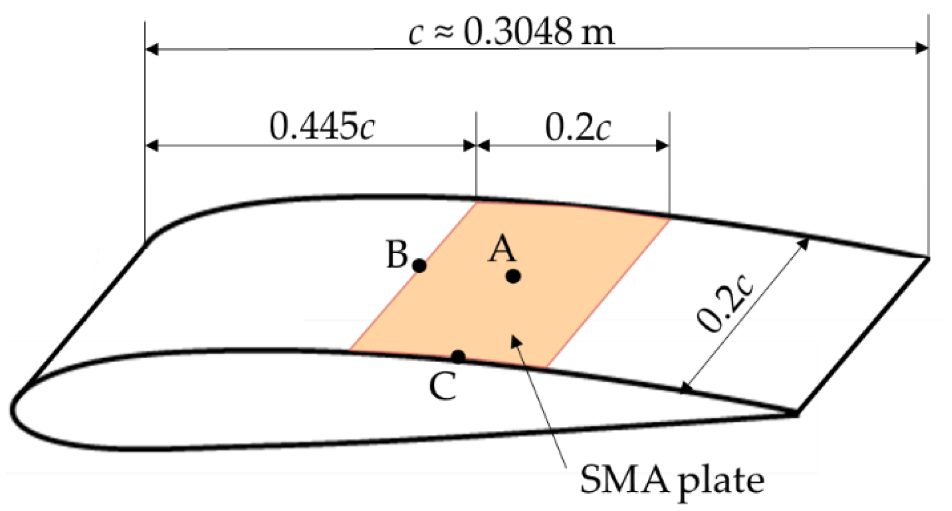
In 2015, Kintscher et al. [75] developed a SCB concept with several chambers on which pressure can be applied, to expand them. This concept has been refined by Alves de Sousa et al. [76] (2020). The expanding chambers push against a flexible spoiler skin, whereby the bump is formed, which is shown in Figure 9.
As with many others, this concept focusses on the spoiler but since the spoiler mechanisms and functions are not touched, a full redesign of the spoiler is not necessary, which is comparable to the Tube Spring and fish-mouth actuators. The morphing spoiler consists of three layers of which the bottom layer depicts the supporting structure while the top layer is represented by a flexible skin material. The layer in between comprises the pressure chambers. For these chambers flexible walls are implemented to enable a deformation. Since the chambers are independent of each other the pressure can be adjusted differently in each chamber.
The chambers and the skin are fixed on the edges in chordwise direction. This leads to an expansion of the chambers towards the wing’s suction side. Hence, the flexible skin is deformed. A means of sealing has to also be realized at the edges in spanwise direction. For the spoiler closings in spanwise direction, Kintscher et al. [75] describe three different types: open ends, fixed ends and closed ends with a fiber glass plate (which has a thickness of 1 mm). With regard to the deformations, the fixed and closed ends show an almost equal behavior. Compared to the open ends, the fixed and closed ends lead to a much stiffer design, distinctly lower deformation than wanted and a different peak location. Furthermore, waviness close to the spoiler trailing edge occurs. Based on these phenomena as well as positive effects with open ends like an uniform bump shape and a lower actuation pressure, Kintscher et al. [75] describe a spoiler with open ends that offers the best shape behavior, although the question of how to enclose the fluid remains.
Since the number of chambers is directly linked to the weight increase and system complexity, Kintscher et al. [75] analyzed the effect of two and three chambers in chordwise direction. The results show that the three-chamber design can lead to a reduction of the needed chamber pressure. However, with the third chamber an additional chamber wall has to be implemented which adds flexural rigidity to the system. This is why for every spoiler and wing configuration it should be analyzed how many chambers are optimal for the respective design.
The 2D two-chamber design of the flexible skin is described by Alves de Sousa et al. [76] as a 5 mm thick glass fiber reinforced polymer (GFRP). The S-shaped stringer respectively wall between both chambers is also made out of GFRP. The supporting structure and the active layer consist of CFRP and unidirectional GFRP. With a chordwise spoiler length of 1 m, the maximum achievable bump height is 8.16 mm and the maximum principal strain amounts to 0.45%. Moreover, a focus was placed on the spoiler tips in spanwise direction. At both ends, the tips amount to 10% of the spanwise length of the spoiler. Nevertheless, the differences of the spoiler tip deformations only differ for about 1 to 5%, depending on the particular design.

2.2.4. SMA Plate

Hao et al. [77] (2018) describe the possibility to use an SMA plate, integrated into the wing suction side, to generate a 3D bump. Since the authors assume the bump’s expansion in chordwise direction to be 20% of the chord, the expansion in spanwise direction is also set to 20% chord, which makes the plate quadratic. This is depicted in Figure 10.
In the initial stage the SMA plate has the shape of the original airfoil and is pre-strained, which means that the initial strains in chordwise and spanwise directions are negative. The initial temperature of the plate is −5 °C at which the SMA is fully martensitic. When the temperature is increased the SMA transforms into the austenitic phase. At the three considered points on the plate this transformation starts at about −1.8 °C and is fully completed for the point A in the middle of the plate at 6.2 °C. On the boundaries, however, a larger temperature increase is needed, since these are the areas of a high stress concentration. Even at the highest considered temperature of 15 °C these regions (point B and C) are not fully austenitic. However, for the formation of the bump it is sufficient that only the middle of the plate is transformed fully. Under the circumstances considered in [77], the SMA plate reaches a maximum bump height of 2.4 mm. With a given chord length of 0.3048 m this corresponds with a relative height of 0.79% chord. Nevertheless, higher bump crests can be reached within the same temperature range if the maximum transformation strains are changed. For higher transformation strains a value of even 3.25 mm (1.07% chord) could be reached [77].
A similar approach is described by Zhang et al. [78] who apply an SMA plate made of NiTi with the dimensions 2 mm × 44 mm × 76.5 mm in a wind tunnel to create a bump. However, since the application described in [78] focusses on supersonic inlets and the tests are carried out at Mach 2.0 to 3.8, the aim differs somewhat from the transonic shock alleviation discussed in this review. Nevertheless, the general idea of such an SMA plate is applicable for transonic shocks as well.

2.3. Using Pressure Differences in the Shock Region

The underlying idea of using perforated strips and cavities in the EUROSHOCK projects [12,16], as introduced in Section 1, is based on different pressure levels which are present in the vicinity of the transonic shock. These pressure differences can lead to a re-circulation of the air flow through the cavity and perforated skin and thus affect the shock [12,16,79,80]. Moreover, these pressure differences can also be used to deform a flexible plate which is described in the following section.

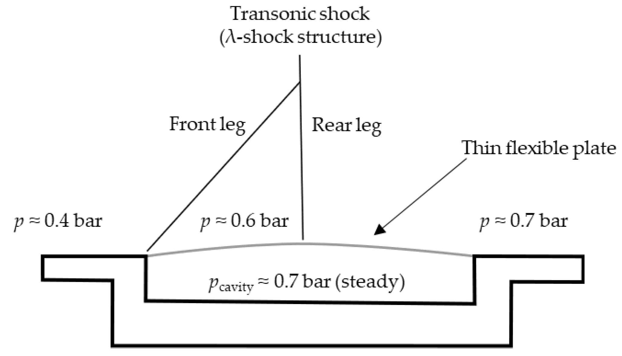
2.3.1. Thin Flexible Plate

Jinks et al. [81] (2015) describe a passive concept as well as an additional actuated approach. For both concepts the authors performed simulations with coupled fluid–structure interaction (FSI) as well as wind tunnel measurements. Similar simulations using FSI have been performed by Gramola et al. [82,83] and Shinde et al. [84,85].
The general idea of the passive concept is based on a flexible plate on an airfoil suction side that is deformed only by the depression due to the airflow aerodynamics in the transonic shock vicinity. Similar to the porosity that has been debated in Section 1, this concept applies the pressure differences in the shock regime. As depicted in Figure 11, the pressure levels in the supersonic region as well as in the direct shock vicinity are lower than the pressure downstream of the shock. By implementing a cavity beneath a flexible skin and by appropriately adjusting the cavity pressure, the pressure difference can cause a deformation of the flexible material. This deformation leads to a bump formation which is affecting the transonic shock similar to an adaptive SCB, as can be seen in Figure 11.
For the wind tunnel model, Jinks et al. [81] use a 0.4 mm thin aluminum plate (Al 7075 T6) that reaches from 40 to 60% chord. Since the shock is located at about 50% chord it is almost in the middle of the flexible airfoil surface. The airfoil chord length is given as 1 m. The investigated cavity pressures range from 0.3 to 1.0 bar and for the experiments in a Mach 1.4 wind tunnel a value of about 0.7 bar has been chosen.
Since the cavity pressure is the only control variable and the bump position cannot be controlled with such a passive approach, Jinks et al. [81] suggest an additional actuated concept which was originally proposed by Ashill et al. [10] in 1992. This SCB concept uses an actuated flexible plate which is described in the following section.

2.3.2. Actuated Thin Flexible Plate

An advancement of the flexible plate approach from Section 2.3.1 is an actuated solution in which Jinks et al. [81] use a Haydon-Kerk 25443 actuator with a maximum displacement of 18 mm. This actuator is located in the middle of the flexible plate. This actuator can be used to extend the airfoil surface by pushing against it and the actuator can, conversely, retract and thus hold the surface down, which is depicted in Figure 12.
In the retracted case (Figure 12a) the bump crest position is further upstream while with extending the actuator (Figure 12b) the bump moves towards the trailing edge. It could be detected that the cavity pressure has a distinctively smaller effect on the bump geometry compared to the non-actuated flexible plate [81].
While in [81] (2015) the maximum stress in the single actuation point is approximately 69% of the yield stress, Jinks et al. [86] (2016) could reduce this value to a reported 58% yield stress. Hence, in both approaches the stresses are far below 90% yield stress (safety factor: 10%) which the authors chose as limit.
Whilst a smaller skin thickness will allow for lower actuation forces for the same deflection, questions relating to the robustness of such low thicknesses (e.g., impact damage and corresponding maintenance and repair time and costs) still remain.

2.3.3. Thin Flexible Plate with Two Actuation Points

In 2018, Jinks et al. [87] described another concept consisting of two actuators and a thin flexible skin. This design was already proposed by Ashill et al. [10] in 1992 and is shown in Figure 13.
Although for this concept the thin flexible plate is not explicitly described as a 0.4 mm thin plate, it is to be assumed that a similar plate as in [81,86] (Section 2.3.1 and Section 2.3.2) is used in [87], since the authors mention that the aerodynamic pressure also plays an important role by forming the SCB shape. However, the authors do not describe the importance of the cavity pressure for this concept, which could mean that it is comparably independent of this variable.
As mentioned before, Jinks et al. [81,86] could keep the maximum von Mieses stresses below the limit of 90% yield stress. This is also true for the two-actuator solution in both actuation points [87].
Rhodes [35] (2012) analyzed the impact of using one, two or more actuation points to form a SCB. The result is that only minor benefits occur if more than two actuation points are considered with respect to the bump’s shape accuracy. This is why, in the scope of this review, the concepts by Jinks et al. [87] (2018) and Ashill et al. (1992) seem to be a promising approach and trade-off between rather low complexity but still sufficient morphing functionality. However, it remains unanswered if also the position variation of the bump can sufficiently be implemented by using only two actuators.

2.4. Compliant Structures with One Actuator

In 2006, a patent of Kota and Hetrick [88] was released which contains the capability of morphing compliant and resilient structures to influence the fluid flow characteristics. Among these claims is also the embodiment of a surface bump for shock control as it is depicted in Figure 14. The compliant structures are deformed by an actuator, move upwards and push against a flexible skin, whereby the bump is created.
As can be seen in Figure 14, only one actuator it used, however, this actuator does not have to be the spoiler actuator and the concept could also include several actuators. In [88] camber control used in collaboration with the bump is also mentioned. The general idea of applying compliant structures for adaptive shock control concepts offers a wide range of opportunities. Such structures are also conceivable in combination with one of the other concepts described in this review. The load transfer through the compliant mechanisms can lead to a realization of an adaptive SCB in wing areas with comparably less installation space.

2.5. Plasma Heating Elements

The possibility to influence the air flow and the boundary layer as well as reducing the drag (e.g., of a blunt body) by inducing a plasma has already been investigated widely [89,90,91,92,93,94,95]. With regards to transonic shock reduction, Chang et al. [96,97] (2012, 2019) describe the possibility to influence the air flow on an aircraft wing by creating a plasma. Such concepts consist basically of a plasma generator, a power source, a sensor and a controller. As shown in Figure 15, the plasma generator could, e.g., be conducted with two electrodes (a) or one single electrode (b), whereby these electrodes could also be recessed into the surface.
The electric current in the plasma heats up the surrounding air flow which leads to changes in temperature and pressure. This can increase the local speed of sound limit which reduces the Mach number and consequently the strength of the shock. Under certain circumstances, the formation of the shock could be prevented entirely [97].
According to Lin et al. [98] (2012), drag reductions of about 13% have been simulated, using a thermal source term model for a RAE2822 airfoil at Mach 0.81. The simulated approach seems to be similar to the patents of Chang et al. [96,97], however, no information is given in [98] if these drag reductions refer to the total airfoil drag or only to wave drag. Furthermore, a necessary temperature of 3000 K is denoted in [98].

3. Discussion

The above introduced adaptive systems and concepts to alleviate the strength of a transonic shock on an aircraft wing use different approaches to form a SCB or to influence the air flow near the shock. In the following, the above described concepts are grouped and analyzed in terms of their advantages as well as their challenges which are to be faced with the respective systems. At the end of this section, this discussion is summarized in Table 1.

3.1. Concept 1—Perforated Skin/Porosity (Passive Approach)

This concept comprises the wave drag reduction potential by a re-circulation through a porous material and an underlying cavity, which was mentioned in the introduction.

3.1.1. Advantages

The passive design and consequent low complexity are key advantageous features of this approach. Furthermore, this concept requires very little installation space, thus, it could be applied on almost any region of the wing.

3.1.2. Challenges

It has been reported that whilst wave drag was reduced by the perforated skin, the viscous component of drag increased which led to an overall drag increase [12]. The challenge to design a porous surface that decreases the overall drag hereby exists. Moreover, any porous surface concept in aeronautical applications (e.g., hybrid laminar flow, suction, blowing etc. [31,99,100,101]) is susceptible to blockages from daily operations, and in this case may inhibit the re-circulation of the airflow. Consequently, an adequate solution needs to be found to purify the porosity from particles or prevent the contamination at all.

3.2. Concept 2—Preformed Spoiler

This concept is based on Section 2.1.1 and Section 2.1.2 in which variants of an adaptive spoiler are described that use mainly the spoiler actuator to pull the preformed spoiler shape, which represents the bump shape, into clean configuration.

3.2.1. Advantages

In relation to systems with several smaller actuators, this concept stays comparably simple. If only the spoiler actuator is used for morphing, as in Section 2.1.1 [62,63,64,65], only the spoiler structure needs to be modified into a morphing device and so any total weight increase is expected to remain comparatively low. The implementation of the secondary actuator adds the functionality of the SCB position variation to the system (Section 2.1.2), which is together with the SCB height variation extremely important for SCB control. Furthermore, both concept variants use components with high technological readiness. If the concept is applied as in Section 2.1.1 [62,63,64,65] (one actuator) or Section 2.1.2 [67] (two actuators), the flexible hinge technology offers additional opportunities for future wing designs, irrespective of the usage of SCBs on the spoiler.

3.2.2. Challenges

The simplest embodiment with only one degree of freedom does not have the ability to independently adapt the SCB height and position. This is why VC is needed to hold the shock on a desired location. It should be investigated if VC can be applied in a sufficiently wide range of flight conditions.
Moreover, if the bump shape is to be controlled more accurately and the spoiler shape should stay rather planar in the high-lift configuration as well as in the airbrake case, a second actuator or mechanism is needed which increases weight and complexity. Also, the installation space with a second actuator may limit the implementation of this concept to inboard regions of the wing.
Furthermore, the flexible hinge must be designed very carefully in terms of fatigue and ultimate loads. The guiding devices can bear the loads and enable the usage of the flexible hinge, however, these guiding devices increase weight and additional installation space. Although this hinge solution is not mandatory for the general bump concept, a similar structural modification applies to the cut-out section (bump hinge). If this bump hinge cannot handle the loads on its own, the secondary actuator or mechanism would have to be included to add stiffness and stability to this spoiler part.
In addition, the formation of 2D bumps is easiest to realize with spoiler actuator concepts. The formation of 3D SCBs is, however, rather challenging to implement since there are only a few spoiler actuators and the bump can only be created at the position of the actuator.

3.3. Concept 3—SMA Wire Bundle Actuators

This concept comprises ideas of using several smaller actuators that consist of SMA wire bundles and that are installed behind each other in chordwise direction. Above introduced literature concepts are the fish-mouth (Section 2.2.1) and the Tube Spring actuators (Section 2.2.2).

3.3.1. Advantages

SMA actuators can be designed to be highly compact, thus, they can be used in wing regions with limited installation space. The SMA actuation requires only an electrical power supply to introduce heat to the SMA wires which is expected to mitigate the overall system weight increase with respect to other actuation technologies such as hydraulic fluid systems. Furthermore, due to the fact that several actuators are placed in chordwise direction, the bump is not only variable in its height (depending on the amount of supplied heat) but also in its position as well as shape. Also, the formation of both 2D and 3D bumps is conceivable.

3.3.2. Challenges

Such systems are rather difficult to control since a large number of actuators must be powered. The single actuators must be manufactured with great accuracy to ensure the same properties for all of them. However, substantial progress has been made in the last decades by manufacturing SMA actuators [102,103]. Moreover, SMA actuators need a continuous heat supply during actuation if no locking mechanism is installed or another solution is found to reduce the energy amount of such systems.

3.4. Concept 4—SMA Plate

This concept is based on the SMA plate introduced in Section 2.2.4 that is clamped on all four sides and which forms a bump by buckling. The resulting SCB is in 3D.

3.4.1. Advantages

The advantages of reduced installation space, low weight increase and variable SCB height, as mentioned for the SMA actuators of concept 3, are also true for a plate made out of SMAs.

3.4.2. Challenges

Aside from the previously-mentioned points for SMA actuators in general, the following additional challenges for an SMA plate are foreseen. Given the difficulty in adjusting bump crest position, a careful design method and accompanying aerodynamic investigations need to be established to ensure drag reduction in a wide range of flight conditions. Furthermore, a strategy for limiting the required energy for the SMA plate is required given that the plate has a large surface and will be cooled by the surrounding air flow. Hence, to reduce heat losses, the plate should be adequately thermally isolated from exposed airflow.
Although the performance of 2D and 3D bumps at design point in terms of drag reduction is comparable [58], the buffet behavior is effected less strongly by 3D bumps [27]. Furthermore, it might be challenging to match the 3D aerodynamic target shape especially at the bump edges with sufficient accuracy. Alternatively, strategies for modifying the plate design to allow for 2D bumps without excessive complexity need to be determined for the SMA plate.

3.5. Concept 5—Pressure-Actuated Concepts

This section focuses on the pressurized chambers (Section 2.2.3) and the Tube Spring actuators (Section 2.2.2) concepts. Both can be actuated by a pressure fluid and consist of at least two actuated elements or chambers, and both are described for a morphing spoiler in which the actuated elements are implemented. Both concepts can be actuated by pressure and share some similarities. However, they also differ in certain aspects.

3.5.1. Advantages

Both approaches can adapt the height, position and shape of the SCB. The chamber-approach can be designed with three or two chambers, which leads to less complexity compared to the Tube Spring concept, and still provides sufficient controllability. However, although concepts such as the Tube Spring with several smaller actuators are more complex, the shape control can be greater due to the larger number of actuated elements. According to [76] however, the chamber concept seems to be a feasible trade-off between accurate shape control and complexity. Moreover, even if these approaches focus on the spoiler, an application elsewhere on the wing might be possible, provided that sufficient installation space is given, and in addition to that, the formation of both 2D and 3D bumps are viable.

3.5.2. Challenges

Pressure systems in general feature more complex setups with respect to purely electrically driven actuation systems since components such as valves, pumps, tubes and accumulators are needed. The sealing of fluidic pressure is also a key issue and adequate solutions to ensure design simplicity and to prevent loss of control are needed. Furthermore, especially if compressible air is used as the working medium, the development of an adequate control system is also needed. The means of extraction and/or supply of fluidic medium also requires careful design to ensure that the overall system does not exceed energy and weight budgets.

3.6. Concept 6—Thin Flexible Plate Deformation by Airflow Pressure Differences

This concept comprises the ideas of using the natural pressure differences in the vicinity of the transonic shock to deform a flexible plate which form a SCB. The literature concepts have been introduced in Section 2.3.1, Section 2.3.2 and Section 2.3.3.

3.6.1. Advantages

The passive nature of the simple non-actuated flexible plate offers an advantage. However, the cavity pressure has to be controlled, which requires a high degree of accuracy. Furthermore, since this concept works without actuation it can also forego detecting or measuring the shock position. In addition, the needed installation space (without an actuator) is rather small, which makes the concept applicable to many locations and regions on the aircraft wing.
The actuated solutions show a higher robustness against flow condition changes and less sensitivity regarding the cavity pressure. The overall idea of using only one or two actuators is promising, driven largely by its simplicity. Furthermore, since the results of Rhodes [35] show that using more than two actuation points does not increase the accuracy of the bump shape significantly, additional complexity is also likely avoided. From these studies, it was clearly shown that the implementation of a second actuator increases the controllability of the concept distinctly and sufficiently so to prevent additional actuators.

3.6.2. Challenges

With exception of the cavity pressure, the simplest non-actuated approach cannot be controlled and thus has no possibility to change the bump shape actively. The challenge hereby is, given all the sensitivities to external forces and conditions, how to implement this passive concept whilst ensuring enough stability and robustness to alleviate shocks when required and yet not cause undesirable effects. Furthermore, a robust design of the SCB without control must be found that leads to drag reductions over a wide range of flight conditions.
Although the solution with one actuation point introduced shape and position control, this control is still rather limited. Moreover, there is the challenge that the flexible plate might also be deformed under off-design conditions due to aerodynamic loads, which leads to the question how this influences flight efficiency and safety. Furthermore, the bump shapes are very sensitive in terms of cavity pressure, especially in the non-actuated case. This is why leakages must be avoided, which requires an accurate manufacturing and a well-designed sealing.
An additional challenge might be the low robustness of a rather thin flexible plate against mechanical influences, e.g., impact and damage by hail. However, if two actuation points are implemented the system seems to work also with a thicker plate which is not deformed by pressure differences. This could make the skin or plate more robust against mechanical damages and off-design conditions.

3.7. Concept 7—Compliant Structures

The approach of using compliant structures is introduced in Section 2.4. The remarks made here can also be used for compliant structures in general, and not just for the configuration as described in Section 2.4.

3.7.1. Advantages

Compliant structures offer advantages in terms of reduced wear, backlash and friction with respect to structures with conventional joints. Appropriate load tailoring can be achieved by synthesizing the design appropriately, including determining the best positions for the solid-state joints, tuning thicknesses, orienting composite plies appropriately (if used) and determining best topologies or layouts. Additionally, if designed appropriately, these compliant structures can offer advantages in terms of reduced maintenance and repair, provided the structures undergo strains sufficiently smaller than dynamic fatigue limits and are safeguarded against undesirable events (e.g., impact and lightning strike).

3.7.2. Challenges

A careful multidisciplinary design framework is needed to synthesize the compliant structure whilst ensuring that the system is adequately aerodynamically robust given the lack of independent control of both bump height and position. Such a design framework is also needed in the case of shock position control via VC. Overall weight mitigation also needs to be ensured given that larger actuators may be required in order to now work against structural stiffness and not only the external loads. An effective manufacturing and assembly strategy is also required for the selected materials given that compliant structure geometries tend to be complex. Joining techniques need to ensure that loads are properly transferred through the structure whilst preventing sharp stiffness gradients which may cause hard points and thus stress concentrations or irregularities in outer profile shapes which will detrimentally affect aerodynamic performance.

3.8. Concept 8—Shock Mitigation with Plasma

3.8.1. Advantages

Advantages include the small weight increase as well as the ability to implement in small installation spaces. Moreover, the concept is able to control the flow within an extremely short time frame [36]. In addition, since no mechanical moving parts are used the system should be mechanically more robust and feature reduced wear, in contrary to mechanical morphing systems.

3.8.2. Challenges

Methods for reducing the required overall energy are needed, given that a continuous high energy supply is needed for producing plasma. This reduction would need to be substantial enough to lead to an overall reduction in aircraft fuel burn. Given that this technology is in fundamental stages of research, overcoming this challenge would require an extended time. An additional challenge is the need to develop systems to shield fuel against electrical currents and charges from the plasma system.

3.9. Comparative Table of SCB Concepts

To summarize the advantages as well as the challenges of the introduced adaptive SCB concepts, Table 1 gives an overview of these systems and outlines the findings.

4. Conclusions

The adaptive SCB concepts reviewed in this work use various actuator technologies and approaches to morph a flexible skin into bump shape. The highest degree of controllability is given for concepts which use several smaller actuators (concepts 3 and 5, Table 1), although, for those concepts the complexity is often comparably high. Concepts which use a preformed spoiler shape in combination with the spoiler actuator (concept 2) use proven technologies and their complexity is comparably low. The preformed spoiler shape has been identified as a technology of great simplicity and utility. This is why the spoiler actuator concepts are found to be more advantageous if the shock is located on the spoiler and if simplicity is the main driver. Nevertheless, also the thin flexible plate which is deformed by only two actuators (concept 6 with two actuation points) seems to have accurate controllability and if it is designed with sufficient large skin thickness the robustness could be sufficiently high for an implementation in a real aircraft. Furthermore, it is simultaneously rather simple, which is why it is also found to be an appropriate concept. However, concept 6 (with two actuators) should be analyzed in due consideration with the bump’s position variation, since it stays unanswered if this concept can fulfil both a large position variation as well as an accurate bump shape control of the SCB. This is also true for the pressure chamber approach (one variant of concept 5) if only two chambers are used and should be analyzed, before choosing this concept.
The concepts that use several smaller actuators (fish-mouth and Tube Spring, concepts 3) or pressurized elements (concept 5) have the major advantage of ensuring the highest amount of SCB control (height, position and shape). The challenges are seen in the complex control of these actuators as well as in the manufacturing. Although SMAs are a promising actuator type for future aircraft wings, the energy demand has to be considered. A locking device or mechanism might be a solution to reduce the energy amount for the bump formation. The challenges for pressure actuated systems lie, on the one hand, in sealing the system and, on the other hand, in the weight increase by the pressure system. Nonetheless, the pressurized chambers offer reduced system complexity than the Tube Spring actuators, if they are driven by pressure. Moreover, SMA actuators provide large deformation energy also for small installation space. Especially for the outer wing regions their small size, and the fact that they depend only on electricity, makes them very interesting. Therefore, the SMA technology is found to be promising and it might work out well in combination with a thin flexible plate with, e.g., two actuators (concept 6). Although the compliant structures (concept 7) enable only a one-degree-of-freedom bump variation if designed as described in Section 2.4, the general idea of using compliant structures or mechanisms could provide an elegant solution for future SCB designs in terms of reduced part complexity in comparison with kinematic systems.
Despite the advantages due to their simplicity, the thin flexible plate approaches (concept 6) without or with only one single actuator do not seem to be rather robust against mechanical influences and the control is limited. The SMA plate (concept 4) needs a lot of heat and energy supply and must be very well insulated or the energy amount needs to be reduced differently. Finally, the plasma heating elements (concept 8) in its current stage require a lot of energy and its technology readiness is low for shock control.
In summary, several approaches already exist with a wide range of actuation concepts to form adaptive SCBs on aircraft wings. The focus lies often on an adaptive spoiler design, but also the installation in the outboard wing regions is possible with some approaches. Often an increased controllability goes hand in hand with increased complexity. Thus, the choice of concept is mostly a trade-off of how complex and heavy the system may become and how much drag can be reduced and, in the end, how much fuel can be saved. Concepts that use the spoiler actuator as well as concepts which manage accurate bump shapes with only a few actuators and additional components are found to be most promising.

5. Outlook

Future investigations of adaptive SCBs should look into drag reduction and overall system weight increase at the same time. Only with such an analysis can a conclusion be drawn as to how large the overall reductions in fuel consumption and emissions really are. However, since environmental aspects and goals are one of the main drivers for adaptive SCBs, the ecological design of such morphing systems and, e.g., the recycling should also be considered, which were not analyzed in this review. Furthermore, optimizers which use coupled FSI simulations for morphing systems offer a great potential for a fast and detailed design and should be considered more often for adaptive SCBs. To attempt an outlook, in the next five to ten years morphing components like adaptive spoiler SCBs could increase in their technological readiness. They can play an important role in reaching global emission targets and making aviation more efficient and environmentally friendly.
In the project Move-IntegR (FKZ: 20W1729C), position and height variable SCBs are to be designed for a wing with hybrid laminar flow control (HLFC). Various concepts to form SCBs on the spoiler will be considered and applied to performance and buffet-onset optimized designs, with and without VC.

Author Contributions

S.C.K. has executed the literature research and was responsible for writing this review. S.V. and J.R. supervised, reviewed and edited the work. R.K. reviewed the parts of the Tube Spring and fish-mouth actuators. M.K. worked in the former LuFo project LDAinOp and participated in developing the one- and two-actuator as well as pressurized chamber concepts and reviewed the respective sections of this work. All authors have read and agreed to the published version of the manuscript.

Funding

This research was funded in scope of the 5th Federal Aeronautical Research Program (LuFo) V-3 by the German Federal Ministry of Economic Affairs and Energy (BMWi) and is part of the project Move-IntegR (FKZ: 20W1729C).

Institutional Review Board Statement

Not applicable.

Informed Consent Statement

Not applicable.

Data Availability Statement

Data are stored on DLR institute servers and all papers and sources used for this review are inserted above.

Acknowledgments

Special thanks go to colleagues of the project partners in Move-IntegR from Airbus, the university of Stuttgart and DLR for the ongoing collaboration.

Conflicts of Interest

The authors declare no conflict of interest.

Abbreviations

The following abbreviations are used in this manuscript:
2DTwo-dimensional
3DThree-dimensional
BMWiFederal Ministry of Economic Affairs and Energy (of Germany)
CFRPCarbon fiber reinforced polymer
ERAEnvironmentally Responsible Aviation
FEFinite-element
FKZGrant number (DE: Förderkennzeichen)
FSIFluid-structure interaction
GFRPGlass fiber reinforced polymer
HLFCHybrid laminar flow control
LELeading edge
LDAinOpLow Drag Aircraft in Operation
LuFoFederal Aeronautical Research Program
NASANational Aeronautics and Space Administration
NiTiNickel-titanium
pPressure
SCBShock control bump
SMAShape memory alloy
TETrailing edge
VCVariable camber

References

  1. Kommission, E. (Ed.) Flightpath 2050: Europe’s Vision for Aviation; Maintaining Global Leadership and Serving Society’s Needs; Report of the High-Level Group on Aviation Research; Policy/European Commission; European Union: Luxembourg, 2011; ISBN 978-92-79-19724-6.
  2. Collier, F.; Thomas, R.; Burley, C.; Nickol, C.; Lee, C.-M.; Tong, M. Environmentally Responsible Aviation—Real Solutions for Environmental Challenges Facing Aviation. In Proceedings of the 27th Congress of the International Council of the Aeronautical Sciences (ICAS 2010-1.6.1), Nice, France, 19–24 September 2010; Available online: http://www.icas.org/ICAS_ARCHIVE/ICAS2010/PAPERS/802.PDF (accessed on 12 January 2021).
  3. Bundesministerium für Wirtschaft und Energie (BMWi) Die Luftfahrtstrategie der Bundesregierung. Available online: https://www.bmwi.de/Redaktion/DE/Publikationen/Technologie/luftfahrtstrategie-der-bundesregierung.pdf?__blob=publicationFile&v=15 (accessed on 12 January 2021).
  4. Hainsch, K.; Göke, L.; Kemfert, C.; Oei, P.-Y.; Hirschhausen, C.V. European Green Deal: Using Ambitious Climate Targets and Renewable Energy to Climb out of the Economic Crisis. DIW Wkly. Rep. 2020. [Google Scholar] [CrossRef]
  5. Abbas, A.; de Vicente, J.; Valero, E. Aerodynamic technologies to improve aircraft performance. Aerosp. Sci. Technol. 2013, 28, 100–132. [Google Scholar] [CrossRef]
  6. Mayer, R. Buffet Control by Shock Control Bumps. Ph.D. Thesis, Institute of Aerodynamics and Gas Dynamics, University of Stuttgart, Stuttgart, Germany, 11 February 2019. [Google Scholar]
  7. Mayer, R.; Lutz, T.; Krämer, E.; Dandois, J. Control of Transonic Buffet by Shock Control Bumps on Wing-Body Configuration. J. Aircr. 2019, 56, 556–568. [Google Scholar] [CrossRef]
  8. Dang, H.; Zhao, J.; Yang, Z.; Dang, H. Postponing the Onset and Alleviating the Load of Transonic Buffet by Using Steady and Periodic Tangential Slot Blowing. Appl. Sci. 2019, 9, 4132. [Google Scholar] [CrossRef] [Green Version]
  9. Giannelis, N.F.; Vio, G.A.; Levinski, O. A review of recent developments in the understanding of transonic shock buffet. Prog. Aerosp. Sci. 2017, 92, 39–84. [Google Scholar] [CrossRef]
  10. Ashill, P.R.; Fulker, J.L.; Shires, A. A novel technique for controlling shock strength of laminar-flow aerofoil sections. In Proceedings of the First European Forum on Laminar Flow Technology, Hamburg, Germany, 16–18 March 1992; pp. 175–183. [Google Scholar]
  11. Dargel, G.; Rodde, A.M.; Archambaud, J.R. Assessment of the Capability of Drag Reduction of the Shock Control Device ‘SC Bump’ on Airfoil Flows and Application Aspects on Wings. In IUTAM Symposium on Mechanics of Passive and Active Flow Control; Meier, G.E.A., Viswanath, P.R., Eds.; Fluid Mechanics and its Applications; Springer: Dordrecht, The Netherlands, 1999; Volume 53, pp. 57–62. ISBN 978-94-010-5826-1. [Google Scholar] [CrossRef]
  12. Stanewsky, E.; Délery, J.; Fulker, J.; Geißler, W. EUROSHOCK—Drag Reduction by Passive Shock Control: Results of the Project EUROSHOCK, AER2-CT92-0049 Supported by the European Union, 1993–1995; Vieweg + Teubner Verlag: Wiesbaden, Germany, 1997; ISBN 978-3-322-90711-0. [Google Scholar] [CrossRef]
  13. Ashill, P.R.; Fulker, J.L. A Review of Flow Control Research at Dera. In IUTAM Symposium on Mechanics of Passive and Active Flow Control; Meier, G.E.A., Viswanath, P.R., Eds.; Fluid Mechanics and its Applications; Springer: Dordrecht, The Netherlands, 1999; Volume 53, pp. 43–56. ISBN 978-94-010-5826-1. [Google Scholar] [CrossRef]
  14. Birkemeyer, J.; Rosemann, H.; Stanewsky, E. Shock control on a swept wing. Aerosp. Sci. Technol. 2000, 4, 147–156. [Google Scholar] [CrossRef]
  15. Sommerer, A.; Lutz, T.; Wagner, S. Numerical Optimisation of Adaptive Transonic Airfoils with Variable Camber; Optimage Ltd.: Harrogate, UK, 2000; Available online: http://icas.org/ICAS_ARCHIVE/ICAS2000/PAPERS/ICA2111.pdf (accessed on 12 January 2021).
  16. Stanewsky, E. (Ed.) Drag Reduction by Shock and Boundary Layer Control: Results of the Project EUROSHOCK II Supported by the European Union, 1996–1999; Notes on numerical fluid mechanics and multidisciplinary design; Springer: Berlin, Germany; New York, NY, USA, 2002; ISBN 978-3-540-43317-0. [Google Scholar]
  17. Fulker, J.L. A Review of Research at Qinetiq on the Control of Shock Waves. In IUTAM Symposium Transsonicum IV; Fluid Mechanics and its Applications; Sobieczky, H., Ed.; Springer: Dordrecht, The Netherlands, 2002; Volume 73, pp. 277–284. ISBN 978-94-010-3998-7. [Google Scholar] [CrossRef]
  18. Holden, H.A.; Babinsky, H. Shock/Boundary Layer Interaction Control Using 3D Devices. In Proceedings of the 41st Aerospace Sciences Meeting and Exhibit, Reno, NV, USA, 6–9 January 2003; American Institute of Aeronautics and Astronautics: Reno, NV, USA, 2003. [Google Scholar] [CrossRef]
  19. Kutzbach, M.; Lutz, T.; Wagner, S. Investigations on Shock Control Bumps for Infinite Swept Wings. In Proceedings of the 2nd AIAA Flow Control Conference, Portland, OR, USA, 28 June–1 July 2004; American Institute of Aeronautics and Astronautics: Portland, OR, USA, 2004. [Google Scholar] [CrossRef]
  20. Ogawa, H.; Babinsky, H. Evaluation of wave drag reduction by flow control. Aerosp. Sci. Technol. 2006, 10, 1–8. [Google Scholar] [CrossRef]
  21. Wong, W.S.; Qin, N.; Sellars, N.; Holden, H.; Babinsky, H. A combined experimental and numerical study of flow structures over three-dimensional shock control bumps. Aerosp. Sci. Technol. 2008, 12, 436–447. [Google Scholar] [CrossRef]
  22. Ogawa, H.; Babinsky, H.; Pätzold, M.; Lutz, T. Shock-Wave/Boundary-Layer Interaction Control Using Three-Dimensional Bumps for Transonic Wings. AIAA J. 2008, 46, 1442–1452. [Google Scholar] [CrossRef]
  23. Rhodes, O.; Santer, M. Structural Optimization of a Morphing Shock Control Bump. In Proceedings of the 52nd AIAA/ASME/ASCE/AHS/ASC Structures, Structural Dynamics and Materials Conference, Denver, CO, USA, 4–7 April 2011; American Institute of Aeronautics and Astronautics: Denver, CO, USA, 2011; Volume AIAA, pp. 6039–6056. [Google Scholar] [CrossRef]
  24. Rhodes, O.; Santer, M. Aeroelastic Optimization of a Morphing 2D Shock Control Bump. In Proceedings of the 53rd AIAA/ASME/ASCE/AHS/ASC Structures, Structural Dynamics and Materials Conference, Honolulu, HI, USA, 23–26 April 2012; American Institute of Aeronautics and Astronautics: Honolulu, HI, USA, 2012; Volume AIAA, pp. 3402–3418. [Google Scholar] [CrossRef]
  25. Bruce, P.J.K.; Colliss, S.P. Review of research into shock control bumps. Shock Waves 2015, 25, 451–471. [Google Scholar] [CrossRef] [Green Version]
  26. Eastwood, J.P.; Jarrett, J.P. Toward Designing with Three-Dimensional Bumps for Lift/Drag Improvement and Buffet Alleviation. AIAA J. 2012, 50, 2882–2898. [Google Scholar] [CrossRef]
  27. Mayer, R.; Lutz, T.; Kraemer, E. A Numerical Study on the Ability of Shock Control Bumps for Buffet Alleviation. In Proceedings of the 55th AIAA Aerospace Sciences Meeting, Grapevine, TX, USA, 9–13 January 2017; American Institute of Aeronautics and Astronautics: Grapevine, TX, USA, 2017. [Google Scholar] [CrossRef]
  28. Raghunathan, S.; Early, J.M.; Tulita, C.; Benard, E.; Quest, J. Periodic transonic flow and control. Aeronaut. J. 2008, 112, 1–16. [Google Scholar] [CrossRef] [Green Version]
  29. Geoghegan, J.A.; Giannelis, N.F.; Vio, G.A. A Numerical Investigation of the Geometric Parametrisation of Shock Control Bumps for Transonic Shock Oscillation Control. Fluids 2020, 5, 46. [Google Scholar] [CrossRef] [Green Version]
  30. Stanewsky, E. Aerodynamic benefits of adaptive wing technology. Aerosp. Sci. Technol. 2000, 4, 439–452. [Google Scholar] [CrossRef]
  31. Stanewsky, E. Adaptive wing and flow control technology. Prog. Aerosp. Sci. 2001, 37, 583–667. [Google Scholar] [CrossRef]
  32. Rhodes, O.; Santer, M. Optimal Problem Definition for Optimization of Morphing Structures. In Proceedings of the 51st AIAA/ASME/ASCE/AHS/ASC Structures, Structural Dynamics, and Materials Conference, Orlando, FL, USA, 12–15 April 2010; American Institute of Aeronautics and Astronautics: Orlando, FL, USA, 2010; Volume AIAA. [Google Scholar] [CrossRef]
  33. Barbarino, S.; Bilgen, O.; Ajaj, R.M.; Friswell, M.I.; Inman, D.J. A Review of Morphing Aircraft. J. Intell. Mater. Syst. Struct. 2011, 22, 823–877. [Google Scholar] [CrossRef]
  34. Vasista, S.; Tong, L.; Wong, K.C. Realization of Morphing Wings: A Multidisciplinary Challenge. J. Aircr. 2012, 49, 11–28. [Google Scholar] [CrossRef]
  35. Rhodes, O. Optimal Design of Morphing Structures. Ph.D. Thesis, Imperial College London—Department of Aeronautics, London, UK, 2012. Available online: https://core.ac.uk/download/pdf/19456363.pdf (accessed on 12 January 2021).
  36. De Gaspari, A.; Ricci, S. Knowledge-Based Shape Optimization of Morphing Wing for More Efficient Aircraft. Int. J. Aerosp. Eng. 2015, 2015, 1–19. [Google Scholar] [CrossRef] [Green Version]
  37. Vasista, S.; De Gaspari, A.; Ricci, S.; Riemenschneider, J.; Monner, H.P.; van de Kamp, B. Compliant structures-based wing and wingtip morphing devices. Aircr. Eng. Aerosp. Technol. 2016, 88, 311–330. [Google Scholar] [CrossRef] [Green Version]
  38. Ajaj, R.M.; Beaverstock, C.S.; Friswell, M.I. Morphing aircraft: The need for a new design philosophy. Aerosp. Sci. Technol. 2016, 49, 154–166. [Google Scholar] [CrossRef] [Green Version]
  39. Botez, R.M.; Koreanschi, A.; Oliviu, S.G.; Mebarki, Y.; Mamou, M.; Tondji, Y.; Amoroso, F.; Pecora, R.; Lecce, L.; Amendola, G.; et al. Numerical and Experimental Testing of a Morphing Upper Surface Wing Equipped with Conventional and Morphing Ailerons. In Proceedings of the 55th AIAA Aerospace Sciences Meeting, Grapevine, TX, USA, 9–13 January 2017; American Institute of Aeronautics and Astronautics: Grapevine, TX, USA, 2017. [Google Scholar] [CrossRef]
  40. Ameduri, S.; Concilio, A. A shape memory alloy torsion actuator for static blade twist. J. Intell. Mater. Syst. Struct. 2019, 30, 2605–2626. [Google Scholar] [CrossRef]
  41. Sinapius, J.M. Adaptronics—Smart Structures and Materials; Springer GmbH: Berlin/Heidelberg, Germany, 2021; ISBN 978-3-662-61399-3. [Google Scholar] [CrossRef]
  42. Kintscher, M.; Wiedemann, M.; Monner, H.P.; Heintze, O.; Kühn, T. Design of a smart leading edge device for low speed wind tunnel tests in the European project SADE. Int. J. Struct. Integr. 2011, 2, 383–405. [Google Scholar] [CrossRef]
  43. Vasista, S.; Rose, M.; Monner, H.P. Optimization Tool Assessment for a Large-displacement Compliant Morphing Wing Leading Edge. In Proceedings of the 27th International Conference on Adaptive Structures and Technologies (ICAST 2016), Lake George, NY, USA, 3–5 October 2016. [Google Scholar]
  44. Vasista, S.; Riemenschneider, J.; van de Kamp, B.; Monner, H.P.; Cheung, R.C.M.; Wales, C.; Cooper, J.E. Evaluation of a Compliant Droop-Nose Morphing Wing Tip via Experimental Tests. J. Aircr. 2017, 54, 519–534. [Google Scholar] [CrossRef] [Green Version]
  45. Vasista, S.; Nolte, F.; Monner, H.P.; Horst, P.; Burnazzi, M. Three-dimensional design of a large-displacement morphing wing droop nose device. J. Intell. Mater. Syst. Struct. 2018, 29, 3222–3241. [Google Scholar] [CrossRef]
  46. Rudenko, A.; Hannig, A.; Monner, H.P.; Horst, P. Extremely deformable morphing leading edge: Optimization, design and structural testing. J. Intell. Mater. Syst. Struct. 2018, 29, 764–773. [Google Scholar] [CrossRef]
  47. De Gaspari, A.; Moens, F. Aerodynamic Shape Design and Validation of an Advanced High-Lift Device for a Regional Aircraft with Morphing Droop Nose. Int. J. Aerosp. Eng. 2019, 2019, 1–21. [Google Scholar] [CrossRef] [Green Version]
  48. Cavalieri, V.; De Gaspari, A.; Ricci, S. Optimization of compliant adaptive structures in the design of a morphing droop nose. Smart Mater. Struct. 2020, 29, 075020. [Google Scholar] [CrossRef] [Green Version]
  49. Monner, H.P.; Breitbach, E.; Bein, T.; Hanselka, H. Design aspects of the adaptive wing—The elastic trailing edge and the local spoiler bump. Aeronaut. J. R. Aeronaut. Soc. 2000, 104, 89–95. [Google Scholar] [CrossRef]
  50. Vasista, S.; Riemenschneider, J.; Mendrock, T.; Monner, H.P. Pressure-Driven Morphing Devices for 3D Shape Changes with Multiple Degrees-of-Freedom. In Volume 1: Development and Characterization of Multifunctional Materials; Modeling, Simulation, and Control of Adaptive Systems; Integrated System Design and Implementation; American Society of Mechanical Engineers: San Antonio, TX, USA, 2018. [Google Scholar] [CrossRef]
  51. Della Vecchia, P.; Corcione, S.; Pecora, R.; Nicolosi, F.; Dimino, I.; Concilio, A. Design and integration sensitivity of a morphing trailing edge on a reference airfoil: The effect on high-altitude long-endurance aircraft performance. J. Intell. Mater. Syst. Struct. 2017, 28, 2933–2946. [Google Scholar] [CrossRef] [Green Version]
  52. Ursache, N.M.; Melin, T.; Isikveren, A.T.; Friswell, M.I. Technology Integration for Active Poly-Morphing Winglets Development. In Smart Materials, Adaptive Structures and Intelligent Systems; ASMEDC: Ellicott City, MD, USA, 2008; pp. 775–782. [Google Scholar] [CrossRef] [Green Version]
  53. Pätzold, M.; Lutz, T.; Kramer, E.; Wagner, S. Numerical Optimization of Finite Shock Control Bumps. In Proceedings of the 44th AIAA Aerospace Sciences Meeting and Exhibit, Reno, NV, USA, 9–12 January 2006; American Institute of Aeronautics and Astronautics: Reno, NV, USA, 2006. [Google Scholar] [CrossRef]
  54. Bruce, P.J.K.; Babinsky, H. Experimental Study into the Flow Physics of Three-Dimensional Shock Control Bumps. J. Aircr. 2012, 49, 1222–1233. [Google Scholar] [CrossRef] [Green Version]
  55. Qin, N.; Wong, W.S.; Le Moigne, A. Three-dimensional contour bumps for transonic wing drag reduction. Proc. Inst. Mech. Eng. Part G J. Aerosp. Eng. 2008, 222, 619–629. [Google Scholar] [CrossRef]
  56. Bruce, P.J.K.; Colliss, S.P.; Babinsky, H. Three-dimensional shock control bumps: Effects of geometry. In Proceedings of the 52nd Aerospace Sciences Meeting, National Harbor, MD, USA, 13–17 January 2014; American Institute of Aeronautics and Astronautics: National Harbor, MD, USA, 2014. [Google Scholar] [CrossRef]
  57. Hinchliffe, B.; Qin, N. Using Surface Sensitivity from Mesh Adjoint for Transonic Wing Drag Reduction. AIAA J. 2017, 55, 818–831. [Google Scholar] [CrossRef]
  58. Deng, F.; Qin, N. Quantitative comparison of 2D and 3D shock control bumps for drag reduction on transonic wings. Proc. Inst. Mech. Eng. Part G J. Aerosp. Eng. 2019, 233, 2344–2359. [Google Scholar] [CrossRef]
  59. Tian, Y.; Liu, P.; Feng, P. Shock control bump parametric research on supercritical airfoil. Sci. China Technol. Sci. 2011, 54, 2935–2944. [Google Scholar] [CrossRef]
  60. Zhu, M.; Li, Y.; Qin, N.; Huang, Y.; Deng, F.; Wang, Y.; Zhao, N. Shock Control of a Low-Sweep Transonic Laminar Flow Wing. AIAA J. 2019, 57, 2408–2420. [Google Scholar] [CrossRef]
  61. König, B.; Pätzold, M.; Lutz, T.; Krämer, E.; Rosemann, H.; Richter, K.; Uhlemann, H. Numerical and Experimental Validation of Three-Dimensional Shock Control Bumps. J. Aircr. 2009, 46, 675–682. [Google Scholar] [CrossRef]
  62. Kirn, J.; Machunze, W.; Weber, M.; Strachauer, F. Non-Discrete Spoiler with an Adaptive Shock Control Bump. In Proceedings of the ICAST2016: 27nd International Conference on Adaptive Structures and Technologies, Lake George, NY, USA, 3–5 October 2016. [Google Scholar]
  63. Machunze, W.; Kirn, J.; Weber, M. Integral CFRP spoiler with shock bump control. In Proceedings of the ASME 2020 Conference on Smart Materials, Adaptive Structures and Intelligent Systems, SMASIS 2020, Porto, Portugal, 15 September 2020. [Google Scholar]
  64. Hansen, H.; Kirn, J.; Machunze, W.; Metzner, C.; Weber, M.J. Aircraft Wing with an Adaptive Shock Control Bump. U.S. Patent US10,427,779B2, 1 October 2019. [Google Scholar]
  65. Hansen, H.; Kirn, J.; Machunze, W.; Metzner, C.; Weber, M.J. Aircraft Wing with Spoiler. Patent EP3,187,413A1, 5 July 2017. [Google Scholar]
  66. Werner, M. Application of an Adaptive Shock Control Bump for Drag Reduction on a Variable Camber NLF Wing. In Proceedings of the 2018 AIAA Aerospace Sciences Meeting, Kissimmee, FL, USA, 8–12 January 2018; American Institute of Aeronautics and Astronautics: Kissimmee, FL, USA, 2018. [Google Scholar] [CrossRef]
  67. Kintscher, M.; Monner, H.P. Structural Concept of an Adaptive Shock Control Bump Spoiler; SAE International: Dallas, TX, USA, 2017. [Google Scholar] [CrossRef]
  68. Pritschow, G.; Wadehn, W.; Kehl, G. Shape adaptation of fixed wing aircraft by shape memory alloys. In Proceedings of the 7th International Conference on New Actuators, Actuator 2000, Bremen, Germany, 10–12 June 2000; pp. 587–590. [Google Scholar]
  69. Campanile, L.F.; Carli, V.; Sachau, D. Adaptive Wing Model for Wind Channel Tests. In Proceedings of the RTO A VT Symposium, Braunschweig, Germany, 8–11 May 2000; Available online: https://apps.dtic.mil/sti/pdfs/ADP011131.pdf (accessed on 12 January 2021).
  70. Wadehn, W.; Sommerer, A.; Lutz, T.; Fokin, D.; Pritschow, G.; Wagner, S. Structural Concepts and Aerodynamic Design of Shock Control Bumps. In Proceedings of the 23rd Congress of International Council of the Aeronautical Sciences, ICAS 2002-P14, Toronto, ON, Canda, 8–13 September 2002; Available online: http://www.icas.org/ICAS_ARCHIVE/ICAS2002/PAPERS/P14.PDF (accessed on 12 January 2021).
  71. Campanile, L.F.; Keimer, R. A shape-memory actuator for surface geometry control. J. Phys. IV Proc. 2003, 112, 1189–1192. [Google Scholar] [CrossRef]
  72. Campanile, L.F.; Keimer, R.; Breitbach, E.J. The “Fish-Mouth” Actuator: Design Issues and Test Results. J. Intell. Mater. Syst. Struct. 2004, 15, 711–719. [Google Scholar] [CrossRef]
  73. Bein, T.; Hanselka, H.; Breitbach, E. The Adaptive Spoiler—Mechanical Aspects of a Local Thickening (Bump) to Control the Transonic Shock. In Proceedings of the 9th International Conference on Adaptive Structure and Technology, Cambridge, MA, USA, 14–16 October 1998. [Google Scholar]
  74. Bein, T.; Hanselka, H.; Breitbach, E. An adaptive spoiler to control the transonic shock. Smart Mater. Struct. 2000, 9, 141–148. [Google Scholar] [CrossRef]
  75. Kintscher, M.; Alves de Sousa, N.; Monner, H.P.; Wiedemann, M. Generation of a Shock Control Bump by Pressurized Chambers. In Proceedings of the 26th International Conference on Adaptive Structures and Technologies, Kobe, Japan, 14–16 October 2015. [Google Scholar]
  76. Alves de Sousa, N.; Kintscher, M.; Suleman, A. Morphing of an adaptive shock control bump using pressurized chambers. J. Intell. Mater. Syst. Struct. 2020. [Google Scholar] [CrossRef]
  77. Hao, L.; Qiu, J.; Ji, H.; Nie, R. Numerical analysis on shape memory alloy–based adaptive shock control bump. J. Intell. Mater. Syst. Struct. 2018, 29, 3055–3066. [Google Scholar] [CrossRef]
  78. Zhang, Y.; Tan, H.-J.; Li, J.-F.; Yin, N. Control of Cowl-Shock/Boundary-Layer Interactions by Deformable Shape-Memory Alloy Bump. AIAA J. 2019, 57, 696–705. [Google Scholar] [CrossRef]
  79. Couldrick, J.; Shankar, K.; Gai, S.; Milthorpe, J. (GSW0058) Structural design of “smart” actuator flaps for control of shock wave/boundary layer interaction. Abstr. ATEM Int. Conf. Adv. Technol. Exp. Mech. Asian Conf. Exp. Mech. 2003, 2003. [Google Scholar] [CrossRef]
  80. Zhou, L.; Chen, D.; Tao, Y.; Liu, G.; Song, S.; Zhong, S. Passive shock wave/boundary layer control of wing at transonic speeds. Theor. Appl. Mech. Lett. 2017, 7, 325–330. [Google Scholar] [CrossRef]
  81. Jinks, E.R.; Bruce, P.J.; Santer, M.J. The Use of Actuated Flexible Plates for Adaptive Shock Control Bumps. In Proceedings of the 53rd AIAA Aerospace Sciences Meeting, Kissimmee, FL, USA, 5–9 January 2015; American Institute of Aeronautics and Astronautics: Kissimmee, FL, USA, 2015. [Google Scholar] [CrossRef] [Green Version]
  82. Gramola, M.; Bruce, P.J.; Santer, M.J. FSI study of 2D adaptive shock control bumps. In Proceedings of the AIAA Scitech 2019 Forum, San Diego, CA, USA, 7–11 January 2019; American Institute of Aeronautics and Astronautics: San Diego, CA, USA, 2019. [Google Scholar] [CrossRef]
  83. Gramola, M.; Bruce, P.J.K.; Santer, M. Off-design performance of 2D adaptive shock control bumps. J. Fluids Struct. 2020, 93, 102856. [Google Scholar] [CrossRef]
  84. Shinde, V.; McNamara, J.; Gaitonde, D.; Barnes, C.; Visbal, M. Transitional shock wave boundary layer interaction over a flexible panel. J. Fluids Struct. 2019, 90, 263–285. [Google Scholar] [CrossRef]
  85. Shinde, V.; McNamara, J.; Gaitonde, D. Control of transitional shock wave boundary layer interaction using structurally constrained surface morphing. Aerosp. Sci. Technol. 2020, 96. [Google Scholar] [CrossRef]
  86. Jinks, E.R.; Bruce, P.J.; Santer, M.J. Aero-Structural Design Optimization of Adaptive Shock Control Bumps. In Proceedings of the 54th AIAA Aerospace Sciences Meeting, San Diego, CA, USA, 4–8 January 2016; American Institute of Aeronautics and Astronautics: San Diego, CA, USA, 2016. [Google Scholar] [CrossRef] [Green Version]
  87. Jinks, E.; Bruce, P.; Santer, M. Optimisation of adaptive shock control bumps with structural constraints. Aerosp. Sci. Technol. 2018, 77, 332–343. [Google Scholar] [CrossRef]
  88. Kota, S.; Hetrick, J.A. Adaptive Compliant Wing and Rotor System. U.S. Patent US 2006/0186269A1, 24 August 2006. [Google Scholar]
  89. Ganiev, Y.C.; Gordeev, V.P.; Krasilnikov, A.V.; Lagutin, V.I.; Otmennikov, V.N.; Panasenko, A.V. Aerodynamic Drag Reduction by Plasma and Hot-Gas Injection. J. Thermophys. Heat Transf. 2000, 14, 10–17. [Google Scholar] [CrossRef]
  90. Shang, J.S. Plasma Injection for Hypersonic Blunt-Body Drag Reduction. AIAA J. 2002, 40, 1178–1186. [Google Scholar] [CrossRef]
  91. Jukes, T.; Choi, K.-S.; Johnson, G.; Scott, S. Turbulent Boundary-Layer Control for Drag Reduction Using Surface Plasma. In Proceedings of the 2nd AIAA Flow Control Conference, Portland, OR, USA, 28 June–1 July 2004; American Institute of Aeronautics and Astronautics: Portland, OR, USA, 2004. [Google Scholar] [CrossRef]
  92. Shang, J.S.; Kimmel, R.L.; Menart, J.; Surzhikov, S.T. Hypersonic Flow Control Using Surface Plasma Actuator. J. Propuls. Power 2008, 24, 923–934. [Google Scholar] [CrossRef]
  93. Corke, T.C.; Enloe, C.L.; Wilkinson, S.P. Dielectric Barrier Discharge Plasma Actuators for Flow Control. Annu. Rev. Fluid Mech. 2010, 42, 505–529. [Google Scholar] [CrossRef]
  94. Esfahani, A.G.; Singhal, A.; Clifford, C.J.; Samimy, M. Flow Separation Control over a Boeing Vertol VR-7 using NS-DBD Plasma Actuators. In Proceedings of the 54th AIAA Aerospace Sciences Meeting, San Diego, CA, USA, 4–8 January 2016; American Institute of Aeronautics and Astronautics: San Diego, CA, USA, 2016. [Google Scholar] [CrossRef]
  95. Samimy, M.; Webb, N.; Esfahani, A. Reinventing the wheel: Excitation of flow instabilities for active flow control using plasma actuators. J. Phys. Appl. Phys. 2019, 52, 354002. [Google Scholar] [CrossRef]
  96. Chang, M.; Macheret, S.; Vadyak, J. Mitigating Transonic Shock Wave with Plasma Heating Elements. Patent EP2532586A2, 12 December 2012. [Google Scholar]
  97. Chang, M.; Macheret, S.; Vadyak, J. Mitigating Transonic Shock Wave with plasma Heating Elements. U.S. Patent US2019/0241254A1, 8 August 2019. [Google Scholar]
  98. Lin, M.; Xu, H.; Liang, H.; Sun, Q. Numerical Simulation of Plasma Aerodynamic Actuation for Airfoil Transonic Drag Reduction. J. Air Force Eng. Univ. 2012, 13. [Google Scholar]
  99. Kalarikovilagam Srinivasan, G.; Bertram, O. Preliminary Design and System Considerations for an Active Hybrid Laminar Flow Control System. Aerospace 2019, 6, 109. [Google Scholar] [CrossRef] [Green Version]
  100. Pohya, A. Selected Current Challenges in the Development of Hybrid Laminar Flow Control on Transport Aircraft. In Proceedings of the Deutscher Luft- und Raumfahrtkongress (DLRK) 2019, Darmstadt, Deutschland, 30 September–2 October 2019. [Google Scholar] [CrossRef]
  101. Young, T.M.; Humphreys, B.; Fielding, J.P. Investigation of hybrid laminar flow control (HLFC) surfaces. Aircr. Des. 2001, 4, 127–146. [Google Scholar] [CrossRef]
  102. Hartl, D.J.; Mabe, J.H.; Benafan, O.; Coda, A.; Conduit, B.; Padan, R.; Doren, B.V. Standardization of shape memory alloy test methods toward certification of aerospace applications. Smart Mater. Struct. 2015, 24, 082001. [Google Scholar] [CrossRef] [Green Version]
  103. Kainuma, R. Recent Progress in Shape Memory Alloys. Mater. Trans. 2018, 59, 327–331. [Google Scholar] [CrossRef] [Green Version]
Figure 1. Aerodynamic principle to mitigate the transonic shock (a) by using a shock control bump (SCB) with smooth transition (b) or wedged bump with a kink to form the λ-shock structure (c) based on [15,25] (Ma: Mach number).
Applsci 11 00817 g001
Figure 2. Adaptive spoiler with preformed shape and the spoiler actuator based on [62].
Applsci 11 00817 g002
Figure 3. Two-actuator concept of an adaptive preformed spoiler bump system based on [67].
Applsci 11 00817 g003
Figure 4. Variation in installation angle of the primary spoiler actuator based on [67].
Applsci 11 00817 g004
Figure 5. Structure of a fish-mouth actuator with shape memory alloy (SMA) wires based on [71,72].
Applsci 11 00817 g005
Figure 6. Arrangement of several fish-mouth actuators with shape memory alloy (SMA) wires in a spoiler of an aircraft wing based on [71,72].
Applsci 11 00817 g006
Figure 7. Dimensions of the fish-mouth actuator spring based on [72].
Applsci 11 00817 g007
Figure 8. Tube Spring actuator made out of carbon fiber reinforced polymer (CFRP) that can be activated via pressure (p) or a shape memory alloy (SMA) based on [49,74].
Applsci 11 00817 g008
Figure 9. Adaptive spoiler with pressurized chambers and various pressures (p) for shock control bump generation based on [76].
Applsci 11 00817 g009
Figure 10. Conceptual sketch of a shape memory alloy (SMA) plate that is fixed on all four sides on an airfoil suction side with a chord length (c) of 1 ft (≈0.3048 m) based on [77].
Applsci 11 00817 g010
Figure 11. Formation of a lambda-shock structure due to the bump formation of a pressure-deformed flexible plate based on [81].
Applsci 11 00817 g011
Figure 12. Schlieren images of an actuated flexible plate with (a) retracted and (b) extended actuator in a wind tunnel based on [81].
Applsci 11 00817 g012
Figure 13. Shock control bump concept with a flexible plate and two actuation points based on [87], initially from [10].
Applsci 11 00817 g013
Figure 14. Shock control bump concept with compliant structures based on [88].
Applsci 11 00817 g014
Figure 15. Plasma generator concepts for reducing the strength of a transonic shock based on [96,97].
Applsci 11 00817 g015
Table 1. Summary of shock control concepts including advantages, disadvantages and sources.
#ConceptsAdvantagesChallenges
1Perforated skin/
porosity
  • Very simple and passive
  • Small weight impact
  • Little installation space
  • Not limited to spoiler
  • Mitigate overall drag increase
  • Implement cleaning system or prevent pores from pollution
2Preformed spoiler 1
  • Very simple
  • Proven technologies
  • Small weight impact if only spoiler actuator is used
  • Not position variable if only spoiler actuator is used → VC 2 is needed
  • Mitigate weight increase, if second actuator is implemented
  • Combination with other concepts, if SCBs on wing outboard regions are to be installed (since this concept is limited to the spoiler)
3SMA 3 wire bundle
actuators
  • Accurate bump shape control
  • Height & position variable
  • Not limited to spoiler
  • SMAs need constant heat supply, sufficient isolation and/or locking device
  • Reduce complexity of controlling several actuators
4SMA plate
  • Little installation space required
  • Not limited to spoiler
  • Since only 3D bumps are possible, SCBs must be designed accurately to perform as good as 2D SCBs
  • Not position variable → VC is needed
  • SMAs need constant heat supply, sufficient isolation and/or locking device
5Pressure-actuated
concepts
  • Accurate bump shape control
  • Height & position variable
  • Not limited to spoiler
  • Sealing for pressure system
  • Reduce weight increase due to pressure system
  • Reduce complex of control (depending on number of elements)
6Thin flexible plate
deformation by airflow pressure differences
  • Simple (especially the passive approach)
  • Small weight impact
  • Little installation space
  • Height and (limited) position variation
  • Strong dependency on cavity pressure → Accurate control and sealing needed
  • Passive: No active shape control possible
  • Actuated: Limited shape control
  • Construct thin flexible plate robust enough (e.g., against hail damage)
7Compliant structures
  • Not limited to spoiler
  • Could be combined with several other concepts
  • Potentially reduced wear
  • Multidisciplinary design framework needed
  • Reduce actuator forces
  • Simplify manufacturing and assemblies
8Shock mitigation with plasma
  • Fast control
  • Small weight impact
  • Little installation space
  • Limit high energy amount for plasma
  • Strong insolation of fuel tanks against electrical currents and plasma needed
  • Early technology stage for shock control
1 The flexible hinge technology is innovative but challenging, however, this technology is not mandatory for these concepts and it could be applied to any other spoiler concept as well; 2 VC: Variable Camber; 3 SMA: Shape memory alloy.
Publisher’s Note: MDPI stays neutral with regard to jurisdictional claims in published maps and institutional affiliations.

