1. Introduction
Digital twin (DT) represents a new paradigm for the Industrial Internet of Things. DTs are linked to a real-world counterpart and leverage several technologies and other paradigms, such as simulation, artificial intelligence, and augmented reality, for optimizing the operation of the counterparts. DTs are being built at an accelerating pace in both industry and academia and the digital twin term has reached multiple expressions of recognition, such as being among the IEEE Computer Society’s Top 12 Technology Trends for 2020 [
1]. The roots of the digital twin concept are in mirroring physical systems as exemplified by two seminal publications: Grieves and Vickers [
2] described digital twins as a set of virtual information describing a potential or actual physical manufactured product and NASA [
3] described DT as an integrated ultra-realistic simulation that combines physical models and sensor data. The purpose and use cases of the concept have since been further described in further leading publications [
4,
5,
6]. These concentrate on various areas of mechanical engineering, which is a trend continued by the majority of digital twin applications as shown by multiple review articles [
7,
8,
9,
10,
11,
12]. More recently, other domains, such as healthcare [
13], business [
14], and buildings [
15], are starting to adopt digital twins as well. For a more in-depth exploration of the background of the digital twin concept, we refer to Section II in Autiosalo et al. [
16].
Several earlier studies make recommendations for digital twin research. There seems to be a lot to be improved, as Liu et al. [
11] conclude their review by stating that current digital twin literature cannot be inherited by other researchers. Other studies point out specific issues, including both technical aspects as well as considering humans as crucial actors in twin development. Marmolejo-Saucedo et al. [
17] list the integration of information technology and the integration of partner companies as research issues. Barricelli et al. [
10] list the cost of development and human interaction as challenges and call for a sociotechnical and collaborative approach in designing digital twins. Holler et al. [
18] identify three topics for future research agenda: information architectures and models, specific applications, and the role of the human. Tao and Qi [
19] recognize the need for experts from several disciplines and the need to make building digital twins easier. They also state that there should be physical ’innovation hubs’ that are accessible to experts from different fields. Parmar et al. [
14] recognize people and their skills as an essential factor in adopting digital twins. We condense these research issues into the following research question: “How to build integrated digital twins for industrial products?” This study aims to answer this question through a case study on the digital twin development journey of an industrial overhead crane.
Despite the high amount of manufacturing-related DT publications, only few DTs have been developed specifically for cranes. Moslått et al. [
20] developed and validated a simulation-and-control focused digital twin for an offshore crane for lift planning purposes. Moi et al. [
21] experimentally verified a real-time simulation of strain on a small-scale boom crane to prove that simulation-based virtual sensors can be used for condition monitoring. Szpytko and Duarte [
22] developed a statistical decision-making model to efficiently schedule maintenance breaks for port gantry cranes. Additionally, an overhead crane is mentioned as a part of an ontology focused roll grinding simulation configurator [
23].
The main research data of this study comes from the digital twin development journey of an overhead crane “Ilmatar” [
24]. Most of the development was implemented as an industry-university research project called “DigiTwin” which is referred to as “the project” in this study. Many parts of the project have been published earlier as separate works, and this study combines these components together to form the whole digital twin of the crane as depicted in
Figure 1 and gathers together the development experiences to draw practical DT development recommendations. Hence, the key contributions of the paper are:
Presenting a multi-component digital twin of an overhead crane built by industry and university representatives. (
Figure 1 and
Section 3)
Describing lessons learned on how to develop integrated digital twins. (Focused observations in
Section 4.4, further material in the whole
Section 4.)
Identifying easy-to-use Application Programming Interfaces (APIs) as a significant practical enabler and requirement for creating integrated digital twin applications. Providing guidelines on how to leverage APIs efficiently. (
Section 3.15,
Section 4.3 and
Section 4.4.)
The digital twin of the Ilmatar crane is not yet finished as most of its components are separate from each other from the user perspective. Ongoing research and development efforts concentrate on integrating these components together. Meanwhile, this study shares the experiences of one digital twin development journey, contributing its share to the overall body of knowledge.
1.1. Hypotheses
Eight hypotheses on digital twins and related matters were made during the preparation and initial phases of the project. The first six are common assumptions mentioned in the project plan, the seventh was generated previously as a result of a practical study [
25] in the same physical crane environment, and the eighth was a commonly agreed development direction at the start of the project. The hypotheses are:
Digital twin transforms data from a physical product to useful knowledge. Digital twin offers data and knowledge to all stakeholders across the product lifecycle.
Digital twin integrates digital models and data from different sources and providers and offers a customized view for each stakeholder.
Digital twin enables networking and business.
Machine design dimensioning and product development processes can be redefined with the true usage and maintenance data provided by a digital twin.
The overhead crane located at university premises acts as an excellent development platform, offering industrially relevant applications, such as plugging digital twin as part of product configuration, design, and life-cycle management.
Acting as an interface for all Industrial Internet data is one of the most important functions of a digital twin, enabling the efficient use of a vast amount of data.
“Using existing APIs enables fast prototyping, and bringing ‘developer culture’ from the ‘software world’ to the ‘physical world’ enables faster prototyping/product development cycles” [
25].
Digital twin can be built without selecting a central visualization and simulation model.
The hypotheses were used as guiding principles during the project rather than being taken under taken under specific examination as the project concentrated on building practical use cases. The hypotheses are included in this paper to represent priors and motivation of the work as well as to act as a tool for discussing the results of the project in
Section 4.2.
3. Results
This section presents the practical components of the digital twin and the essential related material. These include a documentation solution, tools, frameworks, and case descriptions related to the digital twin development journey of the Ilmatar crane. Most of the results have been described earlier in academic publications or project seminars, all of which are referred at the start of each section if applicable. This study adds any necessary details from the overall DT development perspective. The level of technical detail for the results is sparse, concentrating on providing a meta description for the basis of discussion on the development of (integrated) digital twins.
All results are purpose-specific assets built for the overhead crane Ilmatar. Some of the results were intentionally built as part of the digital twin, while others were separate development efforts connected to the crane. The criteria for including them in this study is that they could be included as part of the digital twin of Ilmatar in the future.
3.1. Documentation: Ilmatar Open Innovation Environment
Ilmatar OIE is a combination of digital and physical resources of the crane environment. A single public web page [
32] acts as a start page, including a basic description of the environment and a list of resources. The page provides links to the rest of the published digital resources that are either in academic publications, GitHub, or in a web workspace “Eduuni” that requires registration. In addition, a lot of unpublished works have been developed in the environment, and some of those are mentioned on the web page. Physical resources are currently not very extensively documented, and guidance on those rather relies on personal on-location instruction. This is a fairly natural choice as the crane is a full-scale industrial device with the potential to make extensive damage to its environment even with its safety features. Each crane user has to complete safety training before operating the crane.
The environment balances on what to include as public resources based on three main factors: (1) administration effort, i.e., how much time can be used to publish and update the materials, (2) user experience, i.e., comprehensiveness and ease of access to the materials, and (3) safety, i.e., physical safety, cybersecurity, and protecting immaterial property. The balancing is currently made on-the-fly, allowing natural development mainly based on the number of users.
Ilmatar OIE is currently the most comprehensive public collection of information dedicated to the Ilmatar crane. It was not originally made to be a part of the digital twin, but the amount of meta-knowledge it contains makes it relevant also from the digital twin perspective; Ilmatar OIE partially fulfills the “Data link” feature described by Autiosalo et al. [
16] by providing a collection of useful links to various resources of Ilmatar crane.
3.2. Tool: OSEMA
Open Sensor Manager (OSEMA) is an open-source web platform that enables the setup and modification of settings on microcontroller-based sensors. It was developed as a practical response to the multitude of existing IoT protocols and communication methods noticed during master’s thesis work by Ala-Laurinaho [
35]. The work was further developed and published in a journal article [
36]. Currently, OSEMA has no publicly available instance, but users can install it to their own server with the source code available at GitHub [
37].
OSEMA can be used for the no-code setup of sensors and therefore enables effortless retrofitting sensors to the Ilmatar crane, aiding in data collection. After sensor installation, the manager web page can be used to change the configuration of sensor nodes, including measurement settings and network parameters, remotely over the Internet. OSEMA offers a web user interface and a Representational State Transfer (REST) API for the monitoring and management of the sensor nodes. Ilmatar was equipped with OSEMA-managed distance sensors tracking the location of the bridge and trolley. In addition, a 3-axis accelerometer was installed on the hook of the crane. This sensor was used in the usage roughness indicator application presented in
Section 3.8.
OSEMA allows data collection from the real-world entity, which is a crucial part of the digital twin concept. Therefore, the sensor manager is considered an enabler building block for the implementation of digital twins. OSEMA can be used as the “Coupling” feature of FDTF (described in
Section 3.4), supporting the creation of integrated digital twins with its REST API.
3.3. Tool: OPC UA–GraphQL Wrapper
OPC UA–GraphQL wrapper is a server application that connects to an OPC UA interface to provide it as a GraphQL interface. The wrapper was developed as a master’s thesis by Hietala [
38] and presented and evaluated in a conference publication [
39]. The source code is published as open source in GitHub [
40]. A GraphQL wrapper was installed to the Ilmatar crane on a Raspberry Pi, and an example control application was made for it, presented in
Section 3.11.
GraphQL is a query language and execution engine open-sourced by Facebook in 2015 [
41]. Since then, GraphQL has become a popular query language among developers [
42]. GraphQL overcomes multiple shortcomings of the popular REST API and is seen as a successor for them [
43].
The OPC UA–GraphQL wrapper was developed after noticing a hindrance in the crane interface: OPC UA, even though being a common standard in the industry, is not familiar to web software developers and it is fairly complicated compared to, for example, REST APIs. The OPC UA–GraphQL wrapper makes data from the OPC UA server of the crane easier to access, therefore facilitating software development for the Ilmatar. The OPC UA–GraphQL wrapper also comes with a built-in node viewer, so a user can use any standard web browser to click through the nodes and their current values. As a downside, not all features (e.g., publish-subscribe) of OPC UA are yet supported.
The wrapper represents an important phenomenon in the development of integrated digital twins: adapters. It takes some of the development burdens away from application development. While OPC UA might be technically possible to implement in any project, it may not be feasible during projects with a limited time frame, for example, due to the lack of libraries for some programming languages. The wrapper is also located between two cultures: OPC UA servers are typically installed in closed intranet networks in factories, whereas GraphQL servers are typically available via the public Internet. The benefits of networked digital twins can only be achieved if the twins can send messages to each other, for which the public Internet currently seems the most prominent option. Hence, data adapters that couple operation data with the Internet are important enablers for digital twins, although security solutions still need to be developed before the public Internet can be used.
3.4. Conceptual Framework: Feature-Based Digital Twin Framework
The feature-based digital twin framework (FDTF) is a framework that aims to deepen the conceptual understanding of digital twins by identifying features of digital twins and combining them into building blocks of digital twins. FDTF was developed during Ilmatar digital twin development and published as a journal article by Autiosalo et al. [
16] and presented in a project seminar [
44].
The features and building blocks of digital twins are put into practice by software components. One software component usually fulfills more than one feature, exemplified by the observation that the features exist in different hierarchical levels. The suggested features are data link (which connects the features together), coupling, identifier, security (enablers), data storage, user interface, computation (resources), simulation model, analysis, and artificial intelligence (producers). The purpose of these features is to take the focus of conceptual digital twin development away from existing tools, and into the development of novel, digital twin-specific solutions. In a proposed process of digital twin development, you first define a business need-based use case, then select the features needed to accomplish the needs, and lastly implement a digital twin with software components that provide the desired features. Examining the building blocks of a digital twin from the feature perspective makes redundancies evident, helping clarify the mess created by software components that were not originally made for digital twin implementation.
The components are tied together with a data link, which is being developed towards a ready-made software tool in a follow-up project. There are also several partial implementations of this conceptual approach, such as the Message Queuing Telemetry Transport (MQTT) broker [
45], the whole Semantic Web approach [
46], API gateways by different providers, the digital twin definition language [
47], and the DT Core presented in
Section 3.5. These represent the practical work towards integrated digital twins, and the data link concept is a statement to combine these approaches to create more comprehensive digital twins.
Defining digital twins was seen as a necessary activity before starting digital twin development. FDTF was developed as a response to this need. It aims to help understand the nature of digital twins, so that they can be developed further as a concept, rather than staying limited to the old tools and ways of working. FDTF highlights the difference between visionary conceptual development and actual implementation with existing software.
3.5. Implementation Framework: DT Core
DT core is a modular building block for DT data processing. It was presented in a project seminar by Valtonen [
48]. It is a step towards realization from FDTF to DT application implementation, such as the one described in
Section 3.9. DT core represents the state of a twin and consists of data storage, logic, and interfaces.
The data storage contains state descriptive data, metadata, and management data. The descriptive data form the main information contents for the DT, consisting of “hard” data such as 3D models, component structures, and numerical IoT data. Metadata describes the meaning of those data and interpretation guidelines for the hard data, such as value ranges and units for the data. Management data provides higher level insight to the contents of the DT, such as prioritization if data comes from multiple sources, parameters for data processing, history of state changes, and also a prediction of future state from a historical viewpoint. The management data serves the logic side of the DT core.
The logic of the DT creates additional value by refining the DT data, application-level logic, and processing management. Data within the storage can be refined with methods such as inference trees and AI models, and key performance indicator calculations. Application-level logic serves use cases through automatic reprocessing of data and signal abnormality detection. Processing management keeps data up-to-date by sustaining a processing heartbeat and may include alerts that are modified according to user feedback.
The interfaces bring data in and out of the DT core. They consist of query and storage management and security policies. Several query protocols can be supported to apply CRUD (create, read, update, and delete) operations, stream and batch-based updates, and standard Structured Query Language (SQL) operations to the storage and analytics parts of DT core. Each query faces security policies and is authenticated when needed. By enabling data exchange between multiple external systems, the interfaces of the DT core can be used to create an active data ecosystem.
Layering is used as a way to manage the time frame of actions for different types of DTs. The physical twin operates in real-time and the layers are divided by the heartbeat of their update frequency. Data on the layers are updated in an IoT platform, asset DT, fleet DT, and strategic DT, which leverage 1 s, 1 min, 1 h, and 1 day heartbeats, respectively (
Figure 3).
DT core is currently an implementation framework for building digital twins that are focused on data analysis. It was used as a guiding principle in the development of the brake condition monitoring application presented in
Section 3.9.
3.6. Information Framework: Digital Twin-Based Product Lifecycle Management
The digital twin-based product lifecycle management (DT-PLM) framework is a way to categorize the engineering content created from the initial idea to the product use phase. The framework was presented in a project seminar by Pantsar and Mäkinen [
49]. The vision was used as a guiding principle during the project, although being an extensive framework, only selected parts of it could be implemented.
DT-PLM contains three categories: DT data, DT intelligence, and the real world, as shown in
Figure 4. The DT data contain static representations of the product, whereas the active features in the intelligent part, such as simulation, bring digital twins to life, i.e., the DT becomes an active agent in cyberspace. The real world joins the lifecycle as the first prototype tests are performed and mirrored during the use phase of the product.
The original design data are referred to as “product DNA”. Storing the DNA is the first step, the second is to use it in various tasks during the product lifecycle. For example, DNA can be used to predict problems by looking at the DNA shared by a product family. If the DNA is in a machine-readable format, it can be leveraged as an active part of the usage phase digital twin system. For example, a system simulation can be used to provide virtual sensor information when plugged into the real counterpart. As related work, the product DNA concept has also been used by Silvola [
50] in similar meaning, although focusing especially on the uniqueness of DNA.
DT-PLM framework assists in understanding the practical information contents of digital twins from a product development perspective. This is an important perspective as a lot of potentially useful qualitative data are created during the product design phase. A challenge is that a lot of the design data are confidential and cannot be given even to buyers of the product. Currently, most of the design data are also prepared only for internal use, making them potentially unusable for others. A very strong business case would be needed for transferring the data to outsiders, but when the manufacturer is also the maintenance provider, using the design data in later phases of the lifecycle can be a gradual process.
3.7. Case 1: Bearing Lifetime Estimation
Bearing lifetime estimation case consists of a method and a proof-of-concept implementation for the closed-loop design of crane bearings by performing automated data analysis on crane usage data and bringing the analysis to a system used daily by product developers. The majority of the results described in this subsection were presented earlier in a project seminar [
51] by Peltoranta and Autiosalo. A detailed description of the data analysis and visualization was given in a bachelor’s thesis by Mattila [
52].
The data flow for the case travels through several technical tools: (i) the physical crane with sensors, Programmable Logic Controller, and an OPC UA server, (ii) physical IoT gateway, (iii) cloud-based IoT platform with data storage, custom engineering formulas, and web technologies (e.g., JavaScript), and (iv) a PLM system. The crane produces the raw data and provides an OPC UA interface for the IoT gateway. The gateway sends selected usage data to an IoT platform that stores the data, performs customized analysis (kinematics-based virtual sensoring and bearing lifetime calculations) on the data, as well as hosts a visualization that is displayed on a PLM system. The data flow is shown in
Figure 5.
Collected raw data included the vertical position and the load of the crane, which were further refined with kinematic equations to determine the revolutions and load inflicted on each rope sheave bearing. The crane has three rope sheaves, each with a distinct number of revolutions. During the project, data collection for this implementation was straightforward with existing industrial tools, but presenting meaningful data in a meaningful way proved to be challenging.
Methodology for this case includes engineering design knowledge and practical data flow implementation tools from raw data generation to end-user visualization system. According to basic engineering dimensioning formulas, the lifetime estimations of ball bearings are based on the usage frequency and stress. When we get these data from the crane, we can compare the designed lifetime and the usage-based predicted lifetime of the component. For the example crane Ilmatar, the usage-based lifetime prediction for the bearings was approximately a thousand years due to the low usage frequency and light loading exerted on the crane used for research and education. With the lifetime prediction, a machine designer can determine if the component has been selected correctly. This knowledge can be leveraged to design new cranes that better fit their expected usage profile. Of course, the machine designer can perform estimations themselves, but the automated analysis saves their time for more demanding tasks and with large fleets, manual estimations may be infeasible. As future development, automated analysis can be used for triggering alerts if a crane is used more than expected.
The end-user interface of the case is the visualization that was shown inside a web-based PLM application (
Figure 6a).
Figure 6b shows the estimated usage (green line) of the bearing if the use of the crane continues similarly as during a selected time period (red curve). The time period and other parameters of the graph, such as the designed lifetime (pink line) that is used for drawing the reference line (blue line), can be changed either by changing parameters in the URL of the browser or with a configurator user interface shown in
Figure 6c.
The codebase for the web application was put into a GitLab instance upkept by university IT services and a continuous integration and continuous delivery (CI/CD) pipeline was made for the application using a Linux server provided by the university IT services. Any changes to the GitLab codebase, made with a git client or via a web page, triggered tests for the new application and if they succeeded, the changes were automatically deployed to the web application.
The case functions as a prototype to guide the creation of DTs for a larger fleet of cranes. The larger fleet supposedly enables further opportunities, such as usage profile categorization. The case represents a cultural shift in engineering, including designs that are further customized to purpose, bringing the customer closer to the machine design process, and continuous learning from the existing fleet of cranes. With the digital twin, the traditional assumptions can be challenged by enabling closed-loop design by leveraging data and leading to more optimized designs. Further exploration of usage-based design optimization is described in
Section 3.10.
The bearing life estimation case had the most participating organizations: the university and four companies. The crane manufacturer provided the initial motivation for the case, while formalization into a concrete goal was performed as a collaborative effort. The case was defined by looking at the available resources and finding an implementable application from the area of machine design. Most of the practical application development work was done by the university inside the MindSphere/Cloud Foundry IoT platform.
3.8. Case 2: Usage Roughness Indicator
This case features a proof-of-concept usage roughness indicator that shows how smoothly a crane hook is handled. This work was presented at an unrecorded demo session of a project seminar by Valtonen and Ala-Laurinaho. It was also presented as a use case application in a journal article that introduced OSEMA [
36]. The application was developed as a collaborative effort between the university and a company member of the project consortium. The university installed a sensor to the crane and connected it to a company cloud. The consortium member performed data processing and visualized the indicator. The components and interfaces of the system are shown in
Figure 7.
The usage roughness index is calculated from real-time measurement data from a three-axis accelerometer attached to the hook of the crane. The sensor node was configured with an OSEMA instance that was upkept by the university. The sensor sent the acceleration data to an IoT platform of the consortium member. The same consortium member developed a machine learning algorithm to estimate the usage roughness. The algorithm is based on a neural network that was created using Tensorflow. The final application uses a flow-based approach (
Figure 8) for data processing.
The machine learning algorithm was developed remotely. First, the crane was operated with different driving styles and the hook acceleration data was collected into the IoT platform. Based on the data, the consortium company implemented a machine learning algorithm. The algorithm was then tested with the crane, and the observations about the performance of the algorithm were sent to the company. Using the feedback, the company improved the algorithm. This iterative loop was repeated several times until the algorithm worked appropriately. Hence, the machine learning model was evaluated to be sufficient through iterative test cycles with linguistic feedback from the crane operator to algorithm developers. A key point of success for the development of the application was an easy-to-use IoT platform, which offered a well-defined interface for receiving measurement data.
3.9. Case 3: AI-Enhanced Brake Condition Monitoring
This case presents a methodology on how brake condition monitoring services can be enhanced with flow-based artificial intelligence (AI). This work was presented in a project seminar by Valtonen and Peltoranta [
53]. The case was developed by two consortium members: the crane vendor and an IoT service provider. The case builds on an existing data collection implementation and adds value through cloud-based data processing.
The brake that holds the rope of the crane is a critical component from both functional and safety perspectives. It is also a maintenance-intensive component and hence the crane vendor provides brake monitoring. The pre-existing monitoring services were enhanced with flow-based AI methods to provide deeper insight. As a result, the AI-enhanced twin knows the state of the real counterpart, similarly as people know the state of their health. Based on the health information, the twin provides proactive observations to maintenance personnel. For example, the personnel can be alerted to service the brake earlier than scheduled due to a faster-than-expected wearing speed or to inspect the brake control system if it has triggered an excessive amount of fault signals in a short period of time.
Technical implementation of the brake monitoring consists of “flow nodes” (
Figure 9) that perform a certain activity to data and forward the result to the next node. The nodes also act as a visualization of the data processing pipeline and can be grouped into four sections based on their function:
Data ingestion creates a time-series data lake by combining the MQTT data channels of multiple flow nodes.
Data selection nodes subscribe to topics, propagating notifications of new data to the following processing nodes.
Signal processing prepares data for AI with time aggregation, signal aggregation, transform, and other basic math functions.
Fuzzy inference (AI) nodes use fuzzy logic to determine crisp indices (e.g., 0–100%) and linguistic terms (e.g., excellent, good, degrading, worn, critical) for the selected attributes of the analyzed data.
The flow-based AI method provides three types of advantages: (1) Data interpretation: the meaning of data is easier to understand with the linguistic terms. (2) Root-cause identification: e.g., warning in overall brake system health is caused by the wear speed of brake-lining. (3) Predictive maintenance: automatic notices, warnings, and alerts for operators, service personnel, and owners of the crane.
The brake condition monitoring use case leverages the whole physical–digital–physical loop of a digital twin if the human maintenance at the end is accepted as part of the loop: the physical crane generates data that are processed digitally to create insights and alerts that enhance the physical condition of the crane through maintenance actions. In the future, if these algorithms prove reliable enough, critical alerts could trigger restrictions on crane control parameters.
3.10. Case 4: Design Automation
The design automation case presents a proof-of-concept on how real usage data can be used to redesign crane components, specifically a rope sheave and bearing. This case was presented earlier in a project seminar presentation by consortium member Sutela [
54] and in a related demo session. The case was implemented by a consortium member with usage data provided by the university.
The application development started with an original design of a combination of a rope sheave and a bearing. Then a design-automation-enabled model was created into a form that can leverage usage data. Usage data collected from Ilmatar was fed to the automated model which created a new design that was optimized according to the usage. The information flow of the case is shown in
Figure 10. The results showed a new design for rope sheave-bearing combination whose weight was reduced by 16% and dimensions reduced by 3–10%. The newly selected bearing was 20–30% cheaper.
The case acts as a proof-of-concept of usage-data-driven design automation when implemented with only one crane, but the method can lead to significant benefits when applying to large fleets and more expensive parts. Being able to rely on actual usage data in dimensioning decisions can even enable deviation from standards when they are robust enough to ensure safety.
3.11. Case 5: Web UI with GraphQL
This web user interface (UI) application acts as an alternative user interface to the crane via web technologies, showcasing the potential of the GraphQL wrapper. This case was presented earlier in a master’s thesis [
38] and conference proceedings [
39]. The source code of the web app has been published on GitHub [
55].
The GraphQL wrapper is supposed to ease application development for Ilmatar. To demonstrate application development with it, a control application for the crane was developed. In addition to controlling the movement of the crane, the application allows monitoring the internal state of the crane by subscribing to the node values of the OPC UA server. All communication with the crane is performed using the GraphQL interface and, thus, the UI application developer does not need to be familiar with OPC UA.
3.12. Case 6: Mixed Reality Control
The mixed reality (MR) control application shows a set of real-time crane information to the user and allows control of the crane with HoloLens MR glasses. The application was developed as a master’s thesis work by Hublikar [
56] with Autiosalo as the instructor. The work also includes a prototype of a data linking digital twin to transfer data between the MR glasses and the crane.
HoloLens MR glasses draw 3D images to the user on a transparent screen and allow user interactions via head orientation and hand gestures. The 3D images are stationary in regards to the surrounding world. The developed control application visualizes target destinations for the crane as hologram balls, and when a user taps a ball, the crane hook moves to that location. The glasses also show values from the OPC UA server of the crane, such as x, y, and z position, in a sidebar that is tied to the head movement of the user. Furthermore, a voice control feature was developed and tested in the user test for the application.
The prototype of a data linking digital twin is a program hosted on a separate computer. It reads and writes data from and to the OPC UA server of the crane, and transfers the data via WebSocket to the HoloLens glasses. All the devices (crane, computer, and glasses) are connected to the same local area network via WiFi or Ethernet cable.
The mixed reality control application was developed as a single person project. The development proved laborious with one person implementing both the data link between the devices and the user interface in the glasses. Especially the user interface development environment required a lot of learning and for example, the synchronization of the crane and HoloLens coordinate systems was made only by specifying a fixed initialization location for the app. The source code of the application was not published. Nevertheless, the application proved that a connection between HoloLens and the crane can be established and that the development environment allowed implementing the overall idea. The project also made the pain points of interfaces and coordinate synchronization apparent. Lastly, the user tests indicate that the user-friendliness of the glasses and the overall solution is promising.
3.13. Case 7: High Precision Lifting Controller
High precision lifting controller is a combination of sensors, a minicomputer, and a web application connected to the crane to automatically insert a cylinder (the stator of an electric motor) into a tight hole (the frame of an electric motor). The application was presented by Sjöman et al. [
25] with Autiosalo as one of two main developers and continued in a master’s level mechatronics project course with Ala-Laurinaho as one of the team members and Autiosalo as an instructor.
The position of the cylinder is measured with sensors that are attached to the frame. Sensors are connected to a minicomputer (Raspberry Pi) which also reads the position of the crane from its OPC UA server. The values are used to control the cylinder to the desired position. The actions are triggered and monitored via a web browser UI.
The OPC UA control interface of the Ilmatar crane was made by the crane vendor from the demand of this project. The development led to the creation of a python library that enabled easy access to the Ilmatar OPC UA server. The library was distributed as an individual file to several other projects until finally published as open-source code on GitHub [
57] as part of the launch of Ilmatar OIE more than two years after the initial creation.
The digital twin concept was not considered while developing this case. However, this case initiated the two-way communication interface to the crane, which has enabled a variety of new applications. These experiences are valuable if we want a digital twin to have two-way communication between the crane and its digital twin. Furthermore, the functionality of this case could be integrated into an operator-focused digital twin as an additional feature.
3.14. Case 8: LIDAR-Based Pathfinding
LIDAR-based pathfinding enables automatic scanning of crane environment with a LIDAR sensor and pathfinding to a target with obstacle avoidance. The application was developed at a combined master level mechatronics and automation project course [
58] with Autiosalo as the advisor for crane use. The team won an innovation competition with the application [
59].
The LIDAR was installed as an additional sensor to the crane and connected via Ethernet to a Raspberry Pi microcomputer which sent the sensor data to a Windows computer via WiFi. The Windows computer performed data processing and sent resulting control commands to the crane with OPC UA python library.
The team was mainly independent in their work and crane support included mainly just handing the documentation of the interface and the crane python library for accessing the OPC UA server. The team noticed an error due to an update and fixed the library. The source code for the application was not published at that time.
This case was not developed for a digital twin and is implemented as a local solution. Nevertheless, this application provides a new local operational feature for the crane. It generates a lot of data about the environment that could be provided to other parties via the digital twin of the crane. The digital twin could also relay control requests to the pathfinding application from external parties, such as a forklift.
3.15. Usage of APIs in the Use Cases
Case 1: Bearing lifetime estimation was developed as an opener case for the project and was planned as a collaborative effort among all project members. The planning phase included an iterative process of finding usable data sources for the crane and finding a topic that serves the goals of the project. The goals were to leverage operational data of the crane from multiple sources and to support machine design activities. Initial ideas included combining information from multiple systems, such as enterprise resource planning and maintenance, but this turned out too ambitious due to practical reasons: access to the systems was limited or they did not have suitable APIs. The case finally leveraged two systems: MindSphere and Teamcenter.
MindSphere was set up to receive usage data from the crane OPC UA interface so it was a natural choice for Case 1. The MindSphere database provided a REST API which was used in a separate web application for two purposes: refining the data and presenting the data. Refining the data required both reading and writing through the REST API and presenting. The REST API authentication (acquiring credentials and learning to use the credentials) required setup, but this proved manageable during the project.
Teamcenter was selected as the target system for the digital twin interface because it was already used by machine designers, had a lot of design data, and was supposed to store product lifecycle information. Teamcenter had a SOAP (Simple Object Access Protocol) API, but it was not used because none of the project personnel had used it before and the time required to learn to use it was considered too high. It was also unclear what the API would actually offer. However, embedding a web browser element to Teamcenter was easy, and this was the method to integrate the MindSphere-based usage data visualization to Teamcenter.
Case 2: Usage roughness indicator was developed late in the project after realizing that existing resources and competence could be easily combined into a new kind of application. The application leveraged data from an OSEMA sensor and cloud services of the Regatta IoT platform. Regatta supported MQTT protocol and it was chosen as the method of data transfer as it was recently added to OSEMA and waiting for a use case. The Regatta MQTT specification had to be added to OSEMA, although this proved straightforward as the API was well-documented and the configuration was done by the main OSEMA developer. In addition, Regatta was used by experts in the software, allowing rapid development of the cloud application.
Case 3: AI-enhanced brake condition monitoring was developed using the data from the existing crane and brake monitoring systems. The data for the analysis were extracted from the crane database and streamed into the developed flow implementation (see
Figure 9) using MQTT protocol. The flow application routed the data between their nodes using internal, code-level communication routines. The calculated data from the AI-supporting nodes were exported to the IoT platform where it was visualized as time-series graphs.
Case 4: Design automation was built on Rulestream and the usage data of Ilmatar were brought from MindSphere as a spreadsheet file. Hence, this case did not have an actual API. It is included among other APIs to showcase that an API is not always necessary, especially in tasks that are anyway subject to human decision making. The case however used refined data from Case 1 and is an end-user application at the end of an engineering data pipeline that was created with APIs. This acts as a reminder that existing APIs and data can be beneficial beyond the original use case.
Case 5: Web UI with GraphQL was built to showcase the capability of the newly developed OPC UA–GraphQL wrapper. Both were created by the same developer who learned to use both OPC UA and GraphQL during the master’s thesis work. Emphasis was put on developing good documentation as the benefits of the wrapper are expected to come from applications built on top of the wrapper.
Case 6: Mixed reality control used the OPC UA python library for the communication between the crane OPC UA server and the middleware. The middleware used WebSocket to communicate with HoloLens MR glasses. Both read and modify operations were used on each interface.
Case 7: High precision lifting controller was the first application to use the crane OPC UA interface for both reading and controlling. The python OPC UA library was developed during this work and it was built on top of an open-source library “FreeOpcUa”. The server application used WebSocket to communicate with the client browser.
Case 8: LIDAR-based pathfinding used the OPC UA python library for communication. Aside from this, it uses non-standard or local communication methods leveraging C# and TCP.
3.16. Publishing the Results from the Crane Environment
The publicity combined with concrete actions and coordination makes the Ilmatar environment a special industrial research platform. The crane is a tangible device for which it is easy to innovate new applications, and coupled with coordination from university and industrial partners, Ilmatar sees an extraordinarily large amount of development activities. Hence, it generates an extraordinarily large amount of (qualitative) product development data. In distinction to usual corporate research equipment, a significant portion of Ilmatar data is public. Most of the published data are in academic publications, such as conference papers [
24,
39], journal articles [
25,
36], and master’s theses [
38,
56]. Some of these works were purely descriptive with no actual application, some featured an application that was not published, and for some, the software was published as free open source in addition to the academic publication.
Publishing pieces of software as open-source code creates extra unrewarded work in most cases. However, there has been time savings from publishing one piece of software. The python library developed for the crane during high precision lifting development (
Section 3.13) was useful also for future projects, but distributing and maintaining an updated version of that library required effort. Publishing the library as open source [
57] removed the need for separately distributing the software and streamlined user contributions to the library. As a downside from the open sourcing, it is not clear now who uses the software which would help keep track of the demand for the library and collect user feedback. (This is one of the reasons why the Ilmatar OIE resources were put behind registration.) The other open-source projects made in the crane environment have been published without user demand and have not yet attracted contributions outside the original creators. They are more complex than a simple library and they are not as obviously required as the crane library, which directly takes away work from those who want to connect to the crane OPC UA interface.
3.17. Scalability of Digital Twins in Company Operations
Here, we present observations on how digital twins can be taken into a normal part of company operations. The contents of this subsection are based on consortium member Lehto’s presentation at a project seminar [
60] and they are included as base material for further discussion.
Each of the presented cases shows potential benefit for different stakeholders of industrial cranes, but a question about payback time remains as creating a digital twin requires extra effort instead of a situation where a digital twin serves its users right from the beginning. Once digital twins become more integrated with product development, creating virtual products will likely be more cost-efficient and contain more synergies than today.
There cannot be a project for every digital twin a company produces. Digital twins are scalable only through a plug-and-play implementation that is supported by IT systems across the company. Company-wide adoption can be achieved through a strategy for digital twins and IoT data. This strategy determines what data are important, to whom, and why.
With a strategy that supports digital twin creation, a company can determine whether benefits outweigh costs. The costs come from multiple activities during the DT lifecycle, such as creation, sensoring, DT structure upkeep, updating the service and modernization actions, a data stream from a physical environment, analytics, computational power, and distribution of information reports. Depending on the use case, DTs may include additional features that induce costs outside these categories, and some costs can be minimized through automation.
Usages for widely implemented fleets of digital twins include not only the previously mentioned new product development and maintenance services but also for example sales who can use the existing fleet data to show what kind of cranes fit what kind of customer applications. As data become more easily available across the company, we see it probable that more use cases emerge, and these benefits come “free” on top of the already alleviated costs. This can create a positive spiral, leading to a situation where digital twins are expected to become a normal way of handling any information across the whole company.
The company-wide culture change from using familiar local data to using new cloud-based DT data is undoubtedly a major challenge, but it is crucial for achieving all the potential benefits. Digital twins and their interfaces need to be integrated into and serve the everyday company processes.
4. Discussion
The discussion section presents the insights, lessons learned, and recommendations from the development experiences described in
Section 3.
4.1. Integrated Digital Twin
The concept of an integrated digital twin developed gradually from various phenomena observed during the creation of the Ilmatar digital twin. The basic conceptual ideas were presented in an earlier publication [
16] whereas the current paper shows a practical DT implementation and formalizes the concept of integrated digital twin according to these experiences.
By an integrated digital twin, we mean that all components of a digital twin are available from a single web location as seamlessly as possible. Instead of forcing users to fetch information from several separate systems, an integrated twin brings the information to users based on their needs. An integrated digital twin can be used by software agents and human users as depicted in
Figure 11. Therefore, integration means either machine-readable APIs or human-perceivable views to information. The human view is provided by a UI application that is connected to the machine-readable interfaces, highlighting the fact that DTs operate in cyberspace which is not native to humans.
The borders of the integrated digital twin are depicted with dotted lines in
Figure 11, making it unclear if the features are a part of the DT or not. This is a conscious choice because during the development it proved impossible to judge if a selected software is part of the digital twin. Any attempts for hard lines seemed arbitrary and were dismissed. Instead, an integrated digital twin is defined by the connections between software blocks:
An integrated digital twin is a collection of digital services available via a single digital location, linked to a single real-world entity.
This services focused definition avoids the ambiguity related to determining if a software is part of DT. The services are provided by the software blocks which are part of the digital twin service supply chain. In the cases of Ilmatar, each block is crucial in providing the end result and is therefore an obligatory part of the service supply chain. However, each case was built as an independent whole and some have manual activities as part of the data supply chain. Work needs to be done before the individual DT applications are combined into an integrated digital twin. Although in the long term, there should be rather a natural push towards integrated DTs, as a digital twin should be a service for both crane users and application developers. The need for a platform for building integrated digital twins is evident.
Reaching the level of an integrated digital twin already seems to be a general unsaid goal for any digital twin development project. To demonstrate this phenomenon, we describe two cases presented in the Aalto environment. Another university research project developed a digital twin for a rotor system [
61]. This reached a higher level of integration into one digital twin with a web-based 3D view of the rotor which combined the other features, including sensor data from two sources and neural network-based virtual sensors. A simple broker server software was developed to combine data sources with customized data adapters where necessary. The twin was built almost entirely at the university, minimizing the need for cross-organization collaboration. The rotor system serves as a good example that with good coordination it is possible to build integrated digital twins, in this case for research equipment built with industrial-grade components.
Another example of an integrated digital twin was shown by a mining technology and plant supplier company Outotec in a demo session of the project seminar. They used Aveva software (AVEVA Group plc, Cambridge, UK,
https://sw.aveva.com/digital-twin) to create a “plant engineering digital twin” that brought engineering information of a processing facility available via one 3D model. The twin integrated information from multiple types of documents, such as layouts, lists, and diagrams, into one view, and is a good example of an integrated digital twin used in the industry.
Even with the encouraging examples from building integrated digital twins in single organizations, current tooling seems inappropriate. Creating properly integrated cross-organizational digital twins requires so much additional labor on top of the actual application development that the job simply does not get done with a decent amount of resources. Hence, a new coordinated approach for building integrated digital twins is needed.
We propose creating a digital twin platform that is independent of any feature software or providers. We also propose two design principles for the platform: openness and user-centered design. Openness is further divided into two components: open source software and open standards. Openness because digital twins should be located on such a low level in the technology stack that the required network effects will only happen with an open solution. The World Wide Web and containerization are good examples of Internet-based technologies that have created network effects via an open approach and we see that digital twins should be located on a similar level of the Internet stack. User-centered design is required to ensure adoption of the DT platform, including good usability for both digital twin end users and developers as users of the platform. The goal is that a digital twin naturally attracts content because it is the handiest place for it, and adding a new feature to a digital twin becomes as easy as downloading an app to a smartphone.
4.2. Hypotheses Review
We now review the eight hypotheses shown in
Section 1.1. The review is based on the experiences of one environment during a relatively short time, and should therefore be taken as indicative rather than conclusive.
Hypothesis 1. Digital twin transforms data from a physical product to useful knowledge. Digital twin offers data and knowledge to all stakeholders across the product lifecycle.
The bearing lifetime estimation and brake condition monitoring case focus strongly on turning data to knowledge through multi-phase data processing. The usage roughness indicator also turns raw data into more sophisticated information about how the crane is being handled. The design automation case uses existing knowledge of the application and turns data into an actionable solution. The web UI shows data rather than transforming it into knowledge. Hence, turning data into knowledge seems to be crucial in some cases, but not in all. This emphasizes that digital twins are defined by their use case, and different features of DTs have different purposes.
The Ilmatar DT as a whole provides the data or knowledge to designers, maintainers, and users of the crane, although each case focuses on just one stakeholder. Currently, these cases are fragmented, and serving all stakeholders from one digital twin demands a lot of integration. Both of the claims of hypothesis 1 can be fulfilled if the digital twin is a combination of multiple cases and they are often perceived as goals for twins, but they are not general requirements for digital twins.
Hypothesis 2. Digital twin integrates digital models and data from different sources and providers and offers a customized view for each stakeholder.
The models and data used for the components of the design and maintenance focused DT cases come mainly from the manufacturer and the crane itself. The operator focused applications heavily rely on crane data, but also leverage external data, such as the additional sensors of the high precision lifting case and the environment data of the LIDAR-based pathfinding case. Hence, it seems that design and maintenance can rely on data from a limited amount of sources, whereas operation focused applications also crave other data sources. Although, it may also be that we did not find the right supplementary data for design and maintenance purposes. Integrating the work to a single digital twin proved to be more difficult than expected, but is still seen as a prominent development direction.
The existence of customized views is initially verified, as the components of Ilmatar digital twin offer views for machine design and maintenance as well as operators. In addition, sales have been identified as another relevant stakeholder. Each of these groups needs a customized view to achieve their goals.
Hypothesis 3. Digital twin enables networking and business.
Networking has several points of validation across the use cases, although they come with two preconditions: functional interfaces and a commonly beneficial use case. The digital twin concept itself as well as the buzzwordiness of the term acted as business networking enablers. Actual business creation is more difficult to validate in the context of this externally funded research project as most of these were made as proof-of-concept prototypes instead of business-critical applications.
The usage roughness case had clear API-based boundaries of responsibility between the two organizations, which enabled efficient information exchange. The clear boundaries can be thought of as a networking enabler thanks to the efficiency of communication they offer, and we find it probable that if taken to a business context, the API-based responsibility boundaries will enable easier business creation.
The bearing use case combined most parties to one case: one company provided a use case, the university acted as an integrator and application builder, a second company provided analysis algorithms and the end application was integrated to the PLM software upkept by a third company. The application platform was provided and the data stream setup by a fourth company. Making an integrated digital twin application naturally combined parties into a digital supply chain network after a common goal had been defined.
On the conceptual side, the digital twin provided a common goal for the project consortium. Each participant had their role in that vision and even though they weren’t all directly linked to each other, aiming to create one digital twin with several features brought the network together. We are expecting that a more integrated digital twin will support even stronger networking when the results are combined to one interface.
Buzzwordiness around the digital twin concept is another aspect that seems to create a lot of networking, for example in the form of the number of people participants in events. Each of the two seminars organized for the project attracted more than a hundred participants mainly from industry, an exceptional amount for such a small nationally-funded research project. The digital twin term gathers together people from various disciplines to pursue a common goal: creating digital twins.
Hypothesis 4. Machine design dimensioning and product development processes can be redefined with the true usage and maintenance data provided by a digital twin.
One of the project partners fed usage data to a design automation model to create usage-based dimensioning of the rope sheave. This approach works only in hindsight but can be developed further to achieve redefinition of existing processes. If the whole crane is designed with rule-based design automation and the usage profile of the customer can be estimated accurately (for example based on data from similar customers), cranes can be designed and manufactured to fit the expected use case more accurately, allowing lower overall expenses. In addition, if the usage of machine parts can be measured, such as for bearings and brakes of Ilmatar as described earlier in cases 1 and 3, lifetime estimations of those parts can be developed to become more accurate and parts can be changed when their usage reaches their designed lifetime, not by trying to estimate usage or looking for signs of failure. True maintenance data was not included in the Ilmatar digital twin so far, but it will be needed to make accurate estimations.
Hypothesis 5. The overhead crane located at university premises acts as an excellent development platform, offering industrially relevant applications, such as plugging digital twin as part of product configuration, design, and life-cycle management.
The experiences for this hypothesis are mixed, and depend on the viewpoint. From the university point of view, the applications are very industrially relevant, but from the industry perspective, the cases were rather academic proof-of-concept tests and the results could not yet be implemented in company operations. The uniqueness of the crane also created some obstacles in development, as the usage profile of Ilmatar differs from most cranes. Nevertheless, the crane has proved to be a unique development platform, enabling research collaboration in ways not possible earlier. When the pros and cons of this type of environment are known, research and development activities can be planned to take place on topics that are supported by the environment. For example, data access to the crane was comprehensive and it was easy to share it and generate small amounts of targeted usage data, but the long-term usage data does not match those of high-usage industrial cranes. The public nature of university and integration to teaching should also be considered when planning development activities. The general outlook on the environment has been positive and anticipatory for future developments.
Hypothesis 6. Acting as an interface for all Industrial Internet data is one of the most important functions of a digital twin, enabling the efficient use of a vast amount of data.
The need for this kind of integrated digital twin grew during the digital twin development, but it proved to be such a complex task that no concrete evidence was acquired to support that this is an important task especially for a digital twin. Easy-to-use interfaces in general proved to be a very important enabler, as they seem to speed up application development significantly. The conceptual frameworks developed during the project support this hypothesis.
Hypothesis 7. “Using existing APIs enables fast prototyping, and bringing ‘developer culture’ from the ‘software world’ to the ‘physical world’ enables faster prototyping/product development cycles” [25]. This hypothesis is supported by all cases and two cases proved especially supportive for faster prototyping. The development of the Web UI with GraphQL was trivially fast thanks to the OPC UA–GraphQL wrapper. The development of the usage roughness indicator was fast as the used IoT platform provided a well-defined interface to which the OSEMA sensors were easy to connect.
All but one of the operator-facing applications were built on top of the pre-existing OPC UA API, and the usage roughness indicator was built on an existing IoT platform and the pre-built OSEMA sensor platform. From the design and maintenance focused cases, bearing lifetime estimation and design automation also leveraged OPC UA via the MindSphere IoT platform and the AI-enhanced brake condition monitoring used an existing interface and IoT platform.
However, most of the applications are focused on user interfaces with no changes to physical products. The design automation created new designs for crane parts, but the results were not used for actual physical prototyping. We also had the API of only one crane, while making proper conclusions for physical development would have needed APIs from several cranes. It also seems that many current APIs are too laborious to be used efficiently in iterative physical product development.
Hypothesis 8. Digital twin can be built without selecting a central visualization and simulation model.
We built the digital twin without leaning on one visualization and simulation model and it came out fragmented in multiple separate cases. We see that this approach allowed a wide exploration of different features for digital twins, but we ended up with an intangible result: we have several separate instead of one integrated digital twin of the crane. However, we still see this as a direction worth exploring, and to overcome the difficulties, we are building a “data link” tool to tie the pieces together more concretely without model-based visualization. Hence, the hypothesis seems valid, but extra care should be put into combining the different pieces together if a visualization model is not used.
In conclusion, most of the hypotheses were validated at least partially. Some of the hypotheses proved too ambitious to be fulfilled in one project, but are seen as prominent development direction.
4.3. API-Based Business Network Framework
Observing the collaboration of different stakeholders of the project led to the discovery of a framework that states that business networks should be designed in parallel with the corresponding technical application network. The approach is to leverage technical interfaces (APIs) as the basis for organizational boundaries in a business network. More specifically, when organizations collaborate, they have both a technical API and a business relationship, and the structure of these relationships is built as identical as depicted in
Figure 12.
Our hypothetical theory is that the structure of APIs between organizations should be used to define the structure of teams and their responsibilities in digital twin development. This makes sense because when data are moved to a service managed by another team, the responsibility of working on that data changes. Each collaborator works on their own platform and on the data they receive from others (or generate their own data).
There are multiple projected benefits for this kind of network design, mainly in enhancing communication. A relationship that is built around a technical API is simple and traceable; the API either works or not and it either gives the specified data or not. The data specs are specified in the API documentation. It is immediately visible if the API stops working or gives bad data. Hence, it is easy to identify who should fix the issue. The API-based network architecture also contributes towards the general data monetization [
62] ambition. When a business relation and an API are parallel, it should be natural to define monetary value for the data that is transferred through the API.
The distribution of ownership for the different parts of the application is an intended design feature of this style. This is becoming necessary as applications are required to be so complex that it is not sensible for the main application owner to master all the technical details of the application. Instead, the application owner becomes an API architect who does not need to see what happens behind each API; it is enough that the input and output of each block work as agreed. These factors lead to the basic characteristics of API-based business networks:
The ownership and boundaries of services are obvious.
APIs are the primary design tool of an application architect.
The inner workings of services are abstracted.
All service providers must work with APIs.
The competencies of more teams can be included in the application.
Each service can be scaled individually based on demand.
Changing service provider becomes straightforward.
The API-based business network architecture style highly resembles the microservice organizational style commonly used in web application development. However, industrial DT services have physical devices as parts of the application, which brings in more diverse computing environments, more complex supply chains, and long support periods. The diversity of computing environments appears in several forms, such as a high number of operating systems, limited computing power, limited connectivity, and additional security demands. The complexity of supply chains for physical products is high as a large number of parts are bought from subcontractors and the goods need to be shipped physically. Long support periods are required for physical products whereas IT products can be even completely changed. Therefore, while this API-based organizational style has been used in software-only, special attention is required to make it work also for industrial DT products.
The API-based networking style can be demonstrated by two examples from the project. The usage roughness case (
Section 3.8) provided inspiration and a well-working example of the network style. The two parties relied their cooperation on data exchange through a single API; one party provided the data and the second analyzed it and provided the visualization application. If modifications were needed, requests were made via email, but the data were still exchanged via the API. Additionally, the whole Ilmatar DT can also be visualized according to API-based networking style as shown in
Figure 13. The identification of organizations was made after the completion of the project, but the components still have clearly defined owners. Based on this project it seems that ending up with the API-based networks style structure is a natural way of organizing a multi-component industrial DT. Therefore, it seems logical to use this framework as a design tool for DTs.
The API-based business network architecture framework is currently a hypothetical theory and requires further experimentation before benefits in operational industrial environments can be verified. Practical implementation requires all participating organizations to be invested in APIs, more than the current industry standard. However, it seems inevitable that more and more companies start using APIs as part of normal operations and in this kind of future, it is only natural to end up with API-based business networks. At the current form, the framework can be used as a communication tool to present and plan multi-organization DTs efficiently.
In a related study, Barricelli et al. [
10] brought up the complexity of collaborative DT design projects, emphasizing the communication and skill gaps between participants from different domains. Barricelli et al. encourage using a sociotechnical design approach to ease communication gaps and to enable development also for experts outside the IT domain. This approach seems to support the need for the API-based business network framework and requires using APIs that are user friendly also for people without an IT background.
4.4. Lessons Learned
During the study, we recognized the following six themes that should be given special attention when developing digital twins that have more than one component.
APIs. Various types of exchanging data between systems proved to be an area with a lot of space for rapid development. APIs have been a basic tool in IT systems development for decades, but the DT world is only on the verge of recognizing them. There is a multitude of different API types in various dimensions: they can be local or remote, private or public, just a library, standardized or unstandardized, or between these categories. Documentation can often be understood only by IT experts. Hence, knowing everything about the relevant APIs seems impossible. Nevertheless, we made a basic flowchart for selecting APIs during DT application development based on the experiences of the project, shown in
Figure 14. Key takeaways from the project are that APIs should be used more in DT development, any properly implemented API services become a part of the company infrastructure that can be used in later projects, and APIs need to be easy to use for as many people as possible to be used efficiently. Further notes on the usability of APIs are given in
Section 4.5.
Standards. During the project it became apparent that a standard for describing digital twins on metadata level would be needed to make extendable digital twins. The digital twin of the crane consists of several parts built for different purposes with different tools, but there was no method on how to state in a machine-readable format that all these parts belong to the digital twin of our Ilmatar crane. Standards for metadata exchange are now being developed [
63].
Tools. While there are tools for implementing specific components of digital twins, there were no tools for combining these. In addition, only some of the component tools can be launched as services with 24/7 availability, which is a practical requirement if the component is leveraged by other teams. Furthermore, launching even simple web services proved to be unnecessarily difficult during the study. Therefore, we have two recommendations for digital twin tool development: digital twin builders that combine multiple components and making it easier for non-coders to deploy the components as 24/7 services. A recently published open-source tool “Digital Twins Explorer” by Microsoft [
64] is a good opening in the right direction.
Open source. The majority of the cases of the project were built on top of open-source solutions: all the cases built by “University groups” in
Figure 13 leveraged open source and for example, the MindSphere IoT platform is based on open-source software. Open solutions can be tested instantly and therefore they seem to be especially suitable for innovation. Internet and software companies have found ways to leverage this innovation potential by both using and offering open solutions, whereas industrial companies are still reserved towards openness. Digital twins are mostly software and leverage the Internet, so any company building them should get familiar with open solutions to stay competitive. It is also good to acknowledge that open source is a complex field: for example, there are a plethora of open-source licenses, multiple business model styles, and specific dynamics for community engagement.
Skills. The digital twin applications of the project were developed mainly by mechanical engineers, although some of them were at least moderately experienced in programming, which proved to be an essential skill in several DT components. Even though creating many advanced features is certainly possible, they may not be implementable in a limited time frame. This can be especially deceiving when planning to use new tools and the expectations for those tools don’t match reality. On the other hand, the right tools can also remove the need for experts in certain areas. Each digital twin development project should critically evaluate if they have the necessary combination of skills and tools available for developing the type of digital twin needed. Skills have been recognized as a crucial factor also by other researchers [
4,
14].
Goal. Developing multi-component DTs is currently an uncharted territory with no standard implementation guides, which means that project participants need to both apply their knowledge in new ways and learn new skills. This lack of best practices and example solutions makes it practically impossible to plan the detailed outcome of the project in advance. Hence, it is important to define, communicate, and update the goal of the project constantly as new skills are acquired. The two methods for goal management during the project were to define a purposeful use case and to practice cross-organizational leadership, which are further described in
Section 4.5.
4.5. Managerial Implications
The most important takeaway from the development of digital twin applications for Ilmatar crane was the significance of easy-to-use APIs. They seem currently undervalued and leveraging them properly would offer significant efficiency boosters. Crucial factors for achieving integrated digital twins include also a purposeful use case and cross-organizational leadership. In the long run, the role of open standards and open-source software need to be acknowledged and developed intentionally.
Easy-to-use APIs are important because they are a requirement both for building integrated digital twins and for browsing digital twin data. Ease of use is of course a subjective matter, varying per person, and it is important specifically as such. The APIs need to be usable for those who need the data in their work; it does not help if they are usable for the most experienced developer in the company. Unfortunately, current methods to view the data from APIs are often cumbersome. For example, the user interface of the popular API browser “Postman” (PostMan, Inc., San Francisco, CA, USA,
https://www.postman.com/) relies heavily on typing text instead of offering clickable buttons. This text-based UI may be preferred by developers thanks to its versatility, but it is impractical for someone with little programming experience who just wants to browse the data behind the API. Contrastingly, the OPC UA client “UaExpert” (Unified Automation Gmbh, Kalchreuth, Germany,
https://www.unified-automation.com/products/development-tools/uaexpert.html) has a graphical interface that allows browsing by clicking through a tree-like structure. MindSphere offers a graphical web user interface for browsing the historical data. We recommend decision-makers to demand this kind of usability from all API providers (both internal and external). To test usability, you can simply ask yourself: Can you browse the data behind the API? If not, probably neither can the majority of your employees, which makes developers a constant bottleneck for data access throughout the organization. APIs offer a whole new view to operations and enable innovations, but only if they are accessible. We recommend treating APIs as investments.
A purposeful use case is a starting point for the actual digital twin development. The digital twin development for the Ilmatar crane started out by defining a common use case, which led to the formation of the bearing lifetime estimation case that had roles for all but one of the project partners. Other cases were defined among fewer participants and led to isolated twin applications. Combining these all to one twin proved both technically difficult and lacked purpose. It should also be noted that use cases were defined by what is possible with the currently available APIs, further highlighting their importance.
Cross-organizational leadership is required both when planning the use case and implementing digital twins applications that cross organizational boundaries. The planning stage requires insight into the competencies of all participating organizations. During implementation, cross-organizational leadership helps to stay focused or to make the decision to change plans. Cross-organizational leadership is important for integrated digital twins because they combine competencies and products of organizations in ways that differ from their old practices. The importance of leadership can be reduced by having strong interfaces and a clear purpose, or even by following the API-based business network framework (
Section 4.3) so that everyone knows their role.
Open standards form the basis for the World Wide Web and it seems that the network of digital twins will only materialize with a similar approach. It is important to distinguish freely accessible open standards and paywalled traditional standards as there seems to be a conflict between the proponents of these styles. The traditional standards may be overlooked by developers if they cannot be accessed easily, and some industries may think the Internet standards are not standards at all. Digital twins need them both in their mission to merge the physical world with cyberspace.
Open-source software is often overlooked by industries due to various reasons, often unnecessarily. While there are cases for both open and closed source software, the unique benefits of open source software, such as community creation and developer friendliness, should be taken into account when developing the company software portfolio. Many companies also use open source more than they think. For example, a vast majority of Internet servers are run on Linux, so it is not a question of “Does your company use open source software?” but rather “How much open source software does your company use?” When you combine the facts that software companies are already heavily relying on open source and that machines are becoming increasingly software-based, it seems inevitable that manufacturing companies will start using more open-source software. It is time for manufacturing companies to start preparing an open-source software strategy.
4.6. Limitations
The method of data collection used in this study (Participatory Action Research) is known to pose a risk of researcher bias. In an attempt to alleviate this risk and to pursue objectivity, we presented also matters that did not go well during the studied project. In fact, the main conclusions are based on the encountered difficulties. Nevertheless, the fact that the authors participated in the project may render them blind to some aspects of the project that could be seen by outsiders and this should be acknowledged when reading the study. However, this data collection method allowed authors to acquire deeper data than is possible through outsider observation.
The method of theory formation used in this study (Grounded Theory) concentrates on new theory generation rather than theory evaluation. The conclusions of this study are supported by a limited amount of data, i.e., one industry–university project, and should therefore be later be evaluated against more development experiences to see if the observations were specific to the research project, or applicable to the development of integrated digital twins in general.

 ,
, 


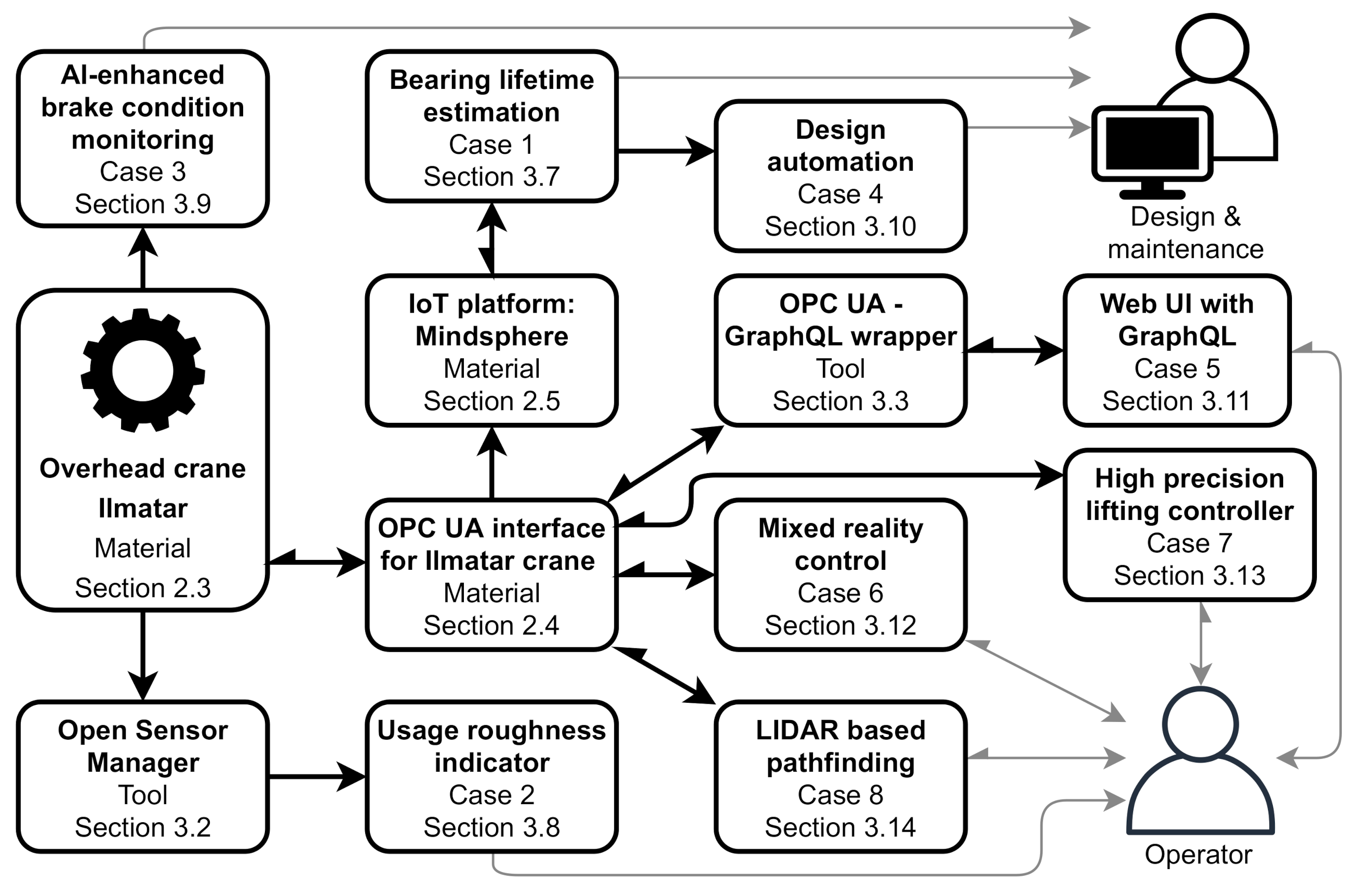
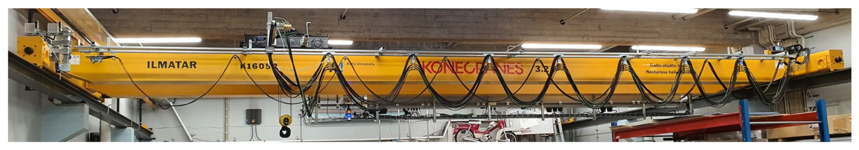
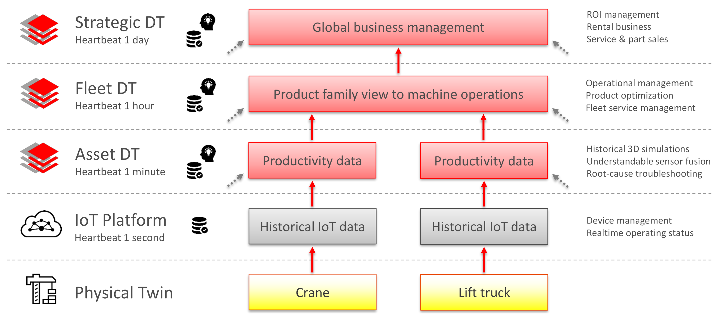
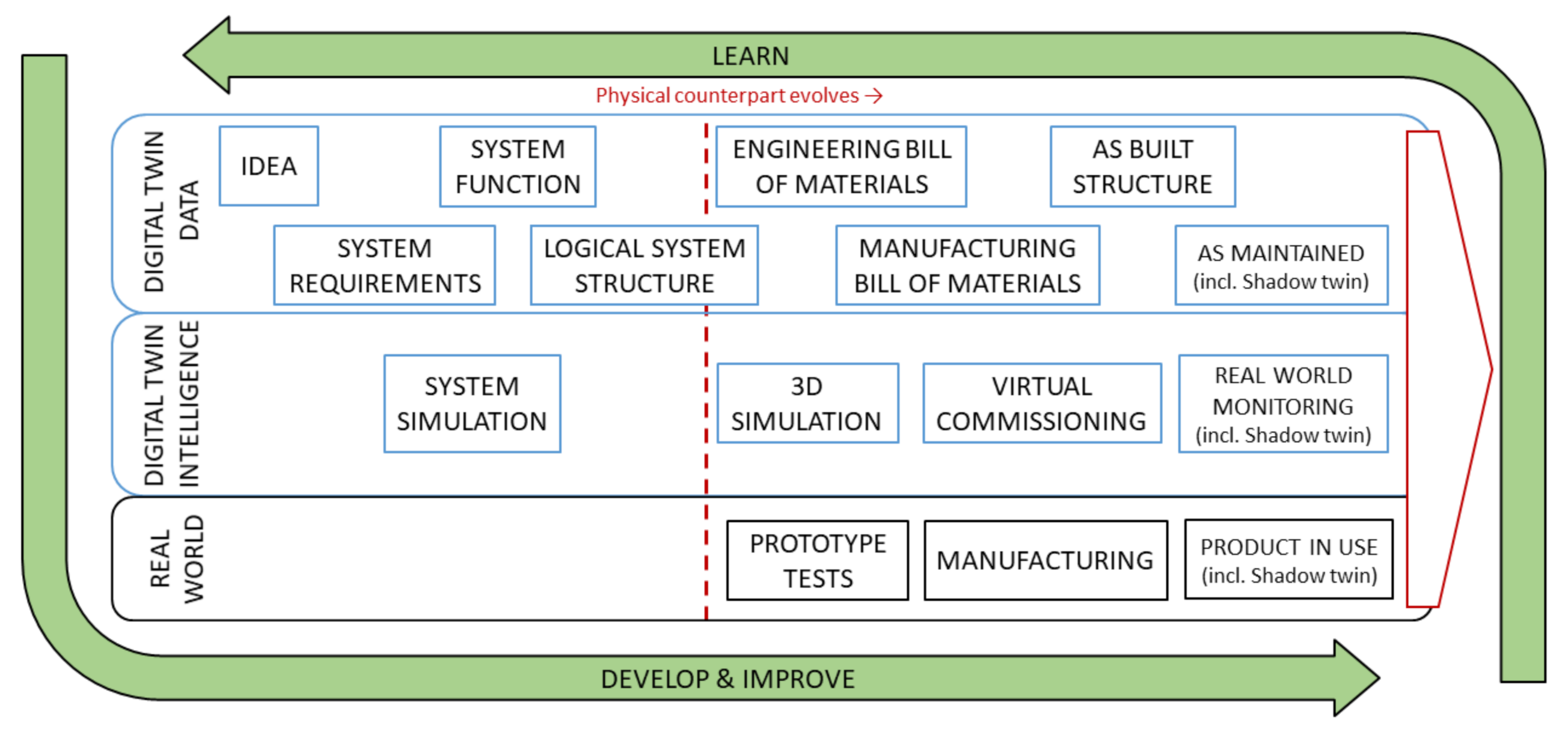
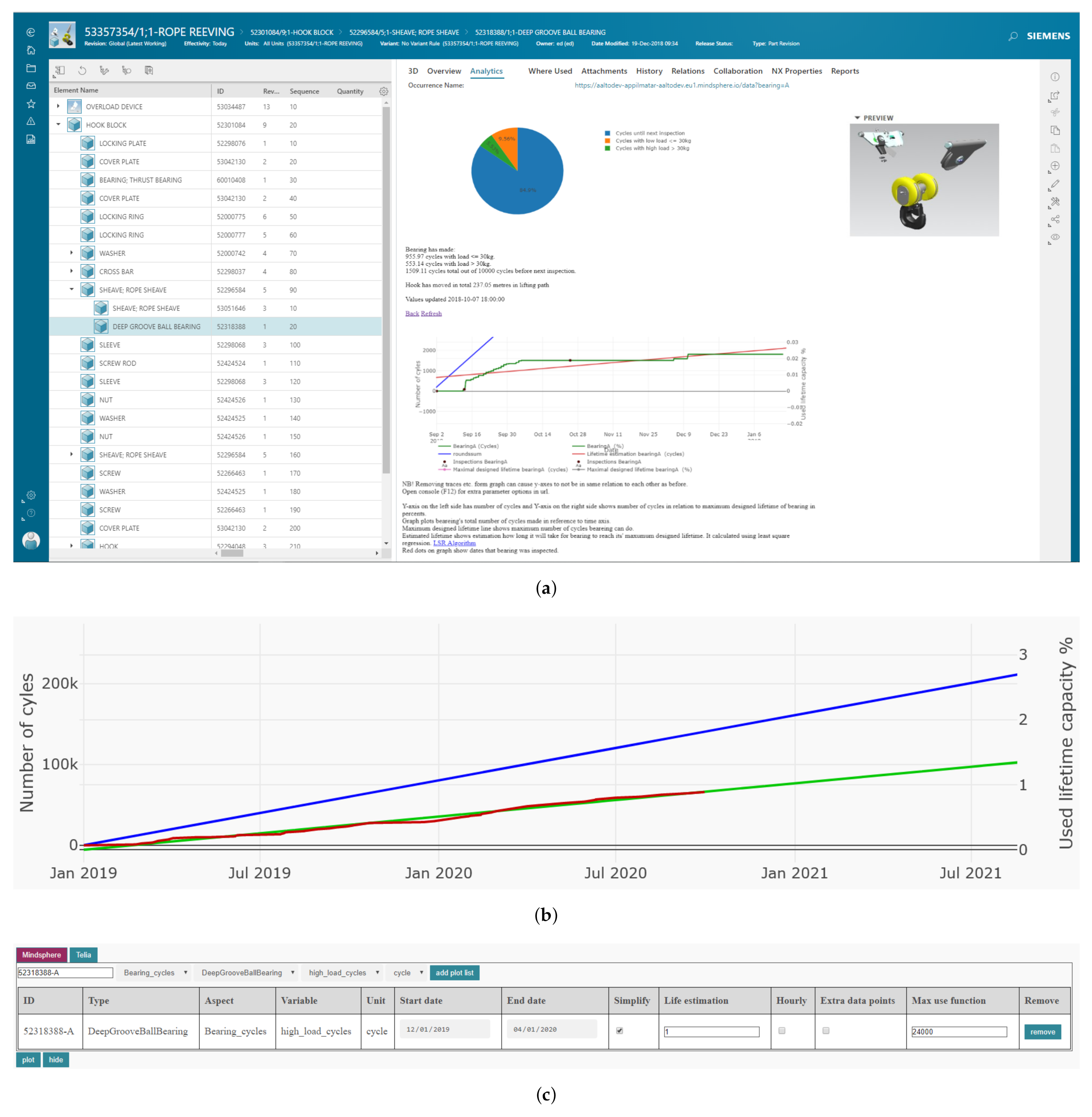
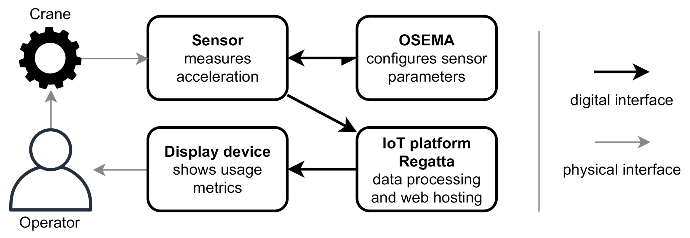
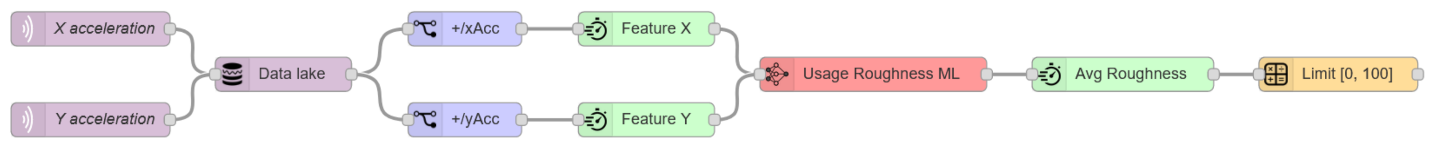
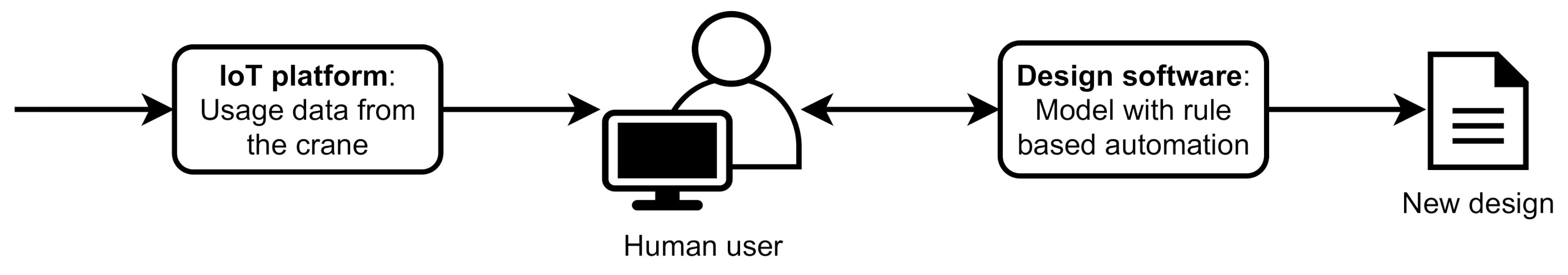
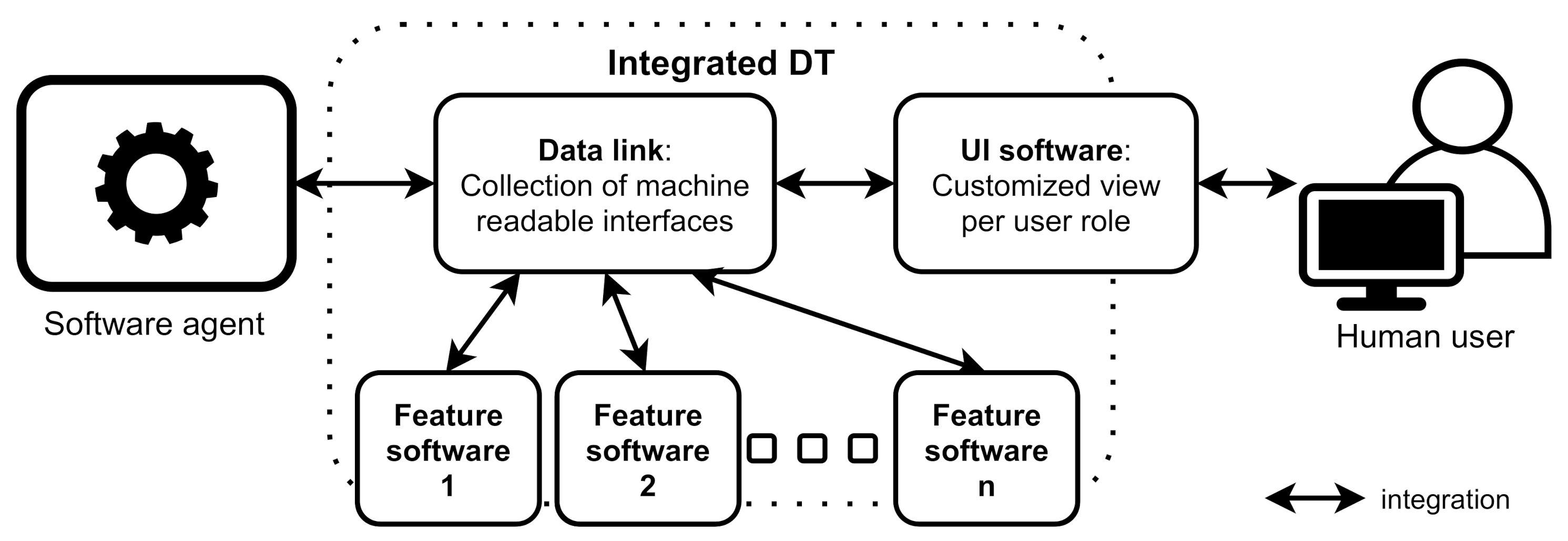
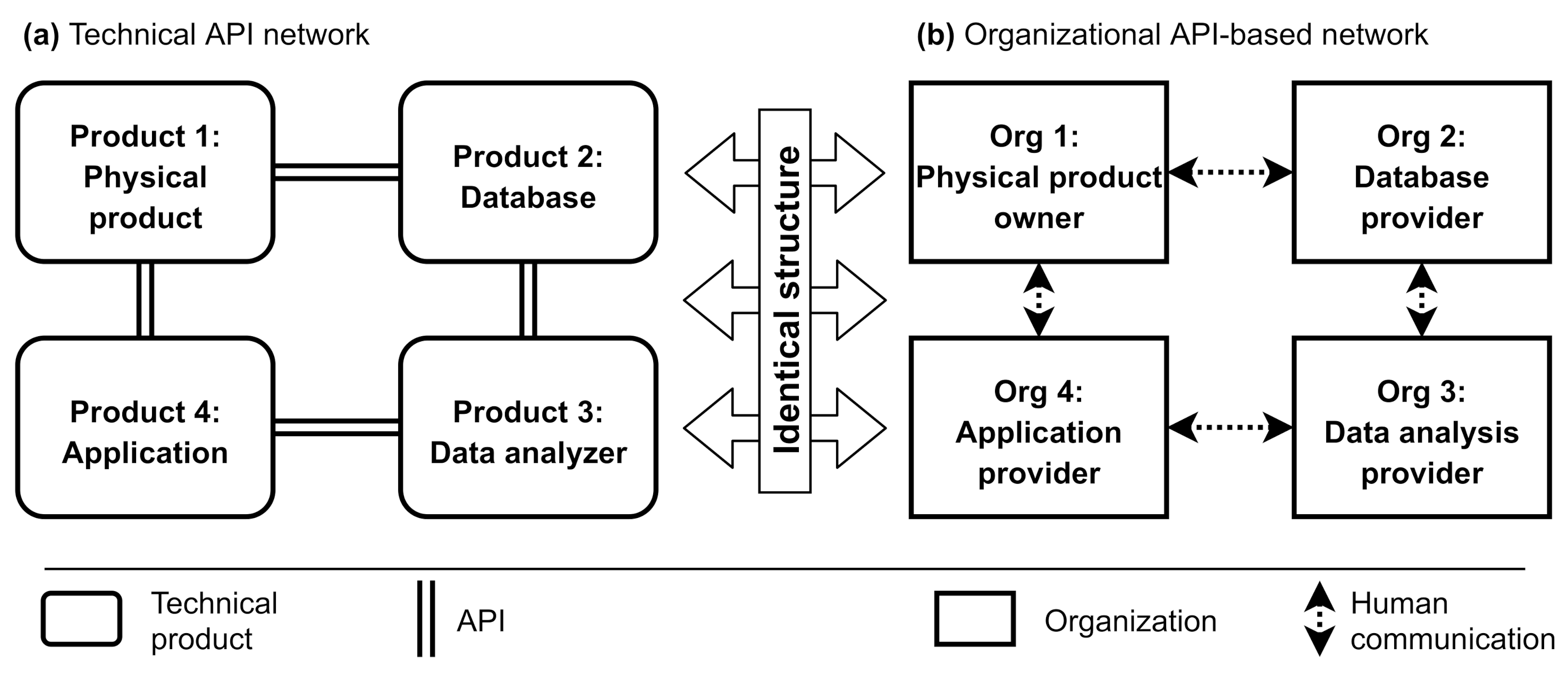
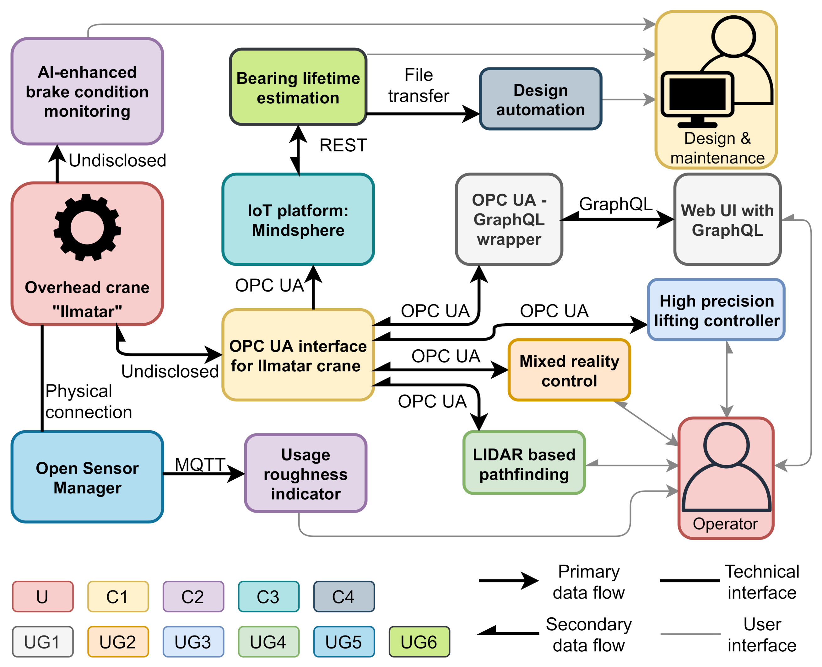
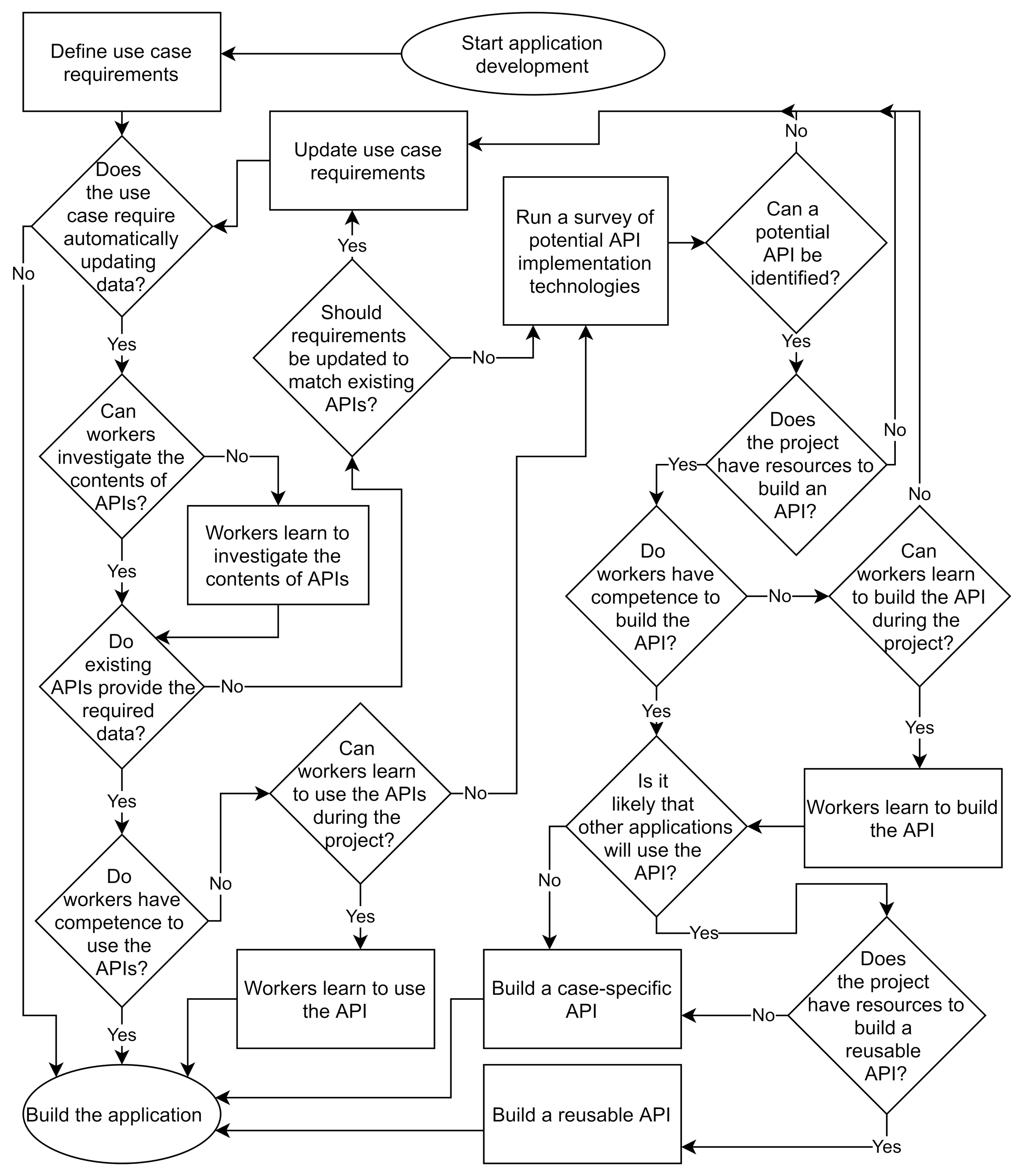