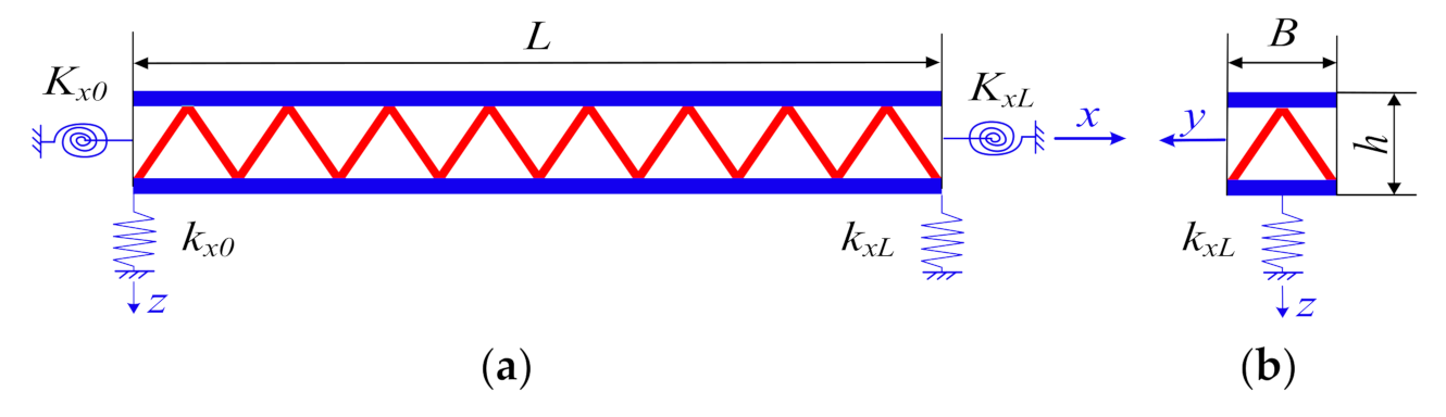
Figure 1.
Schematic diagram of lattice sandwich beams with arbitrary boundary conditions: (a) The structural parameters of the structural system. (b) The cross-sectional view of the structural system. (c) The kinematical parameters of the system.
Figure 1.
Schematic diagram of lattice sandwich beams with arbitrary boundary conditions: (a) The structural parameters of the structural system. (b) The cross-sectional view of the structural system. (c) The kinematical parameters of the system.
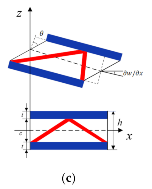
Figure 2.
Schematic diagram of three different lattice core layers. (a) Pyramidal truss core. (b) Tetrahedral truss core. (c) 3D-Kagome truss core.
Figure 2.
Schematic diagram of three different lattice core layers. (a) Pyramidal truss core. (b) Tetrahedral truss core. (c) 3D-Kagome truss core.
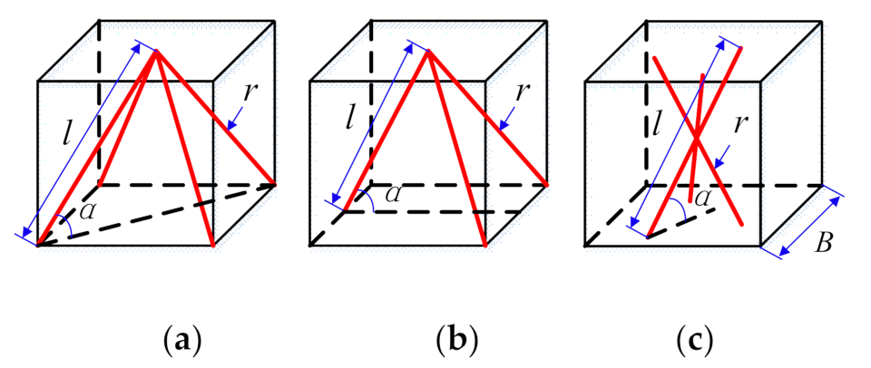
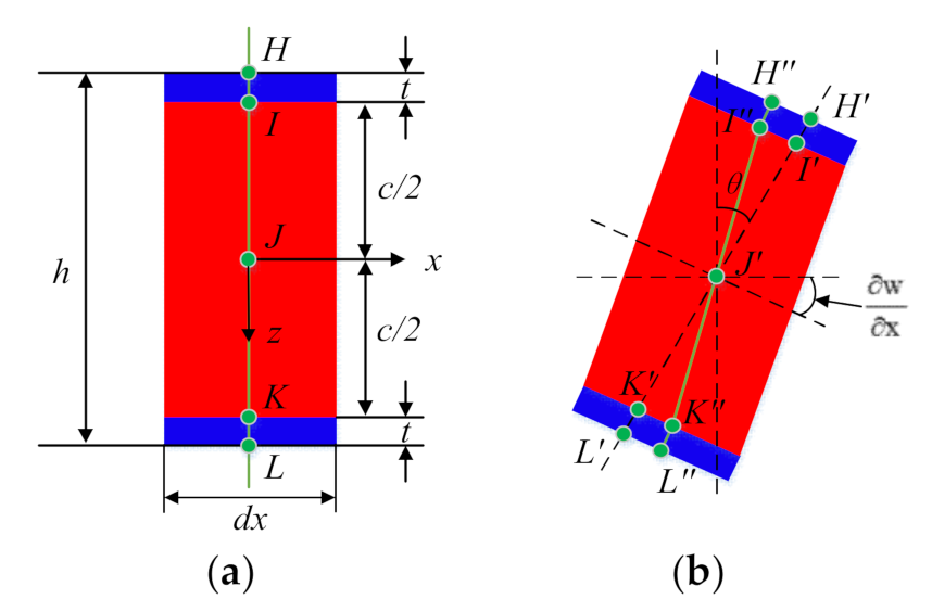
Figure 3.
Deformation of the equivalent lattice sandwich beam. (a) before deformation (b) after deformation.
Figure 3.
Deformation of the equivalent lattice sandwich beam. (a) before deformation (b) after deformation.
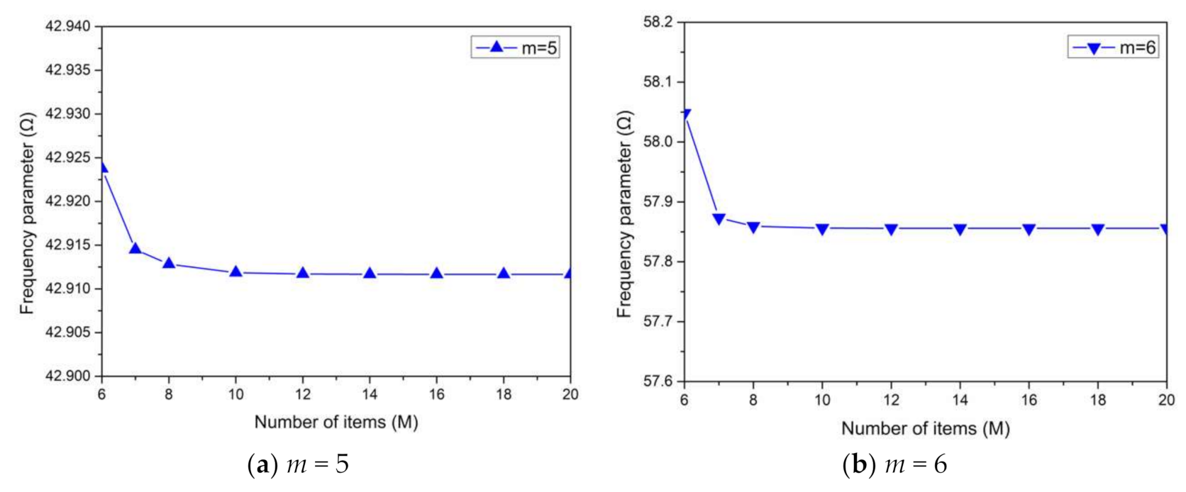
Figure 4.
Frequency parameters Ω for different numbers of items in the lattice sandwich beam with a pyramidal lattice core.
Figure 4.
Frequency parameters Ω for different numbers of items in the lattice sandwich beam with a pyramidal lattice core.
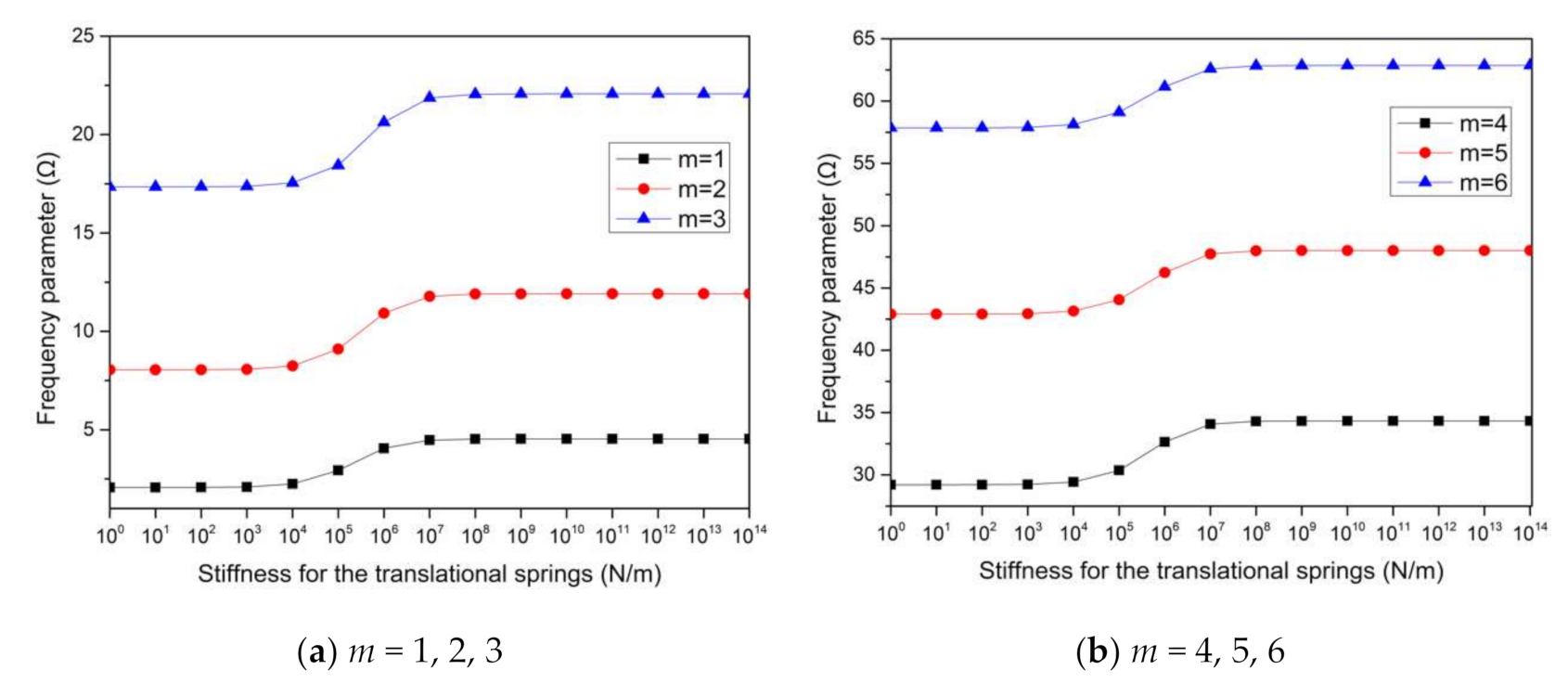
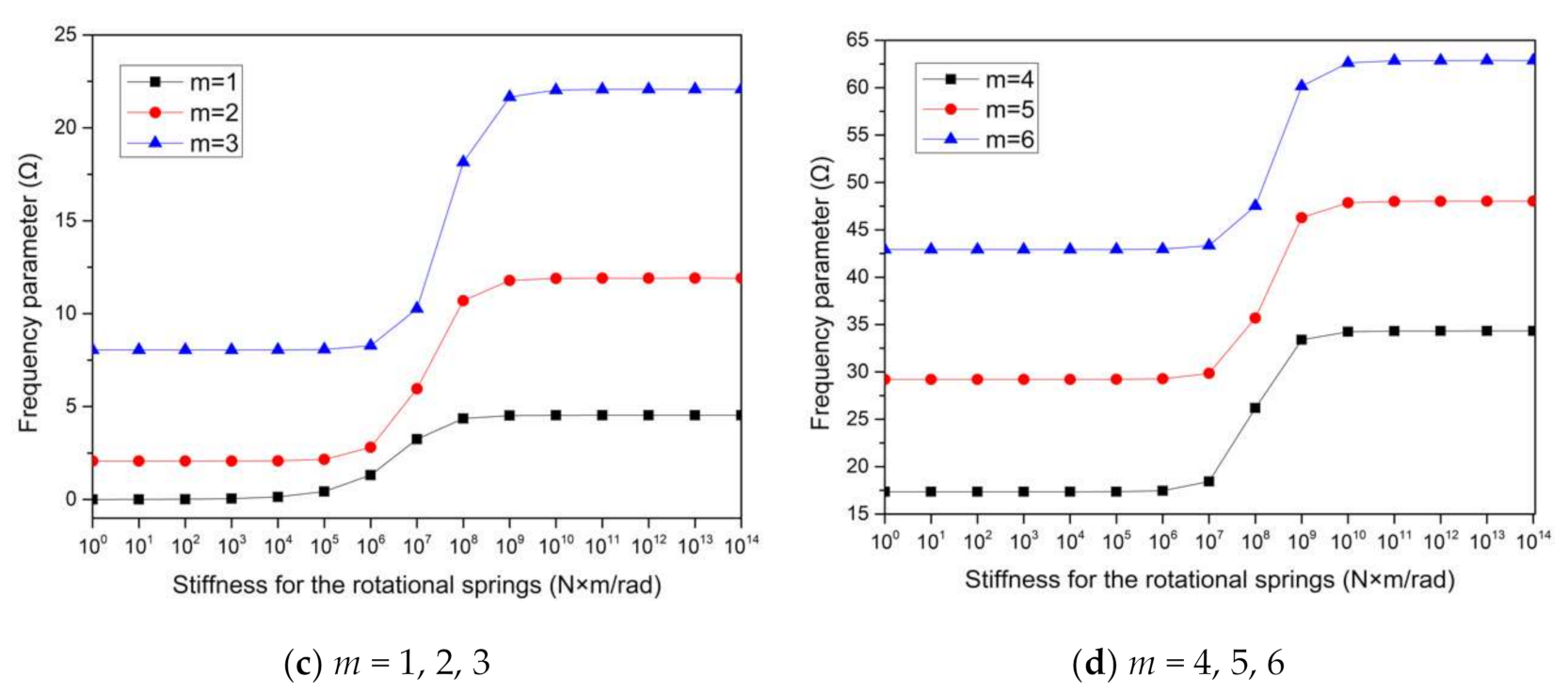
Figure 5.
Relationships of frequency parameters Ω with restraint spring stiffness of the lattice sandwich beam with a pyramidal lattice core.
Figure 5.
Relationships of frequency parameters Ω with restraint spring stiffness of the lattice sandwich beam with a pyramidal lattice core.
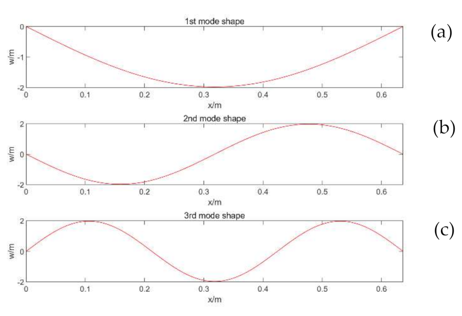
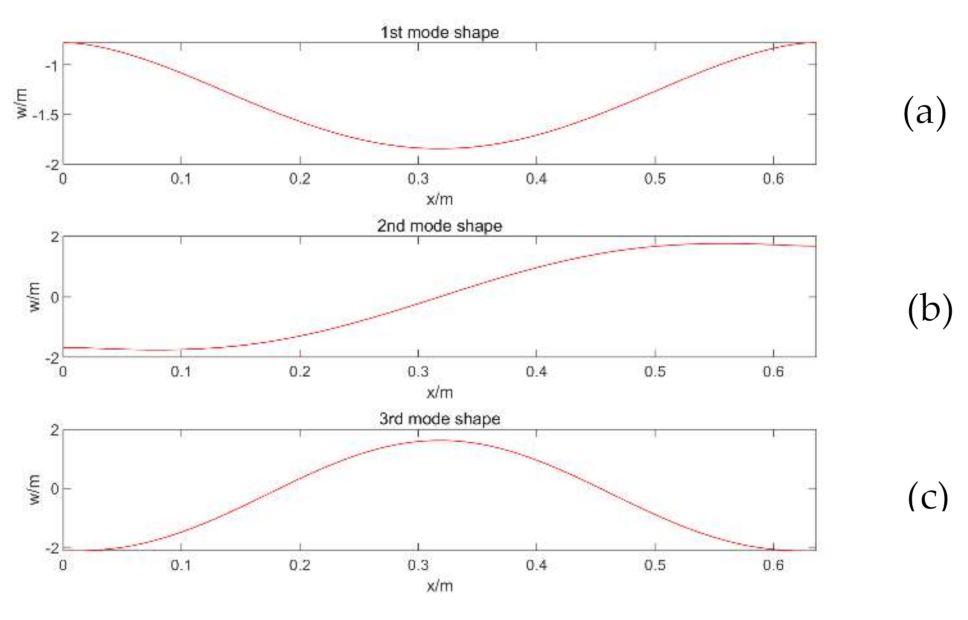
Figure 6.
Three initial mode shapes of the SS-SS lattice sandwich beam. (a) First mode shape, (b) Second mode shape and (c) Third mode shape.
Figure 6.
Three initial mode shapes of the SS-SS lattice sandwich beam. (a) First mode shape, (b) Second mode shape and (c) Third mode shape.
Figure 7.
Three initial mode shapes of the E3-E3 lattice sandwich beam. (a) First mode shape, (b) Second mode shape and (c) Third mode shape.
Figure 7.
Three initial mode shapes of the E3-E3 lattice sandwich beam. (a) First mode shape, (b) Second mode shape and (c) Third mode shape.
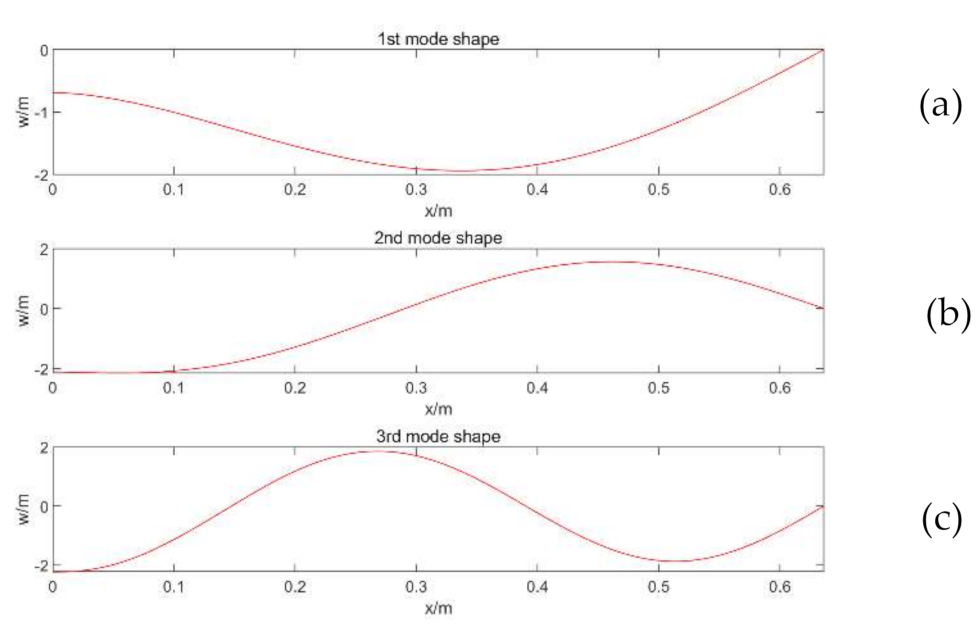
Figure 8.
Three initial mode shapes of the E3-SS lattice sandwich beam. (a) First mode shape, (b) Second mode shape and (c) Third mode shape.
Figure 8.
Three initial mode shapes of the E3-SS lattice sandwich beam. (a) First mode shape, (b) Second mode shape and (c) Third mode shape.
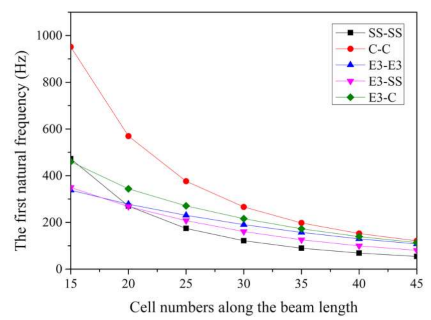
Figure 9.
Effect of the beam length on the first natural frequency of the pyramidal truss-core sandwich beam under arbitrary boundary conditions.
Figure 9.
Effect of the beam length on the first natural frequency of the pyramidal truss-core sandwich beam under arbitrary boundary conditions.
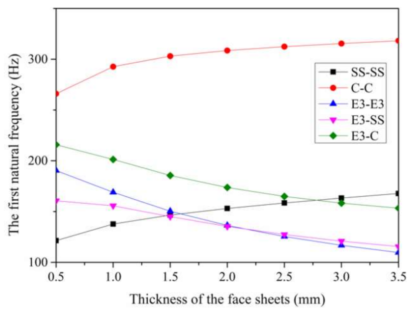
Figure 10.
Effect of the panel thickness on the first natural frequency of the pyramidal truss-core sandwich beam under arbitrary boundary conditions.
Figure 10.
Effect of the panel thickness on the first natural frequency of the pyramidal truss-core sandwich beam under arbitrary boundary conditions.
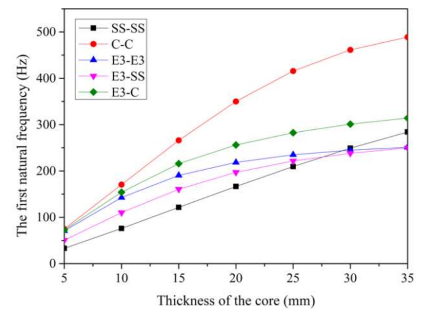
Figure 11.
Effect of the core height on the first natural frequency of the pyramidal truss-core sandwich beam under arbitrary boundary conditions.
Figure 11.
Effect of the core height on the first natural frequency of the pyramidal truss-core sandwich beam under arbitrary boundary conditions.
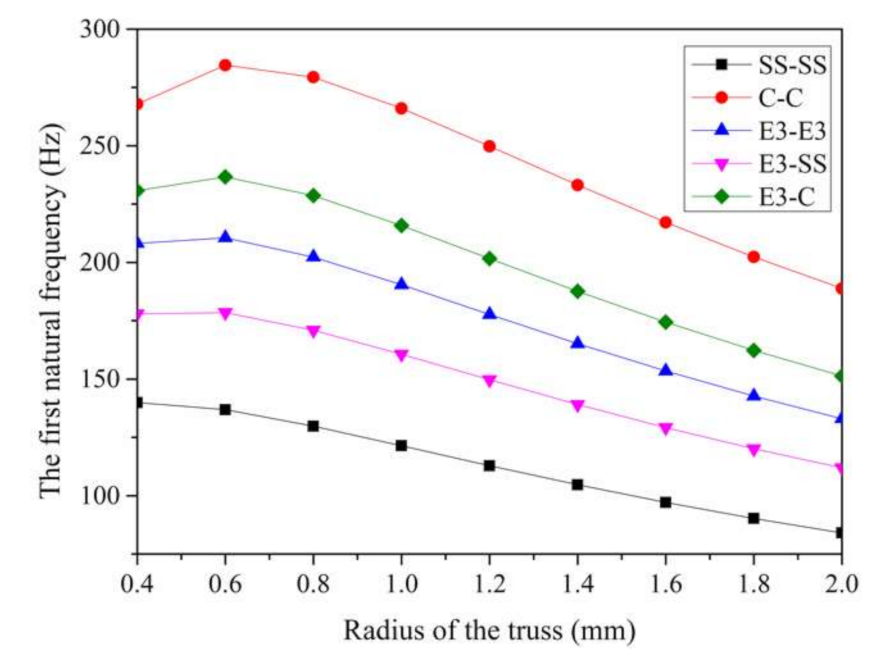
Figure 12.
Effect of the truss radius on the first natural frequency of the pyramidal truss-core sandwich beam under arbitrary boundary conditions.
Figure 12.
Effect of the truss radius on the first natural frequency of the pyramidal truss-core sandwich beam under arbitrary boundary conditions.
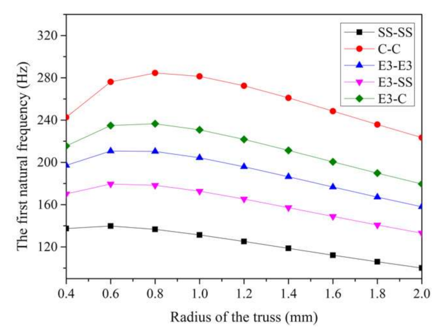
Figure 13.
Effect of the truss radius on the first natural frequency of the tetrahedral truss-core sandwich beam under arbitrary boundary conditions.
Figure 13.
Effect of the truss radius on the first natural frequency of the tetrahedral truss-core sandwich beam under arbitrary boundary conditions.
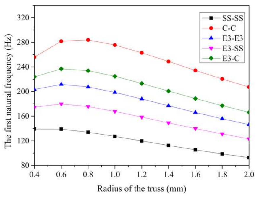
Figure 14.
Effect of the truss radius on the first natural frequency of the 3D–Kagome truss-core sandwich beam under arbitrary boundary conditions.
Figure 14.
Effect of the truss radius on the first natural frequency of the 3D–Kagome truss-core sandwich beam under arbitrary boundary conditions.
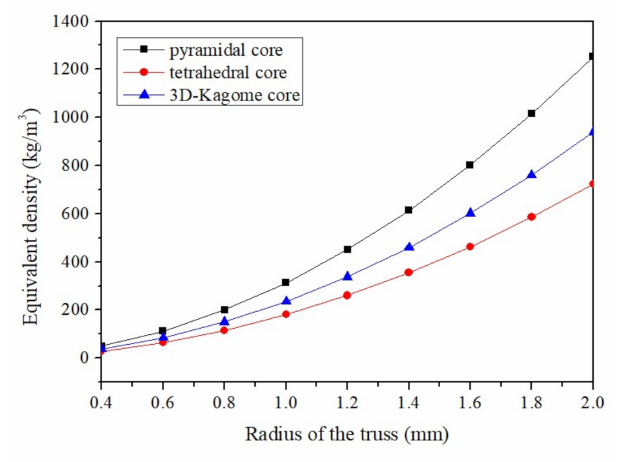
Figure 15.
The relationship between truss radius and the equivalent density of the lattice sandwich beam under different truss cores.
Figure 15.
The relationship between truss radius and the equivalent density of the lattice sandwich beam under different truss cores.
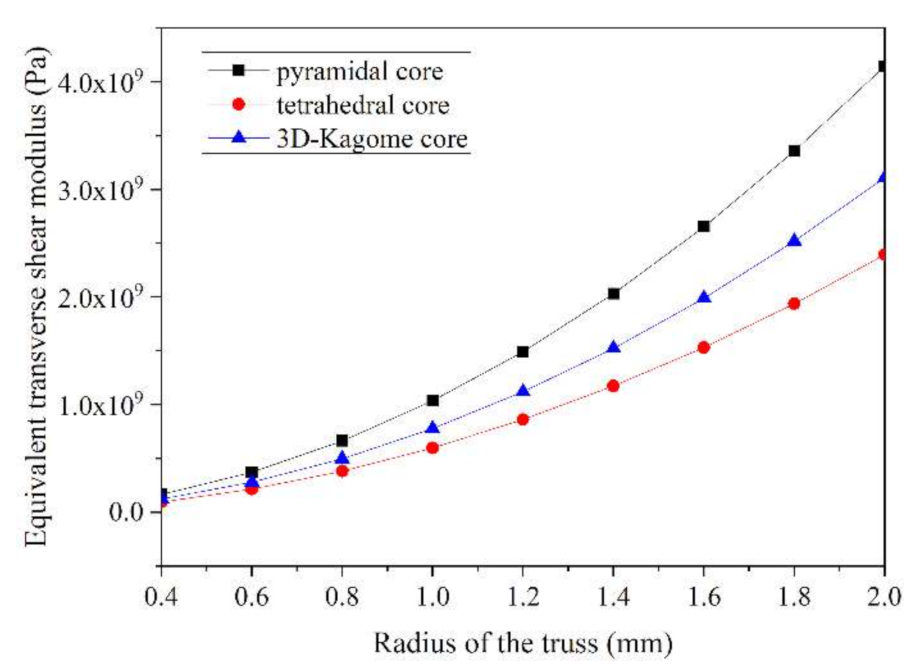
Figure 16.
The relationship between truss radius and the equivalent transverse shear modulus of the lattice sandwich beams under different truss cores.
Figure 16.
The relationship between truss radius and the equivalent transverse shear modulus of the lattice sandwich beams under different truss cores.
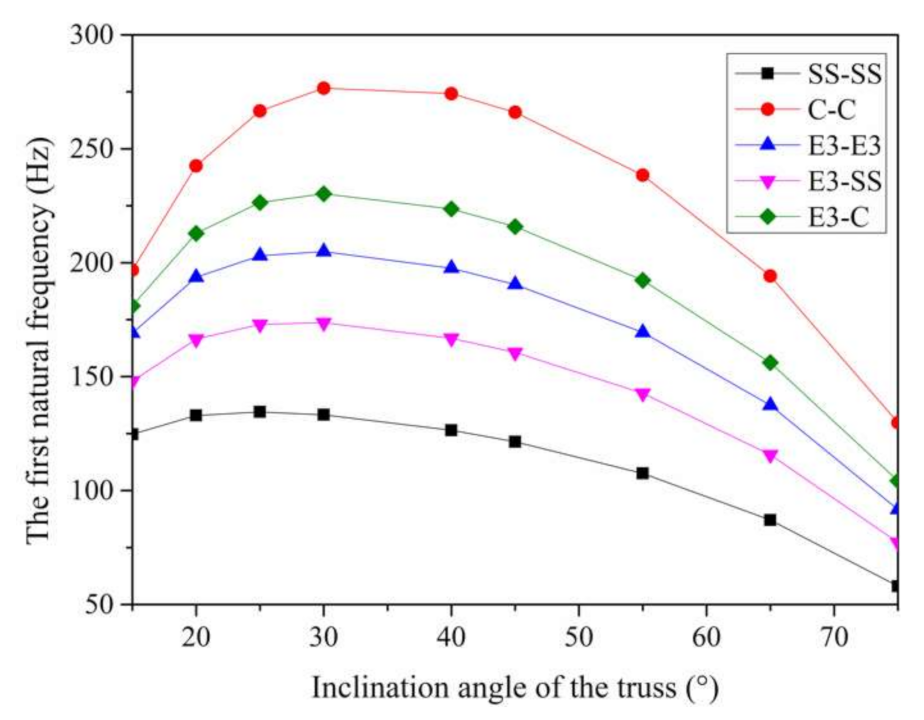
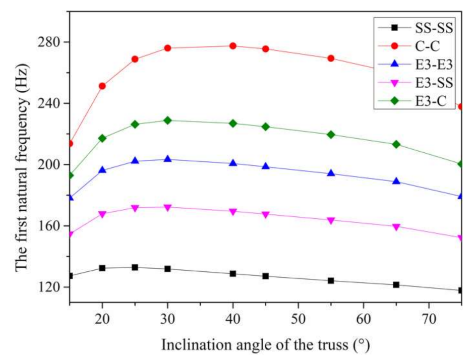
Figure 17.
Effect of the inclination angle on the first natural frequency of the pyramidal truss-core sandwich beam under arbitrary boundary conditions.
Figure 17.
Effect of the inclination angle on the first natural frequency of the pyramidal truss-core sandwich beam under arbitrary boundary conditions.
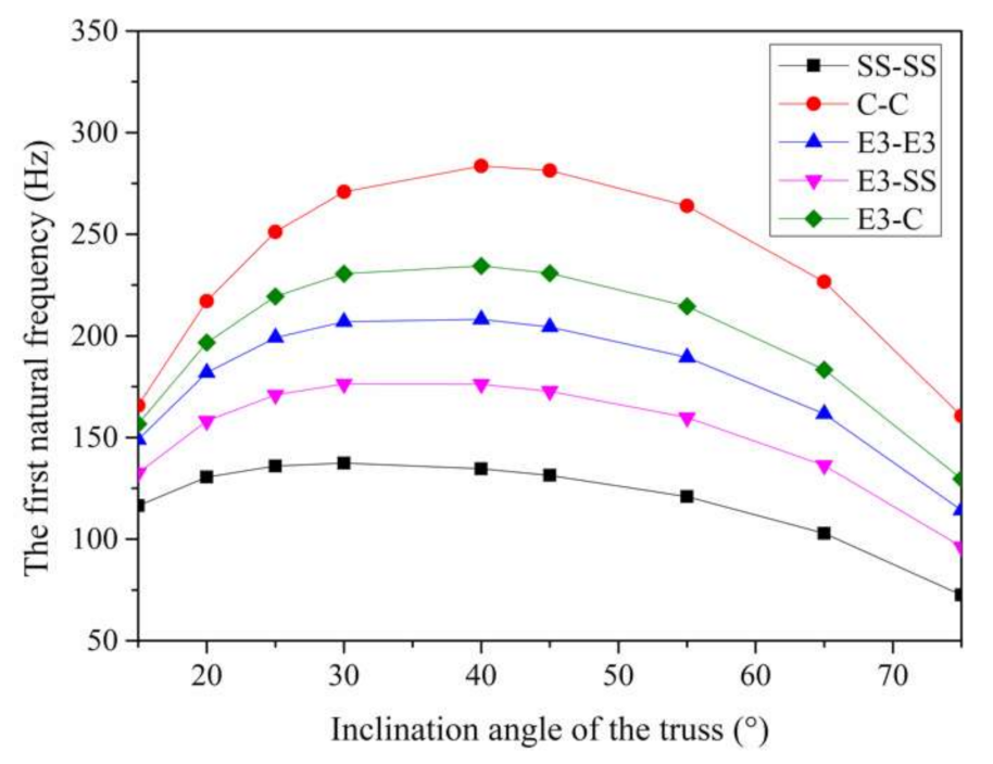
Figure 18.
Effect of the inclination angle on the first natural frequency of the tetrahedral truss-core sandwich beam under arbitrary boundary conditions.
Figure 18.
Effect of the inclination angle on the first natural frequency of the tetrahedral truss-core sandwich beam under arbitrary boundary conditions.
Figure 19.
Effect of the inclination angle on the first natural frequency of the 3D–Kagome truss-core sandwich beam under arbitrary boundary conditions.
Figure 19.
Effect of the inclination angle on the first natural frequency of the 3D–Kagome truss-core sandwich beam under arbitrary boundary conditions.
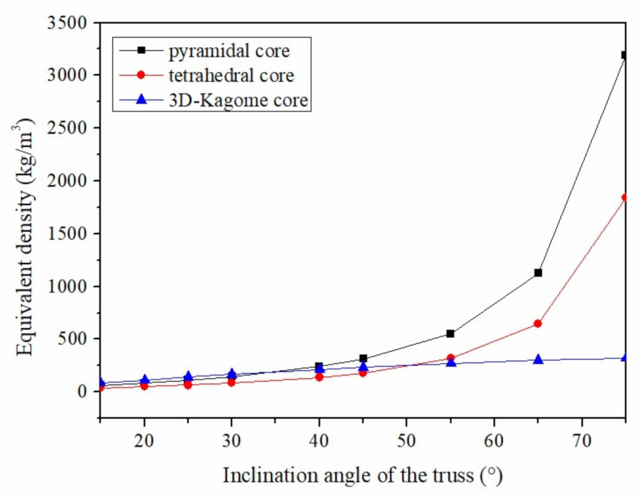
Figure 20.
The relationship between the inclination angle and the equivalent density of lattice sandwich beams under different truss cores.
Figure 20.
The relationship between the inclination angle and the equivalent density of lattice sandwich beams under different truss cores.
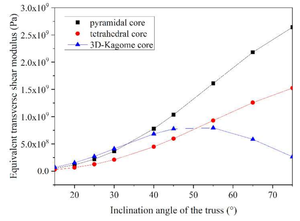
Figure 21.
The relationship between the inclination angle and the equivalent transverse shear modulus of lattice sandwich beams under different truss cores.
Figure 21.
The relationship between the inclination angle and the equivalent transverse shear modulus of lattice sandwich beams under different truss cores.
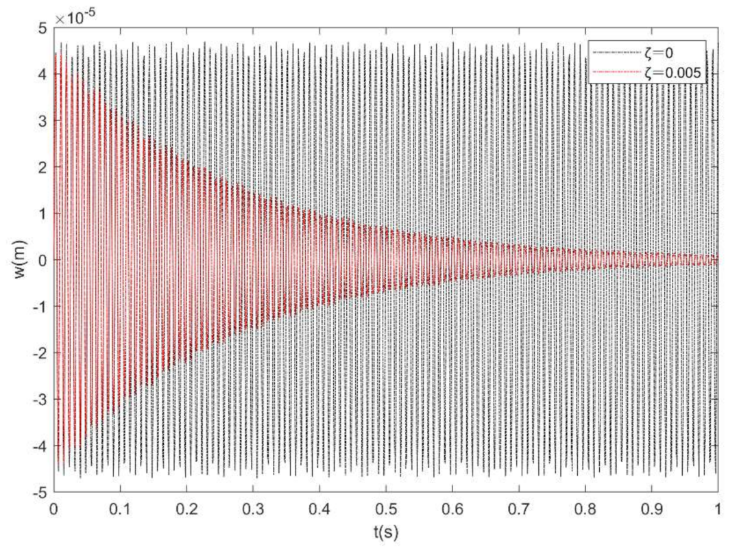
Figure 22.
Time-response history at the middle point of the lattice sandwich beam, when ζ = 0 and ζ = 0.005.
Figure 22.
Time-response history at the middle point of the lattice sandwich beam, when ζ = 0 and ζ = 0.005.
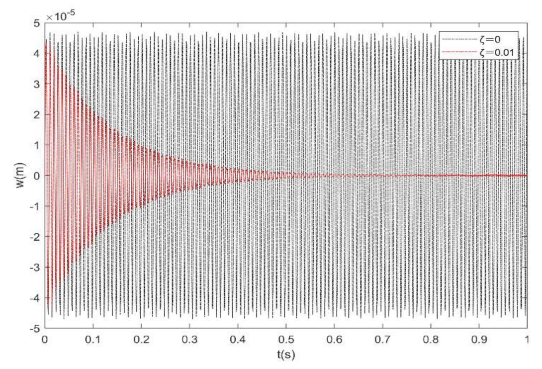
Figure 23.
Time-response history at the middle point of the lattice sandwich beam, when ζ = 0 and ζ = 0.01.
Figure 23.
Time-response history at the middle point of the lattice sandwich beam, when ζ = 0 and ζ = 0.01.
Table 1.
Comparison of the natural frequencies for the lattice sandwich beam with a pyramidal lattice core (Hz).
Table 1.
Comparison of the natural frequencies for the lattice sandwich beam with a pyramidal lattice core (Hz).
| Boundary Condition | Mode | Hwu et al. [19] | Lou et al. [21] | Xu et al. [27] | Present Results
(M = 10) | Error |
|---|
| Clamped ends(CC–CC) | 1 | 264.99 | 265.44 | 265.21 | 266.02 | −0.22% |
| 2 | 693.24 | 695.72 | 694.48 | 699.10 | −0.49% |
| 3 | 1278.8 | 1286.1 | 1282.2 | 1295.25 | −0.71% |
| 4 | 1977.7 | 1993.7 | 1986.9 | 2014.54 | −1.05% |
| 5 | 2756.9 | 2786.3 | 2764.5 | 2817.91 | −1.13% |
| Simply supported ends(SS–SS) | 1 | 121.37 | 121.42 | 121.33 | 121.42 | 0.00% |
| 2 | 471.66 | 472.30 | 472.1 | 472.31 | 0.00% |
| 3 | 1014.9 | 1017.9 | 1014.6 | 1017.95 | 0.00% |
| 4 | 1705.6 | 1714.2 | 1702.9 | 1714.18 | 0.00% |
| 5 | 2500.0 | 2518.4 | 2506.3 | 2518.40 | 0.00% |
| Clamped−free ends(C–F) | 1 | 43.468 | 43.572 | 43.63 | 43.48 | 0.21% |
| 2 | 265.01 | 266.40 | 265.76 | 265.49 | 0.34% |
| 3 | 712.04 | 718.13 | 715.61 | 715.08 | 0.42% |
| 4 | 1321.2 | 1337.5 | 1333.7 | 1331.15 | 0.48% |
| 5 | 2051.8 | 2085.7 | 2033.1 | 2074.36 | 0.54% |
Table 2.
Convergence analysis of for a SS–SS sandwich beam with a pyramidal lattice core, as M increases.
Table 2.
Convergence analysis of for a SS–SS sandwich beam with a pyramidal lattice core, as M increases.
| M | Model Sequence |
|---|
| 1 | 2 | 3 | 4 | 5 | 6 |
|---|
| 6 | 2.0689 | 8.0478 | 17.3451 | 29.2085 | 42.9238 | 58.0482 |
| 8 | 2.0689 | 8.0478 | 17.3451 | 29.2085 | 42.9145 | 57.8734 |
| 10 | 2.0689 | 8.0478 | 17.3451 | 29.2085 | 42.9128 | 57.8594 |
| 12 | 2.0689 | 8.0478 | 17.3451 | 29.2085 | 42.9118 | 57.8562 |
| 14 | 2.0689 | 8.0478 | 17.3451 | 29.2085 | 42.9117 | 57.8560 |
| 16 | 2.0689 | 8.0478 | 17.3451 | 29.2085 | 42.9117 | 57.8559 |
Table 3.
The values of spring rigidity under arbitrary boundary conditions.
Table 3.
The values of spring rigidity under arbitrary boundary conditions.
| Boundary Conditions | F | C | SS | E1 | E2 | E3 |
|---|
| ki (i = 0, L) | 0 | 1014 | 1014 | 105 | 106 | 107 |
| Ki (i = 0, L) | 0 | 1014 | 0 | 107 | 108 | 109 |
Table 4.
Frequency parameters Ω for lattice sandwich beams with several classical boundary conditions.
Table 4.
Frequency parameters Ω for lattice sandwich beams with several classical boundary conditions.
| Boundary Conditions | Mode Sequence |
|---|
| 1 | 2 | 3 | 4 | 5 | 6 |
|---|
| F–F | 0.0000 | 0.0019 | 4.6697 | 12.4591 | 23.3257 | 36.4479 |
| SS–SS | 2.0689 | 8.0478 | 17.3451 | 29.2085 | 42.9118 | 57.8562 |
| C–C | 4.5327 | 11.9122 | 22.0701 | 34.3264 | 48.0153 | 62.8635 |
| SS–F | 0.0009 | 3.2241 | 10.1398 | 20.2331 | 32.7395 | 46.9466 |
| C–F | 0.7408 | 4.5238 | 12.1844 | 22.6818 | 35.3457 | 49.5428 |
| SS–C | 3.1828 | 9.9286 | 19.7000 | 31.7739 | 45.5013 | 60.3664 |
Table 5.
Frequency parameters Ω for lattice sandwich beams with several elastic boundary conditions.
Table 5.
Frequency parameters Ω for lattice sandwich beams with several elastic boundary conditions.
| Boundary Conditions | Mode Sequence |
|---|
| 1 | 2 | 3 | 4 | 5 | 6 |
|---|
| E1–E1 | 0.4264 | 2.1411 | 8.0147 | 17.2445 | 29.0461 | 42.6961 |
| E2–E2 | 1.3112 | 2.8063 | 8.2706 | 17.4394 | 29.2536 | 42.9313 |
| E3–E3 | 3.2448 | 5.9553 | 10.2655 | 18.4350 | 29.8442 | 43.3382 |
| E1–E2 | 0.8600 | 2.5327 | 8.1444 | 17.3421 | 29.1498 | 42.8136 |
| E1–E3 | 1.2028 | 4.5804 | 9.3204 | 17.8623 | 29.4499 | 43.0185 |
| E2–E3 | 1.7983 | 4.7050 | 9.4148 | 17.9553 | 29.5525 | 43.1358 |
Table 6.
Frequency parameters Ω for lattice sandwich beams with arbitrary boundary conditions.
Table 6.
Frequency parameters Ω for lattice sandwich beams with arbitrary boundary conditions.
| Boundary Conditions | Mode Sequence |
|---|
| 1 | 2 | 3 | 4 | 5 | 6 |
|---|
| E1–F | 0.2869 | 1.2339 | 6.2327 | 14.7937 | 26.1570 | 39.5668 |
| E2–F | 0.6171 | 1.7714 | 6.3907 | 14.8940 | 26.2590 | 39.6822 |
| E–3F | 0.7272 | 3.6098 | 7.8701 | 15.5133 | 26.5960 | 39.9047 |
| E1–C | 1.2617 | 6.1255 | 14.4416 | 25.4206 | 38.3692 | 52.6972 |
| E2–C | 1.8772 | 6.2805 | 14.5400 | 25.5202 | 38.4800 | 52.8244 |
| E3–C | 3.6773 | 7.7494 | 15.1622 | 25.8595 | 38.7019 | 52.9903 |
| E1–SS | 0.6716 | 4.6038 | 12.2935 | 22.9374 | 35.7759 | 50.1410 |
| E2–SS | 1.3834 | 4.8051 | 12.3983 | 23.0363 | 35.8864 | 50.2658 |
| E3–SS | 2.7371 | 6.5917 | 13.1531 | 23.4202 | 36.1301 | 50.4421 |
Table 7.
Comparison of the natural frequencies of pyramidal truss-core sandwich beams of different beam lengths under arbitrary boundary conditions (Hz).
Table 7.
Comparison of the natural frequencies of pyramidal truss-core sandwich beams of different beam lengths under arbitrary boundary conditions (Hz).
| Cell Numbers | Arbitrary Boundary Conditions |
|---|
| SS–SS | C–C | E3–E3 | E3–SS | E3–C |
|---|
| 15 | 472.3090 | 951.5135 | 337.8441 | 349.2931 | 459.7782 |
| 20 | 269.9761 | 569.5114 | 278.0257 | 267.9476 | 343.5740 |
| 25 | 174.1084 | 376.1836 | 230.4454 | 207.4917 | 270.8658 |
| 30 | 121.4175 | 266.0154 | 190.4328 | 160.6320 | 215.8123 |
| 35 | 89.4326 | 197.6274 | 156.9436 | 125.4781 | 172.5897 |
| 40 | 68.5858 | 152.4518 | 129.5811 | 99.5839 | 139.1626 |
| 45 | 54.2533 | 121.0526 | 107.6502 | 80.4497 | 113.5873 |
Table 8.
Comparison of the natural frequencies of pyramidal truss-core sandwich beams of different panel thicknesses under arbitrary boundary conditions (Hz).
Table 8.
Comparison of the natural frequencies of pyramidal truss-core sandwich beams of different panel thicknesses under arbitrary boundary conditions (Hz).
| Panel Thicknesses (mm) | Arbitrary Boundary Conditions |
|---|
| SS–SS | C–C | E3–E3 | E3–SS | E3–C |
|---|
| 0.5 | 121.4175 | 266.0154 | 190.4328 | 160.6320 | 215.8123 |
| 1 | 137.7297 | 292.6634 | 168.9821 | 155.7359 | 201.3014 |
| 1.5 | 146.5784 | 302.9722 | 150.4007 | 145.0440 | 185.5933 |
| 2 | 153.0482 | 308.5381 | 136.3312 | 135.3830 | 173.7080 |
| 2.5 | 158.4541 | 312.3427 | 125.4501 | 127.4007 | 164.9065 |
| 3 | 163.2901 | 315.3960 | 116.7719 | 120.8833 | 158.3260 |
| 3.5 | 167.7836 | 318.1906 | 109.6617 | 115.5383 | 153.3543 |
Table 9.
Comparison of the natural frequencies of pyramidal truss-core sandwich beams of different core heights under arbitrary boundary conditions (Hz).
Table 9.
Comparison of the natural frequencies of pyramidal truss-core sandwich beams of different core heights under arbitrary boundary conditions (Hz).
Core Height
(mm) | Arbitrary Boundary Conditions |
|---|
| SS–SS | C–C | E3–E3 | E3–SS | E3–C |
|---|
| 5 | 32.9684 | 74.7245 | 70.7994 | 50.4886 | 72.6211 |
| 10 | 76.0519 | 170.5798 | 142.6226 | 110.1543 | 154.1021 |
| 15 | 121.4175 | 266.0154 | 190.4328 | 160.6320 | 215.8123 |
| 20 | 166.4761 | 349.9606 | 218.4888 | 197.0480 | 256.0741 |
| 25 | 209.5006 | 415.6572 | 234.9471 | 221.5729 | 282.5575 |
| 30 | 249.0683 | 461.2186 | 244.8919 | 238.1765 | 300.9681 |
| 35 | 284.0671 | 488.7007 | 251.0252 | 249.8877 | 314.1467 |
Table 10.
Comparisons of the natural frequencies of pyramidal truss-core sandwich beams with different truss radius under arbitrary boundary conditions (Hz).
Table 10.
Comparisons of the natural frequencies of pyramidal truss-core sandwich beams with different truss radius under arbitrary boundary conditions (Hz).
Truss Radius
(mm) | Arbitrary Boundary Conditions |
|---|
| SS–SS | C–C | E3–E3 | E3–SS | E3–C |
|---|
| 0.4 | 139.9091 | 267.8756 | 208.1397 | 177.9489 | 230.7810 |
| 0.6 | 136.8992 | 284.5443 | 210.5608 | 178.4970 | 236.6766 |
| 0.8 | 129.8016 | 279.3969 | 202.2866 | 170.9090 | 228.6271 |
| 1 | 121.4175 | 266.0154 | 190.4328 | 160.6320 | 215.8123 |
| 1.2 | 112.8727 | 249.7781 | 177.6603 | 149.7228 | 201.6419 |
| 1.4 | 104.6991 | 233.1444 | 165.1523 | 139.1051 | 187.6189 |
| 1.6 | 97.1334 | 217.1685 | 153.4348 | 129.1895 | 174.4136 |
| 1.8 | 90.2537 | 202.3523 | 142.7060 | 120.1265 | 162.2863 |
| 2 | 84.0553 | 188.8378 | 132.9978 | 111.9348 | 151.2920 |
Table 11.
Comparisons of the natural frequencies of tetrahedral truss-core sandwich beams with different truss radii under arbitrary boundary conditions (Hz).
Table 11.
Comparisons of the natural frequencies of tetrahedral truss-core sandwich beams with different truss radii under arbitrary boundary conditions (Hz).
Radius of
the Truss (mm) | Arbitrary Boundary Conditions |
|---|
| SS–SS | C–C | E3–E3 | E3–SS | E3–C |
|---|
| 0.4 | 137.4313 | 242.6776 | 197.1684 | 170.1449 | 215.5373 |
| 0.6 | 139.8083 | 276.1559 | 210.7334 | 179.5651 | 234.8861 |
| 0.8 | 136.6687 | 284.5942 | 210.3639 | 178.2960 | 236.5277 |
| 1 | 131.3832 | 281.3776 | 204.3654 | 172.7485 | 230.7951 |
| 1.2 | 125.1822 | 272.4854 | 195.8814 | 165.3260 | 221.7693 |
| 1.4 | 118.6770 | 261.0067 | 186.3849 | 157.1637 | 211.3455 |
| 1.6 | 112.2116 | 248.4577 | 176.6567 | 148.8691 | 200.5202 |
| 1.8 | 105.9816 | 235.7920 | 167.1272 | 140.7789 | 189.8390 |
| 2 | 100.0916 | 223.4619 | 158.0284 | 133.0740 | 179.5965 |
Table 12.
Comparisons of the natural frequencies of 3D–Kagome truss-core sandwich beams with different truss radii under arbitrary boundary conditions (Hz).
Table 12.
Comparisons of the natural frequencies of 3D–Kagome truss-core sandwich beams with different truss radii under arbitrary boundary conditions (Hz).
Radius of
the Truss (mm) | Arbitrary Boundary Conditions |
|---|
| SS–SS | C–C | E3–E3 | E3–SS | E3–C |
|---|
| 0.4 | 139.0700 | 255.8957 | 203.3113 | 174.5988 | 223.8548 |
| 0.6 | 138.8832 | 281.7456 | 211.6004 | 179.8111 | 236.9097 |
| 0.8 | 133.8783 | 283.8063 | 207.4455 | 175.5245 | 233.8970 |
| 1 | 127.1032 | 275.5349 | 198.5927 | 167.6778 | 224.6977 |
| 1.2 | 119.7316 | 262.9310 | 187.9493 | 158.5026 | 213.0750 |
| 1.4 | 112.3501 | 248.7202 | 176.8671 | 149.0480 | 200.7555 |
| 1.6 | 105.2674 | 234.2966 | 166.0278 | 139.8470 | 188.6031 |
| 1.8 | 98.6351 | 220.3493 | 155.7685 | 131.1625 | 177.0474 |
| 2 | 92.5132 | 207.2480 | 146.2359 | 123.1070 | 166.2793 |
Table 13.
Comparisons of the natural frequencies of pyramidal truss-core sandwich beams with different inclination angles under arbitrary boundary conditions (Hz).
Table 13.
Comparisons of the natural frequencies of pyramidal truss-core sandwich beams with different inclination angles under arbitrary boundary conditions (Hz).
Inclination
Angle (°) | Arbitrary Boundary Conditions |
|---|
| SS–SS | C–C | E3–E3 | E3–SS | E3–C |
|---|
| 15 | 124.7301 | 196.8051 | 169.0734 | 148.0808 | 181.0930 |
| 20 | 132.9740 | 242.5085 | 193.6238 | 166.4510 | 212.8749 |
| 25 | 134.5389 | 266.5863 | 203.0309 | 172.9508 | 226.4270 |
| 30 | 133.2646 | 276.5761 | 204.8588 | 173.6883 | 230.2152 |
| 40 | 126.4712 | 274.1745 | 197.6094 | 166.8468 | 223.5877 |
| 45 | 121.4175 | 266.0154 | 190.4328 | 160.6320 | 215.8123 |
| 55 | 107.5508 | 238.4049 | 169.3833 | 142.7266 | 192.2973 |
| 65 | 87.0937 | 194.1741 | 137.4324 | 115.7480 | 156.1585 |
| 75 | 58.0802 | 129.8441 | 91.7348 | 77.2437 | 104.2799 |
Table 14.
Comparisons of the natural frequencies of tetrahedral truss-core sandwich beams with different inclination angles under arbitrary boundary conditions (Hz).
Table 14.
Comparisons of the natural frequencies of tetrahedral truss-core sandwich beams with different inclination angles under arbitrary boundary conditions (Hz).
Inclination
Angle (°) | Arbitrary Boundary Conditions |
|---|
| SS–SS | C–C | E3–E3 | E3–SS | E3–C |
|---|
| 15 | 116.4407 | 165.7399 | 148.9525 | 132.5366 | 156.6238 |
| 20 | 130.5388 | 217.1402 | 181.8840 | 158.1508 | 196.6915 |
| 25 | 135.9736 | 251.1696 | 199.1338 | 170.9350 | 219.4220 |
| 30 | 137.3951 | 270.8547 | 206.9229 | 176.3563 | 230.5770 |
| 40 | 134.6366 | 283.5999 | 208.1194 | 176.2027 | 234.4181 |
| 45 | 131.3832 | 281.3719 | 204.3654 | 172.7486 | 230.7946 |
| 55 | 120.9219 | 263.9603 | 189.4050 | 159.8195 | 214.5292 |
| 65 | 102.8408 | 226.6169 | 161.6207 | 136.2611 | 183.3229 |
| 75 | 72.5552 | 160.6354 | 114.2081 | 96.2506 | 129.6388 |
Table 15.
Comparisons of the natural frequencies of 3D–Kagome truss-core sandwich beams with different inclination angles under arbitrary boundary conditions (Hz).
Table 15.
Comparisons of the natural frequencies of 3D–Kagome truss-core sandwich beams with different inclination angles under arbitrary boundary conditions (Hz).
Inclination
Angle (°) | Arbitrary Boundary Conditions |
|---|
| SS–SS | C–C | E3–E3 | E3–SS | E3–C |
|---|
| 15 | 127.2862 | 213.6764 | 178.1381 | 154.7157 | 192.9505 |
| 20 | 132.3566 | 251.2956 | 196.1763 | 167.8809 | 217.1953 |
| 25 | 132.8548 | 268.8284 | 202.2133 | 171.8793 | 226.3097 |
| 30 | 131.8481 | 276.0647 | 203.3529 | 172.2663 | 228.8377 |
| 40 | 128.7111 | 277.4762 | 200.6993 | 169.5438 | 226.8882 |
| 45 | 127.1033 | 275.5196 | 198.5928 | 167.6779 | 224.6977 |
| 55 | 124.1497 | 269.3705 | 194.0418 | 163.8221 | 219.5808 |
| 65 | 121.4531 | 259.7725 | 188.8268 | 159.6357 | 213.2088 |
| 75 | 117.8059 | 237.8299 | 179.1155 | 152.2906 | 200.3804 |


