
Spatiotemporal Correlation-Based Accurate 3D Face Imaging Using Speckle Projection and Real-Time Improvement


Abstract
:1. Introduction
2. Methodology
2.1. Stereo Matching
2.2. Stereo-Matching Method Based on Spatiotemporal Correlation
2.3. Coarse-to-Fine Spatiotemporal Correlation Computation Scheme
2.3.1. Coarse Disparity Estimation
2.3.2. Fine Disparity Estimation
2.3.3. Disparity Selection and Sub-Pixel Disparity Refinement
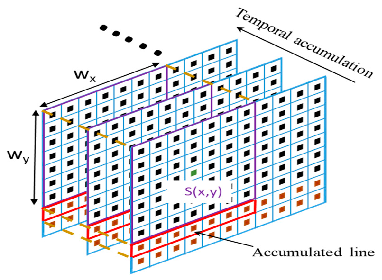
2.4. Spatiotemporal Box Filter
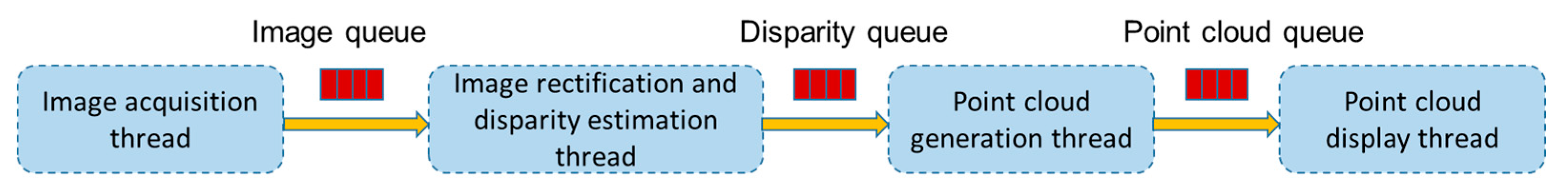
2.5. Real-Time Acquisition and Reconstruction of 3D Face
3. Results
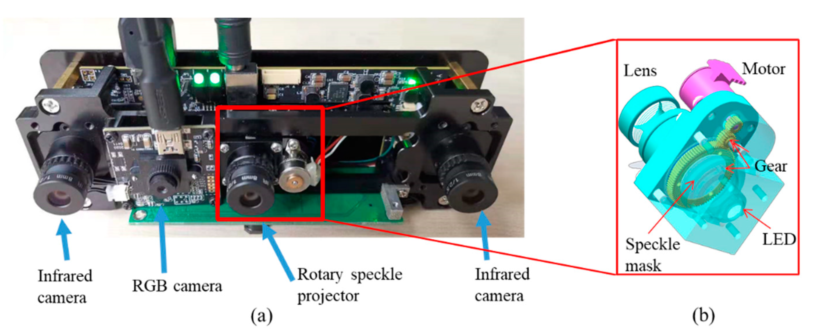
3.1. Setup
3.2. Evaluation on 3D Reconstruction Precision and Performance
- (1)
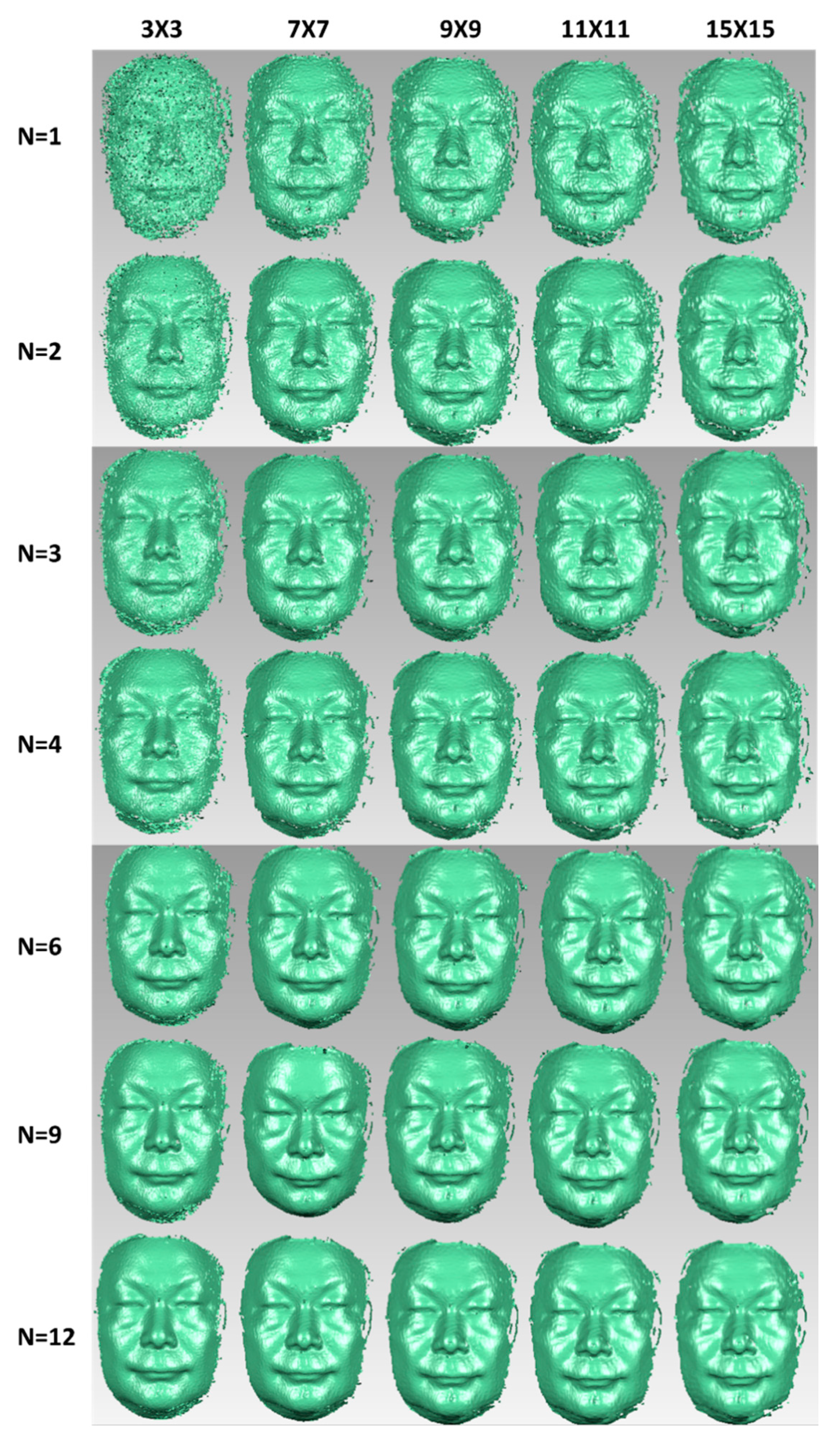
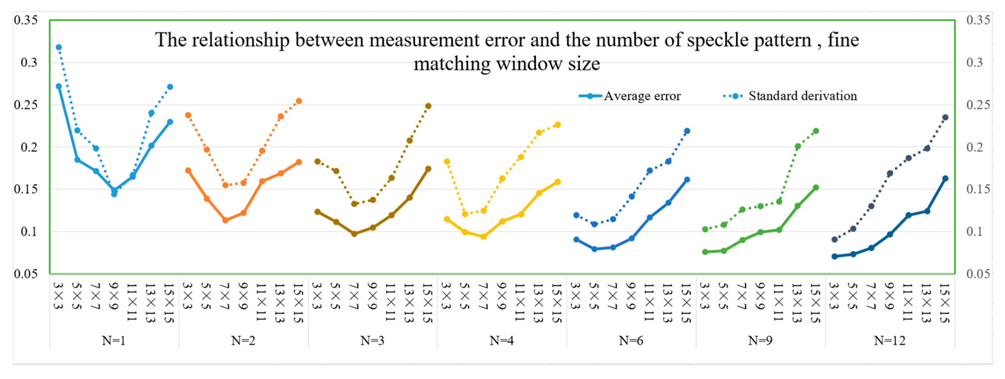
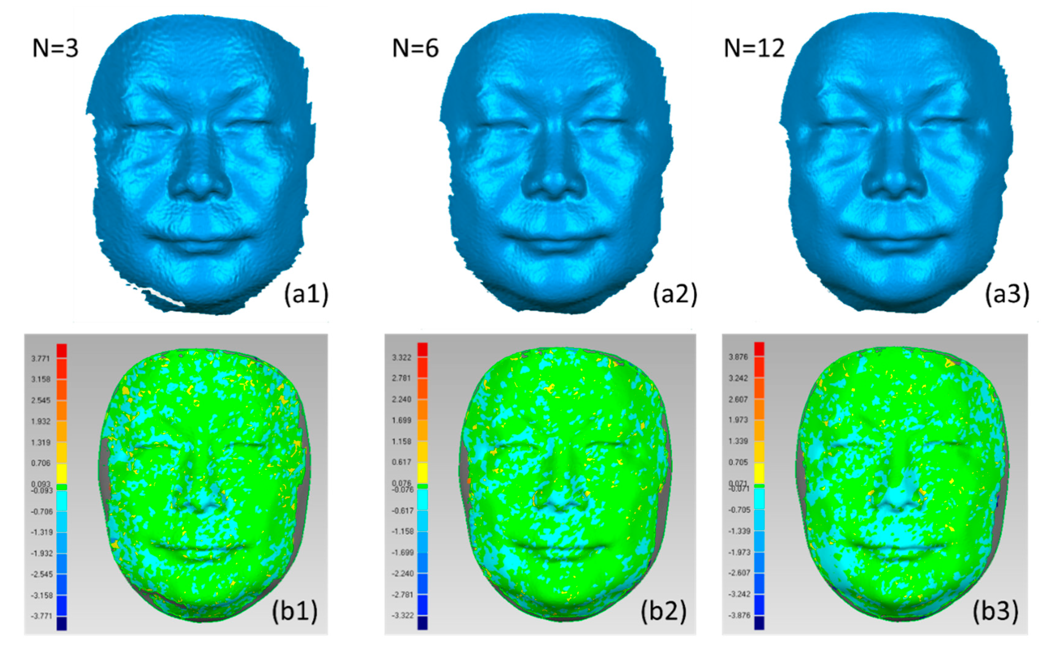
- In the current configuration environment, the reconstruction accuracy of the 3D model continues to improve as N increases the number of speckle stereo image pairs, but when the projected speckle patterns exceed a certain range (N ≥ 6), the trend of accuracy improvement gradually weakens.
- (2)
- To obtain a higher 3D reconstruction accuracy, the optimal fine matching window is not as small as possible. For a given number of patterns, the optimal fine window size is determined for a given number of patterns. For example, when N = 1, 9 × 9 is the optimal fine window size and the measurement error is the smallest; when N = 3, the optimal fine window size is 7 × 7. When N = 12, the optimal fine window size becomes 3 × 3, the average error is 0.071 mm, and the standard deviation is 0.091 mm. From the overall trend, as the number of speckle stereo image pairs increase, the optimal matching window continues to shrink.
- (3)
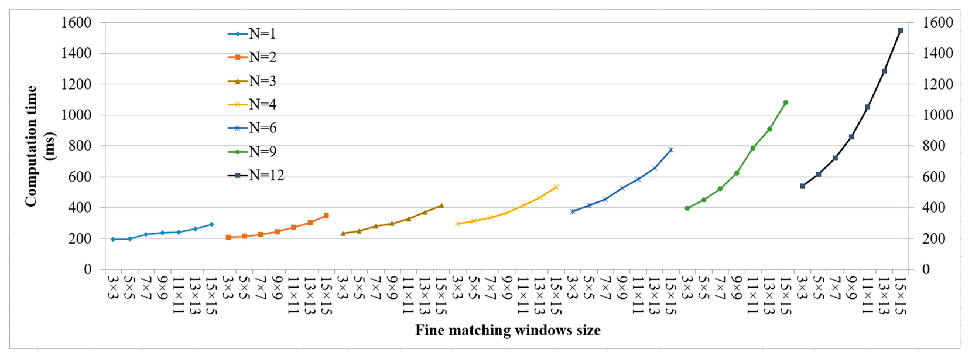
- The computation time increases as the matching window increases. The greater the number of projected patterns involved in the calculation, the faster the computation time. As shown in Figure 10, in the case of a fixed number of speckle patterns, the computation time increases proportionally with the increase in the matching window.
- (4)
- There is a trade-off between measurement accuracy and calculation cost. When the control average error is less than 0.15 mm, the overall reconstruction error decreases with the increase in the number of projection patterns, and the optimal window size continues to shrink. Combining the comprehensive analysis of Figure 9 and Figure 10, it is found that to obtain the best measurement accuracy for each number, N, of stereo image pairs, the computation time also increases slightly as the number of speckle patterns increases.
3.3. Real-Time Improvement for Three Speckle Patterns Projection
4. Discussion
- (1)
- Measurement accuracy. The STBF-accelerated spatiotemporal correlation matching strategy proposed in this paper differs from the test results in the literature [23]. First, the literature [23] did not consider the human face as the analysis object and did not use a coarse-to-fine matching strategy, and its calculation speed was not as good as the method in this paper. Furthermore, based on the comparison of the calculation results, it was found that the combination trend between the selected matching window size and the number of speckle patterns was different. In [23], when the number of projected speckle patterns exceeded three frames, the change in the size of the matching window had only a small effect on the reconstruction accuracy. The test results in this study show that, as the number of projection patterns increases, the 3D reconstruction accuracy continues to improve. When the number of patterns is greater than six, the trend of accuracy improvement gradually slows down. This phenomenon may be caused by differences in the measurement object.
- (2)
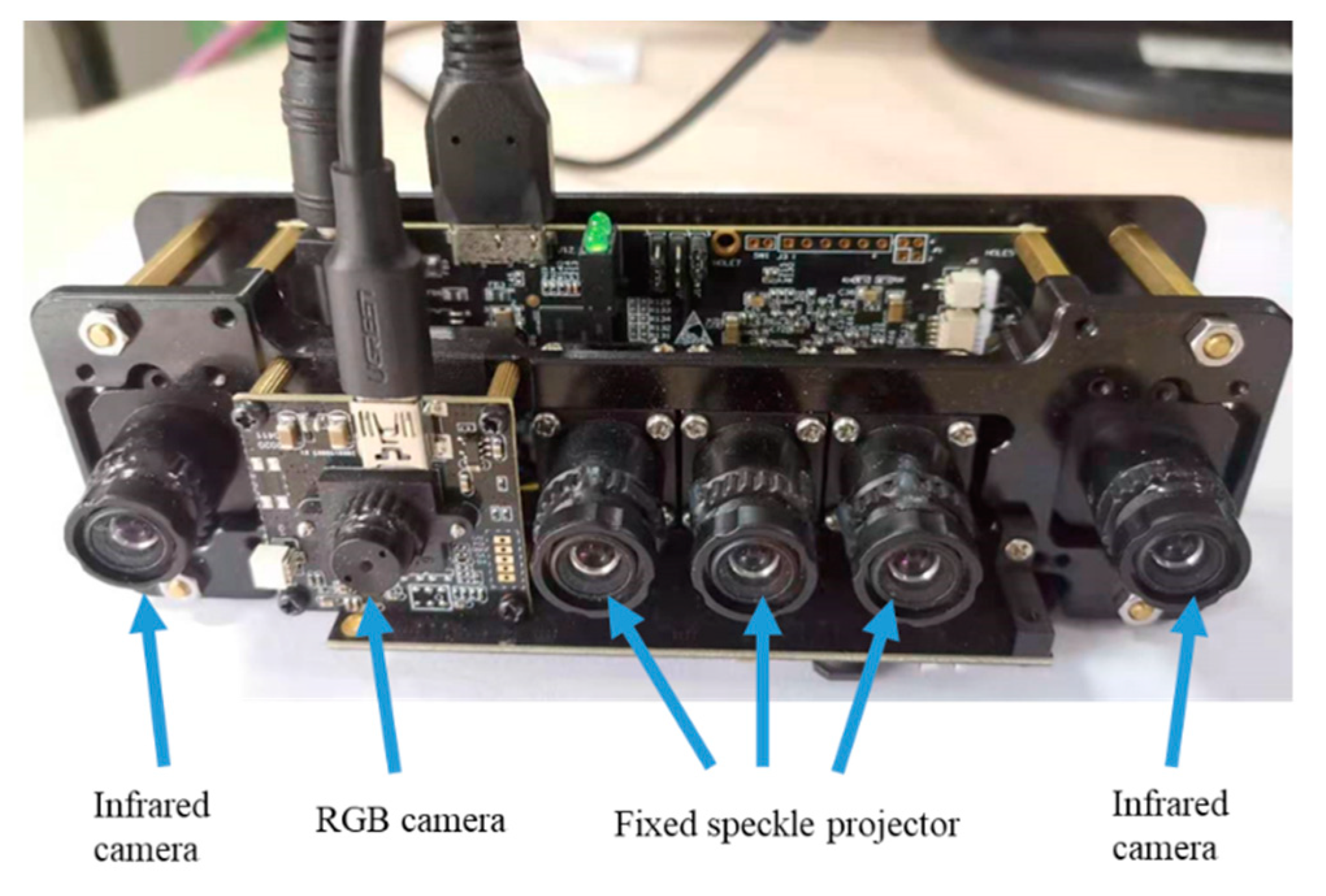
- Balance of measurement accuracy and time cost. A 3D face acquisition device with a rotating speckle projector is more suitable for use in scenes where the accuracy requirements are strict, and there is no clear limitation on the acquisition time. To obtain better reconstruction accuracy, more stereo image pairs were selected to participate in the spatiotemporal stereo-matching process, which is more suitable for scenes where objects remain stationary. According to the research results of this study, six sets of image pairs met the requirements for high-precision modelling. When reconstructing fast-moving objects, the authors attempted to reduce the number of stereo image pairs and employed 3D reconstruction equipment with fixed speckle projectors for 3D face image acquisition.
- (3)
- Real-time acquisition, reconstruction and display. Using the single-shot speckle structure [17,18,19], the acquisition time of the stereo image pair was short, but the real-time reconstruction effect was usually not achieved. Although the literature [27] achieved a real-time reconstruction frequency of 30 fps, the accuracy was only 0.55 mm, which is far from the accuracy of the proposed method. Aiming at 3D face acquisition equipment using a fixed speckle projector, the method in this study implements real-time image acquisition and real-time 3D face reconstruction. However, during the 3D data display process, the point-cloud structure can be used to display 3D data in real time through the openGL interface. If the triangular facet structure of texture mapping is adopted, it is limited by openGL’s utilisation of the low-level image cache and does not display 3D data in real time. In our next step, the authors will study the openGL parallel display strategy, which has achieved a more realistic display effect of 3D data.
5. Conclusions
Author Contributions
Funding
Institutional Review Board Statement
Informed Consent Statement
Data Availability Statement
Acknowledgments
Conflicts of Interest
References
- Khan, D.; Shirazi, M.A.; Kim, M.Y. Single-shot laser speckle-based 3D acquisition system for medical applications. Opt. Lasers Eng. 2018, 105, 43–53. [Google Scholar] [CrossRef]
- Gilani, S.Z.; Mian, A. Learning from millions of 3D scans for large-scale 3D face recognition. In Proceedings of the 31st IEEE/CVF Conference on Computer Vision and Pattern Recognition, Salt Lake City, UT, USA, 18–23 June 2018; p. 1896. [Google Scholar]
- Hassner, T. Viewing real-world faces in 3D. In Proceedings of the 2013 IEEE International Conference on Computer Vision, Sydney, Australia, 1–8 December 2013; p. 3607. [Google Scholar]
- Sturm, J.; Bylow, E.; Kahl, F.; Cremers, D. CopyMe3D: Scanning and Printing Persons in 3D. Pattern Recogn. 2013, 8142, 405–414. [Google Scholar]
- Fyffe, G.; Nagano, K.; Huynh, L.; Saito, S.; Busch, J.; Jones, A.; Debevec, P. Multi-view stereo on consistent face topology. Comput. Graph. Forum 2017, 36, 295–309. [Google Scholar] [CrossRef]
- Zhang, S. High-speed 3D shape measurement with structured light methods: A review. Opt. Lasers Eng. 2018, 106, 119–131. [Google Scholar] [CrossRef]
- Cester, L.; Lyons, A.; Braidotti, M.; Faccio, D. Time-of-Flight imaging at 10-ps resolution with an ICCD camera. Sensors 2019, 19, 180. [Google Scholar] [CrossRef] [PubMed] [Green Version]
- Booth, J.; Roussos, A.; Ponniah, A.; Dunaway, D.; Zafeiriou, S. Large scale 3D morphable models. Int. J. Comput. Vis. 2018, 126, 233–254. [Google Scholar] [CrossRef] [PubMed] [Green Version]
- Bouaziz, S.; Wang, Y.G.; Pauly, M. Online modelling for real-time facial animation. ACM Trans. Graph. 2013, 32, 40. [Google Scholar] [CrossRef]
- Garrido, P.; Zollhofer, M.; Casas, D.; Valgaerts, L.; Varanasi, K.; Perez, P.; Theobalt, C. Reconstruction of personalized 3D face rigs from monocular video. ACM Trans. Graph. 2016, 35, 28. [Google Scholar] [CrossRef]
- Jackson, A.S.; Bulat, A.; Argyriou, V.; Tzimiropoulos, G. Large Pose 3D Face Reconstruction from a Single Image via Direct Volumetric CNN Regression. In Proceedings of the 16th IEEE International Conference on Computer Vision, Venice, Italy, 22–29 October 2017; p. 1031. [Google Scholar]
- Feng, Y.; Wu, F.; Shao, X.; Wang, Y.; Zhou, X. Joint 3D face reconstruction and dense alignment with position map regression network. In Proceedings of the 15th European Conference on Computer Vision, Munich, Germany, 8–14 September 2018. [Google Scholar]
- Kwon, H.; Kim, Y.; Yoon, H.; Choi, D. Classification score approach for detecting adversarial example in deep neural network. Multimed. Tools Appl. 2021, 80, 10339–10360. [Google Scholar] [CrossRef]
- Kwon, H.; Lee, J. AdvGuard: Fortifying Deep Neural Networks against Optimized Adversarial Example Attack. IEEE Access 2020. [Google Scholar] [CrossRef]
- Xue, J.; Zhang, Q.; Li, C.; Lang, W.; Wang, M.; Hu, Y. 3D face profilometry based on Galvanometer scanner with infrared fringe projection in high speed. Appl. Sci. 2019, 9, 1458. [Google Scholar] [CrossRef] [Green Version]
- Ito, M.; Ishii, A. A three-level checkerboard pattern (tcp) projection method for curved surface measurement. Pattern Recogn. 1995, 28, 27–40. [Google Scholar] [CrossRef]
- Zuo, C.; Feng, S.; Huang, L.; Tao, T.; Yin, W.; Chen, Q. Phase Shifting Algorithms for Fringe Projection Profilometry: A Review. Opt. Lasers Eng. 2018, 109, 23–59. [Google Scholar] [CrossRef]
- Boyer, K.L.; Kak, A.C. Colour-encoded structured light for rapid active ranging. IEEE Trans. Anal. Mach. Intell. 1987, PAMI-9, 14–28. [Google Scholar] [CrossRef] [PubMed]
- Baek, S.-H.; Kim, M.H. Stereo fusion: Combining refractive and binocular disparity. Comput. Vis. Image Underst. 2016, 146, 52–66. [Google Scholar] [CrossRef]
- Shi, H.; Zhu, H.; Wang, J.; Yu, S.-Y.; Fu, Z.-F. Segment-based adaptive window and multi-feature fusion for stereo matching. J. Algorithm Comput. Technol. 2016, 10, 3–11. [Google Scholar] [CrossRef] [Green Version]
- Liu, Y.; Zhang, Q.; Liu, Y.; Yu, X.; Hou, Y.; Chen, W. High-speed 3D shape measurement using rotary mechanical projector. Opt. Express 2021, 29, 7885. [Google Scholar] [CrossRef]
- Song, Z.; Tang, S.; Gu, F.; Shi, C.; Feng, J. DOE-based structured-light method for accurate 3D sensing. Opt. Lasers Eng. 2019, 120, 21–30. [Google Scholar] [CrossRef]
- Keselman, L.; Woodfill, J.I.; Grunnet-Jepsen, A. Intel® RealSense™ Stereoscopic Depth Cameras. In Proceedings of the 30th IEEE/CVF Conference on Computer Vision and Pattern Recognition Workshops, Honolulu, HI, USA, 21–26 July 2017; p. 1267. [Google Scholar]
- Pathirana, P.N.; Li, S.Y.; Trinh, H.M.; Seneviratne, A. Robust real-time bio-kinematic movement tracking using multiple Kinects for tele-rehabilitation. IEEE Trans. Ind. Electr. 2016, 63, 1822–1833. [Google Scholar] [CrossRef] [Green Version]
- Gu, F.; Song, Z.; Zhao, Z. Single-Shot Structured Light Sensor for 3D Dense and Dynamic Reconstruction. Sensors 2020, 20, 1094. [Google Scholar] [CrossRef] [Green Version]
- Khan, D.; Kim, M.Y. High-density single shot 3D sensing using adaptable speckle projection system with varying pre-processing. Opt. Lasers Eng. 2021, 136, 106312. [Google Scholar] [CrossRef]
- Guo, J.P.; Peng, X.; Li, A.; Liu, X.; Yu, J. Automatic and rapid whole-body 3D shape measurement based on multi-node 3D sensing and speckle projection. Appl. Opt. 2017, 56, 8759–8768. [Google Scholar] [CrossRef]
- Yin, W.; Hu, Y.; Feng, S.; Huang, L.; Kemao, Q.; Chen, Q.; Zuo, C. Single shot 3D shape measurement using an end-to-end stereo-matching network for speckle projection profilometry. Opt. Express 2021, 29, 13388. [Google Scholar] [CrossRef]
- Zhou, P.; Zhu, J.; Jing, H. Optical 3-D surface reconstruction with colour binary speckle pattern encoding. Opt. Express 2018, 26, 3452–3465. [Google Scholar] [CrossRef]
- Ishii, I.; Yamamoto, K.; Doi, K.; Tsuji, T. High-speed 3D image acquisition using coded structured light projection. In Proceedings of the International Conference on Intelligent Robots and Systems, San Diego, CA, USA, 29 October 2007; p. 925. [Google Scholar]
- Große, M.; Kowarschik, R. Space-Time Multiplexing in a Stereo Photogrammetry Setup; Osten, W., Kujawinska, M., Eds.; Springer: Berlin/Heidelberg, Germany, 2009; pp. 755–759. [Google Scholar]
- Harendt, B.; Grosse, M.; Schaffer, M.; Kowarschik, R. 3D shape measurement of static and moving objects with adaptive spatiotemporal correlation. Appl. Opt. 2014, 53, 7507–7515. [Google Scholar] [CrossRef]
- Tang, Q.J.; Liu, C.; Cai, Z.W.; Zhao, H.W.; Liu, X.L.; Peng, X. An improved spatiotemporal correlation method for high-accuracy random speckle 3D reconstruction. Opt. Lasers Eng. 2018, 110, 54–62. [Google Scholar] [CrossRef]
- Zhou, P.; Zhu, J.P.; You, Z.S. 3-D face registration solution with speckle encoding based spatial-temporal logical correlation algorithm. Opt. Express 2019, 27, 21004–21019. [Google Scholar] [CrossRef]
- Fu, K.; Xie, Y.; Jing, H. Fast spatial-temporal stereo matching for 3D face reconstruction under speckle pattern projection. Image Vis. Comput. 2019, 85, 36–45. [Google Scholar] [CrossRef]
- Fu, L.; Peng, G.; Song, W. Histogram-based cost aggregation strategy with joint bilateral filtering for stereo matching. Int. J. Comput. Vis. 2016, 10, 173–181. [Google Scholar] [CrossRef]
- Xue, Y.; Cheng, T.; Xu, X.; Gao, Z.; Li, Q.; Liu, X.; Wang, X.; Song, R.; Ju, X.; Zhang, Q. High-accuracy and real-time 3D positioning, tracking system for medical imaging applications based on 3D digital image correlation. Opt. Laser Eng. 2017, 88, 82–90. [Google Scholar] [CrossRef]
- Zhang, Z. A flexible new technique for camera calibration. IEEE Trans. Pattern Anal. Mach. Intell. 2000, 22, 1330–1334. [Google Scholar] [CrossRef] [Green Version]
- Barnes, C.; Shechtman, E.; Finkelstein, A.; Goldman, D.B. PatchMatch: A randomized correspondence algorithm for structural image editing. ACM Trans. Graph. 2009, 28, 24. [Google Scholar] [CrossRef]
- Optical 3-D Measuring Systems—Optical Systems Based on Area Scanning: VDI/VDE 2634 Blatt 2-2012; Beuth Verlag: Berlin, Germany, 2012.


| Pattern Number | Optimal Window (1) (pixel) | Min. Avg. Err (2) (mm) | Min. Std. (3) (mm) | Computation Time on CPU (4) (ms) | Computation Time on GPU (5) (ms) |
|---|---|---|---|---|---|
| N = 1 | 9 × 9 | 0.149 | 0.144 | 218 | 30 |
| N = 3 | 7 × 7 | 0.097 | 0.133 | 280 | 35 |
| N = 6 | 5 × 5 | 0.079 | 0.109 | 338 | 65 |
| N = 9 | 3 × 3 | 0.076 | 0.102 | 390 | 97 |
| N = 12 | 3 × 3 | 0.071 | 0.091 | 554 | 121 |
Publisher’s Note: MDPI stays neutral with regard to jurisdictional claims in published maps and institutional affiliations. |
© 2021 by the authors. Licensee MDPI, Basel, Switzerland. This article is an open access article distributed under the terms and conditions of the Creative Commons Attribution (CC BY) license (https://creativecommons.org/licenses/by/4.0/).
Share and Cite
Xiong, W.; Yang, H.; Zhou, P.; Fu, K.; Zhu, J. Spatiotemporal Correlation-Based Accurate 3D Face Imaging Using Speckle Projection and Real-Time Improvement. Appl. Sci. 2021, 11, 8588. https://doi.org/10.3390/app11188588
Xiong W, Yang H, Zhou P, Fu K, Zhu J. Spatiotemporal Correlation-Based Accurate 3D Face Imaging Using Speckle Projection and Real-Time Improvement. Applied Sciences. 2021; 11(18):8588. https://doi.org/10.3390/app11188588
Chicago/Turabian StyleXiong, Wei, Hongyu Yang, Pei Zhou, Keren Fu, and Jiangping Zhu. 2021. "Spatiotemporal Correlation-Based Accurate 3D Face Imaging Using Speckle Projection and Real-Time Improvement" Applied Sciences 11, no. 18: 8588. https://doi.org/10.3390/app11188588