1. Introduction
A storage vessel that consists of a metallic liner wrapped with a carbon fiber-resin composite to work at high pressure has been widely applied to fuel containers for compressed natural gas (CNG) vehicles. The liner is manufactured by cold D.D.I. (deep drawing and ironing) to obtain the desired diameter and thickness of the cylinder and by hot spinning to form a dome shape. The D.D.I. process shown in
Figure 1 is a continuous process that uses deep drawing to reduce the diameter of the billet and subsequent ironing to reduce the thickness of the workpiece.
To manufacture a CNG pressure vessel with the liner dimensions shown in
Figure 2, a first stage (deep drawing), second stage (redrawing + ironing 1 + ironing 2), and third stage (redrawing + ironing) have been performed [
1,
2]. In the first stage, an initial thick blank is manufactured into a cup shape using a tractrix die without a blank holder to prevent wrinkling. The tractrix die reduces radial stresses and punch loads occurring at the blank wall and increases the formability. In previous studies, wrinkling or buckling in deep drawing of both aluminum and copper sheets was investigated using a tractrix die [
3]. Pernis et al. suggested a rapid determination method for the LDR (limiting drawing ratio) based on the characteristic limit load, which consumes less time, and performed an experimental investigation of an automotive aluminum alloy sheet [
4].
A linear buckling analysis of the pressure vessel was conducted, and the maximum buckling load was estimated [
5]. Kesharwani et al. designed a modified conical tractrix die to reduce the deformation force and to enhance the LDR, and the formability of a tailor friction stir welded sheet blank was improved by 27% [
6]. Kim et al. developed the standard interpretation model of non-linear finite element analysis of an E-glass/epoxy filament wound composite pressure vessel [
7].
Dhaiban et al. proposed a simple process for the deep drawing of elliptical cups without a blank holder. The effects of die and punch geometry according to the half-cone angle and punch fillet radius on the LDR and on the drawing load were investigated for the optimization of the process [
8]. Sener and Kurtaran presented the optimization of process parameters for reducing the risk of failure due to wrinkling and fracture in the deep drawing of a rectangular cup. The blank holder force, friction coefficient, punch radius, and initial blank shape were chosen as design parameters based on wrinkling and fracture criteria [
9].
Fazli and Arezoo proposed an analytical method for estimating the LDR of the redrawing stages in a deep drawing process to predict the limit ratio for redrawing with/without intermediate annealing processes. The presented method was in good agreement with the experimental and numerical result, and the effect of process parameters on the LDR was investigated [
10]. Leu suggested a new equation incorporating the value of the LDR derived as above and the critical drawing load based on the maximum principal load for localization of plastic flow. The maximum drawing load in cup-drawing with a flat-nosed punch was developed [
11].
Faizin et al. conducted an ironing analysis of a deep-drawn aluminum cup. The outer wall thickness was reduced with varying the TRR (thickness reduction ratio) through a die ring with various die angles. Based on this stress, the most optimal condition was selected [
12]. Mukhtar et al. conducted a simulation of an ironing process for a caliber bullet case to determine the minimum forming force on a variety of die angle and thickness reduction rates [
13]. Khodsetan et al. proposed a new ironing method called constrained ironing for producing thin-walled cans and components with uniform thickness [
14].
The second stage of the existing D.D.I. process performs drawing, ironing 1, and ironing 2 separately with three different dies, which has required high manufacturing cost and large installation space. To solve the above problems, this study suggests a second stage using a new combined redrawing-ironing die, as shown in
Figure 3. A theoretical formula to calculate the forming load of the combined redrawing-ironing die was established and verified by comparing it with finite element analysis results. The forming load, maximum thickness reduction ratio in the second stage, and forming defects in the third stage were analyzed by varying the DIR (redrawing-ironing ratio) in the second stage in order to reduce the high manufacturing cost and installation space based on the design rules in the actual field. The new combined redrawing-ironing process was verified by comparing it with the existing process.
2. Design of a Combined and Redrawing-Ironing Process
2.1. Existing D.D.I. Process
The existing D.D.I. process to form the cylinder part of a liner includes drawing to reduce the diameter of the billet and ironing to reduce the thickness of the billet. In the first stage, an initial blank is manufactured into a cup shape using a tractrix die to avoid forming defects without a blank holder. In the second stage, redrawing and two ironing processes (D.I.I.) are continuously conducted, and in the third stage, redrawing and ironing processes (D.I.) are performed to obtain the final thickness and diameter of the liner [
1]. Theoretical design rules of the D.D.I. process are shown in Equations (1)–(12) [
4].
dpi,
ddij, and
diij are diameters of the punch, drawing die, and ironing dies at the ith stage and jth process.
bi,
tij, and
Aij are the draw ratio, thickness of material, and cross sectional area, respectively. Based on the design rules provided by the NK company [
7], the blank diameter (
D0) is 1010 mm, and the initial thickness (
t0) is 12.5 mm. The LDR (
b1 = 1.84) in the first stage and tip clearance (
C1 = 5%,
C2 = 0, and
C3 = −5%) between the drawing die and the workpiece in each stage were found from the actual field.
The reduction ratio of the cross sectional area (RA) in one stage is defined as Equation (12).
is the cross sectional area before forming, and
is the cross sectional area after forming. The limit reduction ratio of the cross sectional area (LRA) in each stage is 50%, which is provided by the actual field. When ironing processes are carried out two times in one stage, each reduction ratio of the cross sectional area (RA
ironing) in Equation (13) should be the same, and the limit reduction ratio of the cross sectional area in the ironing process (LRA
ironing) is not allowed to exceed 35%.
is the cross sectional area before ironing, and
is the cross sectional area after ironing.
2.2. New Combined Redrawing-Ironing Process
The drawing ratio (
bi) in the existing D.D.I. process, which considers diameter reduction, cannot be applied to the new combined redrawing-ironing process. Thus, the redrawing-ironing ratio (
DIR), which considers both diameter reduction and wall thickness reduction, is newly defined in Equation (14), which is the ratio between the workpiece diameter (
D) after the first deep drawing and the punch diameter (
Dp) in the second stage. It was used to design the combined redrawing-ironing process.
2.2.1. Force Analysis
A new theoretical formula to obtain the combined redrawing-ironing load was suggested by adding the drawing load (
Fd) to the ironing load (
Fi), which is the sum of the tensile force acting on the workpiece (
F1) and the load acting on the punch (
F2).
Figure 4 shows stresses in a slab element of a workpiece during an ironing process with force calculated from Equation (15).
By applying the plane strain yielding condition (
Y’), which does not take into account thickness deformation in the radial direction, Equation (15) can be expressed as Equation (16).
where
.
By integration of Equation (16) with the boundary condition of no back tension, the ironing stress in the z-direction (
σz) is rewritten as Equation (17). The sum of the tensile force (
F1) is calculated by multiplying the ironing stress by the cross-sectional area of the product obtained after ironing, as shown in Equation (18).
Df is the diameter of the workpiece of the neutral plane after ironing, and
hf is the workpiece thickness after ironing.
The punch load (
F2) is calculated by adding the force from the pressure of the die to the force from the shear stress, as shown in Equation (19).
It can be assumed that
and
in the actual process [
15], so the ironing load is expressed as Equation (20), where
and
are the diameter on the neutral surface and radius on the neutral surface after ironing, respectively.
where
.
By adopting
, where
is the inside radius of the product after ironing, the ironing load (
Fi) can be rewritten as Equation (20):
The existing drawing load in the second stage is based on an empirical equation with constant thickness, as shown in Equation (22a) [
15], while the new combined redrawing-ironing process has thickness reduction (
ho →
hf), as shown in
Figure 5. The drawing load was modified as shown in Equation (22b). The combined redrawing-ironing load was derived by adding the ironing load (Equation (21) to the drawing load (Equation (22b)), as shown in Equation (23), where
k is the thickness reduction ratio (
).
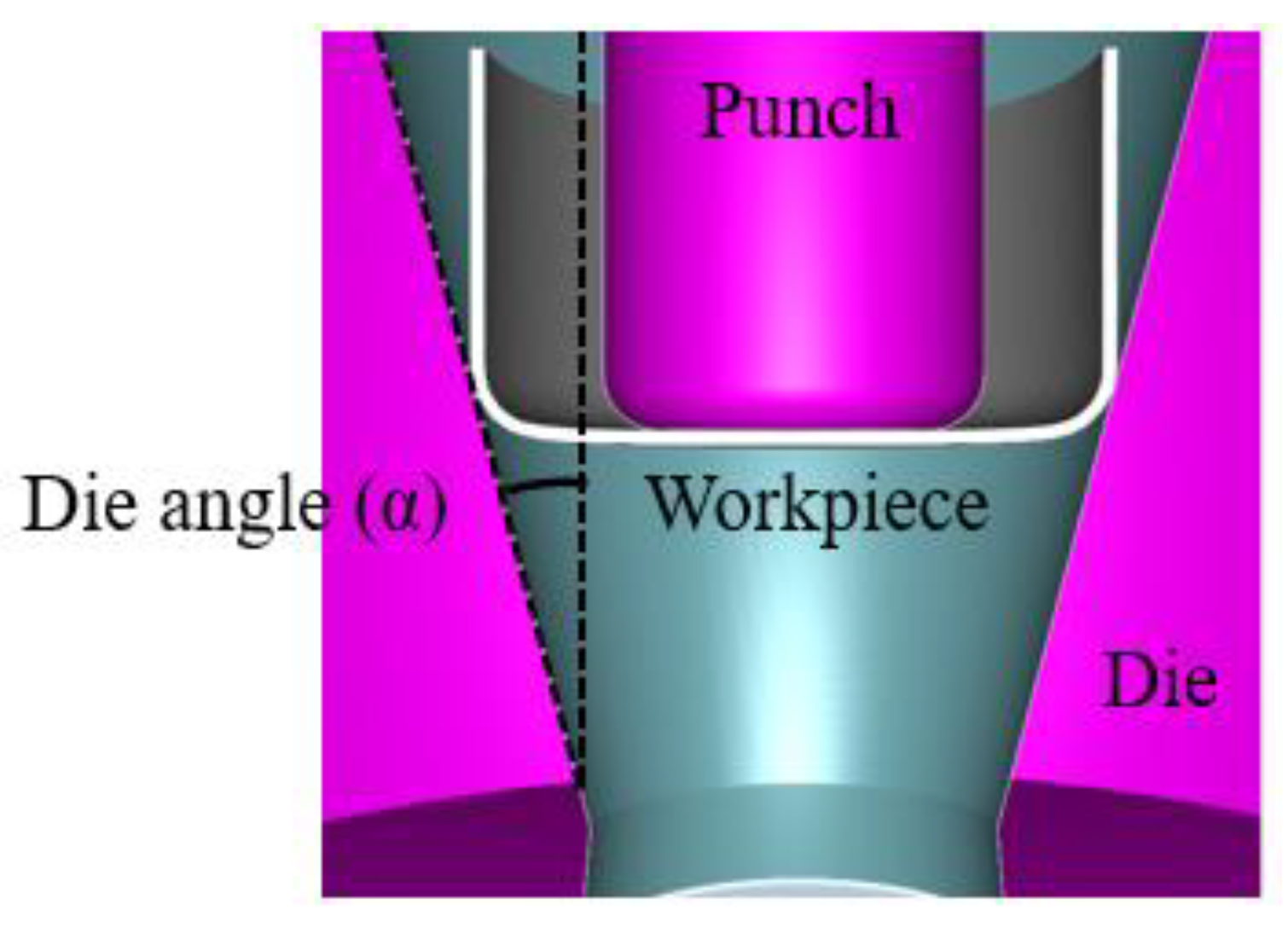
2.2.2. Force According to the Die Angles and DIRs
To determine the optimal die angle (α) between the workpiece and die shown in
Figure 6, combined redrawing-ironing loads with different die angles (1–15°) for DIRs (1.1–1.7) were calculated by using Equation (23). The loads with the thinning workpiece thickness (12.8 mm → 3.2 mm) are plotted in
Figure 7 for a DIR of 1.1. The load increased with the larger die angle at all DIRs, but the amount of increment was reduced gradually. The loads approached about 850 tons at the die angle of 15° for DIRs of 1.1–1.7. In the case of a DIR of 1.1, the loads at the die angles of 14° and 15° are 803.2 tons and 799.2 tons, respectively, which show a small difference of 0.5%. Similar tendencies were observed at DIRs of 1.2–1.7, as shown in
Table 1, so the die angle of 15° was determined to carry out the combined redrawing-ironing process.
3. Finite Element Analysis for Combined Redrawing-Ironing Process
To design the new combined redrawing-ironing process, finite element analysis was conducted using commercial software, Forge Nxt 3.0.
3.1. Analysis Conditions and Material Property
The behavior of the workpiece was set to a deformable domain with a volume mesh, which was periodically remeshed as the process progressed. The die and the punch were assumed as rigid bodies with a surface mesh, which means that their deformation is negligible. The punch velocity of 50 mm/s was suggested in the actual field, and the friction coefficient (
μ) between the workpiece and the die was defined as 0.05 [
16]. The flow stress equation and the material properties were obtained through a tensile test of 34CrMo4, as shown in Equation (24) and
Table 2, respectively [
16].
Forge NxT 2.0 software uses the Hansel–Spittel model shown in Equation (25), which is based on the relation of the variables of strain, strain rate, and temperature. Material constants of the equation (
A,
m1,
m2,
m3,
m4,
m5,
m6,
m7,
m8, and
m9) were obtained from the flow stress-strain data of
Figure 8, as listed in
Table 3.
3.2. Simulation Results
3.2.1. Forming Analysis According to the Die DIRs
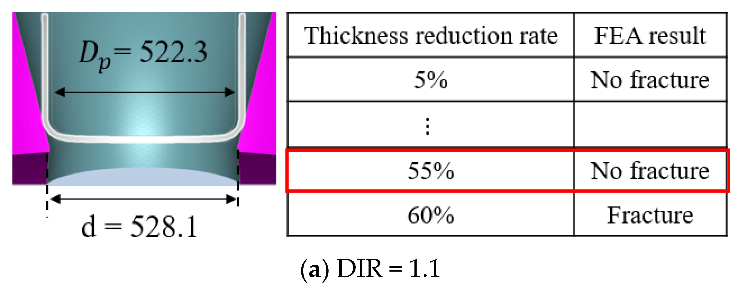
Finite element analyses of the combined redrawing-ironing process in the second stage were conducted at intervals of a 5% wall thickness reduction rate according to the DIRs (1.1–1.7) until a forming defect occurred. The product obtained after finishing the first deep drawing process, which has a wall thickness of 12.8 mm and outer diameter of 574.5 mm, was applied to the workpiece in the second stage. The maximum thickness reduction rate that does not have fracture at each DIR in the second stage is shown in
Figure 9. At a DIR of 1.1, the forming processes according to the thickness reduction rates of 5–60% were carried out just before fracture occurs over 60%.
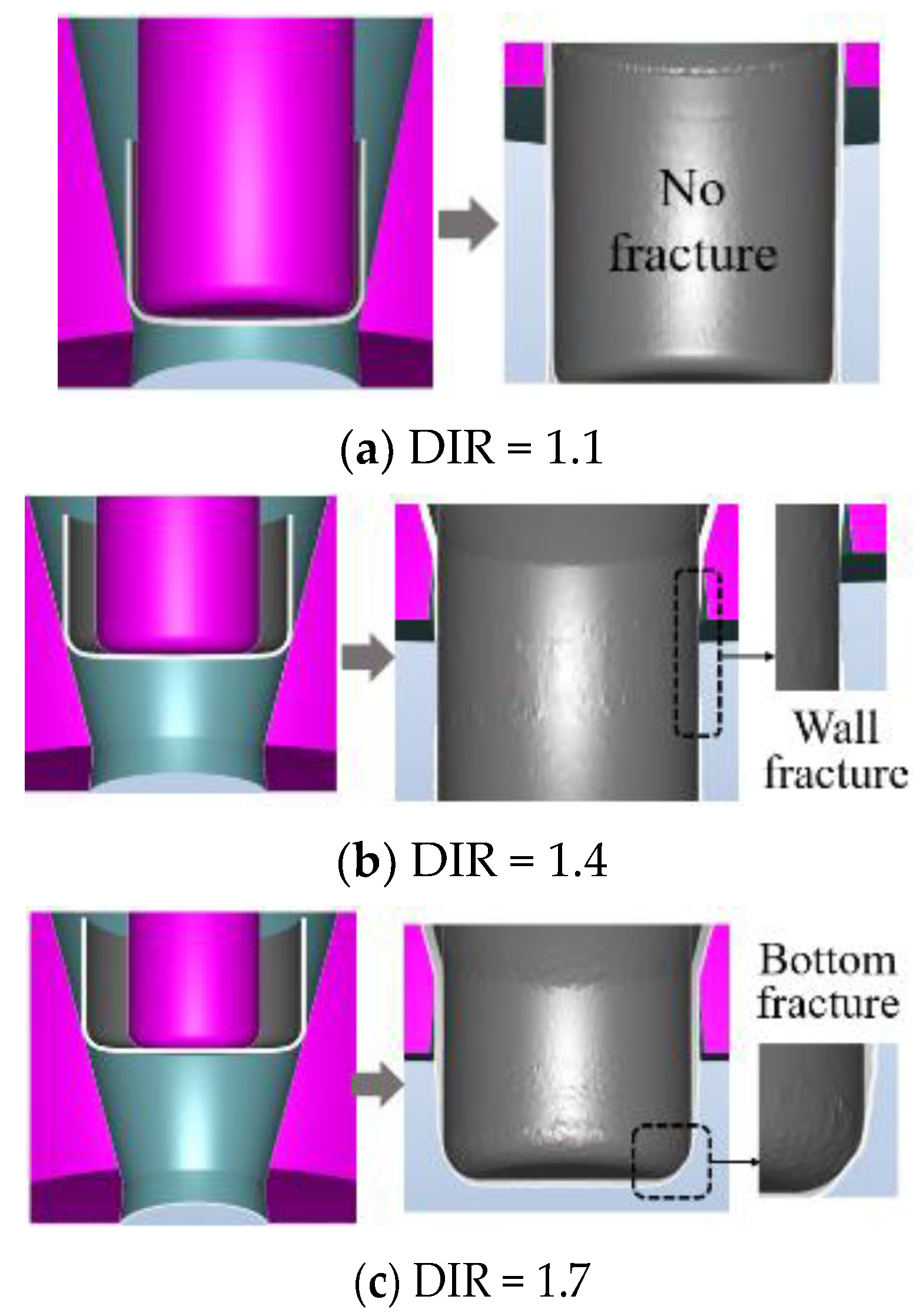
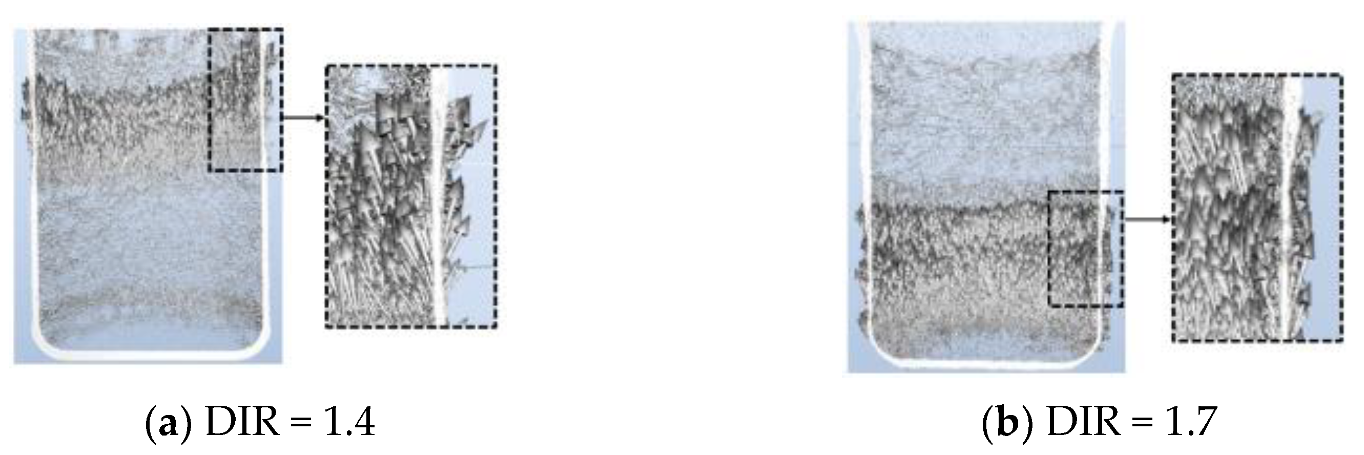
From the fracture tendency according to the DIRs analyzed in
Figure 10, it was found that the increase in the DIR causes more reduction in wall thickness and a sudden change in the cross sectional area to form defects. In cases of DIRs of 1.4 and 1.7, fractures were observed at the middle wall and at the punch corner, respectively. The principal stress in the axial-direction caused the forming defects shown in
Figure 11.
Figure 12 shows the theoretical combined redrawing-ironing (gray), drawing (yellow green), and ironing loads (green) according to the DIRs, and the maximum load (846 tons) was observed at the DIR of 1.4. As the DIR increases, the ironing load tends to decrease, while the drawing load increases.
3.2.2. Optimal DIR Having Maximum Thickness Reduction Rate in the Second Stage
The larger DIR decreased the maximum thickness reduction rate in the second stage and increased the die size, and forming takes more time in the combined redrawing-ironing process. At the DIR of 1.7, the processing time was 15 s more than at the DIR of 1.1, as shown in
Figure 13. When the DIR is too small, both the forming load and thickness reduction rate are high and cause a thinner wall, so fracture occurred in the third stage. Therefore, it is necessary to determine the appropriate DIR to have the maximum thickness reduction rate in the second stage and not to allow fracture in the third stage.
Table 4 shows the maximum thickness reduction rates in the second stage according to the DIRs and formability in the third stage (ironing) to obtain the target thickness of the liner (4.7 mm). When DIRs were 1.1–1.4, tearing occurred in the third stage due to the excessive maximum thickness reduction rate (55–40%), but when DIRs were 1.5–1.7, forming defects were not observed due to the lower thickness reduction rate (35–10%). Considering both the formability in the third stage and the maximum thickness reduction in the second stage, the maximum thickness reduction rate of 35% was determined at the DIR = 1.5 (die diameters (
dd2): 399.7 mm, punch diameter (
dp2): 383.0 mm).
3.2.3. Discussion of Combined Redrawing-Ironing Process
To verify the theoretical formula to calculate the combined redrawing-ironing load,
Figure 14 compares the theoretical loads with those obtained from FEA. The loads were almost 923–929 tons at DIRs from 1.1 to 1.4, while they decreased over the DIR of 1.5. The errors between the FEA and theory decreased when the DIR was higher and were in good agreement in cases of DIRs over 1.6, as shown
Table 5. At the lower DIR, which causes a sudden change in thickness, the theoretical load assuming constant thickness and
in Equation (16) shows relatively large error.
The results of the new redrawing-ironing combined process were compared with those of the second conventional stage and are shown in
Table 6.
Figure 15 shows schemes of the new D.D.I. process with a combined redrawing-ironing die and conventional D.D.I. process. By substituting the three existing dies with one combined redrawing-ironing die, the total die height was reduced by 46.9% (800 mm (400 mm + 200 mm + 200 mm) → 425 mm). The punch diameter was also reduced by 2.8% (394.1 mm → 383.0 mm) because the DIR in the second stage was increased to 1.5 (higher than the existing draw ratio, 1.35). Compared to the conventional D.D.I. process, the ironing rate increased from 33.4% (12.8 mm → 8.52 mm) to 35.0% (12.8 mm → 8.32 mm) in the second stage, and the processing time calculated from the punch velocity (15 mm/s), die heights, and die distances decreased by 49.7% (39.8 s → 20 s). This will contribute to a reduction in manufacturing cost and improvement in productivity.
After carrying out the new and conventional process, based on the results of the punch and die diameters, the reduction rates of cross sectional areas (RA) of the final product are compared in
Table 7. The reduction ratio (54%) of the cross sectional area by the D.D.I. process in the second stage, which exceeds the limit reduction ratio of cross that is carried out in the conventional second stage, exceeds the limit reduction ratio of the cross sectional area, 50%, by improving the phosphate coating and heat treatment condition at the third stage in the actual field, which is carried out carefully on that account. However, the thickness after using the new second stage was reduced from 8.52 mm to 8.32 mm by using the redrawing-ironing die, so the reduction rate of the cross sectional area was decreased from 54% to 51% in the third stage, which can be performed more reliably than the conventional D.D.I. process.
4. Conclusions
In order to improve the second stage of the existing D.D.I. process to manufacture a CNG pressure vessel, this study has suggested a new combined redrawing-ironing process with one die, a theoretical load formula, and a DIR (redrawing-ironing ratio). The summary is as follows.
1. A theoretical load formula for the new combined redrawing-ironing was suggested by adding the drawing load to the ironing load and considering thickness variation. The load errors between the FEA and theory decreased when the DIR was higher and were in good agreement in cases of DIRs over 1.6.
2. By substituting the three existing dies (D.D.I. process) with one combined die (combined redrawing-ironing process), the total die height was reduced by 46.9%; the punch diameter was reduced by 2.8%; the ironing rate was increased from 33.4% to 35.0%; and the processing time was decreased by 49.7%, which altogether contribute to the reduction in manufacturing cost and improvement of productivity.
3. Based on the FEA results, the increase in the DIR causes both a reduction in wall thickness and a sudden change in the cross sectional area to form defects.
4. Considering both the formability in the third stage and the maximum thickness reduction in the second stage, the maximum thickness reduction rate of 35% was determined at the DIR = 1.5 (die diameters (dd2): 399.7 mm, punch diameter (dp2): 383.0 mm).
By adopting the new combined redrawing-ironing process suggested in this study in the actual D.D.I. process, it is considered that it will contribute to the reduction in manufacturing cost by 50%, improvement in the area sectional, and improvement in productivity.
Author Contributions
Conceptualization, G.P. and R.P.; methodology, G.P.; validation, G.P. and H.K.; formal analysis, G.P. and R.P.; investigation, G.P. and H.K.; writing—review and editing, G.P. and C.K.; supervision, C.K.; All authors have read and agreed to the published version of the manuscript.
Funding
This work was supported by the National Research Foundation of Korea (NRF) grant funded by the Korea government (MSIT) (No. 2019R1F1A1058521).
Institutional Review Board Statement
Not applicable.
Informed Consent Statement
Not applicable.
Data Availability Statement
Not applicable.
Acknowledgments
The authors would like to express gratitude to the National Research Foundation of Korea (NRF) for the funding.
Conflicts of Interest
The authors declare no conflict of interest.
References
- Kwak, H.; Park, G.; Seong, H.; Kim, C. Integrated Design of D.D.I., Filament Winding and Curing Processes for Manufacturing the High Pressure Vessel (Type II). Chin. J. Mech. Eng. 2019, 32, 83. [Google Scholar] [CrossRef] [Green Version]
- Sedighi, M.; Rasti, M. An investigation on manufacturing process parameters of CNG pressure vessels. Int. J. Adv. Manuf. Technol. 2007, 38, 958–964. [Google Scholar] [CrossRef]
- Narayanasamy, R.; Sowerby, R. Wrinkling behaviour of cold-rolled sheet metals when drawing through a tractrix die. J. Mater. Process. Technol. 1995, 49, 199–211. [Google Scholar] [CrossRef]
- Pernis, R.; Bareni, I.; Kasala, J.; Lickova, M. Evaluation of limiting drawing ratio(LDR) in deep drawing process. Acta Metall. Slovaca 2015, 21, 258–268. [Google Scholar] [CrossRef] [Green Version]
- Karthik, N.; Reddy, M.J.; NagaKiran, M. Design Optimization and Buckling Analysis of Pressure Vessel. Int. J. Comput. Eng. Res. Trends 2016, 3, 246–250. [Google Scholar]
- Kesharwani, R.K.; Panda, S.K.; Pal, S.K. Experimental investigations on formability of aluminum tailor friction stir welded blanks in deep drawing process. J. Mater. Eng. Perform. 2014, 24, 1038–1049. [Google Scholar] [CrossRef]
- Kim, C.H.; Park, J.H.; Kim, C.; Choi, J.C. Expert system for process planning of pressure vessel fabrication by deep draw-ing and ironing. J. Mater. Process. Technol. 2004, 155, 1465–1473. [Google Scholar] [CrossRef]
- Dhaiban, A.A.; Soliman, M.-E.S.; El-Sebaie, M. Development of deep drawing without blank-holder for producing elliptic brass cups through conical dies. JES J. Eng. Sci. 2013, 41, 1530–1548. [Google Scholar] [CrossRef]
- Sener, B.; Kurtaran, H. Optimization of process parameters for rectangular cup deep drawing by the Taguchi method and genetic algorithm. Mater. Test. 2016, 58, 238–245. [Google Scholar] [CrossRef]
- Fazli, A.; Arezoo, B. An Analytical Method for Prediction of Limiting Drawing Ratio For Redrawing Stages of Axisymmetric Deep Drawn Components. J. Manuf. Sci. Eng. 2014, 136, 021012. [Google Scholar] [CrossRef]
- Leu, D.K. Prediction of the limiting drawing ratio and the maximum drawing load in cup-drawing. Int. J. Mach. Tools Manuf. 1997, 37, 201–213. [Google Scholar] [CrossRef]
- Faizin, A.; Wahjudi, A.; Batan, I.M.L.; Pramono, A.S. Ironing force modeling analysis on aluminum cup using CATIA V5. In AIP Conference Proceedings; AIP Publishing LLC: Melville, NY, USA, 2018; Volume 1983, p. 040013. [Google Scholar]
- Mukhtar, M.N.A.; Batan, I.M.L.; Pramujati, B.; Pramono, A.S. Simulation of Ironing Process for Bullet Case to Get Minimum Forming Force with Variation of Die Angle and Reduction Wall Thickness. Appl. Mech. Mater. 2016, 836, 197–202. [Google Scholar] [CrossRef]
- Khodsetan, M.; Faraji, G.; Abrinia, K. A Novel Ironing Process with Extra High Thickness Reduction: Constrained Ironing. Mater. Manuf. Process. 2015, 30, 1324–1328. [Google Scholar] [CrossRef]
- Kim, N.S.; Kim, H.J. Metal Forming and Analysis; Munundang Publishing: Seoul, Korea, 2002; p. 280. [Google Scholar]
- Bae, J.-H.; Lee, H.-W.; Kim, C. A study on integrated design for manufacturing processes of a compressed natural gas composite vessel. Int. J. Precis. Eng. Manuf. 2014, 15, 1311–1321. [Google Scholar] [CrossRef]
Figure 1.
Scheme of the existing D.D.I. process for manufacturing CNG pressure vessel.
Figure 1.
Scheme of the existing D.D.I. process for manufacturing CNG pressure vessel.
Figure 2.
Dimensions of the liner for the type II CNG vessel.
Figure 2.
Dimensions of the liner for the type II CNG vessel.
Figure 3.
Comparison of the new combined redrawing-ironing process in 2nd stage with conventional one.
Figure 3.
Comparison of the new combined redrawing-ironing process in 2nd stage with conventional one.
Figure 4.
Stresses in a slab element during ironing process.
Figure 4.
Stresses in a slab element during ironing process.
Figure 5.
Thickness variation of the combined redrawing-ironing process in the 2nd stage.
Figure 5.
Thickness variation of the combined redrawing-ironing process in the 2nd stage.
Figure 6.
Die angle (α) between material and die.
Figure 6.
Die angle (α) between material and die.
Figure 7.
Combined redrawing-ironing load according to the die angle (1–15°) at each DIR (1.1).
Figure 7.
Combined redrawing-ironing load according to the die angle (1–15°) at each DIR (1.1).
Figure 8.
Comparison of the flow stress equation curve with the Hansel–Spittel equation.
Figure 8.
Comparison of the flow stress equation curve with the Hansel–Spittel equation.
Figure 9.
Maximum thickness reduction ratio at each DIR in the 2nd stage.
Figure 9.
Maximum thickness reduction ratio at each DIR in the 2nd stage.
Figure 10.
Fracture tendency according to the DIRs.
Figure 10.
Fracture tendency according to the DIRs.
Figure 11.
Principal stress in the axial direction.
Figure 11.
Principal stress in the axial direction.
Figure 12.
Theoretical combined redrawing-ironing load by varying DIRs.
Figure 12.
Theoretical combined redrawing-ironing load by varying DIRs.
Figure 13.
Forming time and load of the combined redrawing-ironing process.
Figure 13.
Forming time and load of the combined redrawing-ironing process.
Figure 14.
Comparison of the combined redrawing-ironing load obtained from FEA and that of theoretical formula by varying DIR.
Figure 14.
Comparison of the combined redrawing-ironing load obtained from FEA and that of theoretical formula by varying DIR.
Figure 15.
Comparison of two processes in the 2nd stage.
Figure 15.
Comparison of two processes in the 2nd stage.
Table 1.
Gaps of the combined redrawing-ironing loads by varying DIR.
Table 1.
Gaps of the combined redrawing-ironing loads by varying DIR.
| Case | Gap of Loads (%) |
|---|
| | Between 13° and 14° | Between 14° and 15° |
|---|
| DIR 1.1 | 0.61 | 0.50 |
| DIR 1.2 | 0.54 | 0.47 |
| DIR 1.3 | 0.48 | 0.42 |
| DIR 1.4 | 0.43 | 0.38 |
| DIR 1.5 | 0.39 | 0.34 |
| DIR 1.6 | 0.39 | 0.31 |
| DIR 1.7 | 0.33 | 0.29 |
Table 2.
Material properties of steel liner (34CrMo4).
Table 2.
Material properties of steel liner (34CrMo4).
| Young’ modulus | 205 GPa |
| Yield strength | 303 MPa |
| Tensile strength | 516 MPa |
| Poisson’s ratio | 0.28 |
Table 3.
Coefficient of Hansel–Spittel equation for 34CrMo4.
Table 3.
Coefficient of Hansel–Spittel equation for 34CrMo4.
Table 4.
Formability of 3rd stage according to the DIRs.
Table 4.
Formability of 3rd stage according to the DIRs.
| Case | Maximum Thickness
Reduction Rate in 2nd Stage | Formability of 3rd Stage |
|---|
| DIR 1.1 | 55% | Tearing |
| DIR 1.2 | 50% | Tearing |
| DIR 1.3 | 45% | Tearing |
| DIR 1.4 | 40% | Tearing |
| DIR 1.5 | 35% | No defect |
| DIR 1.6 | 20% | No defect |
| DIR 1.7 | 10% | No defect |
Table 5.
Error between combined loads obtained from FEA and theoretical formula according to DIR.
Table 5.
Error between combined loads obtained from FEA and theoretical formula according to DIR.
| DIR | 1.1 | 1.2 | 1.3 | 1.4 | 1.5 | 1.6 | 1.7 |
| Error (%) | 14.4 | 12.1 | 10.5 | 8.9 | 5.7 | 1.1 | 0.9 |
Table 6.
Comparison of the new combined redrawing-ironing process with conventional 2nd stage.
Table 6.
Comparison of the new combined redrawing-ironing process with conventional 2nd stage.
| | 2nd Conventional Stage | New Combined Redrawing-
Ironing Process |
|---|
| Number of die | 3 | 1 |
| Die height (mm) | 800 | 425 (46.9% ↓) |
| Punch diameter (mm) | 394.1 | 383 (2.8% ↓) |
| Ironing rate (%) | 33.4% | 35% |
| Process time (s) | 39.8 | 20.0 (49.7% ↓) |
Table 7.
Calculation of reduction rate of cross sectional area (RA) in the 3rd stage.
Table 7.
Calculation of reduction rate of cross sectional area (RA) in the 3rd stage.
| | Conventional D.D.I. | New D.D.I. |
|---|
| 2nd stage | dp = 394.1 mm
di23 = 414.14 mm
A2 = 10,777 mm2 | dp = 383.03 mm
di = 399.67 mm
A2 = 10,229 mm2 |
| 3rd stage | dp = 332.5 mm
di = 341.9 mm
A3 = 4979 mm2
RA = 54% | dp = 332.5 mm
di = 341.9 mm
A3 = 4979 mm2
RA = 51% |
| Publisher’s Note: MDPI stays neutral with regard to jurisdictional claims in published maps and institutional affiliations. |
© 2021 by the authors. Licensee MDPI, Basel, Switzerland. This article is an open access article distributed under the terms and conditions of the Creative Commons Attribution (CC BY) license (https://creativecommons.org/licenses/by/4.0/).


