
Review of Image-Based 3D Reconstruction of Building for Automated Construction Progress Monitoring


Abstract
:1. Introduction
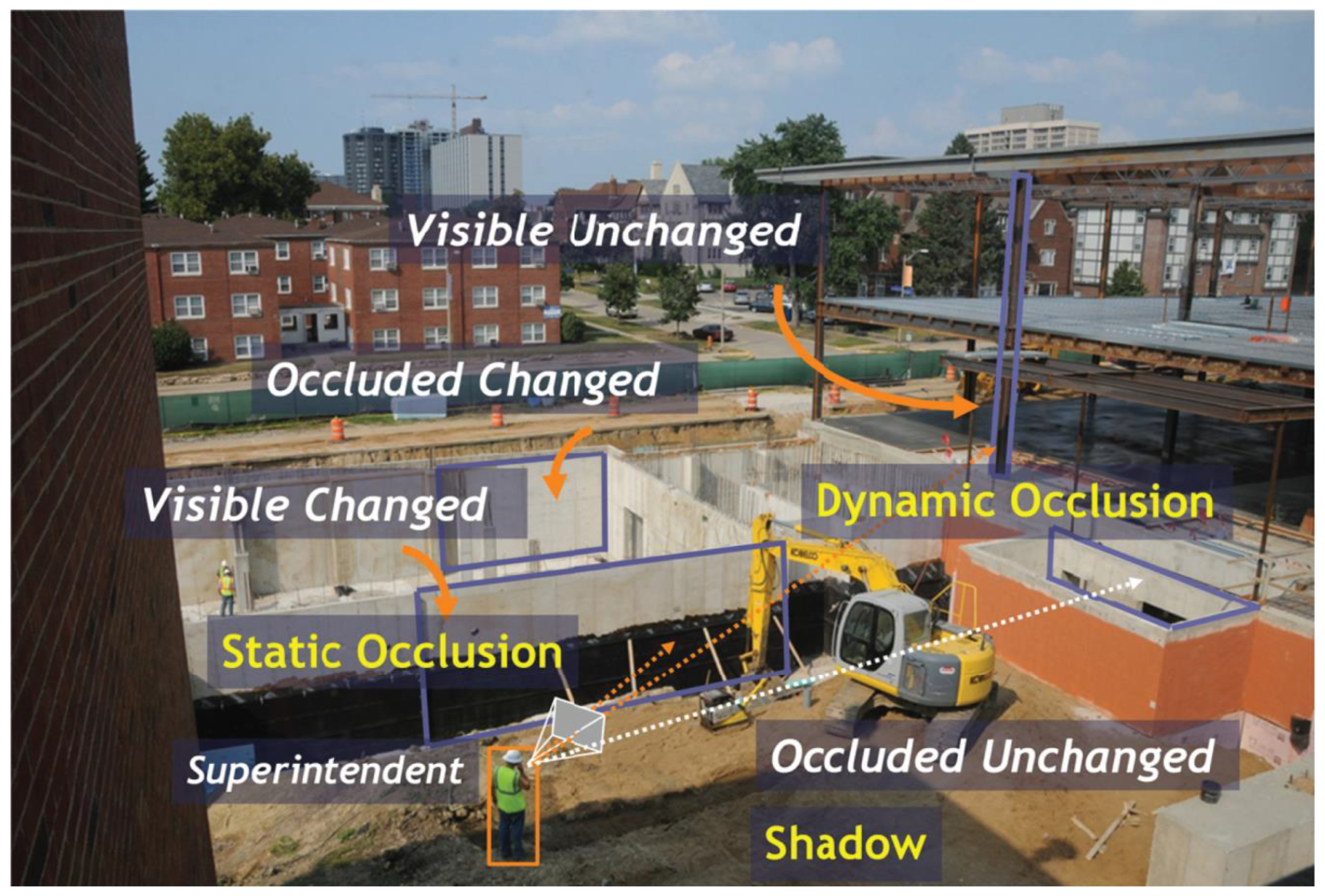
- Although here are many ways to collect images including monocular cameras, binocular cameras, and multi-cameras, the challenges are similar. The intensity of light and shadows seriously affect image quality, and there are many dynamic and static occlusions in addition to self-occlusion at the construction site that prevent researchers from directly observing the building. These factors have brought huge obstacles to 3D reconstruction from images.
- To generate point cloud from images, the feature points in different images need to be found first. Many algorithms have been studied, such as Scale-Invariant Feature Transform (SITF) [13] and Speeded-Up Robust Features (SURF) [14]. Then, these feature points need to be matched with each other to estimate the fundamental matrixes using algorithms such as Random Sample Consensus (RANSAC) [15]. When the images are taken by a moving camera, it is required to reconstruct the point clouds using Structure from Motion (SfM) [16].
- There are various registrations in the process of 3D reconstruction of building, such as 2D–3D and/or 3D–3D registration among images, point clouds, and BIM models.
- The point cloud generated from images is massy and complicated, which contains background, noise, obstacle, etc. Removing the redundant point cloud and keeping only the Region of Interest (RoI) are beneficial for simplifying data processing and improving calculational efficiency.
- The point cloud usually only contains 3D coordinate information. To obtain a semantically rich model to infer progress, it is required to identify the type and state of building components represented by each point from the color and texture in RGB images, which is called semantic recognition/labeling of point clouds.
- Process reasoning is the last step including geometry-based, appearance-based, and relationship-based reasoning.
2. Methodology
- Literature search and screening: This study searched the relevant research results since 2008 from Google Scholar, and the key words included image, photography, video, depth image, computer vision, three-dimensional reconstruction, construction progress monitoring, construction progress tracking, etc. Then, articles related to this topic were selected, and the papers indexed by Web of Science were focused on. Finally, a total of 66 articles were selected, as shown in Table 1.
- Method classification: The knowledge and methods used in these papers are divided and classified into these six aspects: knowledge representation, image collection, and 3D point cloud generation, image-to-BIM alignment, point cloud segmentation, point cloud semantic recognition, and progress reasoning.
- Methods comparative analysis: The methods of each aspect were classified and summarized, and the advantages and limitations of various methods were analyzed.
3. Technology Path of Image-Based 3D Reconstruction
3.1. Representation of Knowledge
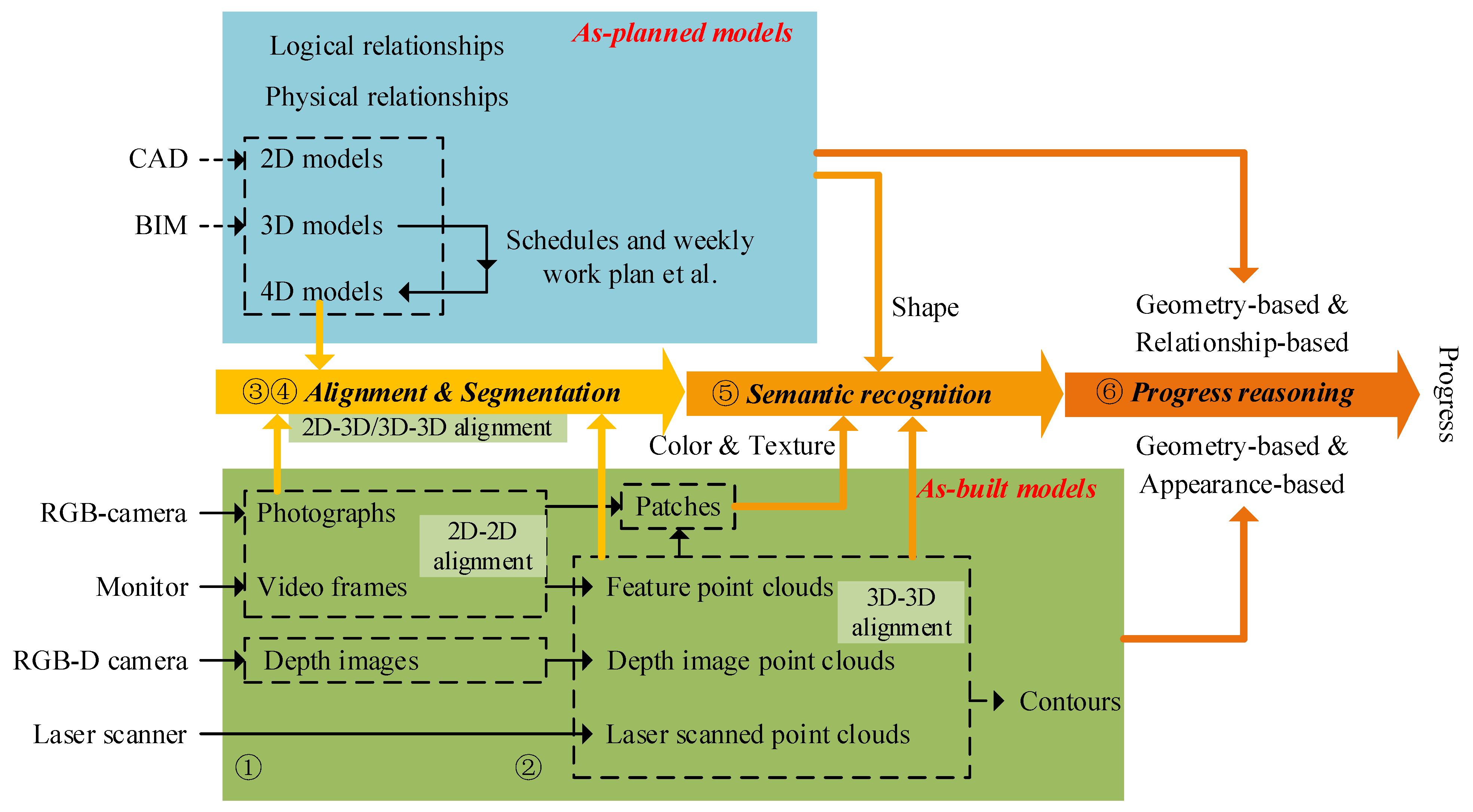
- Direct as-planned information: 2D/3D/4D models are widely known as the as-planned information which depict the planned process and final states, and the core purpose of these as-planned models, during the 3D reconstruction process, is to serve as a reference standard. Schedules and weekly work plan representing project execute process are usually combined with 3D models to form 4D models. Physical relationships represent the spatial connection between geometric primitives (including aggregation, topological and directional relationships) [24], while logical relationships represent the sequential relationship among building components due to procedural or technical requirements, similar to the construction sequence under the constraint of the activity-on-arrow network. Both physical and logical relationships can be used to assist decision-making [25].
- Direct as-build information: Image is one of the most common as-build information including photographs, videos, and depth images. With the recent advances in smart devices and camera-equipped platforms, an exponential growth in the volume of images and videos that are recorded on construction sites [12,26]. Compared with ordinary photographs, depth images/RGB-D images generated by the range camera contain depth information, which makes them easy to generate as-build point clouds. Furthermore, laser scanned point cloud is also a common way to represent as-build models.
- Derived information: Derived information comes from images or point clouds and provides support for the construction process reasoning. First, the point clouds derived from images or videos are a kind of derived information. Presently, taking real-time videos or time-lapse images and then aligning these sequential frames/images via feature detection, matching, and homography transformation to generate point clouds are common practices [12,27]. In addition, if point clouds are projected onto the plane which runs parallel to the floor/wall, contours of buildings can be extracted through the algorithm from Suzuki [28,29] to reason walls, doors, windows or other apertures [29]. Moreover, there is also a lot of useful information generated from images. For example, some researchers project 3D model elements onto image planes and the images are segmented into patches for the progress reasoning [30]. Furthermore, the image patches can be used for creating multiple discriminative material classification model and the Construction Material Library (CML) for the progress reasoning [31].
3.2. Image Collection and 3D Point Cloud Generation
3.2.1. Data Acquisition Device
3.2.2. Data Type
- Time-lapse images/videos from fixed camera: Fixing the camera position means simplifying complicated registration process. As long as the camera coordinates and camera shooting direction are obtained, the images can be registered with the BIM model after simple rotation and scaling. Although this means a lack of flexibility in response to occlusions caused by changing structures, the benefits of always-on-demand images provide the possibility for fast and responsive assessment [32]. However, to reduce occlusion, it is necessary to increase the number of cameras shooting from multiple angles [33,34], as shown in Figure 2, which raises new questions—how to arrange multiple cameras and how to deal with data conflicts between cameras. In addition, the cameras need to be fixed on a stable object, which sometimes proves difficult. In addition, Golparvar-Fard et al. [33] found that small errors will significantly affect registration and minimize the allocated image area for each element, making the task of recognition much more challenging.
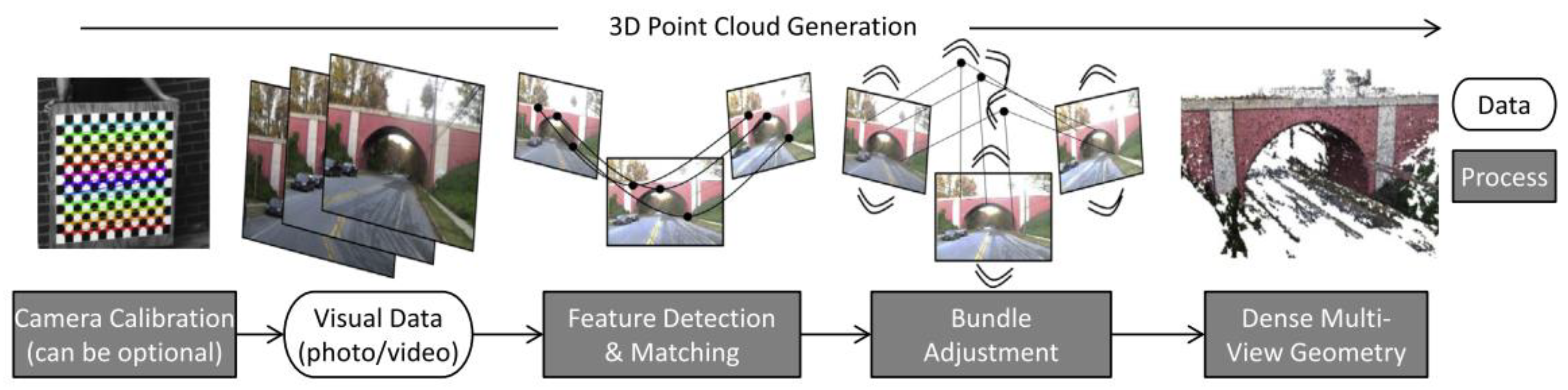
- Unordered image sets: Unordered image sets can be taken from any location, so that almost all corners can be captured without occlusions. These images are usually taken by construction managers, owner representatives, contractors, and subcontractors and have capacity to enable complete visualization of a construction site [3]. However, developing computer vision and image processing techniques that can effectively operate on such imagery is a huge challenge [3]. Golparvar-Fard et al. [3,35] came up with a way—extract SIFT feature points from continuous images, match them to estimate the fundamental matrixes using the RANSAC algorithm, and use the SfM principle to generate point clouds, as shown in Figure 3. In this method, although the image sets can be unordered, the images in an image set are orderly, and a certain proportion of repeating regions among these images is needed to extract corresponding SIFT points. In addition, the user needs to initially register the as-planned and as-built models [35]. When there are many unordered image sets, it is necessary to manually record the camera position and external parameters, and each image set requires an initial registration that is quite troublesome. Moreover, to avoid occlusion and cover all observed objects, a large amount of overlap is necessary, which is almost impossible for manual acquisition. Some researchers use camera-equipped Unmanned Aerial Vehicles (UAVs) to professionally take images and document them [36,37], which allow for a wider range of views, especially from above, and the GPS coordinates and camera orientation are known in most cases. Even so, it is still very difficult and is tedious to find the exact views in BIM due to the inaccurate GPS coordinates especially in the vertical axis [12].
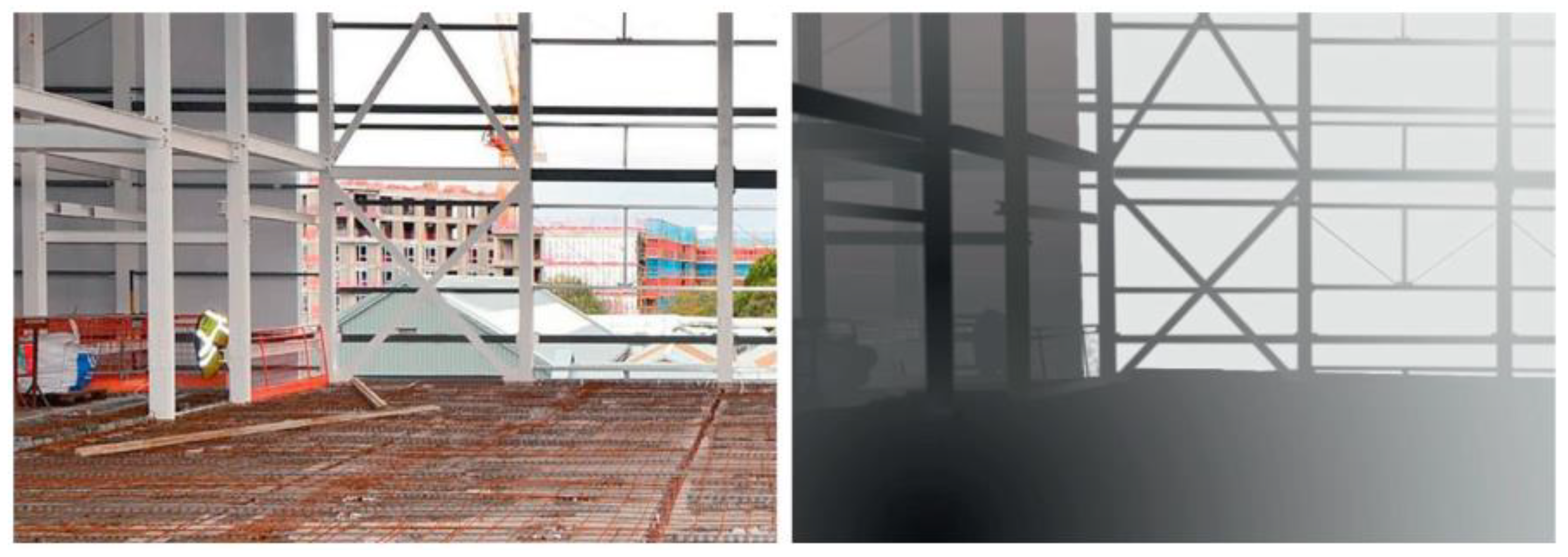
- Depth images: Depth images, generated from range cameras/RGB-D cameras, contain not only RGB colors but also depth information, as shown in Figure 4. Similar to the point cloud generated by laser scanners, the 3D point cloud model of the observed object can be generated directly from the depth images. The range camera has attracted the attention of many scholars because of its low cost and portability. However, due to the limited shooting range, it is only suitable for indoor shooting, not for large-scale image acquisition [38,39].
3.3. Image-to-BIM Alignment
- 3D–2D registration-based: Monitoring the construction process using fixed cameras without pan/tilt/zoom is one of the most convenient ways. Because once the user initially registers the as-planned and as-built models, the correspondence between the photograph and the virtual model would be set for all subsequent images [33]. Many scholars superimpose 3D visual models on images in Augmented Reality (AR) or Visual Reality (VR) environments [3,33,41]. Ideally, all visual models could be projected on the image plane and fully registered with the image. However, the outdoor camera is susceptible to environmental influences such as gravity and transverse winds, which can easily lead to the failure of automatic registration. Therefore, a set of key points with known positions in the photograph and the 3D visual environment is required to achieve more accurate registration [32].
- Feature point-based: To avoid the problem of occlusion caused by fixing cameras, some scholars explore the methods of movable cameras. Golparvar-Fard et al. [3,35] studied a method of extracting SIFT feature points from unordered image sets. By identifying the common feature points of overlapping region, these images were registered with each other to generate feature point cloud. Then, the images and the virtual model were registered by aligning the feature point cloud with the 3D virtual model in 4D Augment Reality (D4AR) environment. They realized the image-to-BIM alignment through the registration of image-to-point cloud and point cloud-to-BIM. In addition, many automated methods have also been proposed to register point clouds with BIM models. Bueno et al. [42] presented a novel method (4-plane congruent set algorithm) for automatic registration of as-is 3D point clouds with 3D BIM models. Lei et al. [43] proposed a 3D patch registration approach based on Convolutional Neural Network (CNN) deep-learning algorithm for integrating sequential models in support of progress monitoring.
- Depth image-based: Compared with the above method, the image-to-BIM alignment method based on the depth image simplifies the process of image registration and point cloud generation because the depth information is included in the depth image. In the research of Pučko et al. [38], workers captured all workplaces inside and outside of the building in real time and record partial point clouds, their locations, and time stamps by Kinect (helmet-mounted scanner). Then by manually picking the equivalent points, the partial point clouds were registered and merged into a complete 4D as-built point cloud of a building under construction. Finally, the image-to-BIM alignment was realized using a software developed at the University of Maribor [10]. Although the early process of image registration and point cloud generation has been simplified, the process of picking the equivalent points manually was not subtracted, which requires a lot of manual work. It is time-consuming, sometimes it must be repeated, the result is not precise and leads to limited usefulness.
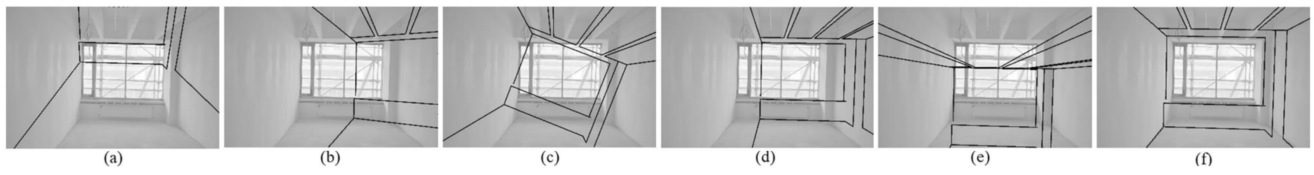
- Perspective-based: This method uses the relationship among points, lines, and surfaces in images to directly register the image with BIM. For example, Kropp et al. [4] and Asadi et al. [44] proposed a new method to register images with BIM using perspective alignment for indoor monitoring of construction, as shown in Figure 5. First, video frames were captured with a monocular camera system to create as-built data of the current construction status. Second, the first frame was registered initially with the BIM model by superimposing the wire frame model on it in an AR manner. Then the fine correspondence between the model and the as-built scene was calculated from line candidates extracted by scanning as-built images RoI. Although only the first frame needs manual alignment, each video needs manual processing, which obviously requires a lot of manual labor. Because each room needs a separate video, and they need to be shot daily. Similarly, Fernandez-Labrador et al. [45] propose a novel procedure for 3D layout recovery of indoor scenes from single 360° panoramic images. The proposed method combined geometric reasoning and deep learning to generate a pruned set of lines belonging to the main structure of the room, from which they extracted candidate corners and generated layout hypotheses. These alignment methods register the as-built image directly with the as-planned model without the assistance of point clouds. However, these technologies only have been applied in the indoor decoration stage with little occlusion, which may not be applicable to the outdoor scenes.
3.4. Point Cloud Segmentation
3.5. Point Cloud Semantic Recognition
3.6. Progress Reasoning
- Based on the 3D space occupancy by the point clouds: Braun et al. [25] split the BIM element surface into 2D raster cells and verified the progress information by the number of points extracted for each raster cell within a certain distance before and behind the BIM element surface. Omar et al. [1] created internal and external surface planes for BIM model and measured the true column heights by the point cloud between the external and internal surface boundaries. Golparvar-Fard et al. [35] traversed and labeled for expected progress visibility and a machine-learning scheme built upon a Bayesian probabilistic model was proposed that automatically detects physical progress.
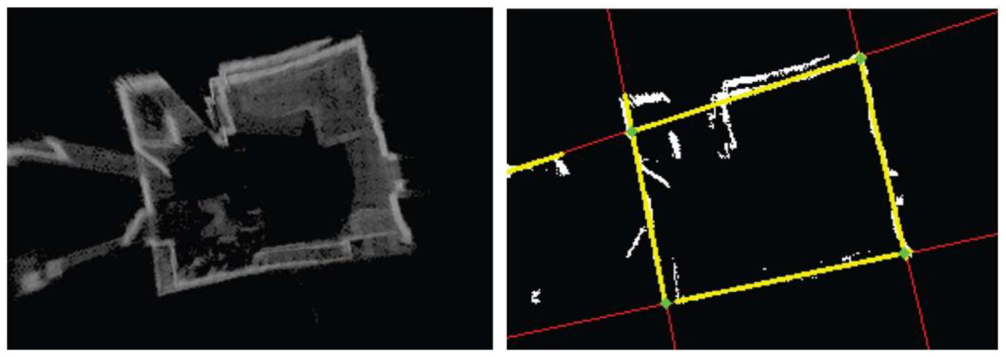
- Based on the 2D plane projection of the point clouds: Rebolj et al. [10] and Pučko et al. [38] projected a BIM element to three orthogonal planes and rasterized them within a regular grid. Then, they projected the points in the element’s proximity onto the same grids and the area of grid-cells containing projected points is considered to be a covered area. Finally, they identified the existing elements by assessing the percentage of elements’ surface being covered by the point cloud. Volk et al. [29] projected the point clouds onto a plane which runs parallel to the floor generating a heat map, from which a closed loop providing the room’s floor plan were construct, as shown in Figure 8. On this basis, 3D points were projected onto the walls creating an image per wall to extract contours which were characterized into windows, doors, or other apertures.
- Based on the image changes of 3D–2D projection area: Kim et al. [60] applied 3D CAD-based image mask filters to identify the construction progress of a cable-stayed bridge on background with little noise, which may not be appropriate for complex environments. Zhu and Brilakis [61] identified the segmented image region using machine-learning techniques to determine whether the region was composed of concrete or not. The concrete identified by this method is a whole area, not refined to the component. For this defect, Ibrahim et al. [32] segmented the image into a set of discrete component masks and analyzed the texture or color changes of specific regions of interest related to each component to infer the timings of significant events. Unfortunately, most of these changes were related to spurious lighting and other variable conditions, such as equipment, or scaffolding being moved. Then Han and Golparvar-Fard [30] proposed a new appearance-based material classification method for monitoring construction progress deviations at the operational-level. They used pre-trained multiclass material classifier to recognize the texture of the region of interest, rather than only based on the change of color. Afterward, Han et al. [62] combined the geometry-based and appearance-based reasoning methods for detecting construction progress, which had the potential to provide more frequent progress measures.
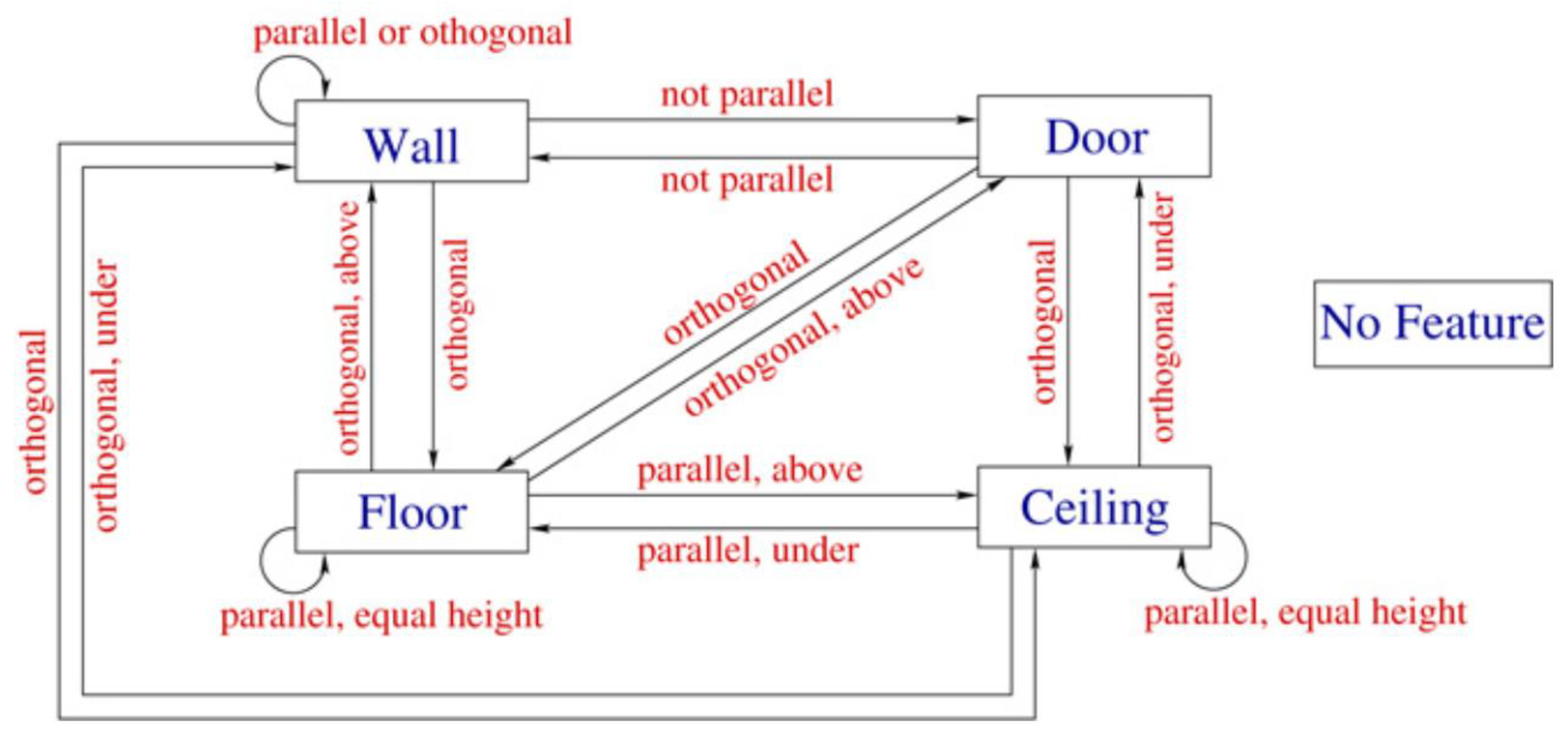
- Based on the relationships of geometric primitives: Sometimes occlusions are inevitable. It is a wise choice to use auxiliary information to reason progress, because it can greatly reduce the duplication of effort in the data collection phase and the ambiguity of recognition results. The auxiliary information includes physical relationships (aggregation, topological and directional relationships) and logical relationships between objects or geometric primitives. Nuchter and Hertzberg [63] represented the knowledge model of the spatial relationships with a semantic net. Nguyen et al. [64] automatically derive topological relationships between solid objects or geometric primitives with a 3D solid CAD model. Braun et al. [25] attributed these relationships to technological dependencies and represented these dependencies with graphs (nodes for building elements and edges for dependencies). However, there is controversy about the use of ancillary information. For example, Ibrahim et al. [32] pointed out this approach would not be totally reliable, since the only way to truly gain confidence that a component is finished is to visually verify it. They suggested a combination of multiple sources of image to increase the overall reliability.
4. Knowledge Gaps and Challenges
4.1. Occlusions and Limited Visibility
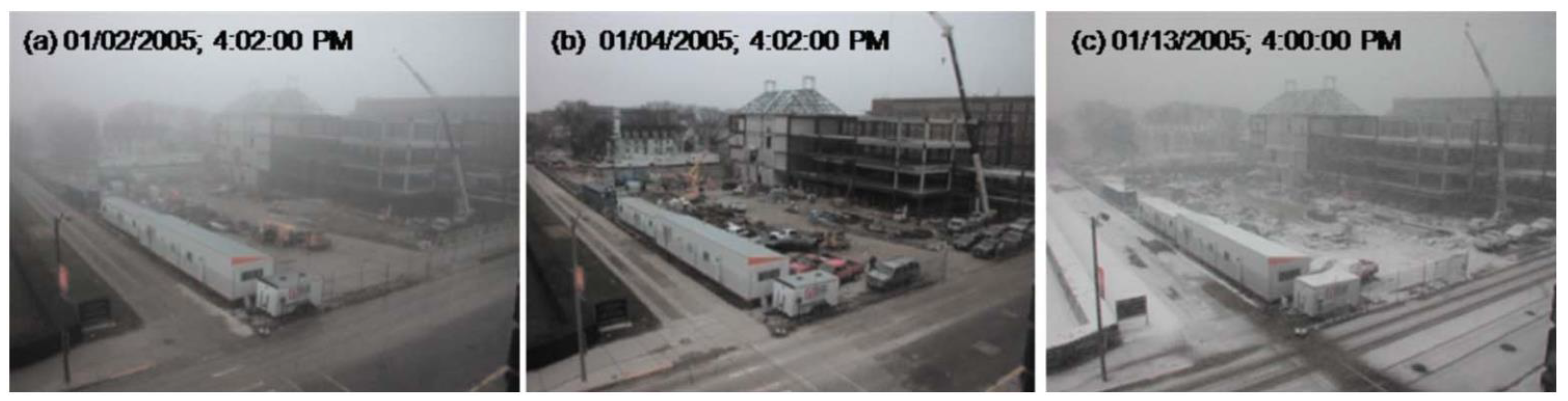
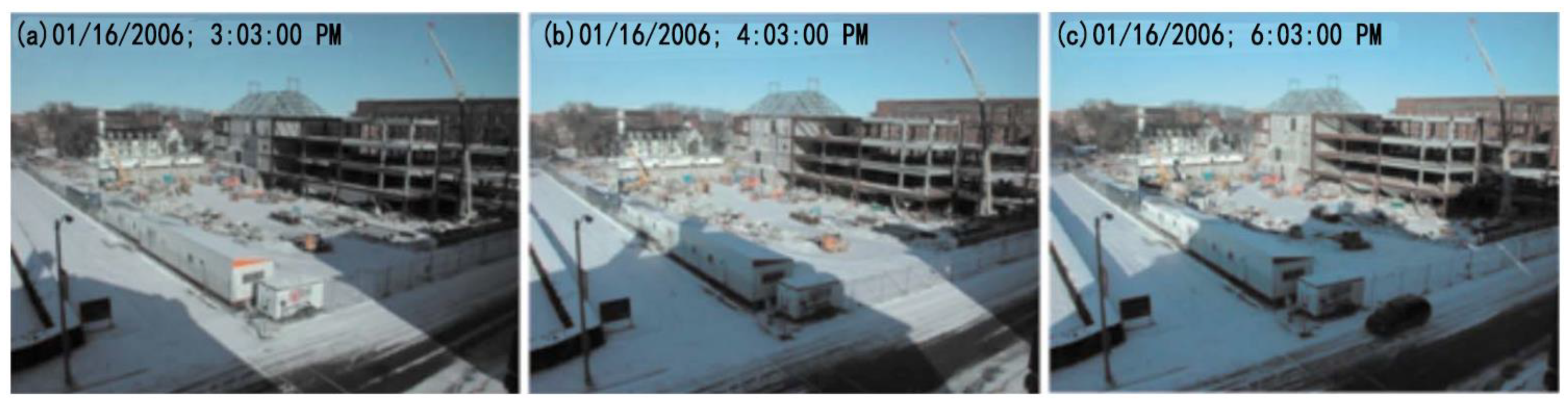
4.2. Lighting and Shadow Conditions
4.3. Indoor 3D Reconstruction
4.4. Non-Automated Image-to-BIM Registration
- Time-lapse images or videos from fixed camera: Since the cameras are fixed, it is convenient to manually register each camera only once. However, the scenes captured by this method are so limited that it is only suitable for shooting large-scale scenes. Therefore, it is necessary to equip multiple high-resolution cameras at the construction site. Even so, they are still severely affected by lighting conditions and there are still many unavoidable occlusions [33].
- Unordered images or videos: To avoid occlusion, some scholars proposed to free the camera and use unordered images that collected by field personal. If the camera is not calibrated, and the position and orientation are unknown, registration is almost impossible. Many researchers took video clips to generate partial point clouds, and then integrate different parts to form a global 3D model. However, each part needs to record the initial state of the camera and be registered. Usually, many clips need to be taken to cover all the details of a building, which is very troublesome [35,59].
- Image sequences taken with UAVs: Images sequences are usually taken by camera-equipped UAVs and come with GPS coordinates and camera orientation which can used to align the point clouds and BIM. Ideally, only the starting position needs to be registered and all architectural details could be captured at once. However, the effect was not good in practice due to the inaccurate GPS coordinates especial in the vertical axis. The longer the flight path means the greater the accumulated deviation, and it is difficult to build accurate point clouds.
4.5. Troubles of Point Cloud
4.6. Disputes about Prior Information
5. Research Findings
- Image has more advantages than other forms of data. There are various types of automatic acquisition technologies, which can be roughly divided into Enhanced IT technologies, Geospatial technologies, Imaging technologies, and Augmented reality [20]. However, the imaging technologies, especially photography and video shooting, have the advantages of intuitive, rich information, accurate, low cost, and low technical requirements, which is congenitally advantageous to be accepted by construction companies.
- Easy and cheap access to massive image data. The acquisition of reliable data is supported by the development of hardware, including camera, monitor, storage device, smartphone, UAV, etc. Daily images can not only be collected systematically, but also recorded by workers on site, due to the diffusion of devices with built-in cameras. Abundant and sufficient data means that enough information can be extracted in theory, while information extraction is up to the software.
- Rapid development of software technology. The booming new image processing technologies, especially the ones based on deep learning, have been fully and deeply applied in biomedicine, aerospace, transportation, public security, and other industries. However, in the field of AEC, the research and application of these technologies are still in its infancy.
- Most of the research is based on the point cloud, rather than the image itself. The methods without point cloud are still worth exploring, for example, VR-based registration and object detection-based reconstruction.
- New technologies that can be combined with image-based 3D reconstruction have emerged. With the vigorous development of hardware, software, algorithms, and data in computers and related industries, various new technologies have emerged. These technologies have made huge breakthroughs and are sought after by researchers. Many scholars have begun to integrate these emerging technologies with existing 3D reconstruction technologies and have achieved amazing results.
6. Discussion
6.1. Contribution
- A more comprehensive technology roadmap is created. Reading and summarizing the previous work, the authors find that the relevant literature only focuses on point cloud-based methods or perspective-based methods, which are applied to outdoor and indoor monitoring, respectively. Few people analyze them together in one article. This paper breaks the barriers between them and obtains a comprehensive technology roadmap. The technical roadmap is new and covers a wider range of methods, which provides a reference for the integration of indoor and outdoor construction progress monitoring.
- The knowledge gap ignored by most scholars is highlighted. In the fourth part, the main knowledge gaps and challenges in the process of 3D reconstruction are analyzed, and the solutions are indicated. In addition to the problems concerned by scholars, this part also points out the problems of point cloud and prior knowledge, which are less concerned by scholars.
6.2. Practical Guidance
6.3. BIM Technology
6.4. Future Development Trends
6.4.1. Combination with VR and AR
6.4.2. Combination with Deep Learning
6.4.3. Combination with Big Data
7. Concluding Remarks
Author Contributions
Funding
Institutional Review Board Statement
Informed Consent Statement
Data Availability Statement
Conflicts of Interest
Appendix A

| Process | Type | References |
|---|---|---|
| As-built data | Photographs | [1,3,12,17,25,27,28,30,32,35,45,59,60,61,62,72,73] |
| Video frames | [4,12,17,26,27,33,41,62,74] | |
| Feature point clouds from image | [1,3,12,25,26,30,35,62] | |
| Laser scanned/depth image point clouds | [17,24,27,29,38,62] | |
| Patches | [12,30,32,60,62] | |
| Contours | [29] | |
| As-planned data | 3D models | All references |
| 4D models | [4,12,30,32,38,60,62] | |
| Logical/physical relationships | [24,25] | |
| Alignment | 3D–2D registration-based | [3,32,33,41] |
| Feature point-based | [3,35,42,43,62] | |
| Depth image-based | [10,38] | |
| Perspective-based | [4,44,45] | |
| Point cloud segmentation | Clustering-based | [47,48] |
| Edge-based | [49,50] | |
| Region-based | [51] | |
| Graph-based | [50,52] | |
| Model fitting-based | [53,54] | |
| Hybrid | [55] | |
| Point cloud semantic recognition | Point cloud semantic recognition | [56,57,58,59] |
| Progress reasoning | Based on the 3D space occupancy by the point clouds | [1,25,35] |
| Based on the 2D plane projection of the point clouds | [10,29,38] | |
| Based on the image changes of 3D–2D projection area | [30,32,60,61,62] | |
| Based on the relationships of geometric primitives | [25,32,63,64] |
References
- Omar, H.; Mahdjoubi, L.; Kheder, G. Towards an automated photogrammetry-based approach for monitoring and controlling construction site activities. Comput. Ind. 2018, 98, 172–182. [Google Scholar] [CrossRef]
- Salehi, S.A.; Yitmen, I. Modeling and analysis of the impact of BIM-based field data capturing technologies on automated construction progress monitoring. Int. J. Civ. Eng. 2018, 16, 1669–1685. [Google Scholar] [CrossRef]
- Golparvar-Fard, M.; Peña-Mora, F.; Savarese, S. Application of D4AR–a 4-dimensional augmented reality model for automating construction progress monitoring data collection, processing and communication. J. Inf. Technol. Constr. 2009, 14, 129–153. [Google Scholar]
- Kropp, C.; Koch, C.; König, M. Interior construction state recognition with 4D BIM registered image sequences. Autom. Constr. 2018, 86, 11–32. [Google Scholar] [CrossRef]
- Czerniawski, T.; Leite, F. Automated digital modeling of existing buildings: A review of visual object recognition methods. Autom. Constr. 2020, 113, 103131. [Google Scholar] [CrossRef]
- Han, X.-F.; Laga, H.; Bennamoun, M. Image-based 3D object reconstruction: State-of-the-art and trends in the deep learning era. IEEE Trans. Pattern Anal. Mach. Intell. 2021, 43, 1578–1604. [Google Scholar] [CrossRef] [PubMed] [Green Version]
- Rankohi, S.; Waugh, L. Image-based modeling approaches for projects status comparison. In Proceedings of the CSCE 2014 General Conference, Halifax, NS, Canada, 28–31 May 2014; pp. 1–10. [Google Scholar]
- Chu, C.-C.; Nandhakumar, N.; Aggarwal, J. Image segmentation using laser radar data. Pattern Recognit. 1990, 23, 569–581. [Google Scholar] [CrossRef]
- Bechtold, S.; Höfle, B. Helios: A multi-purpose lidar simulation framework for research, planning and training of laser scanning operations with airborne, ground-based mobile and stationary platforms. ISPRS Ann. Photogramm. Remote Sens. Spat. Inf. Sci. 2016, 3, 161–168. [Google Scholar] [CrossRef] [Green Version]
- Rebolj, D.; Pučko, Z.; Babič, N.Č.; Bizjak, M.; Mongus, D. Point cloud quality requirements for scan-vs-BIM based automated construction progress monitoring. Autom. Constr. 2017, 84, 323–334. [Google Scholar] [CrossRef]
- Hong, S.; Park, I.; Lee, J.; Lim, K.; Choi, Y.; Sohn, H.-G. Utilization of a terrestrial laser scanner for the calibration of mobile mapping systems. Sensors 2017, 17, 474. [Google Scholar] [CrossRef] [Green Version]
- Han, K.K.; Golparvar-Fard, M. Potential of big visual data and building information modeling for construction performance analytics: An exploratory study. Autom. Constr. 2017, 73, 184–198. [Google Scholar] [CrossRef] [Green Version]
- Lowe, D.G. Distinctive image features from scale-invariant keypoints. Int. J. Comput. Vis. 2004, 60, 91–110. [Google Scholar] [CrossRef]
- Bay, H.; Tuytelaars, T.; Van Gool, L. Surf: Speeded up robust features. In Computer Vision—ECCV 2006, Proceedings of the 9th European Conference on Computer Vision, Graz, Austria, 7–13 May 2006; Springer: Berlin/Heidelberg, Germany, 2006; pp. 404–417. [Google Scholar] [CrossRef]
- Fischler, M.A.; Bolles, R.C. Random sample consensus: A paradigm for model fitting with applications to image analysis and automated cartography. Commun. ACM 1981, 24, 381–395. [Google Scholar] [CrossRef]
- Ullman, S. The interpretation of structure from motion. Proc. R. Soc. London Ser. B Boil. Sci. 1979, 203, 405–426. [Google Scholar] [CrossRef]
- Fathi, H.; Dai, F.; Lourakis, M. Automated as-built 3D reconstruction of civil infrastructure using computer vision: Achievements, opportunities, and challenges. Adv. Eng. Inform. 2015, 29, 149–161. [Google Scholar] [CrossRef]
- Pătrăucean, V.; Armeni, I.; Nahangi, M.; Yeung, J.; Brilakis, I.; Haas, C. State of research in automatic as-built modelling. Adv. Eng. Inform. 2015, 29, 162–171. [Google Scholar] [CrossRef] [Green Version]
- Bilal, M.; Oyedele, L.O.; Qadir, J.; Munir, K.; Ajayi, S.O.; Akinade, O.; Owolabi, H.A.; Alaka, H.A.; Pasha, M. Big data in the construction industry: A review of present status, opportunities, and future trends. Adv. Eng. Inform. 2016, 30, 500–521. [Google Scholar] [CrossRef]
- Omar, T.; Nehdi, M.L. Data acquisition technologies for construction progress tracking. Autom. Constr. 2016, 70, 143–155. [Google Scholar] [CrossRef]
- El-Omari, S.; Moselhi, O. Data acquisition from construction sites for tracking purposes. Eng. Constr. Arch. Manag. 2009, 16, 490–503. [Google Scholar] [CrossRef]
- Zhu, Z.; Brilakis, I. Comparison of optical sensor-based spatial data collection techniques for civil infrastructure modeling. J. Comput. Civ. Eng. 2009, 23, 170–177. [Google Scholar] [CrossRef]
- Ekanayake, B.; Wong, J.K.-W.; Fini, A.A.F.; Smith, P. Computer vision-based interior construction progress monitoring: A literature review and future research directions. Autom. Constr. 2021, 127, 103705. [Google Scholar] [CrossRef]
- Tang, P.; Huber, D.; Akinci, B.; Lipman, R.; Lytle, A. Automatic reconstruction of as-built building information models from laser-scanned point clouds: A review of related techniques. Autom. Constr. 2010, 19, 829–843. [Google Scholar] [CrossRef]
- Braun, A.; Tuttas, S.; Borrmann, A.; Stilla, U. A concept for automated construction progress monitoring using BIM-based geometric constraints and photogrammetric point clouds. J. Inf. Technol. Constr. 2015, 20, 68–79. [Google Scholar]
- Brilakis, I.; Fathi, H.; Rashidi, A. Progressive 3D reconstruction of infrastructure with videogrammetry. Autom. Constr. 2011, 20, 884–895. [Google Scholar] [CrossRef]
- El-Omari, S.; Moselhi, O. Integrating automated data acquisition technologies for progress reporting of construction projects. Autom. Constr. 2011, 20, 699–705. [Google Scholar] [CrossRef] [Green Version]
- Koch, C.; Paal, S.; Rashidi, A.; Zhu, Z.; König, M.; Brilakis, I. Achievements and challenges in machine vision-based inspection of large concrete structures. Adv. Struct. Eng. 2014, 17, 303–318. [Google Scholar] [CrossRef]
- Volk, R.; Luu, T.H.; Mueller-Roemer, J.S.; Sevilmis, N.; Schultmann, F. Deconstruction project planning of existing buildings based on automated acquisition and reconstruction of building information. Autom. Constr. 2018, 91, 226–245. [Google Scholar] [CrossRef]
- Han, K.; Golparvar-Fard, M. Appearance-based material classification for monitoring of operation-level construction progress using 4D BIM and site photologs. Autom. Constr. 2015, 53, 44–57. [Google Scholar] [CrossRef]
- Xiao, D. Application and development of BIM Technology in spatial structure. Master’s Thesis, Shanghai Jiaotong University, Shanghai, China, 2015. [Google Scholar]
- Ibrahim, Y.; Lukins, T.; Zhang, X.; Trucco, E.; Kaka, A. Towards automated progress assessment of workpackage components in construction projects using computer vision. Adv. Eng. Inform. 2009, 23, 93–103. [Google Scholar] [CrossRef]
- Golparvar-Fard, M.; Peña-Mora, F.; Arboleda, C.A.; Lee, S. Visualization of construction progress monitoring with 4D simulation model overlaid on time-lapsed photographs. J. Comput. Civ. Eng. 2009, 23, 391–404. [Google Scholar] [CrossRef] [Green Version]
- Leung, S.-W.; Mak, S.; Lee, B.L. Using a real-time integrated communication system to monitor the progress and quality of construction works. Autom. Constr. 2008, 17, 749–757. [Google Scholar] [CrossRef]
- Golparvar-Fard, M.; Peña-Mora, F.; Savarese, S. Automated progress monitoring using unordered daily construction photographs and IFC-based building information models. J. Comput. Civ. Eng. 2015, 29, 04014025. [Google Scholar] [CrossRef]
- Ham, Y.; Han, K.K.; Lin, J.J.; Golparvar-Fard, M. Visual monitoring of civil infrastructure systems via camera-equipped unmanned aerial vehicles (UAVs): A review of related works. Vis. Eng. 2016, 4, 1. [Google Scholar] [CrossRef] [Green Version]
- Álvares, J.S.; Costa, D.B. Literature review on visual construction progress monitoring using unmanned aerial vehicles. In Proceedings of the 26th Annual Conference of the International Group for Lean Construction, IGLC, Chennai, India, 16–22 July 2018; pp. 669–680. [Google Scholar]
- Pučko, Z.; Šuman, N.; Rebolj, D. Automated continuous construction progress monitoring using multiple workplace real time 3D scans. Adv. Eng. Inform. 2018, 38, 27–40. [Google Scholar] [CrossRef]
- Czerniawski, T.; Leite, F. 3D facilities: Annotated 3D reconstructions of building facilities. In Transactions on Petri Nets and Other Models of Concurrency XV; Springer: Berlin/Heidelberg, Germany, 2018; Volume 10863, pp. 186–200. [Google Scholar]
- Pour Rahimian, F.; Seyedzadeh, S.; Oliver, S.; Rodriguez, S.; Dawood, N. On-demand monitoring of construction projects through a game-like hybrid application of BIM and machine learning. Autom. Constr. 2020, 110, 103012. [Google Scholar] [CrossRef]
- Kim, H.; Kano, N. Comparison of construction photograph and VR image in construction progress. Autom. Constr. 2008, 17, 137–143. [Google Scholar] [CrossRef]
- Bueno, M.; Bosché, F.; González-Jorge, H.; Martínez-Sánchez, J.; Arias, P. 4-Plane congruent sets for automatic registration of as-is 3D point clouds with 3D BIM models. Autom. Constr. 2018, 89, 120–134. [Google Scholar] [CrossRef]
- Lei, L.; Zhou, Y.; Luo, H.; Love, P.E. A CNN-based 3D patch registration approach for integrating sequential models in support of progress monitoring. Adv. Eng. Inform. 2019, 41, 100923. [Google Scholar] [CrossRef]
- Asadi, K.; Ramshankar, H.; Noghabaei, M.; Han, K. Real-time image localization and registration with BIM Using perspective alignment for indoor monitoring of construction. J. Comput. Civ. Eng. 2019, 33, 04019031. [Google Scholar] [CrossRef]
- Fernandez-Labrador, C.; Perez-Yus, A.; Lopez-Nicolas, G.; Guerrero, J.J. Layouts from panoramic images with geometry and deep learning. IEEE Robot. Autom. Lett. 2018, 3, 3153–3160. [Google Scholar] [CrossRef] [Green Version]
- Wang, Q.; Tan, Y.; Mei, Z. Computational methods of acquisition and processing of 3D point cloud data for construction applications. Arch. Comput. Methods Eng. 2019, 27, 479–499. [Google Scholar] [CrossRef]
- Lu, X.; Yao, J.; Tu, J.; Li, K.; Li, L.; Liu, Y. Pairwise linkage for point cloud segmentation. ISPRS Ann. Photogramm. Remote Sens. Spat. Inf. Sci. 2016, 3, 201–208. [Google Scholar] [CrossRef] [Green Version]
- Zeng, S.; Chen, J.; Cho, Y.K. User exemplar-based building element retrieval from raw point clouds using deep point-level features. Autom. Constr. 2020, 114, 103159. [Google Scholar] [CrossRef]
- Wani, M.A.; Arabnia, H.R. Parallel edge-region-based segmentation algorithm targeted at reconfigurable multiring network. J. Supercomput. 2003, 25, 43–62. [Google Scholar] [CrossRef]
- Chen, J.; Kira, Z.; Cho, Y.K. Deep learning approach to point cloud scene understanding for automated scan to 3D reconstruction. J. Comput. Civ. Eng. 2019, 33, 04019027. [Google Scholar] [CrossRef]
- Vo, A.-V.; Truong-Hong, L.; Laefer, D.F.; Bertolotto, M. Octree-based region growing for point cloud segmentation. ISPRS J. Photogramm. Remote Sens. 2015, 104, 88–100. [Google Scholar] [CrossRef]
- Strom, J.; Richardson, A.; Olson, E. Graph-based segmentation for colored 3D laser point clouds. In Proceedings of the 2010 IEEE/RSJ International Conference on Intelligent Robots and Systems, Taipei, Taiwan, 18–22 October 2010; pp. 2131–2136. [Google Scholar]
- Maas, H.-G.; Vosselman, G. Two algorithms for extracting building models from raw laser altimetry data. ISPRS J. Photogramm. Remote Sens. 1999, 54, 153–163. [Google Scholar] [CrossRef]
- Chen, D.; Zhang, L.; Mathiopoulos, P.T.; Huang, X. A methodology for automated segmentation and reconstruction of urban 3-D buildings from ALS point clouds. IEEE J. Sel. Top. Appl. Earth Obs. Remote Sens. 2014, 7, 4199–4217. [Google Scholar] [CrossRef]
- Vieira, M.; Shimada, K. Surface mesh segmentation and smooth surface extraction through region growing. Comput. Aided Geom. Des. 2005, 22, 771–792. [Google Scholar] [CrossRef]
- Antonello, M.; Wolf, D.; Prankl, J.; Ghidoni, S.; Menegatti, E.; Vincze, M. Multi-view 3D entangled forest for semantic seg-mentation and mapping. In Proceedings of the IEEE International Conference on Robotics and Automation (ICRA), Los Alamitos, CA, USA, 21–26 May 2018; pp. 1855–1862. [Google Scholar]
- Posada, L.F.; Velasquez-Lopez, A.; Hoffmann, F.; Bertram, T. Semantic mapping with omnidirectional vision. In Proceedings of the 2018 IEEE International Conference on Robotics and Automation (ICRA), Los Alamitos, CA, USA, 21–26 May 2018; pp. 1901–1907. [Google Scholar]
- Adán, A.; Quintana, B.; Prieto, S.; Bosché, F. An autonomous robotic platform for automatic extraction of detailed semantic models of buildings. Autom. Constr. 2020, 109, 102963. [Google Scholar] [CrossRef]
- Dimitrov, A.; Golparvar-Fard, M. Vision-based material recognition for automated monitoring of construction progress and generating building information modeling from unordered site image collections. Adv. Eng. Inform. 2014, 28, 37–49. [Google Scholar] [CrossRef]
- Kim, C.; Kim, B.; Kim, H. 4D CAD model updating using image processing-based construction progress monitoring. Autom. Constr. 2013, 35, 44–52. [Google Scholar] [CrossRef]
- Zhu, Z.; Brilakis, I. Parameter optimization for automated concrete detection in image data. Autom. Constr. 2010, 19, 944–953. [Google Scholar] [CrossRef]
- Han, K.; DeGol, J.; Golparvar-Fard, M. Geometry- and appearance-based reasoning of construction progress monitoring. J. Constr. Eng. Manag. 2018, 144, 04017110. [Google Scholar] [CrossRef] [Green Version]
- Nuechter, A.; Hertzberg, J. Towards semantic maps for mobile robots. Robot. Auton. Syst. 2008, 56, 915–926. [Google Scholar] [CrossRef] [Green Version]
- Nguyen, T.-H.; Oloufa, A.A.; Nassar, K. Algorithms for automated deduction of topological information. Autom. Constr. 2005, 14, 59–70. [Google Scholar] [CrossRef]
- Chen, C.; Yang, B. Dynamic occlusion detection and inpainting of in situ captured terrestrial laser scanning point clouds sequence. ISPRS J. Photogramm. Remote Sens. 2016, 119, 90–107. [Google Scholar] [CrossRef]
- Hou, X.; Zeng, Y.; Xue, J. Detecting structural components of building engineering based on deep-learning method. J. Constr. Eng. Manag. 2020, 146, 04019097. [Google Scholar] [CrossRef]
- Roh, S.; Aziz, Z.; Peña-Mora, F. An object-based 3D walk-through model for interior construction progress monitoring. Autom. Constr. 2011, 20, 66–75. [Google Scholar] [CrossRef]
- Kropp, C.; Koch, C.; Brilakis, I.; Knig, M. A framework for automated delay prediction of finishing works using video data and BIM-based construction simulation. In Proceedings of the 14th International Conference on Computing in Civil and Building Engineering (ICCCBE), Moscow, Russia, 27–29 June 2012. [Google Scholar]
- Hamledari, H.; McCabe, B.; Davari, S. Automated computer vision-based detection of components of under-construction indoor partitions. Autom. Constr. 2017, 74, 78–94. [Google Scholar] [CrossRef]
- Bortoluzzi, B.; Efremov, I.; Medina, C.; Sobieraj, D.; McArthur, J. Automating the creation of building information models for existing buildings. Autom. Constr. 2019, 105, 102838. [Google Scholar] [CrossRef]
- Li, Y.; Li, W.; Tang, S.; Darwish, W.; Hu, Y.; Chen, W. Automatic indoor as-built building information models generation by using low-cost rgb-d sensors. Sensors 2020, 20, 293. [Google Scholar] [CrossRef] [Green Version]
- Galantucci, R.A.; Fatiguso, F. Advanced damage detection techniques in historical buildings using digital photogrammetry and 3D surface anlysis. J. Cult. Herit. 2019, 36, 51–62. [Google Scholar] [CrossRef]
- Koch, C.; Georgieva, K.; Kasireddy, V.; Akinci, B.; Fieguth, P. A review on computer vision based defect detection and condition assessment of concrete and asphalt civil infrastructure. Adv. Eng. Inform. 2015, 29, 196–210. [Google Scholar] [CrossRef] [Green Version]
- Fang, Q.; Li, H.; Luo, X.; Ding, L.; Rose, T.; An, W.; Yu, Y. A deep learning-based method for detecting non-certified work on construction sites. Adv. Eng. Inform. 2018, 35, 56–68. [Google Scholar] [CrossRef]
- Almasi, M. An investigation on deep learning applications for 3D reconstruction of human movements. Invent. J. Res. Technol. Eng. Manag. 2020, 4, 1–8. [Google Scholar]
- Zhu, Z.; Ren, X.; Chen, Z. Integrated detection and tracking of workforce and equipment from construction jobsite videos. Autom. Constr. 2017, 81, 161–171. [Google Scholar] [CrossRef]
- Wu, H.; Zhao, J. An intelligent vision-based approach for helmet identification for work safety. Comput. Ind. 2018, 100, 267–277. [Google Scholar] [CrossRef]
- Fang, Q.; Li, H.; Luo, X.; Ding, L.; Luo, H.; Rose, T.M.; An, W. Detecting non-hardhat-use by a deep learning method from far-field surveillance videos. Autom. Constr. 2018, 85, 1–9. [Google Scholar] [CrossRef]
- Deng, H.; Hong, H.; Luo, D.; Deng, Y.; Su, C. Automatic indoor construction process monitoring for tiles based on BIM and computer vision. J. Constr. Eng. Manag. 2020, 146, 04019095. [Google Scholar] [CrossRef]
- Zhao, C.; Sun, L.; Stolkin, R. A fully end-to-end deep learning approach for real-time simultaneous 3D reconstruction and material recognition. In Proceedings of the 2017 18th International Conference on Advanced Robotics (ICAR), Hong Kong, China, 15 April 2017; pp. 75–82. [Google Scholar]
- Landrieu, L.; Simonovsky, M. Large-scale point cloud semantic segmentation with superpoint graphs. In Proceedings of the 2018 IEEE/CVF Conference on Computer Vision and Pattern Recognition, Institute of Electrical and Electronics Engineers (IEEE), Salt Lake, UT, USA, 18–22 June 2018; pp. 4558–4567. [Google Scholar]
- Acharya, D.; Khoshelham, K.; Winter, S. BIM-PoseNet: Indoor camera localisation using a 3D indoor model and deep learning from synthetic images. ISPRS J. Photogramm. Remote Sens. 2019, 150, 245–258. [Google Scholar] [CrossRef]


| Publication | Number of Articles |
|---|---|
| Advanced Engineering Informatics | 9 |
| Automation in Construction | 22 |
| IEEE Conference | 5 |
| ISPRS Journal of Photogrammetry and Remote Sensing | 5 |
| Journal of Computing in Civil Engineering | 4 |
| Journal of Construction Engineering and Management | 2 |
| Journal of Information Technology in Construction | 2 |
| Sensors (Basel) | 2 |
| Others | 15 |
| Total | 66 |
| Device | Raw Data Type | Cost | Technical Threshold | Portability | Resolution | Texture Representation | 3D Surfaces Reconstruction |
|---|---|---|---|---|---|---|---|
| Camera | Photograph | Low | Low | High | High | Rich | - |
| Smart devices | Photograph | Low | Low | High | High | Rich | - |
| Monitor | Video | Low | Low | Low | Medium | Rich | - |
| UAV | Video | High | High | Low | Medium | Rich | - |
| Laser scanner | Point cloud | High | High | Low | High | Limited | Automatic |
| Depth camera | Photograph and point cloud | Medium | Low | High | High | Rich | Automatic |
| Satellite | Remote sensing images | High | Low | - | Low | Medium | - |
| Segmentation Methodologies | Advantages | Disadvantages | Ref |
|---|---|---|---|
| Clustering-based | Easy to understand and implement | Accuracy problem: sensitive to the noise in data and is influenced by the definition of neighbor | [47,48] |
| Edge-based | Fast segmentation | Accuracy problem: sensitive to noise and uneven density of point clouds | [49,50] |
| Region-based | More accurate to noise | Over or under segmentation and accuracy of determining boundaries | [51] |
| Graph-based | Better on complex point cloud data with uneven density or noise | Cannot process in real time, and training or other system is required to assist process | [50,52] |
| Model fitting-based | |||
| Hough transform | Fast and robust with outliers | Slower and more sensitive to segmentation parameters | [53] |
| RANSAC | Fast and robust with outliers, can process a large amount of data | Accuracy when processing different point cloud sources | [54] |
| Hybrid | Take advantage of multiple approaches more accurate | Contain all disadvantages of selected approaches | [55] |
Publisher’s Note: MDPI stays neutral with regard to jurisdictional claims in published maps and institutional affiliations. |
© 2021 by the authors. Licensee MDPI, Basel, Switzerland. This article is an open access article distributed under the terms and conditions of the Creative Commons Attribution (CC BY) license (https://creativecommons.org/licenses/by/4.0/).
Share and Cite
Xue, J.; Hou, X.; Zeng, Y. Review of Image-Based 3D Reconstruction of Building for Automated Construction Progress Monitoring. Appl. Sci. 2021, 11, 7840. https://doi.org/10.3390/app11177840
Xue J, Hou X, Zeng Y. Review of Image-Based 3D Reconstruction of Building for Automated Construction Progress Monitoring. Applied Sciences. 2021; 11(17):7840. https://doi.org/10.3390/app11177840
Chicago/Turabian StyleXue, Jingguo, Xueliang Hou, and Ying Zeng. 2021. "Review of Image-Based 3D Reconstruction of Building for Automated Construction Progress Monitoring" Applied Sciences 11, no. 17: 7840. https://doi.org/10.3390/app11177840