Article

Optimization of the 2PRU-1PRS Parallel Manipulator Based on Workspace and Power Consumption Criteria

1
Department of Mechanical Engineering, University of the Basque Country (UPV/EHU), 48013 Bilbao, Spain
2
Department of Systems Engineering and Automation, University of the Basque Country (UPV/EHU), 48013 Bilbao, Spain
*
Author to whom correspondence should be addressed.
Appl. Sci. 2021, 11(17), 7770; https://doi.org/10.3390/app11177770
Submission received: 7 July 2021 / Revised: 9 August 2021 / Accepted: 17 August 2021 / Published: 24 August 2021
(This article belongs to the Topic Industrial Robotics)

Abstract

:
In the last few years, parallel manipulators are being increasingly studied and used for different applications. The performance of parallel manipulators is very sensitive to the geometric parameters, so it is essential to optimize them in order to obtain the desired function. We propose two optimization algorithms that consider the size and regularity of the workspace. The first one obtains the geometric parameters combination that results in the biggest and most regular workspace. The second method analyzes the geometric parameters combinations that result in an acceptable size of the workspace—even if it is not the biggest one—and finds out which ones result in the lowest power consumption. Even if the results vary depending on the application and trajectories studied, the proposed methodology can be followed to any type of parallel manipulator, application or trajectory. In this work we focus on the dimension optimization of the geometric parameters of the 2PRU-1PRS Multi-Axial Shaking Table (MAST) for automobile pieces testing purposes.

1. Introduction

If we compare parallel manipulators (PM) with serial manipulators, we observe that parallel manipulators have some interesting advantages, such as a higher stiffness all over the workspace (WS), better load/weight ratio and lower inertia. Nevertheless, parallel manipulators have also some disadvantages—more complex kinematics and dynamics and also more complex and smaller workspace.
In the last few years, parallel manipulators have been studied and used for applications where high stiffness, high speed and/or very good accuracy are required. Geometric parameters have a pronounced effect on these performance criteria of the parallel manipulators. Thus, the geometrical optimization of parallel manipulators is essential in order to obtain the desired performance in a particular application.
Some of the possible performance criteria include design for best position accuracy, design to obtain the biggest possible workspace and design for optimum velocity, stiffness, force, dexterity or manipulability all over the workspace. As Hüsing et al. [1] explained, depending on the application, certain performance criteria are more important than others. Thus, one of the first steps is to define the application of the parallel manipulator we want to design and identify how the different parameters of the manipulator affect the performance for that specific application. Performance requirements of parallel manipulators may be antagonistic to one another, as Modungwa et al. [2] highlighted. If so, we can define an appropriate design that does not optimize a single function but ensures that the manipulator satisfies all the desired requirements.
Since small workspace is one of the biggest drawbacks of parallel manipulators, many authors have optimized different parallel manipulators to obtain a desired workspace. Merlet [3,4] presented a numerical method to obtain the geometries of a Gough-type PM with its workspace containing a predefined one. Laribi et al. [5] and Liu et al. [6] described different methods to obtain the parameters of a DELTA PM for a specific workspace. Huang et al. [7] proposed an analytical approach to obtain the actuated joint stroke of a 6-PSS parallel manipulator for a desired cylindrical workspace and given orientation capability. Xu et al. [8] presented a new PM with redundant actuation, the 2UPR-2PRU PM, and its optimal design that considered a good transmission workspace. In 2018, Haouas et al. [9] designed and analysed a new seven degree of freedom (DOF) parallel manipulator with foldable mobile platform. They chose the kinematic parameters in order to obtain a large workspace with homogeneous performance in the different DOFs.
Parameters such as dexterity or stiffness have also been used to optimize parallel manipulators. Pittens and Podhorodeski [10] maximized the local dexterity of a family of 6-DOF Stewart platform parallel manipulators. Gosselin and Angeles [11] introduced the globalconditioningindex and used it to optimize the global dexterity of 3-DOF planar and spatial parallel manipulators. Chakarov [12] proposed a dimensional and topological optimization method of manipulators to obtain a desired stiffness. Kucuk [13] introduced a new hybrid parallel manipulator and optimized it to provide a better dexterity and singularity-free workspace characteristics.
Other works, such as the one presented by Babu et al. [14] used a multi-objective optimization method for the 3-RPS parallel manipulator that considered the global conditioning index, the global stiffness index and the workspace volume. Recently, Hussain et al. [15] analysed a compliant parallel manipulator and developed the design synthesis by considering the stiffness, the global condition number and the norm of the actuator forces. They used an evolutionary algorithm to perform a simultaneous optimization of these three parameters.
One parameter that has received less attention in the literature is the dynamic performance. This parameter is usually antagonistic to the overall stiffness of the manipulator, so both parameters are typically considered together. Xie et al. [16] proposed a 5-DOF PM for machining purposes, and they proposed a Driving System Parameter optimization to improve its dynamic performance. Wu et al. [17] designed a multi-objective optimization method for spherical PMs that evaluates the kinematics and the stiffness of the manipulator.
In 2020, Hu et al. [18] derived the 22 kinematically identical manipulators—identical kinematics but different constraints—of the 2-RPU-UPR parallel manipulator and optimized them in terms of motion/force transmission indices. In 2016, Roozing et al. [19] presented the design optimization and control of compliant actuation arrangements for articulated robots in order to improve energy efficiency. Recently, they applied this method in [20] to optimize three design parameters of a leg with serial and parallel compliant actuation in order to minimize the electrical power consumption.
In order to optimize the robot geometry and pose for a given set of points, Russo et al. [21] proposed a dual multi-objective novel methodology that combines dimensional synthesis and a path planning algorithm. They validated this method with a four degree of freedom robot for high-precision laser operations in aero-engines.
The most common techniques used to solve the optimization problem are the objective-function based optimal design and using performance charts. In the objective-function technique, we first have to define an objective function and then apply an optimization algorithm to find the optimal result. This technique needs an initial value to be defined, which is not trivial. Moreover, it is time-consuming, and it is very difficult to find an optimum solution for multiple criteria due to the antagonism of performance criteria.
The performance chart technique shows the relationship between a performance index and related design parameters. This relationship is presented for all the performance indexes and design parameters, which allows us to observe how antagonistic the chosen criteria are. The optimum result is fuzzier when we apply the performance chart than when we apply the objective-function technique. However, the performance chart provides more than one solution to a design problem, so we can say that it is a more flexible technique. This allows the designer to adjust the optimum result taking the design conditions into account. The biggest drawback of this technique is that the value of each parameter of the manipulator can be between zero and infinite, so it is very important to pre-define a range of values. Liu and Wang [22] presented the parameter-finiteness normalization method to find a solution to the parameter infinity problem. They presented a new design methodology for mechanisms with less than five linear parameters. The main advantages of this method are that one performance criterion corresponds to a chart, that the optimal solution can consider multi-objective functions and guarantees the optimal solution and that it provides all the possible optimal solutions.
In 2015, Herrero et al. [23] presented an optimization method for reconfigurable manipulators. This method allows obtaining the best position of the grasping points in the mobile platform in order to obtain the most regular workspace. They applied the method to the reconfigurable manipualtor PARAGRIP and proposed to measure the regularity of the workspace by measuring the size of the biggest sphere that fits in the useful workspace.
In this work, we propose two optimization algorithms based on grid search that consider the size and regularity of the workspace. The first algorithm obtains the geometric parameters combination that results in the biggest and most regular workspace. It is based on the idea proposed by Herrero et al. in [23] but generalized to obtain the values of several geometric parameters of any parallel manipulator, such as the size of the fixed platform, the size of the mobile platform and the length of the legs of the manipulator. The second algorithm analyzes the combinations of geometric parameters that result in an acceptable size of the workspace—even if it is not the biggest one—and finds out which ones result in the lowest power consumption. The advantages of these algorithms are as follows:
  • The flexibility they present. They allow us to reach to several possible optimal solutions with workspaces of the same regularity, so the designer can choose between the different options depending on the application.
  • The simplicity of the calculations. They do not require iterative methods, which makes it possible to analyze a high number of parameter combinations without high computational cost.
  • The visual results. Results of both methods are shown in performance charts, thanks to which we are able to compare the results easily.
The paper is structured as follows: in Section 2 we present this methodology in detail. In Section 3 we describe the particular parallel manipulator we are working with—the 2PRU-1PRS PM. Then, in Section 4 we apply the methodology to the 2PRU-1PRS PM and show the results we obtain. Finally, in Section 5, we list the conclusions of this work.

2. Optimization Methodology

An optimization process can take very different objective functions into account or even consider more than one function at the same time. Due to the reduced workspace of parallel manipulators, a common optimization objective is to obtain the biggest possible workspace. We apply two optimization methods: the first one finds the geometric parameters for the biggest useful workspace, and the second one finds the geometric parameters (GP) combination that results in the lowest power consumption for a given trajectory. For both the methods, we have to define the ranges of the geometric parameters we want to optimize and a step size to discretize them. Then, we obtain the finite number of geometric parameters combinations to be checked.
Both optimization methods calculate the useful workspace for each of the geometric parameters combinations. The useful workspace is the one that we obtain after we consider all the constraints on the joints and actuators. Additionally, the useful workspace has to be free of singularities so that we can ensure that the manipulator can follow a trajectory inside that workspace without crossing any singular position. Not only is the size of the useful workspace very important but also its regularity; a big useful workspace that is very irregular is not practical.
For the first method, we propose considering the best geometric parameters combination as the one that results in a useful workspace containing the biggest desired geometry object.
The second method uses the set of geometric parameter combinations for which the geometric object is not the biggest but is big enough. This set of combinations is the one we optimize in order to obtain the lowest power consumption during a desired trajectory. In this way, we ensure that the result also has a big and regular enough workspace. In this optimization process, we first have to define the trajectory for which we want to optimize the manipulator. Note that different trajectories may result in different results. We solve the kinematic and dynamic problems for each geometric parameters combinations we want to study. We only consider the combinations for which the requirements of the joints and specifications of the actuators and motors are fulfilled. We then obtain the power consumption along the desired trajectory. The best parameter combination is the one that results in the lowest power consumption. Figure 1 shows the basic steps to follow in the optimization process.

2.1. Workspace Optimization

This method studies the useful WS for different GP combinations as well as its regularity. To obtain the WS for different GP combinations, we define discrete candidate—values for the geometry parameters—and create a set with all combinations. We call that set of combinations StudyVariables. Checking all StudyVariables would result in high computational cost. However, we can apply some known particular conditions that the geometry of the manipulator has to narrow down the set of study variables. We define the set of combinations that fulfill those particular conditions as suitable geometry parameters.
Next, we define the range of the outputs for which we want to study the workspace. We set the discretization step and define the discrete candidate-poses for the workspace, which are the the StudyPoints. We obtain the useful WS and the largest geometric object contained in it for each GP combination. Generally, the largest geometric object can be placed in more than one position in the useful workspace. If that is the case, we can obtain all the positions where the biggest geometric object can be placed. The best GP combination for the workspace is the combination that results in the useful workspace containing the largest geometric object. It can also happen that more than one GP result in the largest geometric object. In that case, we define the best GP for the workspace to be the GP combination that leads to the largest geometric object with highest number of positions where it can be placed. Whatever the case may be, we obtain the set of suitable GP for which the geometric object in the useful workspace is at least half the size of the largest geometric object. We note that depending on the application, that limitation could be more or less restrictive. The resulting GPs are the StudyVariables for the optimization of the power consumption of the next section. The flowchart given in Figure 2 shows the steps to follow in this method, where WS refers to the workspace, WS u s e refers to the useful workspace and GO refers to the geometric object. In this work, we designate the geometric object to be a sphere. The best GP combination would be different in case we change the geometric entity chosen.

2.2. Minimize the Power Consumption

The second method consists in finding the GP combination out of the StudyVariables that results in the lowest power consumption of the motors. It is important to remark that the power consumption depends on the trajectory of the mobile platform. Thus, before solving the dynamic problem, we have to define the trajectory of the mobile platform for which we want to optimize the GP. Then, we have to solve the inverse dynamic problem and check that all the requirements of the linear guides, gear-heads and motors are fulfilled. This is to say that we have to check that the manipulator can really follow the trajectory we have defined. The GP combinations that fulfill the requirements are suitable GP combinations.
We obtain the power consumption for the suitable GP combinations along the trajectory. We calculate the power consumption as the mean value of the sum of the power required in all actuators. The best GP combination is the one that consumes the lowest power.
According to this, the steps to follow in this second method are the ones shown in Figure 3.

3. Description of the 2PRU-1PRS Parallel Manipulator and Its Kinematic Problem

The parallel manipulator analyzed in this work is a MAST for automobile pieces testing purposes, introduced by Herrero et al. [24] and shown in Figure 4.
As Figure 4 shows that the 2PRU-1PRS PM consists of a mobile and a fixed platform connected by three limbs. The mobile and fixed platforms are both isosceles triangles. The height of the mobile platform is R and its base is 2R, while the fixed platform has a height of H and a base of 2H. The first and the third limbs are identical chains composed by a prismatic joint, a revolute joint and a universal joint (PRU). The second limb is formed by a prismatic joint, a revolute joint and a spherical joint (PRS). Additionally, the first and third limb planes are coplanar, and the second one is perpendicular to them. The 2PRU-1PRS parallel manipulator in this configuration has three pure degrees of freedom: a vertical translation and two rotations about two perpendicular axes intersecting at the fixed platform center. According to the reference system defined in Figure 4, the 3-DOFs are a translation along the Z-axis and two rotations about the X-ais and Y-axis ( ψ and θ , respectively). Apart from these three pure degrees of freedom, the 2PRU-1PRS parallel manipulator has a parasitic motion along the X-axis, given by Equation (1), as explained by Herrero et al. [24].
x = R · ( s i n θ · s i n ψ )
In 2018, Herrero et al. [24] described the full kinematics, singularities and dynamic studies of the manipulator. In 2019, they also presented the study of its stiffness by using the matrix structural method [25]. Since the equations of the kinematic problem are important to understand the following section, we summarize and reproduce them here.
The position of all points of the manipulator for given values of the rotations about X-axis and Y-axis and the translation along Z-axis can be obtained by solving the inverse position problem. The value of the displacement of the linear actuators is given by Equation (2).
ρ 1 = z R · s θ L 2 ( R · ( c θ s θ · s ψ ) H ) 2 ρ 2 = z + R · c θ · s ψ L 2 ( R · c ψ H ) 2 ρ 3 = z + R · s θ L 2 ( R · ( c θ + s θ · s ψ ) + H ) 2
The loop equation of the manipulator is given by Equation (3). By differentiating it, we obtain the expression of the velocity of the mobile platform in vectorial notation as Equation (4):
OP = OC i + CB i + BA i + A i P
v p = ρ i ˙ k + Ω i × ( B i A i ) + Ω p × ( A i P )
where k is a vertical unit vector, Ω p is the angular velocity of the mobile platform, Ω i is the angular velocity of each leg and v p is the linear velocity of the platform. In order to express this equation in terms of the Jacobian matrix of the platform, we can multiply Equation (4) by vector s i , which is a unit vector in the direction of the limb, to obtain Equation (5) and multiply Equation (4) by u i , which is a unit vector perpendicular to the limb plane, to obtain Equation (6).
s i · v p + Ω i · ( P A i × s i ) = ρ i ˙ · ( s i k )
u i · v p + Ω p · ( P A i × u i ) = 0
We express Equations (5) and (6) in matrix notation, and we obtain Equation (7) which, written in a compact way, is equivalent to Equation (8):
s 1 T ( PA 1 × s 1 ) T s 2 T ( PA 2 × s 2 ) T s 3 T ( PA 3 × s 3 ) T u 1 T ( PA 1 × u 1 ) T u 2 T ( PA 2 × u 2 ) T u 3 T ( PA 3 × u 3 ) T · v p Ω p = s 1 k 0 0 0 s 2 k 0 0 0 s 3 k 0 0 0 0 0 0 0 0 0 · ρ ˙ 1 ρ ˙ 2 ρ ˙ 3
J x · v p Ω p = J q · ρ ˙ i
where J x is Jacobian matrix of the direct problem and J q is the Jacobian matrix of the inverse problem. These two matrices are essential for obtaining the useful workspace of the manipulator, as explained in Section 4.

4. Results

In this section, we apply the methods described in Section 2 to the particular case of the 2PRU-1PRS 3 DOF parallel manipulator, described in Section 3. The analysis uses specific motors, planetary gear heads and linear guides that are used in the manipulator. Additionally, we chose a sphere as the geometric object and the trajectories of the mobile platform to be the harmonic trajectories commonly used in vehicle control vibration tests.

4.1. Maximize the Sphere in the Useful Workspace of the 2PRU-1PRS

We know that the geometry parameters that affect the workspace are the radius of the mobile platform (R), the radius of the fixed platform (H) and the length of the limbs (L), while the radius of the limbs and the thickness of the mobile platform do not affect the workspace. Accordingly, we obtain the optimum H, L and R combination to obtain the useful workspace with the biggest sphere in it. The first step is to define a set of GP combinations that will be studied, the StudyVariables. We define the ranges of the geometry parameters, shown in Table 1.
We define the number of discretizations for each GP to be 10, so we obtain the 1000 GP possible combinations. Optimizing all of them would result in a very high computational cost, so we apply the restrictions that the geometry of the manipulator has to satisfy.
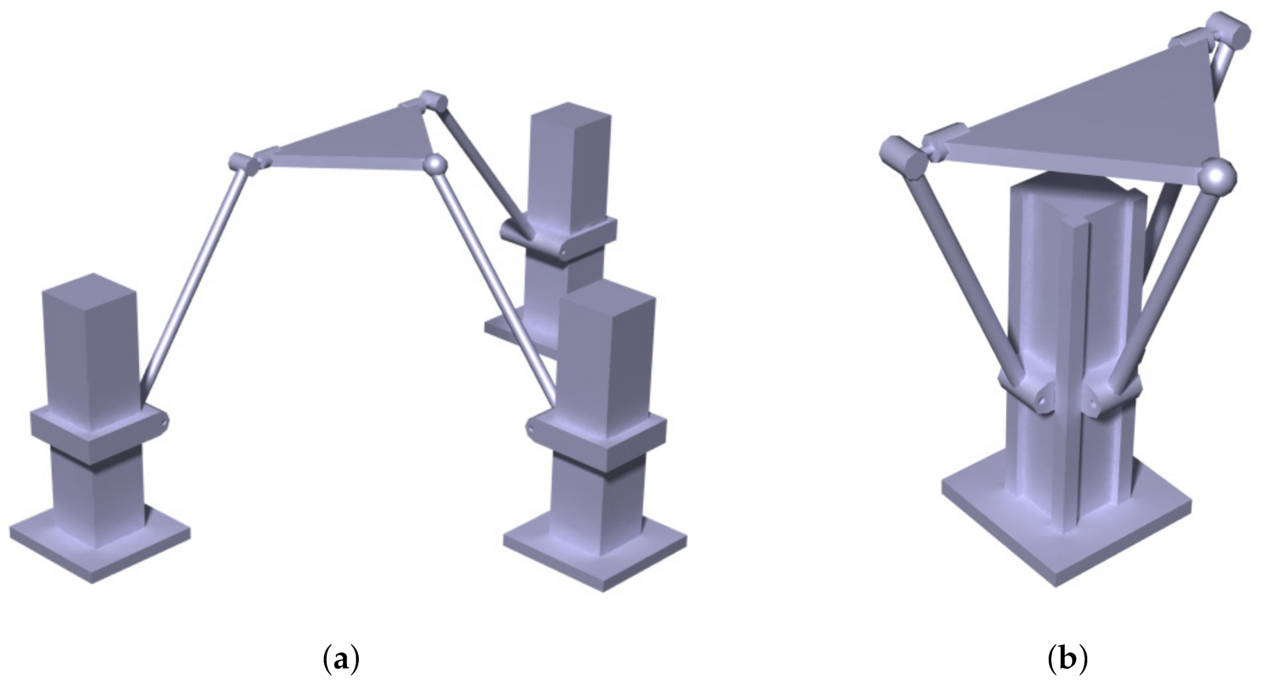
As we observe in 
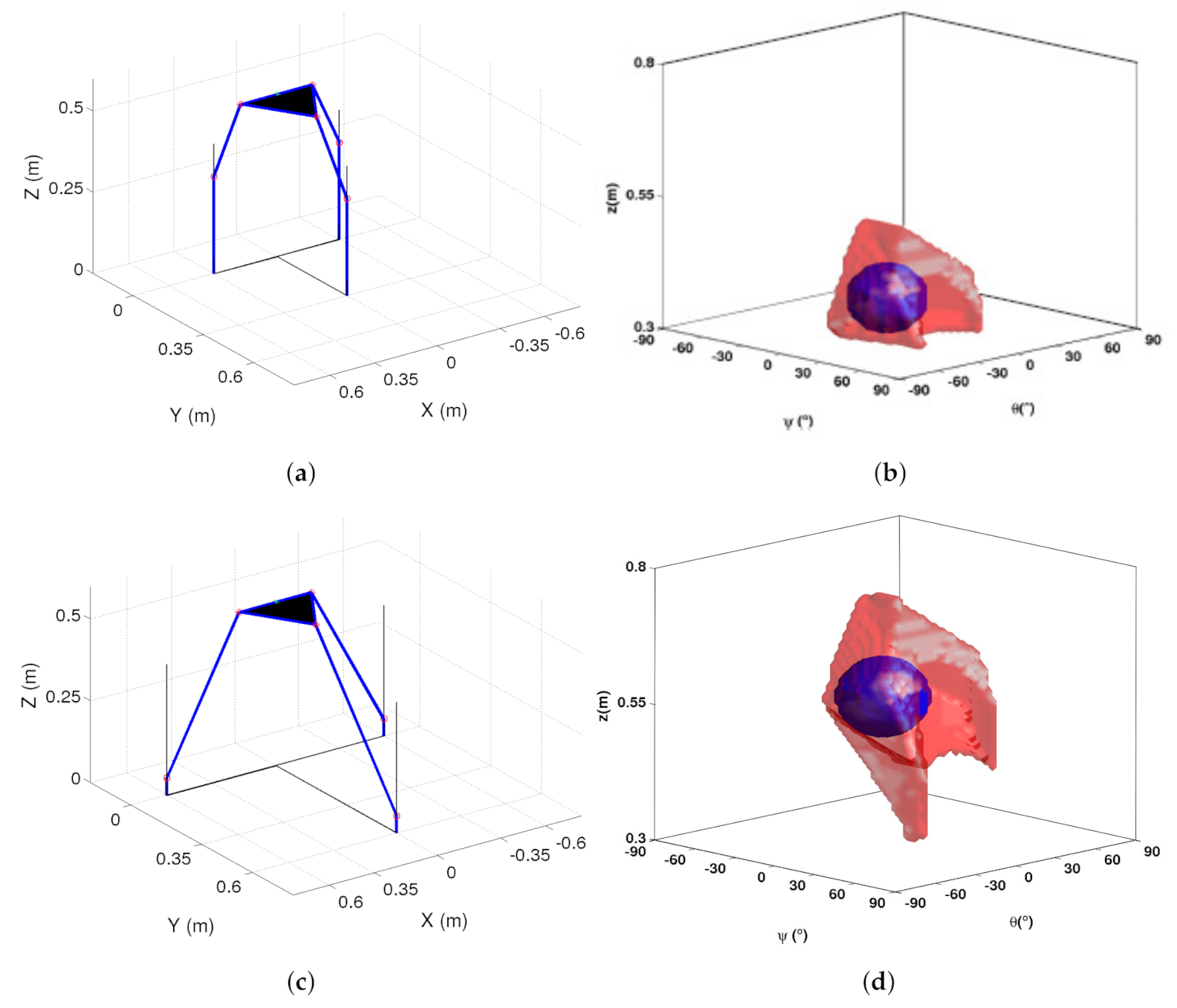
Figure 5, the 2PRU-1PRS manipulator can have two configurations depending on the relation between the value of the radius of the mobile platform and the radius of the fixed platform. Figure 5a shows the configuration with the radius of the mobile platform smaller than the radius of the fixed platform, while Figure 5b shows the configuration with the radius of the mobile platform bigger than the fixed one. In this work, we study the first configuration; thus, the StudyVariables have to fulfill the condition H > R.
Since H, L and R form a triangle, they must satisfy the triangle in equality. That is, the sum of the values of the radius of the mobile platform and the length of the limbs has to be greater than the radius of the fixed platform, H < L + R. Thus, there are two conditions that we have to apply when defining the suitable GP combinations:
i
The radius of the mobile platform is smaller than the radius of the fixed platform, R < H;
ii
The sum of the radius of the mobile platform and the length of the limbs is larger than the radius of the fixed platform R + L > H.
By applying these restrictions, we obtain only 529 suitable GP combinations. The number of GP combinations to check has thus been reduced by 47.1% from the 1000 initial GP combinations to the 529 suitable GP combinations.
Similarly, we obtain the S t u d y P o i n t s . The workspace represents the poses that the the end-effector of the manipulator can reach. In this case, since our outputs are two rotations and one translation, the points in the workspace will be defined by the translation along Z-axis and the rotations about X and Y axes. Thus, StudyPoints is the set of points which lie in the three-dimensional space bounded by the ranges given by Table 2. We discretize each axis into 60 points, obtaining a cubic grid of size 60 × 60 × 60. Therefore, the total number of S t u d y P o i n t s is 216,000. We also define the ranges of the linear guides (LG) and the spherical joint (SJ) as seen in Table 3.
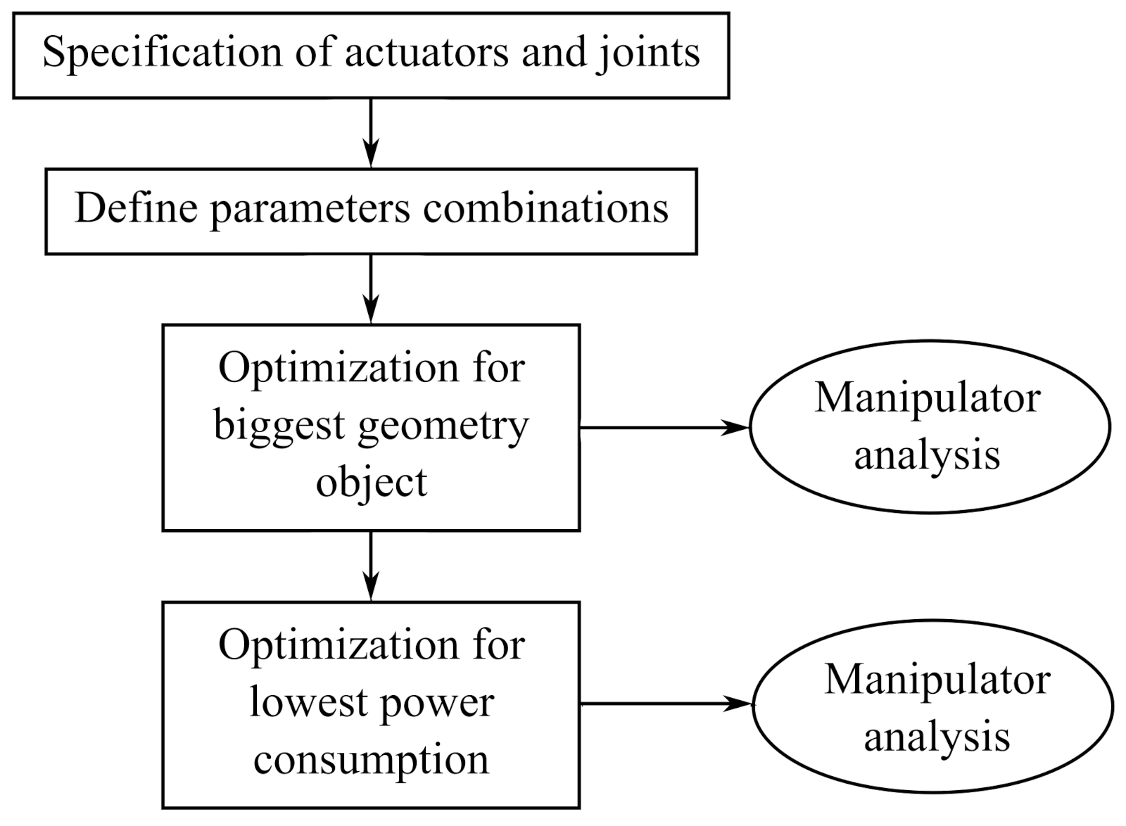
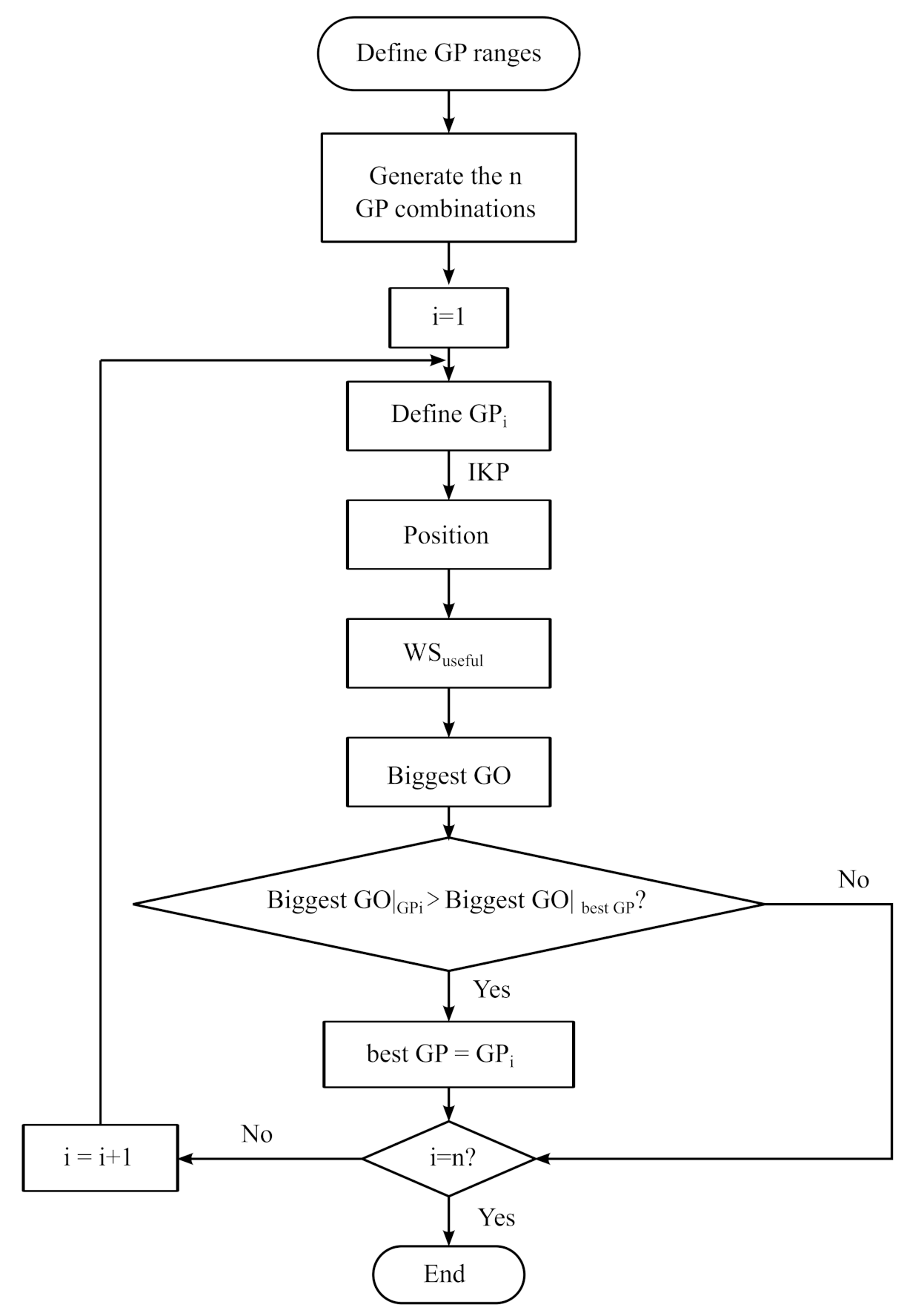
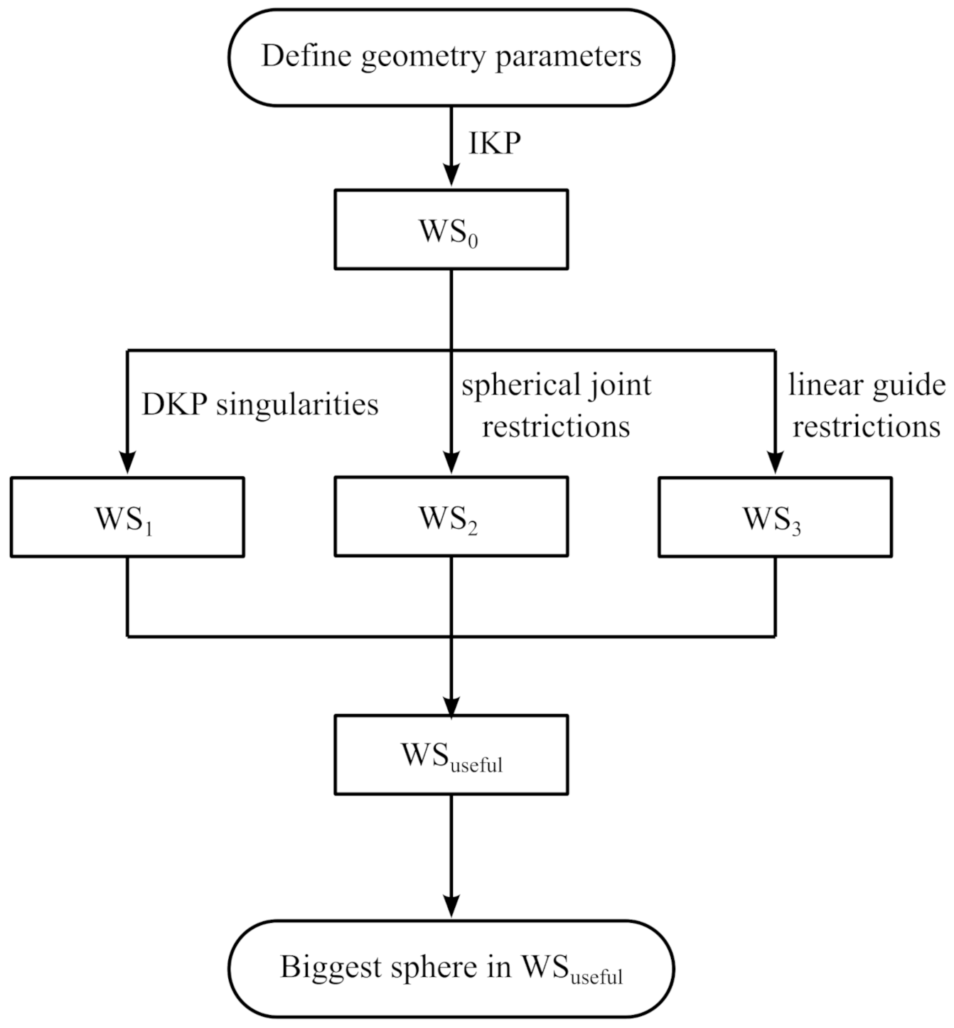
In order to have an idea of the regularity of the useful workspace and be able to determine which solution is the best one, we obtained the useful workspace and the biggest sphere in it for each suitable GP combination. The useful workspace denotes the region of the workspace free of singularities of the inverse and direct kinematic problems and where, additionally, the physical restrictions of the spherical joint and the linear guides are fulfilled. As already mentioned, we will also study the regularity of the useful workspace by obtaining the biggest sphere in it. Figure 6 shows the steps we will follow to obtain the useful workspace of the manipulator and the biggest sphere (S m a x ) in it for each GP combination.
For each GP combination, we first solve the inverse kinematic problem for all the candidate-poses for the workspace, and we obtain the value of the linear guides. If those solutions are imaginary, they are not possible solutions for our workspace. We define this workspace as W S 0 . We next check which points of W S 0 are in the region free of singularities and fulfill the restrictions of the spherical joint and the linear guides. The calculation of the inverse kinematic problem and the singularities is presented in Herrero et al. [24].
When a manipulator is in a singularity of the inverse kinematic problem, the end-effector is stuck and it cannot move in the direction of the 3DOF. Mathematically, singularities related to the inverse kinematic problem appear when the determinant of the Jacobian matrix J q is null: Equation (9), as explained by Merlet [3], Macho et al. [26], Altuzarra et al. [27] and Gosselin and Angeles [28]. In practice, these singularities appear on the boundary of the workspace. We obtain the singularities of the 2PRU-1PRS PM.
| J q | = 0 Singularity   of   the   inverse   kinematic   problem
When the manipulator reaches a singularity of the direct kinematics problem, it will be able to move in an infinitesimal way without changing the value of the inputs. In other words, some degrees of freedom become uncontrollable. Mathematically, this happens when the determinant of the Jacobian matrix J x is null: Equation (10) [3]. We define | J x | 0 as the Jacobian matrix determinant of the direct kinematic problem in the initial mobile platform position. For a workspace free of singularities of the direct kinematic problem, | J x | of all the points of the workspace must have the same sign. Thus, the Jacobian matrix determinant must have the same sign as | J x | 0 [26,27,28,29]. The set of points that fulfills this condition defines the W S 1 workspace.
| J x | = 0 Singularity   of   the   direct   kinematic   problem
The range of rotation of spherical joints is very limited. We have defined a range of [ 25 , 25 ] since it is one of the biggest ranges we can find in commercial spherical joints. W S 2 denotes the set of points of the W S 0 that fulfill the spherical joint restriction.
By solving the inverse kinematic problem, we obtain the values of the linear guides for all the StudyPoints. We checked if those values fulfill the limits of the real linear guides. Since in our case the linear guides have a displacement ( ρ i ) from 0 to 0.3 m, linear guides have to fulfill Equation (11):
ρ i [ ρ m i n , ρ m a x ]
where ρ m i n = 0 and ρ m a x = 0.3 .
Accordingly, we define the useful workspace as the set of points that fulfill all the previous conditions and obtain the biggest sphere that fits in each useful workspace.
Since StudyPoints are a uniform grid, we can define the “diameter of a sphere” in StudyPoints space to be number of points along the diameter.
We denote by S m a x the largest sphere from the obtained set. The best GP combination is the one that results in the useful workspace containing the S m a x . Note that we can have multiple useful workspace that contain the S m a x . In that case, the best GP combination is the one that results in the S m a x that can be placed in the most number of positions.
For these set ranges, S m a x has a radius of seven discretization points. Table 4 shows the GP combinations that result in the useful workspace containing the S m a x and the number of positions where it can be placed.
As we can observe, there are 15 GP combinations that result in a useful workspace containing the S m a x . For six of those combinations, the center of the S m a x can be placed in two different positions, while it can be placed in four different positions for the other nine. Thus, there are nine best GP combinations given by Table 5.
Figure 7 shows two of the best solutions and their useful workspace containing the S m a x placed in the first possible position. As we can observe, even if the biggest sphere is of the same size and it can be placed in the same number of places; the solution for the manipulator as well as the shape and position of the useful workspace can be very different.

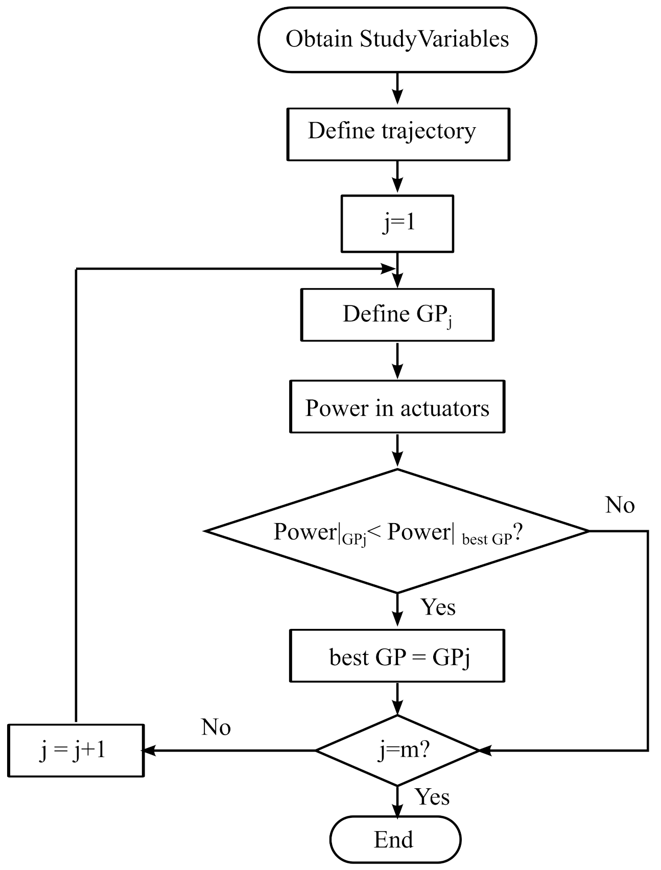
4.2. Minimize the Power Consumption

In this second algorithm, we optimize the suitable GP combinations for which the sphere contained in the useful workspace is at least 0.5·S m a x . The suitable GP combinations that fulfill this restriction are the StudyVariables that will be considered for the power consumption optimization. In our case there are 325 StudyVariables combinations in total.
We fix the radius of the limbs and the thickness of the mobile platform. Even if these two parameters affect power consumption, in this method we only optimize the StudyVariables obtained by solving the optimization of the workspace: The optimization variables in our case will continue being H, L and R. In case we wanted to optimize the thickness of the mobile platform and the radius of the legs, the procedure would be similar, but the computational cost would increase considerably. To solve the dynamics, we also have to define the density of each component of the manipulator. We consider the material of the mobile platform to be aluminum and the material of the limbs to be steel. We chose the radius of the limbs to be 0.005 m and the thickness of the mobile platform to be 0.004 m.
The motors are Maxon DC Motors, with graphite brushes and a maximum power of 150 Watt. We attach to them a Maxon Planetary GP 42 C with a reduction ratio of 15. The guides we use are IGUS toothed belt linear guides.
A GP combination is suitable in the optimization of the power consumption for a given trajectory when it fulfills all the restrictions of the linear guides, motors and the gear head. According to this, in order to be a suitable GP combination for the optimization of the power consumption for a given trajectory, a GP combination has to fulfill the following conditions:
i
The displacement of the linear guides has to be in their displacement range: 0 < ρ i < 0.3 m.
ii
The velocity of the linear guides has to be lower than their velocity limit: d ρ i < 5 m/s.
iii
The radial load in the linear guides has to be lower than the maximum radial load: F r a d i a l i < 300 N.
iv
The axial load in the linear guides has to be lower than the maximum belt tension: F a x i a l < 200 N.
v
The speed of the motors have to be lower than the maximum speed allowed: Speed m a x < 12,000 rpm. The expression that gives the speed of the motors is Equation (12):
S p e e d i = d ρ i R g e a r h e a d · 60 2 π · R e d u c t i o n R a t i o ( r . p . m )
where R g e a r h e a d is the radius of the gearhead and we obtain it by applying Equation (13).
R g e a r h e a d = D i s p l a c e m e n t R a t i o 2 π ( m )
vi
The power required by the motors has to be lower than the maximum power: Pow i < 150 W. We calculate the power that the motors consume by applying Equation (14).
P o w i = d ρ i · F a x i a l i ( W )
vii
The torque supported by the motors cannot exceed the maximal possible torque: T i < 0.177 Nm. We obtain the torque in the motors by solving Equation (15).
T i = m e a n ( F a x i a l i ) · R g e a r h e a d R e d u c t i o n R a t i o ( N · m )
We check these criteria for each StudyVariables and obtain the suitable GP combinations for the power optimization process. We calculate the total power consumption during the studied trajectory for each suitable GP combination. The power consumption of one motor over the trajectory is obtained by integrating the power required by the motor overtime, as shown in Equation (16). Equation (17) gives the expression of the total power consumption, which is the sum of the power consumption of the three actuators.
P o w e r C o n s u m p t i o n i = P o t i ( t ) d t ( W )
P o w e r C o n s u m p t i o n T = P o w e r C o n s u m p t i o n i ( W )
We define the best GP combination in terms of power consumption as the suitable GP combination that requires the lowest power consumption for the trajectory analysed. The power consumption depends on the trajectory of the mobile platform; thus, we have different solutions of best GP combination for different trajectories. These trajectories have to be chosen according to the desired application of the manipulator. In this work, we optimized the manipulator for the three harmonic trajectories given in Table 6: one rotation about X-axis, one rotation about Y-axis and one translation along Z-axis. We set the total time of the trajectory to be 4 seconds and discretize the trajectory into 500 points, with the time step being 0.008 s. We designate the frequency and the amplitude values to be the most commonly used for vehicle control vibration tests in Spain: frequency of 2.7 Hz and amplitude of 3 for the rotation trajectories and 3 mm for the translation.

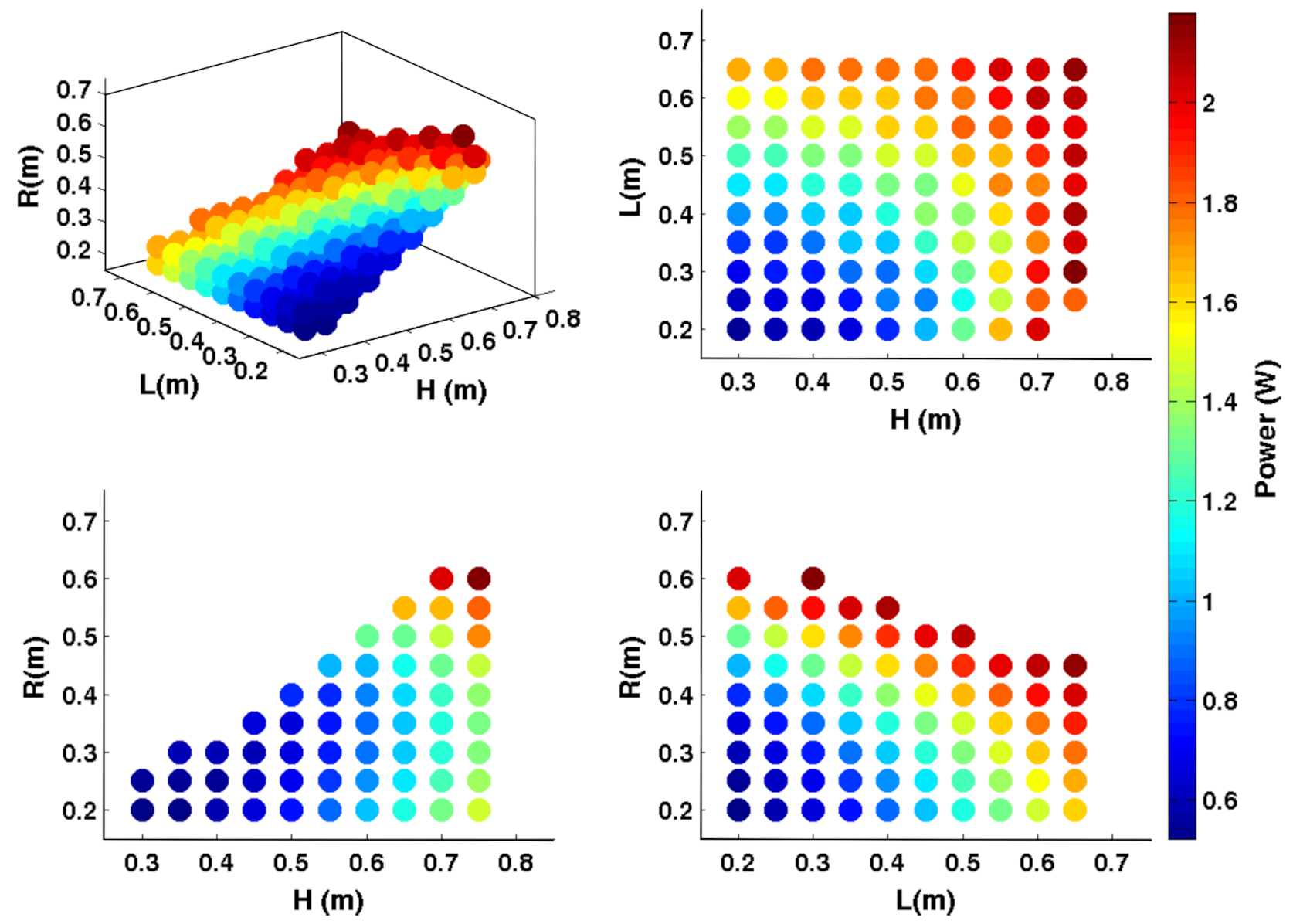
4.2.1. Translation along Z-Axis

We solve the inverse kinematic and dynamic problems for the translation along Z-axis and check that all the StudyVariables are suitable GP combinations in this case. We obtain the total power consumption for each suitable GP combination and observe that the GP combination that consumes the highest power is (H, L, R) = (0.75, 0.3, 0.6) m: it consumes a total power of 2.1812 W. For this trajectory, we have two best GP combinations: (H, L, R) = (0.35, 0.2, 0.2) m and (H, L, R) = (0.3, 0.2, 0.2) m. Both combinations consume a total power of 0.5224 W. Figure 8 shows the power consumption for each suitable GP combination.

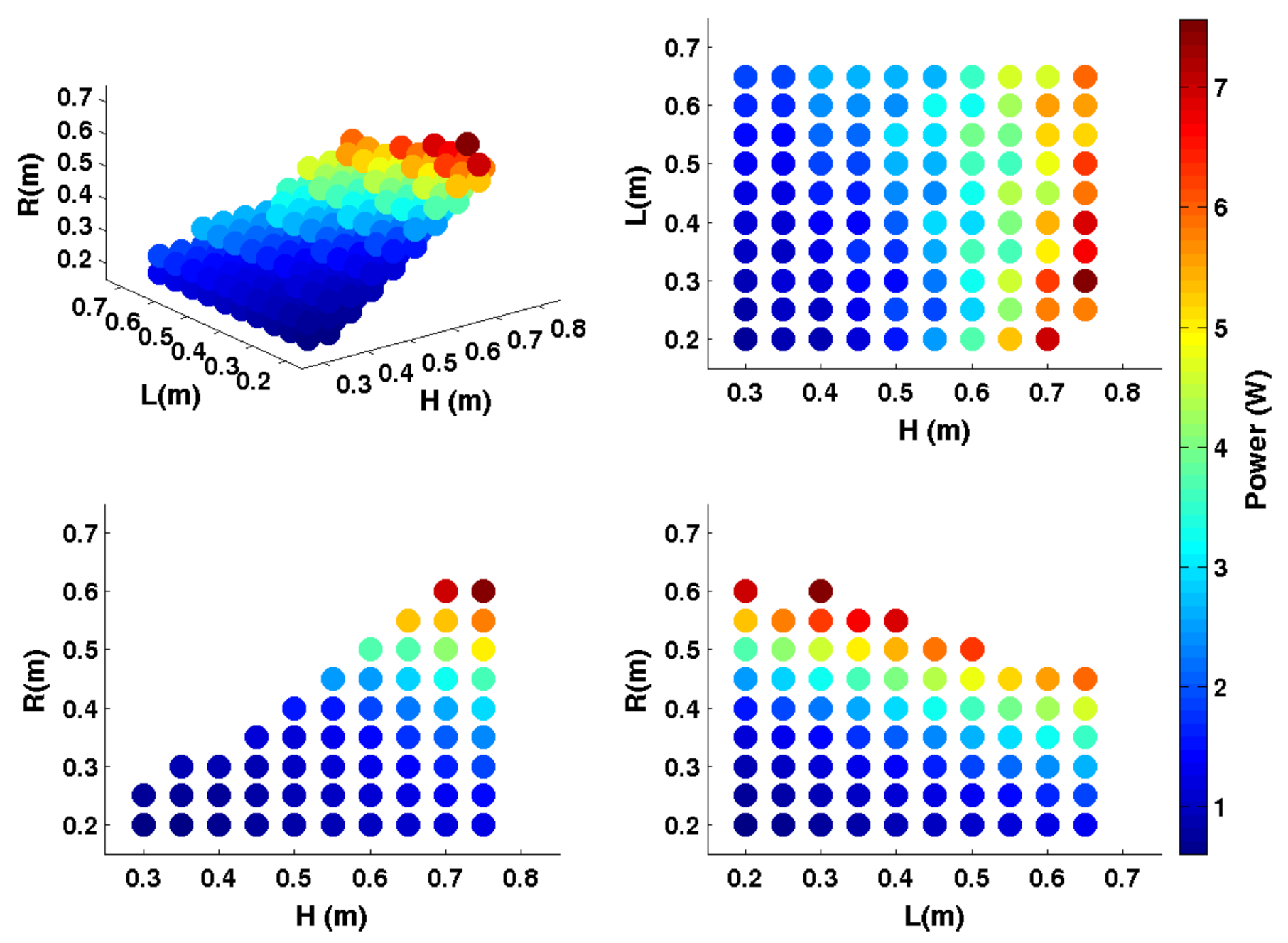
4.2.2. Rotation about X-Axis

We solve the inverse kinematic and dynamic problems for the StudyVariables. We observe that the 325 StudyVariables fulfill the requirements of the motors and the linear guides and they are, thus, suitable GP combinations. Figure 9 shows the total power consumption for all the suitable GP combinations for the rotation about X-axis. The GP combination (H, L, R) = (0.75, 0.3, 0.6) m is the combination that consumes the most for this trajectory: 7.5687 W. The lowest power consumption is 0.683 W and it corresponds to the GP combination (H, L, R) = (0.35, 0.2, 0.2) m. Thus, (H, L, R) = (0.35, 0.2, 0.2) m is the best GP combination for the rotation about X-axis.

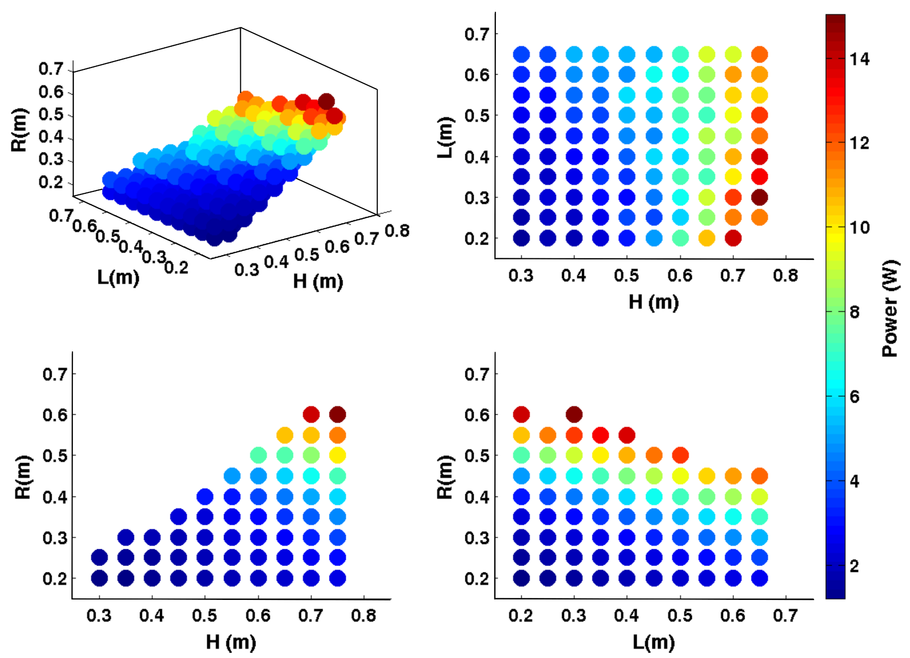
4.2.3. Rotation about Y-Axis

We checked if the StudyVariables fulfill the restrictions of the linear guides and motors and observed that all of them are suitable GP combinations. We obtained the total power consumption for all the suitable GP combinations during the harmonic trajectory about Y-axis, and it can be observed in Figure 10. In this case, the highest total power consumption is 15.0413 W, corresponding to the GP combination (H, L, R) = (0.75, 0.3, 0.3) m. The lowest total power consumption is 1.2133 W, the best GP combination for the rotation about Y-axis, (H, L, R) = (0.35, 0.2, 0.2) m.

5. Discussion

We have proposed two optimization methods based on grid search that consider the size and regularity of the workspace. The first one obtains the geometric parameters combination that results in the biggest and most regular workspace. The second method analyzes the geometric parameters combinations that result in an acceptable size of the workspace—even if it is not the biggest one—and find out which ones result in the lowest power consumption. The main advantages of these methods are their flexibility, the simplicity of the calculations and the visual results that allow us to compare the results easily.
We have applied the two methods to the particular case of the 2PRU-1PRS parallel manipulator. We now summarize briefly to aide interpreting the results obtained.
We applied the workspace optimization method to 1000 GP combinations and obtained the GP combinations that result in the biggest sphere in the useful workspace. The biggest sphere has a radius of seven discretization points. There are 15 GP combinations for which their useful workspace can house the biggest sphere. For six of those GP combinations, the biggest sphere can be placed in two positions, while the biggest sphere can be placed in four different positions in the useful workspace for the other nine. Thus, we obtained nine best GP combinations.
We define the StudyVariables of the power optimization method as the GP combinations that result in a useful workspace containing a sphere at least 0.5·S m a x . This provides us with 325 StudyVariables to analyse in the power optimization method. The best GP combination of this method is the one that results in the lowest power consumption.
The power consumption depends on the trajectory of the manipulator. We define three different harmonic trajectories to be studied: one rotation about the X-axis, one rotation about the Y-axis and one translation along the Z-axis. We observe that for the case of the rotations, the best GP combination is (H, L, R) = (0.35, 0.2, 0.2) m. For the translation along the Z-axis, we obtained two best combinations: (H, L, R) = (0.35, 0.2, 0.2) m and (H, L, R) = (0.3, 0.2, 0.2) m. Since (H, l, R) = (0.35, 0.2, 0.2) m is the optimal solution for the three trajectories, we define it as the best GP combination according to power consumption.

Author Contributions

Conceptualization, S.H. and C.P.; methodology, S.H.; software, S.H. and A.Z.; validation, S.H., C.P. and M.D.; formal analysis, S.H. and C.P.; investigation, S.H. and C.P.; data curation, S.H., M.D. and A.Z.; writing—original draft preparation, S.H.; writing—review and editing, C.P. and M.D.; supervision, C.P. All authors have read and agreed to the published version of the manuscript.

Funding

This research was funded by the Regional Government of the Basque Country (IT949-16) and the Science and Innovation Ministry of the Spanish Government (PID2019-105262RB-I00).

Acknowledgments

The authors wish to acknowledge the financial support received from the Science and Innovation Ministry of the Spanish Government (Project PID2019-105262RB-I00) and the Regional Government of the Basque Country (Project IT949-16).

Conflicts of Interest

The authors declare no conflict of interest.

Abbreviations

The following abbreviations are used in this manuscript:
LLimbs length
RMobile platform radius
HBase platform radius
tThickness of the mobile platform
sRadius of the cross-section of the limbs
ψ Rotation about X-axis
θ Rotation about Y-axis
PMParallel manipulator
DOFDegree of freedom
MPMobile platform
GPGeometric parameter
S m a x Biggest sphere in the useful workspace

References

  1. Hüsing, M.; Riedel, M.; Corves, B.; Nefzi, M. Development of tailor-made robots- from concept to realization for small and medium-sized enterprises. In Proceedings of the 13th World Congress in Mechanism and Mahcine Science, Guanajuato, Mexico, 19–23 June 2011. [Google Scholar]
  2. Modungwa, D.; Tlale, N.; Twala, B. Ttechnique applied in designoptimization of parallel manipulators. In Proceedings of the Robotics andMechatronics Conference of South Africa (ROBMECH), Gauteng, South Africa, 23–25 November 2011. [Google Scholar]
  3. Merlet, J.-P. Parallel Robots; Kluwer Academic: Dordrecht, The Netherlands, 2000. [Google Scholar]
  4. Merlet, J.-P. Design a parallel manipulator for a specificworkspace. Int. J. Robot. Res. 1997, 16, 545–556. [Google Scholar] [CrossRef]
  5. Laribi, M.; Romdhane, L.; Zeghloul, S. Analysis and dimensional systhesis of the delta robot for a prescribed workspace. Mech. Mach. Theory 2007, 42, 859–870. [Google Scholar] [CrossRef]
  6. Liu, X.-J.; Wang, J.; Oh, K.-K.; Kim, J. A new approach to the design of a delta robot with a desired workspace. J. Intell. Robot. Syst. 2004, 39, 209–225. [Google Scholar] [CrossRef]
  7. Huang, T.; Jiang, B.; Whitehouse, D. Determination of the carrriage stroke of 6-pss parallel manipulators having the specific orientation capability in a prescribed workspace. In Proceedings of the 2000 ICRA Millennium Conference, IEEE International Conference on Robotics and Automation, San Francisco, CA, USA, 24–28 April 2000; pp. 2382–2385. [Google Scholar]
  8. Xu, L.; Li, Q.; Zhang, N.; Chen, Q. Mobility, kinematic analysis, and dimensional optimization of new three-degrees-of-freedom parallel manipulator with actuation redundancy. J. Mech. Robot. 2017, 9, 041008. [Google Scholar] [CrossRef]
  9. Haouas, W.; Dahmouche, R.; Fort-Piat, N.L.; Laurent, G. A new seven degrees-of-freedom parallel robot with a foldable pltform. J. Mech. Robot. 2018, 10, 045001. [Google Scholar] [CrossRef] [Green Version]
  10. Pittens, K.; Podhorodeski, R. A family of stewart platforms with optimal dexterity. J. Robot. Syst. 1993, 10, 463–479. [Google Scholar] [CrossRef]
  11. Gosselin, C.-M.; Angeles, J. A global performance index for the kinematic optimization of robotic manipulators. J. Mech. Des. 1991, 113, 220–226. [Google Scholar] [CrossRef]
  12. Chakarov, D. Optimization sysnthesis of parallel manipulators with desired stiffness. J. Theor. Appl. Mech. 1998, 28. Available online: https://www.researchgate.net/publication/253854929_OPTIMIZATION_SYNTHESIS_OF_PARALLEL_MANIPULATORS_WITH_DESIRED_STIFFNESS (accessed on 17 August 2021).
  13. Kucuk, S. Dexterous workspace optimization for a new hybrid parallel robot manipulator. J. Mech. Robot. 2018, 10, 064503. [Google Scholar] [CrossRef]
  14. Babu, S.; Raju, V.; Ramji, K. Design for optimal performance of 3-RPS parallel manipulator using evolutionary algorithms. Trans. Can. Soc. Mech. Eng. 2013, 37, 135–155. [Google Scholar] [CrossRef]
  15. Hussain, S.; Jamwal, P.K.; Kapsalyamov, A.; Ghayesh, M.H. Numerical Framework and Design Optimization of an Intrinsically Compliant 3-DOF Parallel Robot. J. Comput. Inf. Sci. Eng. 2021, 21, 021008. [Google Scholar] [CrossRef]
  16. Xie, Z.; Xie, F.; Liu, X.-J.; Wang, J.; Shen, X. Parameter optimization for the driving system of a 5- degrees-of-freedom parallel machining robot with planar kinematic chains. J. Mech. Robot. 2019, 11, 041003. [Google Scholar] [CrossRef]
  17. Wu, G.; Caro, S.; Kepler, S.B.a.J. Dynamic modeling and design optimization of a 3-dof spherical parallel manipulator. Robot. Auton. Syst. 2014, 62, 1377–1386. [Google Scholar] [CrossRef] [Green Version]
  18. Hu, B.; Shi, D.; Xie, T.; Hu, B.; Ye, N. Kinematically identical manipulators derivation for the 2-rpu+upr parallel manipulator and their constraint performance comparison. J. Mech. Robot. 2020, 11, 041003. [Google Scholar] [CrossRef]
  19. Roozing, W.; Li, Z.; Caldwell, D.G.; Tsagarakis, N.G. Design optimisation and control of compliant actuation arrangements in articulated robots for improved energy efficiency. IEEE Robot. Autom. Lett. 2016, 1, 1110–1117. [Google Scholar] [CrossRef]
  20. Roozing, W.; Ren, Z.; Tsagarakis, N.G. An efficient leg with series–parallel and biarticular compliant actuation: Design optimization, modeling, and control of the eLeg. Int. J. Robot. Res. 2021, 40, 37–54. [Google Scholar] [CrossRef] [Green Version]
  21. Russo, M.; Raimondi, L.; Dong, X.; Axinte, D.; Kell, J. Task-oriented optimal dimensional synthesis of robotic manipulators with limited mobility. Robot.-Comput. Manuf. 2021, 69, 102096. [Google Scholar] [CrossRef]
  22. Liu, X.-J.; Wang, J. A new methodology for optimal kinematic design of parallel manipulators. Mech. Mach. Theory 2007, 42, 1210–1224. [Google Scholar] [CrossRef]
  23. Herrero, S.; Mannheim, T.; Prause, I.; Pinto, C.; Corves, B.; Altuzarra, O. Enhancing the Useful Workspace of a Reconfigurable Parallel Manipulator by Grasp Point Optimization. Robot. Comput. Integr. Manuf. 2015, 31, 51–60. [Google Scholar] [CrossRef]
  24. Herrero, S.; Pinto, C.; Altuzarra, O.; Diez, M. Analysis of the 2PRU-1PRS 3DOF parallel manipulator: Kinematics, singularities and dynamics. Robot. Comput. Integr. Manuf. 2018, 51, 63–72. [Google Scholar] [CrossRef]
  25. Herrero, S.; Pinto, C.; Diez, M.; Corral, J. Analytical procedure based on the matrix structural method for the analysis of the stiffness of the 2PRU–1PRS parallel manipulator. Robotica 2019, 1–14. [Google Scholar] [CrossRef]
  26. Macho, E.; Amezua, O.A.E.; Hernandez, A. Obtaining configuration space and singularity maps for parallel manipulators. Mech. Mach. Theory 2009, 44, 2110–2125. [Google Scholar] [CrossRef]
  27. Altuzarra, O.; Pinto, C.; Avilés, R.; Hernandez, A. A practical procedure to analyze singular configurations in closed kinematic chains. IEEE Trans. Robot. 2004, 20, 929–940. [Google Scholar] [CrossRef]
  28. Gosselin, C.; Angeles, J. Singularity analysis of closed-loop kinematic chains. IEEE Trans. Robot. Autom. 1990, 6, 281–290. [Google Scholar] [CrossRef]
  29. Haidong, L.; Gosselin, C.-M.; Richard, M.-J. Determination of the maximal singularity-free zones in the six-dimensional workspace of the general Gough-Stewart platform. Mech. Mach. Theory 2007, 42, 497–511. [Google Scholar]
Figure 1. Optimization methodology.
Applsci 11 07770 g001
Figure 2. Optimization of GP to maximize the geometric object in the workspace.
Applsci 11 07770 g002
Figure 3. Optimization of GP to minimize the power consumption.
Applsci 11 07770 g003
Figure 4. Sketch of the manipulator.
Applsci 11 07770 g004
Figure 5. Possible configurations: (a) R < H; (b) R > H.
Applsci 11 07770 g005
Figure 6. Steps to obtain the useful workspace and the S m a x in it.
Applsci 11 07770 g006
Figure 7. Two optimal GP: (a) sketch of (H, L, R) = (0.35, 0.25, 0.2) m; (b) useful workspace and S m a x for (H, L, R) = (0.35, 0.25, 0.2) m; (c) sketch of (H, L, R) = (0.6, 0.6, 0.2) m; (d) useful workspace and S m a x for (H, L, R) = (0.6, 0.6, 0.2) m.
Applsci 11 07770 g007
Figure 8. Power in the actuators for all the suitable and best GP for translation about Z-axis.
Applsci 11 07770 g008
Figure 9. Power consumption for all the suitable GP for the rotation about X-axis.
Applsci 11 07770 g009
Figure 10. Power consumption for all the suitable GP for the rotation about Y-axis.
Applsci 11 07770 g010
Table 1. GP ranges for the optimization process.
DescriptionValue
H (m)Radius of the fixed platform(0.3, 0.75)
L (m)Length of the limbs(0.2, 0.65)
R (m)Radius of the mobile platform(0.2, 0.65)
Table 2. Output limits.
DescriptionValue
ψ ( )Rotation about X-axis(−90, 90)
θ ( )Rotation about Y-axis(−90, 90)
z (m)Translation along Z-axis(0.3, 0.8)
Table 3. Physical restrictions.
DescriptionValue
LG (m)Range of the linear guide(0, 0.3)
SJ ( )Range of the spherical joint(−25, 25)
Table 4. GP combinations for biggest sphere in the workspace.
H (m)L (m)R (m)Sphere Positions
10.350.250.24
20.40.30.24
30.450.350.24
40.450.40.22
50.50.40.22
60.50.450.24
70.550.450.22
80.550.50.24
90.550.550.24
100.60.550.24
110.60.60.24
120.60.650.22
130.650.550.352
140.650.60.354
150.70.60.252
Table 5. Best GP combinations for S m a x in maximum number of positions in the useful workspace.
H (m)L (m)R (m)
10.350.250.2
20.40.30.2
30.450.350.2
40.50.450.2
50.550.50.2
60.550.550.2
70.60.550.2
80.60.60.2
90.650.60.35
Table 6. Harmonic trajectories definition.
traject ( t ) = C + A · sin ( ω t )
CA f = ω / ( 2 · π ) t
X- and Y-axes0 3 2.7 Hz4 s
Z-axis 0.5 m 0.003 m 2.7 Hz4 s
Publisher’s Note: MDPI stays neutral with regard to jurisdictional claims in published maps and institutional affiliations.

