Article

Sensorless Control for DC–DC Boost Converter via Generalized Parameter Estimation-Based Observer

1
School of Automation, Nanjing University of Information Science and Technology, No. 219, Ningliu Road, Nanjing 210044, China
2
Instituto Politécnico Nacional-CITEDI Av. Instituto Politécnico Nacional No. 1310 Col. Nueva Tijuana, Tijuana 22435, BC, Mexico
*
Author to whom correspondence should be addressed.
Appl. Sci. 2021, 11(16), 7761; https://doi.org/10.3390/app11167761
Submission received: 28 July 2021 / Revised: 18 August 2021 / Accepted: 19 August 2021 / Published: 23 August 2021
(This article belongs to the Special Issue Power Converters: Modeling, Control, and Applications)

Abstract

:
The full-information state feedback controller is usually used for regulating the output voltage of converters. Sufficient sensors should be adopted to measure all of the states. However, the extensive use of current sensors not only increases the cost of the overall system, but also affects the reliability. In this paper, the sensorless control problem of DC–DC boost converters is addressed to avoid the need for the current sensor. First, a PI passivity-based control (PI-PBC) is proposed to stabilize this converter. The main feature of this design is that the exponential convergence of the system is guaranteed. Afterward, a generalized parameter estimation-based observer (GPEBO) is presented to estimate the inductor current with the finite-time convergence (FTC). By adding this estimate in the above PI-PBC, a sensorless controller is developed. Thanks to this FTC, the exponential convergence of an overall closed-loop system is ensured. Finally, the simulation and experimental results are given to assess the performance of the proposed controller.

1. Introduction

DC–DC boost converters are widely used in new energy systems, which can increase the voltage between the source and load ports [1,2,3,4]. To show the advantage of this, four main application cases are clearly introduced, which are shown in Figure 1. First, the boost converter can be adopted in battery-powered devices [5], which is revealed in Figure 1a. It is known that the output voltage of a high-energy battery varies greatly under the conditions of high current charge and discharge. In particular, when the power of the battery is low, its output voltage will be very low. However, some battery-powered devices require a relatively constant voltage in the above cases. At this point, the boost converter can be placed between the battery and the electrical equipment. In that case, the voltage of the battery can be increased to the desired value required by the devices and maintained around this voltage. A practical example is an air conditioning device in a marine auxiliary system, where the power supply of the air conditioning compressor and ventilator should be from the storage battery in the case of the failure of the external power supply. It is noted that the variation range of the battery voltage is very wide. In this case, the ideal solution for the power supply is to implement a boost converter to raise the battery voltage to 510 V. Then, the inverter and AC motor are employed to drive the air conditioning compressor and ventilator.
The control system of the traditional inner feedback wound induction motor contains a diode rectifier, thyristor current type inverter and a large direct current reactor. This will result in a low power factor and high harmonics. If the boost converter is added to the output port of the rectifier and the turn-off device is use to constitute the inverter, the DC reactor can be eliminated to reduce harmonics and improve the power factor of the inverter power supply [6,7]. The whole system circuit is simple and the technology is mature, which is shown in Figure 1b. The overall cost is much lower than that of the medium voltage frequency conversion of the stator and the total energy consumption is also less than that of the direct frequency conversion.
The boost converter also plays an important role in wind generator systems [8]. In order to better control the three-phase current of the generator, its three-phase windings can be separated to connect the boost converter, which is shown in Figure 1c. The output sides of three boost converters are connected in parallel. In this situation, the control problem of the generator does not need to consider the synchronization problem with the power grid. The output current and the speed of the generator can be regulated by controlling the boost converters. Further, it is easy to achieve the peak power tracking of the power generation system and obtain the maximum output power under a certain wind speed. This scheme is more efficient than others, and causes an increase in total annual power generation.
The use of boost in the energy harvest of solar cells is presented in Figure 1d. For this system, each solar cell module connects to a boost converter to increase the voltage, which is conducive to the balanced output of each battery module [9,10,11]. Moreover, when adding the maximum power search control, each group of modules can run at the best current operating point. As long as each output voltage is set at the same value, all the outputs can be connected together with the storage pool or inverter.
Based on the above statement, it should be pointed out that the boost converter has a great effect on the power system. Therefore, its control performance directly affects the stability and reliability of the overall system. Not surprisingly, many methods have been proposed to stabilize boost converters, such as sliding mode control [12], boundary control [13], robust control [14], passivity-based control [15], H control [16] and backstepping control [17]. It is noted that the abovementioned results focus on the full-information feedback control scheme. That is, it should be supposed that all of the states can be measured. However, the current sensors and their processing circuits cause extra hardware costs, delays and noise in the system. They can also harm the reliability of the power system. Therefore, current sensorless control techniques can provide cost-effective and reliable solutions for various boost converter applications.
In References [18,19], based on the immersion and invariance (I&I) technique, a sensorless controller, which combines a nonlinear controller and state observer, is developed to stabilize boost converters. It is noted that the exponential stability of a closed-loop system is ensured. It is reported in [20,21,22,23,24] that the well-known Luenberger observer is designed to reconstruct the current under continuous conduction mode (CCM) or discontinuous conduction mode (DCM). By combining this with some advanced controllers, sensorless controllers are derived. A discrete current observer proposed in [25] is used to estimate the states of the converters. A unified current observer devised in [26] is proposed for six kinds of converters. By incorporating the progressive control method, the sensorless control algorithm can be designed. In addition, the small-signal injection technique [27], extended Kalman filter method (EKF) [28,29], high gain observer [30] and sliding mode observer [31,32,33] are developed to estimate the current of boost converters. For the interleaved boost converter, authors have proposed a sensorless current balance controller on the basis of the phase current estimate [34]. By designing a first-order observer for estimating the voltage derivative, the current estimate is obtained [35]. After that, an output feedback controller is proposed for boost converters by means of combining the PD controller and current observer. In [36], the authors design a sensorless control scheme for boost converters from the view of the frequency domain. In [37], an adaptive nonlinear observer is devised to estimate the current and unknown parameter of boost PFC AC/DC converters. It is noted that the abovementioned works contain two main problems. First, all of the previous controllers only ensure the asymptotic/exponential convergence of the state observer. Second, the proposed results center on a particular topology of converters.
It should be noted that the finite-time convergence (FTC) will contribute to improving the transient and robustness. Therefore, for the simpler case of a buck converter described by a linear system, authors have proposed different kinds of finite-time observers to reconstruct the knowledge of the current [38,39,40]. However, there are no studies about designing the finite-time state observer for the complicated case of a class of converters expressed by a nonlinear system. Being aware of these two problems, a generalized parameter estimation-based observer (GPEBO) proposed in [41] is adopted to estimate the inductor current of a boost converter with FTC. In addition, a PI-PBC is designed to stabilize it. The main contributions of this paper are as follows.
  • A PI-PBC is proposed to stabilize a DC–DC boost converter with exponential stability.
  • A GPEBO is constructed to estimate the inductor current. It is noted that the FTC of this observer is ensured and a very weak persistence of excitation (PE) condition is needed. Moreover, this result can be easily extended to a large class of converters.
  • The experimental results are given to assess the performance of the proposed sensorless control law.
The remainder of this paper is as follows. The model of this system is described in Section 2. Subsequently, in Section 3, a sensorless control law is developed by combining PI-PBC and GPEBO. The simulation and experimental results are shown in Section 4 and Section 5, respectively. The conclusion is given in Section 6.

2. System Model and Problem Formation

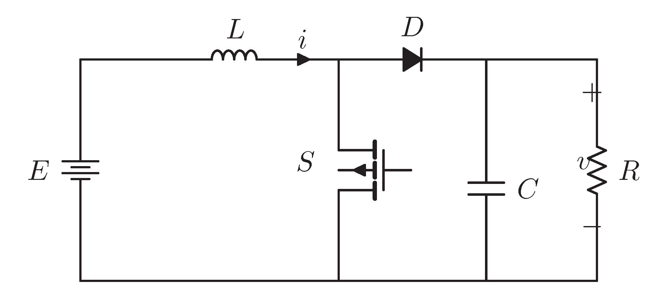
2.1. Model of DC–DC Boost Converter with CPL

The topology shown in Figure 2 corresponds to a DC–DC boost converter. It is assumed that this converter works in continuous conduction mode (CCM). Based on the state-space averaging method proposed in [42,43], its averaged model is expressed as
L i ˙ = ( 1 d ) v + E , C v ˙ = ( 1 d ) i v R ,
where i R is the inductor current, v R the output voltage, R resistance, E the input voltage, L inductor, C capacitance, d [ 0 , 1 ] duty ratio. The equilibrium set is described as
E : = i R , v R i v 2 R E = 0 .
Remark 1.
As stated in Section 2.1, it is assumed that the boost converter works in CCM. Hence, the present work does not consider discontinuous conduction mode (DCM). The model of the converter under DCM is different from Equation (1), which is shown in [44].

2.2. Problem Formulation

The main objective of this paper is to propose a sensorless control law for the boost converter. It is assumed that the induct current i is not measured. For the given v , the control law with the following features is designed.
F1.
The estimate of the state i can converge to its real value with the FTC. That is,
i ^ ( t ) = i ( t ) , t > t c
F2.
( i , v ) is an exponentially stable equilibrium of the closed-loop system. Namely, for all initial conditions, the following claim is achieved with the estimate i ^ .
lim v ( t ) = v ,
with all signals bounded.

3. Sensorless Controller Design

In this section, a sensorless control law is designed for the DC–DC boost converter. The design procedure can be divided into three steps.
  • It is supposed that the state i is measured. The full-information PI-PBC is designed.
  • A GPEBO is devised to estimate the current with FTC.
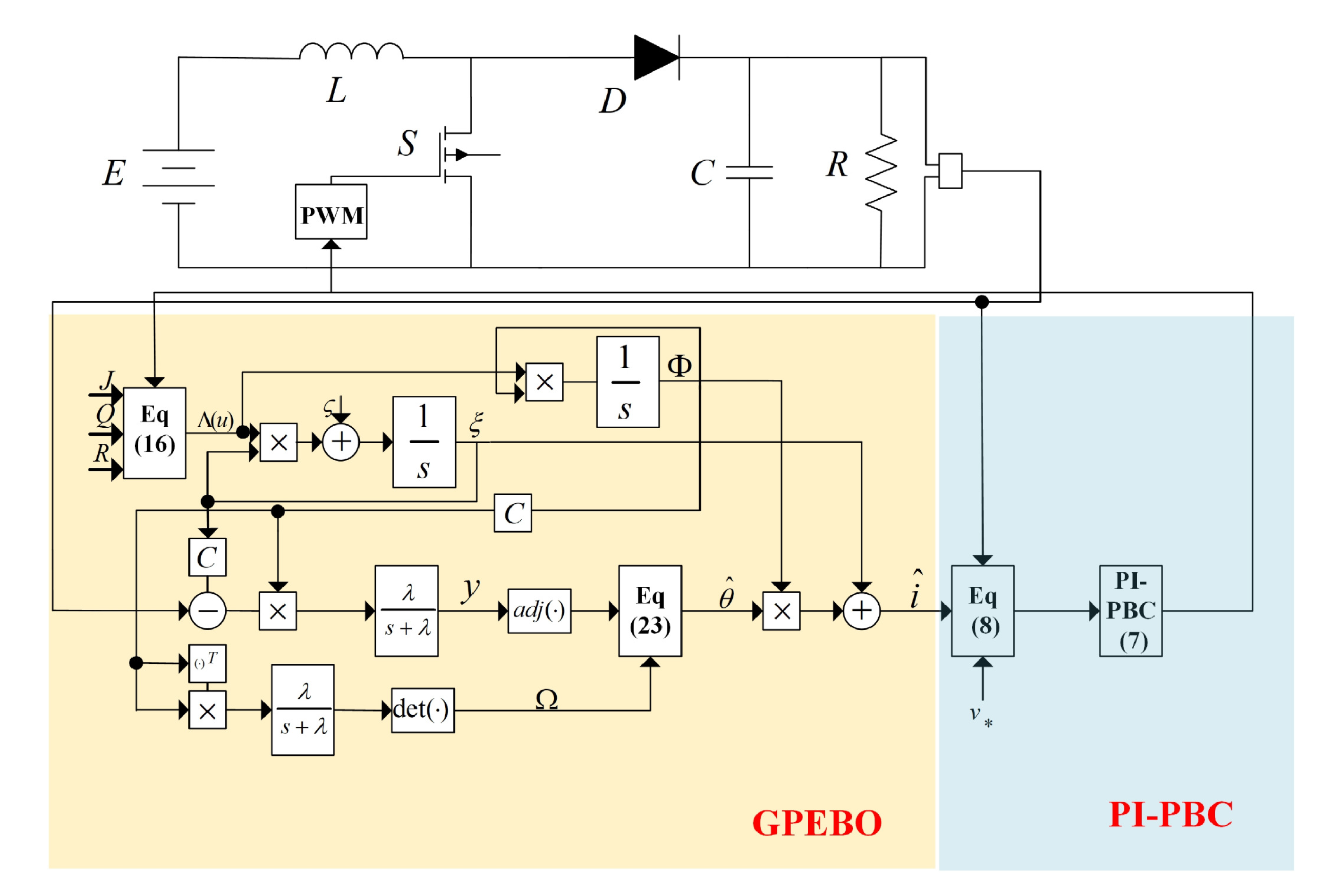
  • By combining the PI-PBC and GPEBO, a sensorless control scheme is achieved.
The system in Equation (1) can be rewritten in the port-controlled Hamiltonian form
x ˙ = ( J u R ) Q x + ζ ,
where u = 1 d ,
x = L i C v , J = 0 1 1 0 , Q = 1 L 0 0 1 C , R = 0 0 0 1 R , ζ = E 0 .
Moreover, the desired dynamics for the system (Equation (5)) are given by
x ˙ = ( J u R ) Q x + ζ ,
where x E .

3.1. PI-PBC Design

First, the PI-PBC is proposed to stabilize the boost converter. Here, we assume that x 1 is measured.
Proposition 1.
A PI-PBC is designed as
x ˙ c = y ˜ , u = k p y ˜ k i x c
with the passive output
y ˜ = x ˜ T Q g ,
where g = J Q x . For all x E , the equilibrium
( x , x c ) = ( x , 1 k i u )
is globally exponentially stable with the following condition
ε < max 2 | g | k i Q , k p k i , R + k p | g | 2 > ε b b T 4 | g | 2 | Q | 2 + k i | g | 2 ,
where ε is a free constant, | g | 2 : = g g T , | Q | 2 : = Q Q T .
Proof. 
First, for convenience, g = J Q x is defined. To obtain the error dynamics, subtracting Equation (6) from Equation (5) gives
x ˜ ˙ = ( J u R ) Q x ˜ + u ˜ g y ˜ = x ˜ T Q g .
In addition, the PI-PBC (Equation (7)) can be rewritten as the error form
x ˜ ˙ c = x ˜ T g , u ˜ = k p x ˜ T g k i x ˜ c .
Defining the energy function
W = 1 2 x ˜ T Q x ˜ + k i 2 x ˜ c T x ˜ c ,
the closed-loop system combining Equation (10) with Equation (11) can be expressed as
x ˜ ˙ x ˜ ˙ c = J u R a g T g 0 W ,
where R a = R + k p g g T . Next, the exponential stability of the closed-loop system (12) should be proved. Towards this end, the following Lyapunov function is chosen.
V = W + ε k i x ˜ c g T x ˜ ,
which can be also expressed as
V = 1 2 Q x ˜ T k i x ˜ c T W 1 Q ε 2 g ε 2 g T 1 k i M Q x ˜ k i x ˜ c W .
Differentiating the function V along the trajectory (Equation (12)) with respect to time gives
V ˙ = x ˜ T R a x ˜ + ε k i x ˜ c g T ( J u R a ) Q x ˜ g k i x c + ε k i x ˜ T g g T x ˜ = x ˜ T R + ( k p ε k i ) g g T x ˜ ε k i 2 g T g x ˜ c T x ˜ c + ε k i g T ( J u R a ) x ˜ x ˜ c = Q x ˜ T k i x ˜ c R + ( k p ε k i ) g g T Q Q T ε b 2 Q ε b T 2 Q ε g T g N Q x ˜ k i x ˜ c = T W N W ,
where b T = g T ( J u R a ) . Hence, the condition M > 0 should be satisfied to ensure that the function V is a Lyapunov function. Moreover, the closed-loop system is exponentially stable as long as N > 0 . The sufficient condition is constructed as follows.
M > 0 ε < 2 | g | k i Q , N > 0 k p k i > ε R a > ε b b T 4 Q Q T g g T + k i g g T
When the above condition is satisfied, one has
V ˙ α V ,
where α = 2 λ min ( N ) λ min ( M ) . It is concluded that the closed-loop system is exponentially stable. □
Remark 2.
It is observed in [45] that the authors have proposed a PI-PBC to stabilize a large class of converters. However, it is noted that the closed-loop system is just asymptotically stable. One contribution of this paper is to extend this work to obtain exponential stability. This has been proved in Proposition 1.

3.2. GPEBO Design

The state x 2 is measured. To pose the observer design problem, we define a matrix C = [ 0 1 ] T such that the vector
y m = C x ,
is available for measurement.
To streamline the presentation of the result, we define the matrix
Λ ( u ) : = ( J u R ) Q ,
and make the following interval excitation assumption on a scalar signal Δ , which is defined below.
Assumption 1.
Fix a small constant μ ( 0 , 1 ) and a positive number γ. There is a time t c ( 0 , ) such that
0 t c Δ 2 ( τ ) d τ 1 γ ln ( 1 μ ) .
A GPEBO is designed to estimate the unmeasured state x 1 . The main idea of this technique is to transform the estimation problem of the state to observe the parameter.
Proposition 2.
Consider the system (5) with the measurable output y m (15). Define the GPEBO via
ξ ˙ = Λ ( u ) ξ + ζ
Φ ˙ = Λ ( u ) Φ , Φ ( 0 ) = I n
Y ˙ = λ Y + λ Φ C ( C ξ y m )
Ω ˙ = λ Ω + λ Φ C C Φ
ω ˙ = γ Δ 2 ω , ω ( 0 ) = 1
θ ^ ˙ = γ Δ ( Y Δ θ ^ ) ,
with λ > 0 , γ > 0 , free tuning parameters and
Y = a d j { Ω } Y , Δ = det { Ω } ,
where a d j { · } is the adjunct matrix. The state estimate
x ^ = ξ + Φ θ ^ FCT
where we introduced the vector
θ ^ FCT : = 1 1 ω c θ ^ ω c θ ^ ( 0 )
and ω c is defined via the clipping function
ω c = ω i f ω 1 μ , 1 μ i f ω > 1 μ .
ensures that, for all initial conditions ( ξ ( 0 ) , Y ( 0 ) , Ω ( 0 ) , θ ^ ( 0 ) ) R 2 × R 2 × R 2 × 2 × R 2 , we have that
x ^ ( t ) = x ( t ) , t > t c
with all signals bounded provided Δ verifies the above assumption.
Proof. 
Define the signal e : = x ξ . From Equations (5) and (18), one obtains the linear time-varying (LTV) system
e ˙ = A ( t ) e ,
where we have defined A ( t ) : = Λ ( u ( t ) ) . The state transition matrix of this LTV system satisfies Equation (19) and, consequently,
e : = Φ θ ,
where the initial condition e ( 0 ) = : θ is treated as an unknown constant vector. Using the definition of e we obtain
x = ξ + Φ θ .
Next, our task is to estimate the parameter θ so that we can reconstruct the state x using Equation (28). Towards this end, we use the output measurements of Equation (15) to obtain
y m = C x = C ξ + C Φ θ ,
which we can write as an LRE
y m C ξ = C Φ θ .
Following the DREM procedure, we carry out the next operations
Φ C ( y m C ξ ) = Φ C C Φ θ ( Φ C × ( 29 ) )
λ p + λ [ Φ C ( y m C ξ ) ] = λ p + λ [ Φ C C Φ ] θ ( λ p + λ [ · ] )
Y = Ω θ ( ( 20 ) , ( 21 ) )
adj { Ω } Y = adj { Ω } Ω θ ( adj { Ω } × )
Y = Δ θ ( ( 24 ) ) .
where p : = d d t , and to obtain the last identity, we use the fact that for any (possibly singular) n × n matrix M we have adj { M } M = det { M } I n . Adding the latter equation in Equation (23) yields the error dynamics
θ ˜ ˙ = γ Δ 2 θ ˜ ,
where θ ˜ : = θ ^ θ . Since Δ is a scalar, the solution of the latter equation is given by
θ ˜ = e γ 0 t Δ 2 ( s ) d s θ ˜ ( 0 ) , t 0 .
Now, notice that the solution of Equation (22) is
w ( t ) = e γ 0 t Δ 2 ( s ) d s .
The key observation is that, using the equation above in Equation (36), and rearranging terms, we obtain that
[ 1 w ( t ) ] θ = θ ^ ( t ) w ( t ) θ ^ ( 0 ) .
Finally, observe that w is a non-increasing function and, under the interval excitation, we have that
w c ( t ) = w ( t ) < 1 , t t c ,
The proof of state estimation convergence is completed, noting that the latter implies that
1 1 ω c ( t ) θ ^ ( t ) ω c ( t ) θ ^ ( 0 ) = θ , t t c ,
that, in view of Equations (25) and (28), implies Equation (27).
We proceed now to prove that all signals of the GPEBO are bounded. First, notice that Equation (18) is a copy of the converter dynamics in Equation (5). Therefore, ξ is bounded. To prove the boundedness of Φ , consider the quadratic function U ( Φ ) = 1 2 t r { Φ L Φ } whose derivative, along the trajectories of Equation (19), is
U ˙ = i = 1 n Φ i L Λ ( u ) Φ i = i = 1 n Φ i L R L Φ i c U ,
where t r { · } , denotes the trace, Φ i R 2 is the i-th column of the matrix Φ and c > 0 . Now, from Equation (21), we can see that boundedness of Φ implies boundedness of Ω . Finally, the fact that Y is bounded follows from the fact that Y = Ω θ . This completes the proof. □

3.3. Observer-Based PI-PBC

In this section, we propose our sensorless PI-PBC, which is obtained by combining the PI-PBC of Proposition 1 with the state observer reported in the previous subsection.
Proposition 3.
Consider the system in Equation (5) with the measurable outputs of Equation (15) in a closed loop with the PI-PBC of Proposition 1, where the state x 1 is replaced by an estimate x ^ 1 generated via the FCT GPEBO of Proposition 2.
Then, for all initial conditions of the plant and the controller ( x ( 0 ) , x c ( 0 ) ) R 2 × R and all initial conditions of the observer ( ξ ( 0 ) , Y ( 0 ) , Ω ( 0 ) , θ ^ ( 0 ) ) R 2 × R 2 × R 2 × 2 × R 2 , the trajectories of the closed-loop system are bounded and satisfy Equation (4).
Proof. 
First, notice that the output signal of Equation (8), evaluated with x ^ instead of x, may be written as
( x ^ x ) T g = [ x x + Φ ( θ ^ FCT θ ) ] T g       = y ˜ + ( θ ^ FCT θ ) T Φ T g .
Consequently, the PI-PBC (Equation (7)) takes the form
x ˙ c = y ˜ + ( θ ^ FCT θ ) T Φ T g u ˜ = k p y ˜ k i x ˜ c k p ( θ ^ FCT θ ) T Φ T g .
Adding the control signal u ˜ above in the system dynamics of Equation (10) yields
x ˜ ˙ = J u R Q x ˜ g [ k p y ˜ + k i x ˜ c + k p ( θ ^ FCT θ ) T Φ T g ] = : F x ( x , x c ) g k p ( θ ^ FCT θ ) T Φ T g ,
where F x ( x , x c ) corresponds to the system in a closed loop with the full-state measurable input signal u ˜ .
Proposition 1 ensures that ( x , x c ) is a globally exponentially stable (GES) equilibrium of the unperturbed system. Now, as shown in Proposition 2, The assumption ensures that θ ^ FCT ( t ) = θ for all t t c . Invoking the absence of finite escape times and the aforementioned GES property allows us to conclude that Equation (4) holds globally. □
Remark 3.
In this paper, the GPEBO is just designed for a boost converter. However, this technique can be extended to a large class of power converters described by port controlled Hamiltonian systems shown in [45].

4. Simulation Results

In this section, to assess the performance of the designed PI-PBC with GPEBO, related simulation research is conducted by using the software Matlab. The circuit parameters are given in Table 1. The structure of the proposed sensorless controller is shown in Figure 3. First, the tracking performance is verified by considering several step changes in x 2 . Next, the robustness against the parameter perturbations is investigated. Finally, the phase portrait is given to show the global convergence.

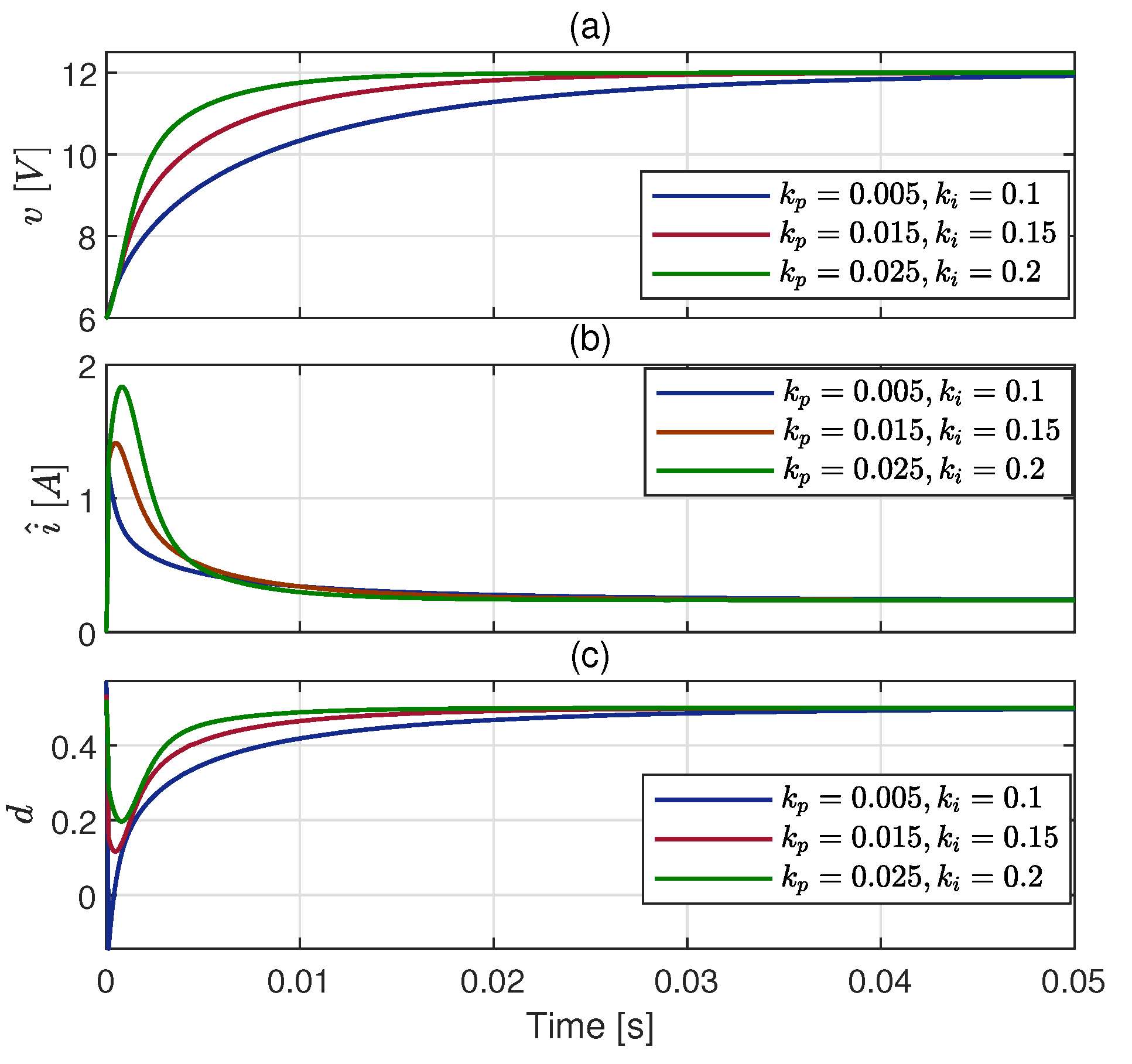
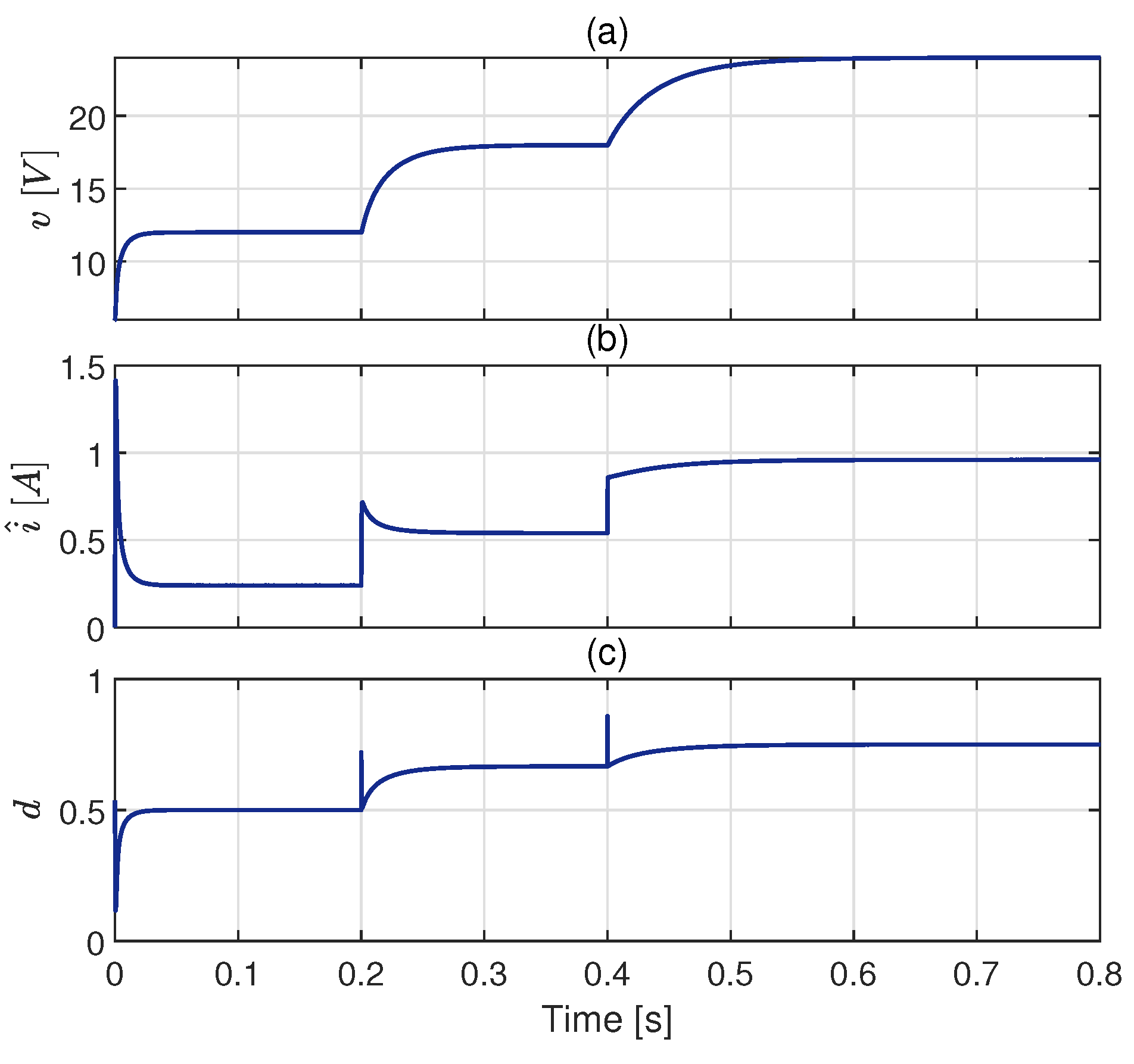
4.1. Scenario 1: Tracking Performance Test

The first scenario tests the tracking performance of the presented control scheme. The transient of boost converter under the PI-PBC with GPEBO is shown in Figure 4, which contains the traces of output voltage v, inductor current i and control input u. γ = 10,000, λ = 1000 , μ = 1 × 10 6 are set. It is seen that bigger gains obtain a better transient. Afterward, the step change in x 2 is considered. The nominal value of x 2 is 12 V . After 0.2 s , it is changed to 18 V . Similarly, the reference is set to be 24 V after 0.4 s . The simulation result is revealed in Figure 5 with the selection of k p = 0.015 , k i = 0.15 , which satisfies the condition of Equation (9). By observing this figure, one can see that the output voltage can converge to the desired values. Moreover, the estimated current also nicely approaches the real value. This can be seen by the result of the following estimation error.

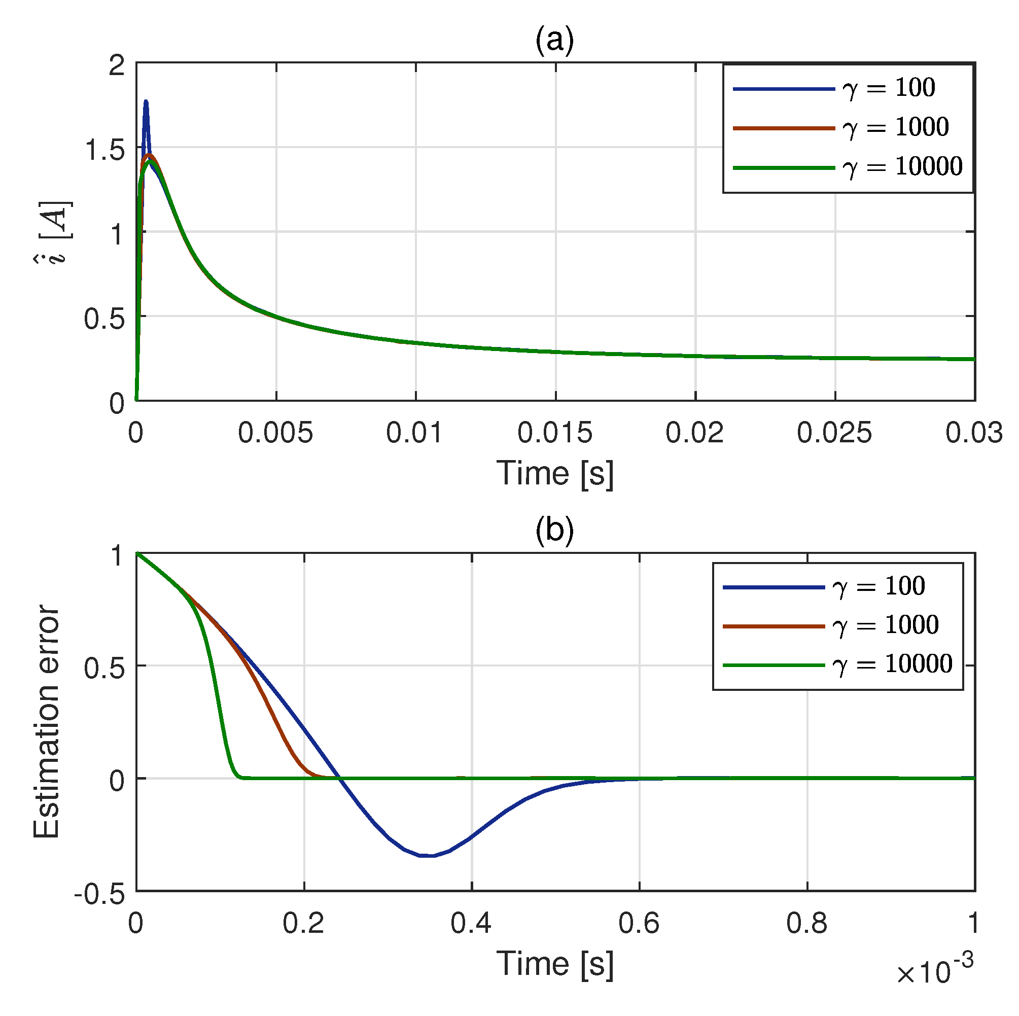
4.2. Scenario 2: GPEBO Performance Test

The performance of GPEBO is tested in this scenario. k p = 0.015 , k i = 0.15 , μ = 1 × 10 6 . By selecting a different observer gain γ , the convergence result of GPEBO is revealed, as shown in Figure 6. One can observe that the larger γ results in a quicker convergence rate. Interestingly, the initial amplitude of the estimated current does not increase with the rise in the gain. The reason is that the control gain is fixed during the GPEBO performance test. In this case, the real curve of the current is confirmed. Hence, the larger observer gain only allows the estimate of the current to converge to the real value more quickly. Instead, the smaller γ may result in this convergence process becoming slower, which may provide a bigger initial amplitude of the estimated current. This fact is clearly shown in the figure.

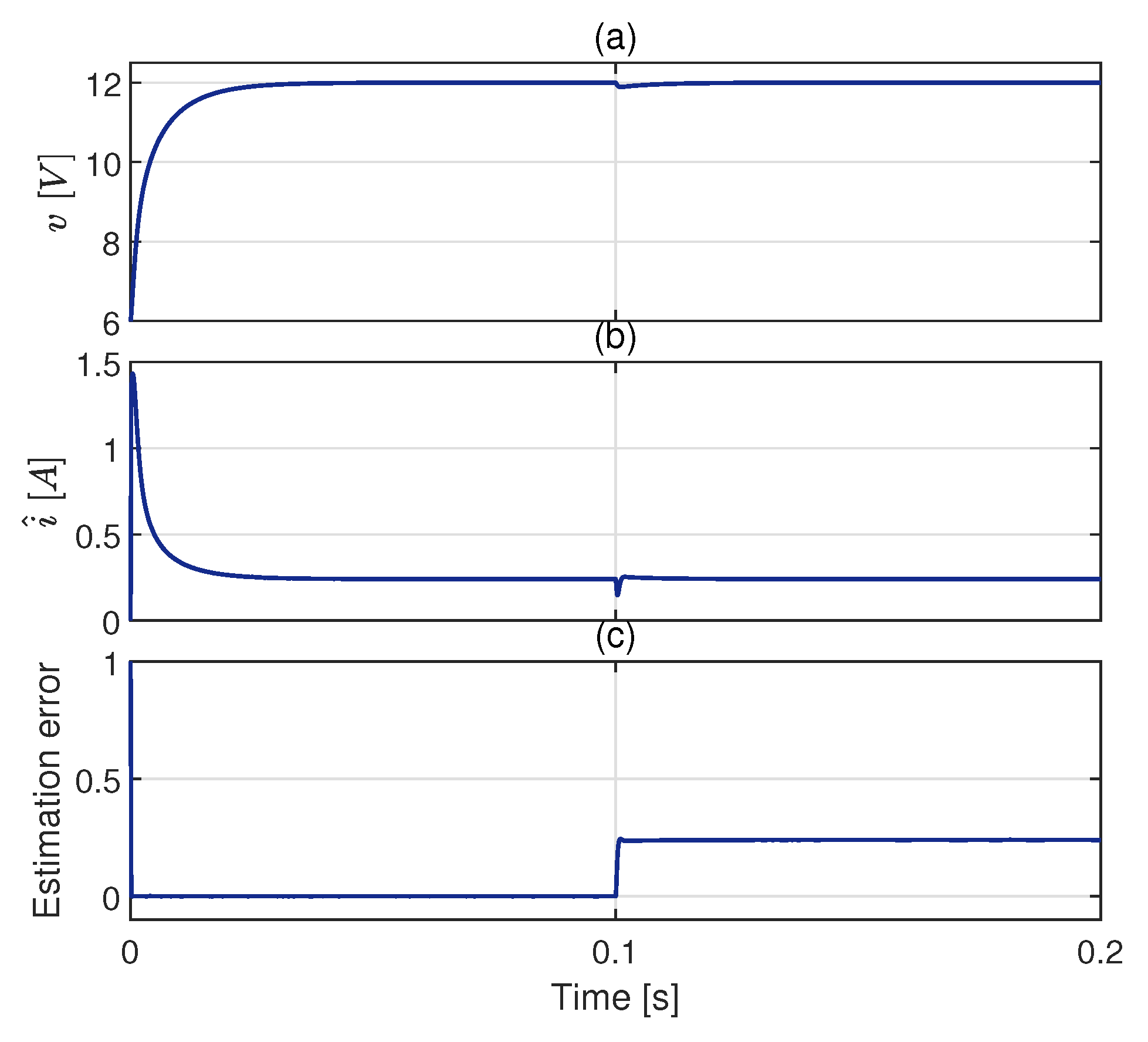
4.3. Scenario 3: Robustness Performance Test

The robustness performance is considered in scenario 3. To this end, the parameter perturbation of the resistance R is introduced. It varies from 100 Ω to 50 Ω at 0.1 s . γ = 10,000, λ = 1000 , k p = 0.015 , k i = 0.15 , μ = 1 × 10 6 . It is seen in Figure 7 that although the estimate i ^ has the steady state error, the proposed controller can eliminate the influence of the variation in the resistance in the closed-loop system. Indeed, the output voltage stays around the desired value of 12 V .

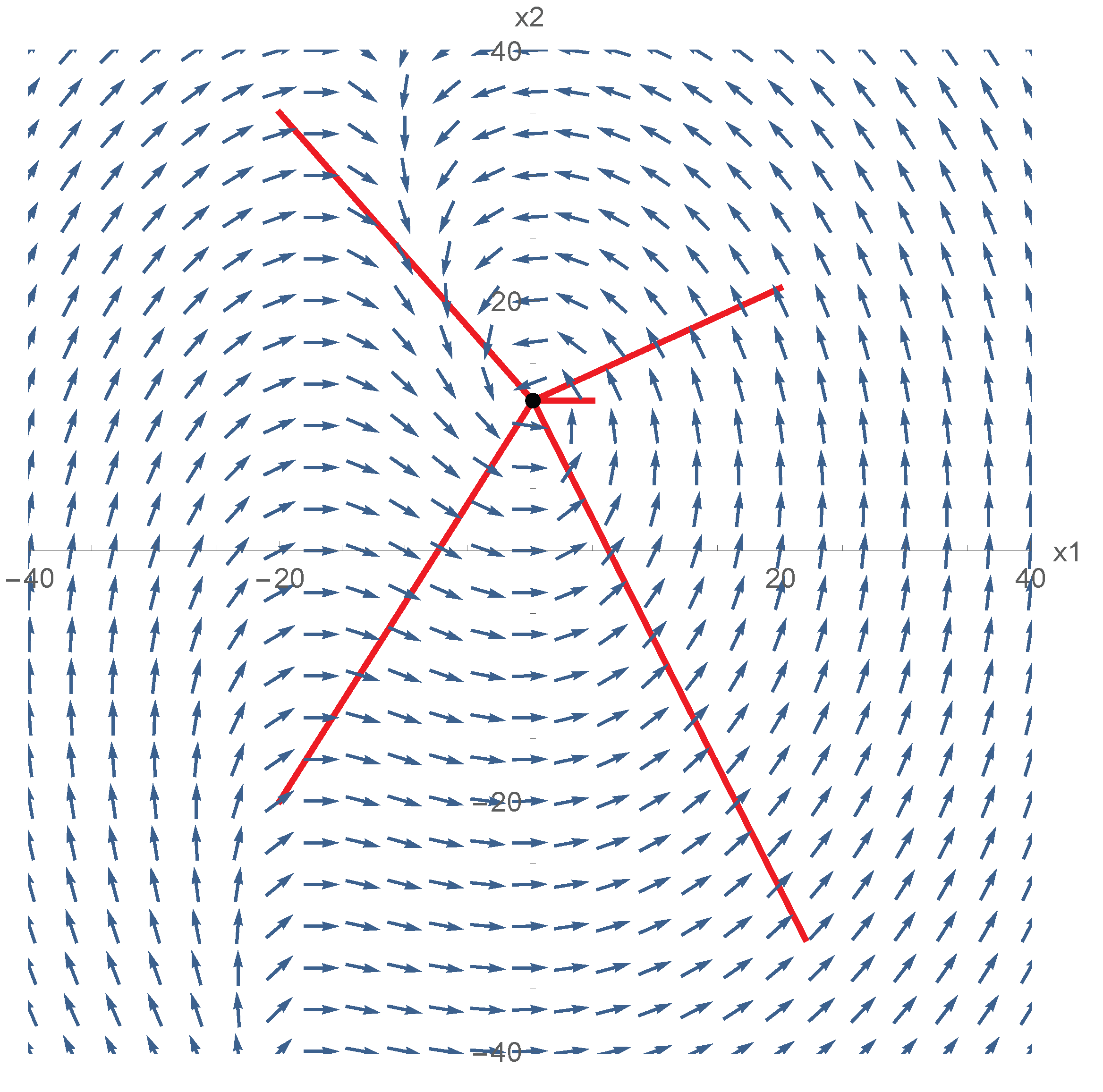
4.4. Scenario 4: Phase Portrait

To show the global convergence of a closed-loop system, the phase portrait is provided in Figure 8. It is assumed that the current i is estimated exactly. It is seen from the vector field that the initial conditions from the whole phase plane can converge to the equilibrium.

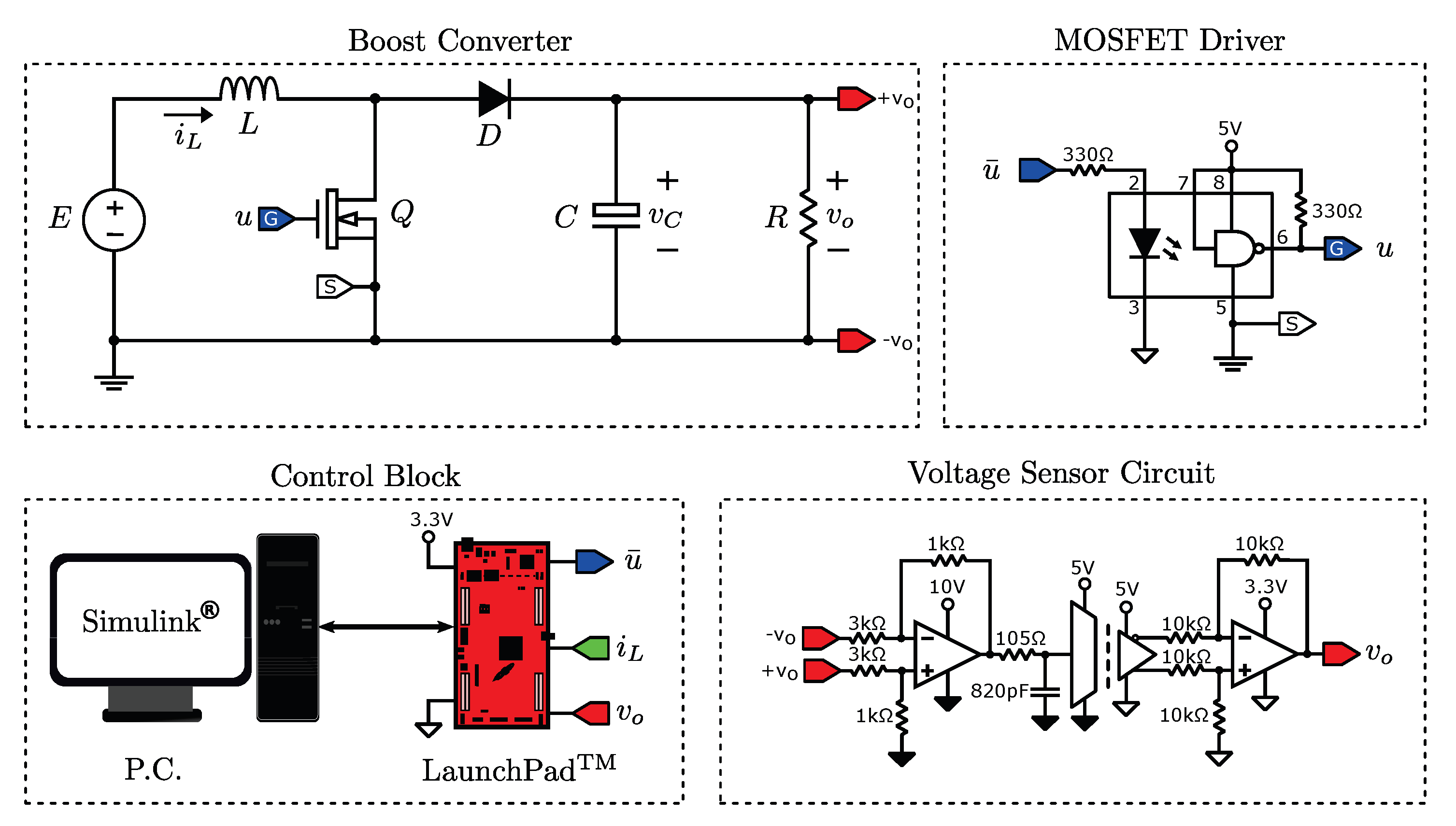
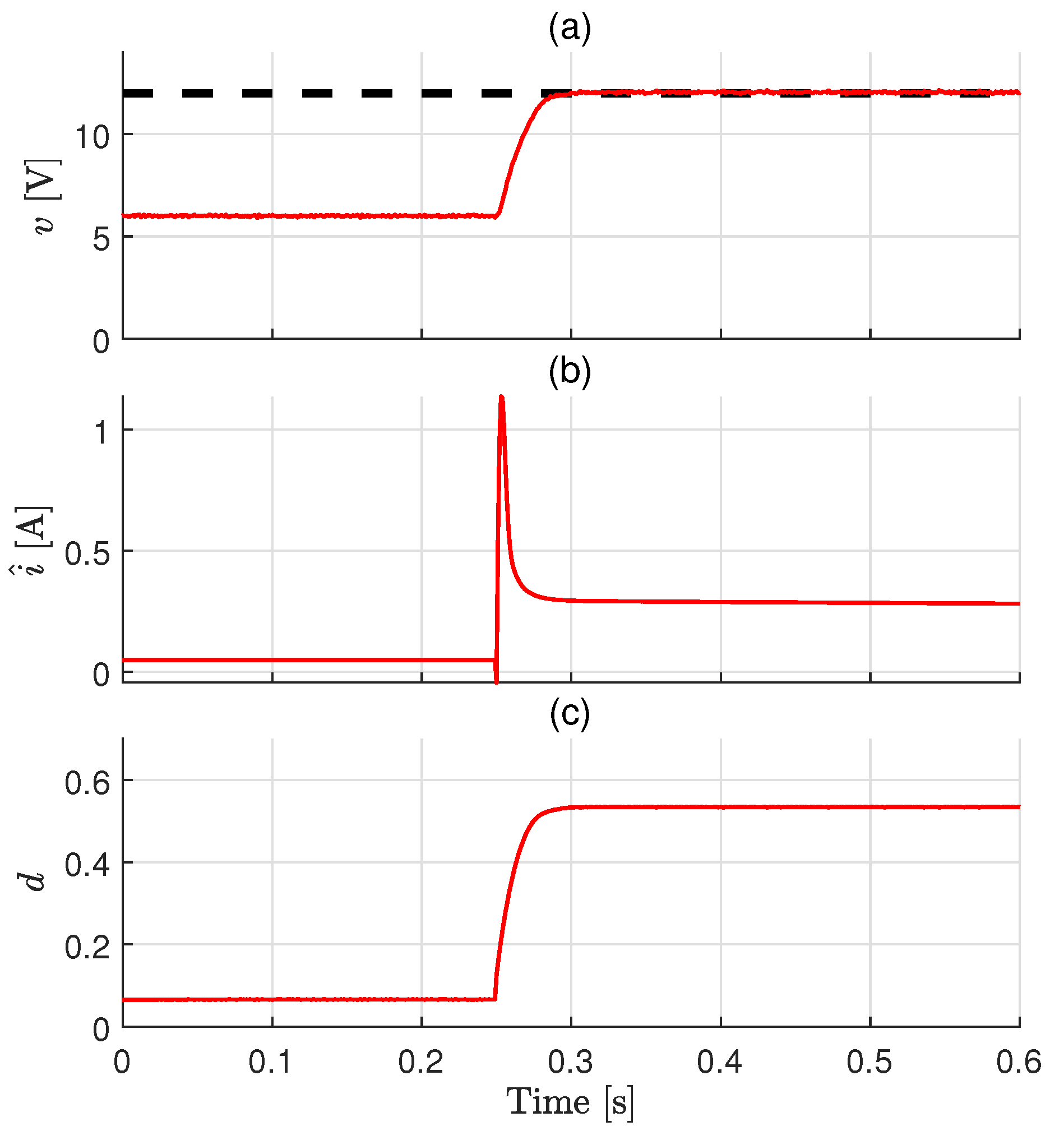
5. Experimental Result

The controllers are implemented in the TMS320F28379D digital signal processor (DSP) using the low-cost C2000 Delfino LaunchPad, which are produced by Texas Instruments in Dallas, TX, USA. Simulink is linked to Code Composer Studio to embed and implement the controller. Simulink generates C code and a real-time executable that is downloaded to the LaunchPad. Serial communication is used between Simulink and the LaunchPad to monitor and obtain the experimental results of the average control signal, d, and the output voltage signal, v.
The experimental platform is implemented using a logic level IRLZ44N N-channel MOSFET from infineon in Neubiberg, Germany and an STPS10L60 Schottky diode from STMicroelectronics in Dallas, TX, USA. The 6N137 optocoupler, which is from Fairchild in Silicon Valley, CA, USA, is used as the MOSFET driver. Two TLV237 operational amplifiers and one ISO224 isolated operational amplifier, which are produced by Texas Instruments in Dallas, TX, USA. are implemented to condition the output voltage vo in order to be measured by the DSP. The schematic diagram of the experimental platform is shown in Figure 9.
The parameters are chosen as k p = 0.025 , k i = 0.07 , γ = 10,000, λ = 1000 , μ = 1 × 10 6 . The experimental result is shown in Figure 10. It is observed that the designed controller will drive the output voltage to the desired value. Moreover, the estimate of the inductor current satisfies the practical requirement. This shows a nice control performance.

6. Conclusions and Future Work

In this paper, the sensorless control problem of DC–DC boost converters was addressed. A PI-PBC was proposed to stabilize this system. To avoid the need for the current sensor, the GPEBO was designed to reconstruct the information of the current. Different from most existing approaches, this state observation problem is changed to be that of parameter estimation. In addition, the FTC of this observer is ensured. By incorporating the estimate of the current into the above feedback controller, the sensorless control scheme was achieved. With this controller, it was proved that the exponential stability of the closed-loop system is ensured. The simulation and experimental results on the boost converter validate the effectiveness of the presented scheme.
Our study has three technological limitations:
  • Although the proposed controller is insensitive to the perturbations of the circuit parameters including L , C , E , the implementation of the designed GPEBO depends on the exact knowledge of these parameters.
  • In this paper, a full-order GPEBO is proposed to estimate two states. In fact, the state x 2 can be measured. Hence, to avoid the heavy computation task in digital signal processors, a reduced-order observer is desired to only reconstruct the state x 1 . This does not mean that the full-order GPEBO is useless. Indeed, the estimate x ^ 2 can be used to view the performance of the power system. An alternative method is still needed to suit different application scenarios.
  • The proposed method can deal with the sensorless control problem of boost converters with resistance load. However, the constant power load (CPL) exists in many practical applications.
In future work, the design of an adaptive GPEBO and reduced-order GPEBO for converters with resistance and CPL will be provided to solve the above problems. Additionally, the proposed result will be extended to the case of the converter under DCM.

Author Contributions

Conceptualization, W.H.; methodology, W.H.; software, Y.S., C.J.; validation, M.M.-L., J.M.-V.; formal analysis, W.H.; investigation, M.M.-L., J.M.-V.; data curation, M.M.-L., J.M.-V.; writing—original draft preparation, X.Z.; writing—review and editing, W.H.; supervision, J.M.-V.; project administration, W.H.; funding acquisition, W.H. All authors have read and agreed to the published version of the manuscript.

Funding

This research was supported in part by the National Natural Science Foundation (NNSF) of China (Grant No. 61903196), the Natural Science Foundation of Jiangsu Province of China (Grant No. BK20190773), the Natural Science Foundation of the Jiangsu Higher Education Institutions of China (Grant No. 19KJB510042), the Startup Foundation for Introducing Talent of NUIST (Grant No. 2018r084).

Institutional Review Board Statement

Not applicable.

Informed Consent Statement

Not applicable.

Data Availability Statement

Not applicable.

Acknowledgments

The third author would like to give thanks for Romeo Ortega’s help.

Conflicts of Interest

The authors declare no conflict of interest.

References

  1. Hwu, K.; Yau, Y. Performance enhancement of boost converter based on PID controller plus linear-to-nonlinear translator. IEEE Trans. Power Electron. 2009, 25, 1351–1361. [Google Scholar] [CrossRef]
  2. Xu, Q.; Jiang, W.; Blaabjerg, F.; Zhang, C.; Zhang, X.; Fernando, T. Backstepping control for large signal stability of high boost ratio interleaved converter interfaced DC microgrids with constant power loads. IEEE Trans. Power Electron. 2019, 35, 5397–5407. [Google Scholar] [CrossRef]
  3. He, W.; Ortega, R. Design and implementation of adaptive energy shaping control for DC–DC converters with constant power loads. IEEE Trans. Ind. Inform. 2019, 16, 5053–5064. [Google Scholar] [CrossRef]
  4. He, W.; Li, S.; Yang, J.; Wang, Z. Incremental passivity based control for DC-DC boost converters under time-varying disturbances via a generalized proportional integral observer. J. Power Electron. 2018, 18, 147–159. [Google Scholar]
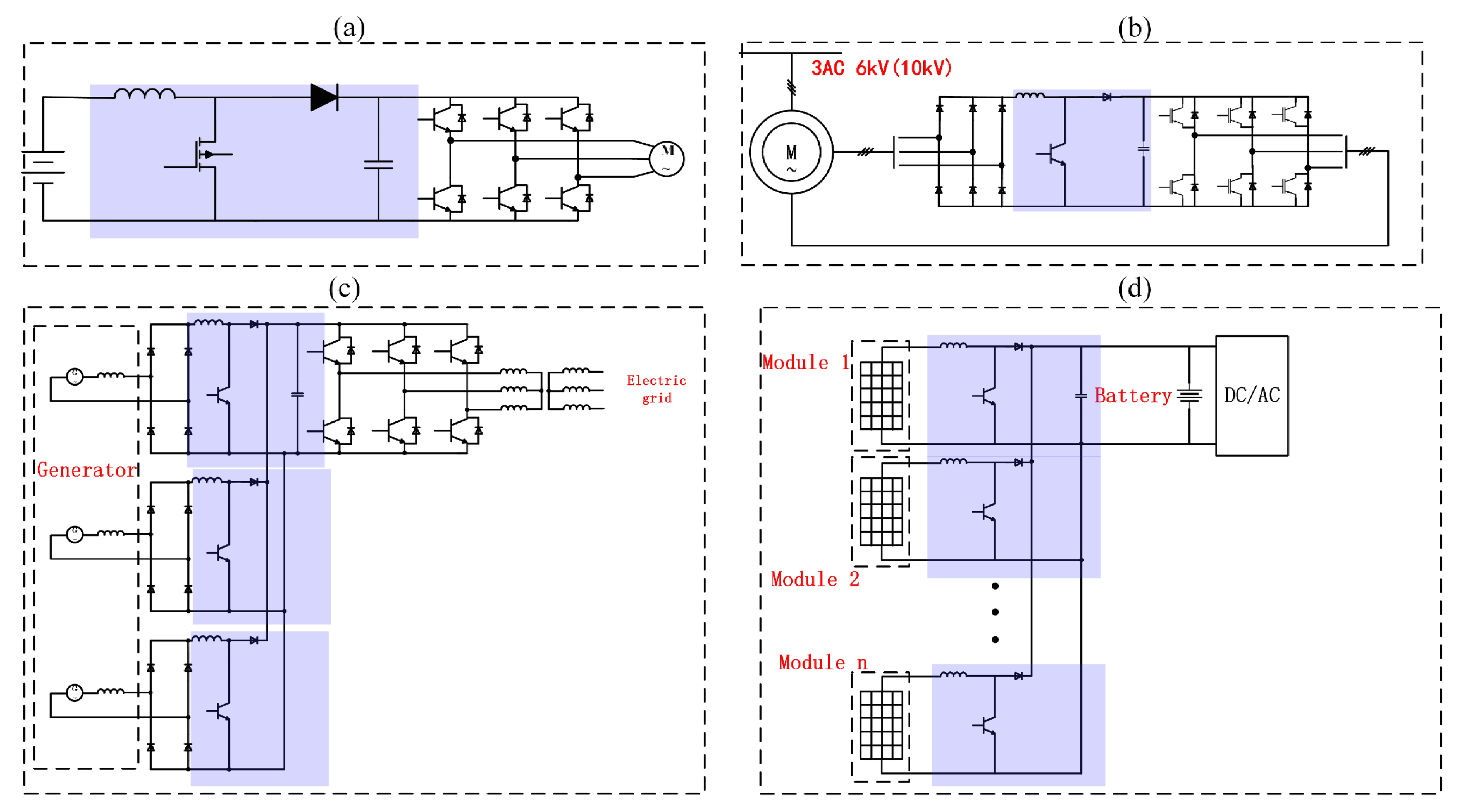
  5. Chang, H.C.; Liaw, C.M. On the front-end converter and its control for a battery powered switched-reluctance motor drive. IEEE Trans. Power Electron. 2008, 23, 2143–2156. [Google Scholar] [CrossRef]
  6. Li, C.; Wang, G.; Li, H.; Li, F.; Xia, Z.; Liu, Z. Fault-tolerant analysis of two boost inverters for open-end winding induction motor drives. J. Power Electron. 2021, 21, 647–659. [Google Scholar] [CrossRef]
  7. Kavousi, A.; Fathi, S.H.; Milimonfared, J.; Soltani, M.N. Application of boost converter to increase the speed range of dual-stator winding induction generator in wind power systems. IEEE Trans. Power Electron. 2018, 33, 9599–9610. [Google Scholar] [CrossRef] [Green Version]
  8. Xia, C.; Geng, Q.; Gu, X.; Shi, T.; Song, Z. Input–output feedback linearization and speed control of a surface permanent-magnet synchronous wind generator with the boost-chopper converter. IEEE Trans. Ind. Electron. 2012, 59, 3489–3500. [Google Scholar]
  9. Matsuo, H.; Kurokawa, F. New solar cell power supply system using a boost type bidirectinal dc-dc converter. IEEE Trans. Ind. Electron. 1984, IE-31, 51–55. [Google Scholar] [CrossRef]
  10. Chini, A.; Soci, F. Boost-converter-based solar harvester for low power applications. Electron. Lett. 2010, 46, 296–298. [Google Scholar] [CrossRef]
  11. Ganapati, V.; Steiner, M.A.; Yablonovitch, E. The voltage boost enabled by luminescence extraction in solar cells. IEEE J. Photovoltaics 2016, 6, 801–809. [Google Scholar] [CrossRef]
  12. Oucheriah, S.; Guo, L. PWM-based adaptive sliding-mode control for boost DC–DC converters. IEEE Trans. Ind. Electron. 2012, 60, 3291–3294. [Google Scholar] [CrossRef]
  13. Song, T.T.; Chung, H.S.h. Boundary control of boost converters using state-energy plane. IEEE Trans. Power Electron. 2008, 23, 551–563. [Google Scholar] [CrossRef]
  14. Chu, G.; Chi, K.T.; Wong, S.C.; Tan, S.C. A unified approach for the derivation of robust control for boost PFC converters. IEEE Trans. Power Electron. 2009, 24, 2531–2544. [Google Scholar] [CrossRef]
  15. Son, Y.I.; Kim, I.H. Complementary PID controller to passivity-based nonlinear control of boost converters with inductor resistance. IEEE Trans. Control Syst. Technol. 2011, 20, 826–834. [Google Scholar] [CrossRef]
  16. Naim, R.; Weiss, G.; Ben-Yaakov, S. H/sup/spl infin//control applied to boost power converters. IEEE Trans. Power Electron. 1997, 12, 677–683. [Google Scholar] [CrossRef]
  17. El Fadil, H.; Giri, F. Backstepping based control of PWM DC-DC boost power converters. In Proceedings of the 2007 IEEE International Symposium on Industrial Electronics, Vigo, Spain, 4–7 June 2007; pp. 395–400. [Google Scholar]
  18. Malekzadeh, M.; Khosravi, A.; Tavan, M. A novel sensorless control scheme for DC-DC boost converter with global exponential stability. Eur. Phys. J. Plus 2019, 134, 338. [Google Scholar] [CrossRef]
  19. Malekzadeh, M.; Khosravi, A.; Tavan, M. A novel adaptive output feedback control for DC–DC boost converter using immersion and invariance observer. Evol. Syst. 2020, 11, 707–715. [Google Scholar] [CrossRef]
  20. Cho, H.; Yoo, S.J.; Kwak, S. State observer based sensor less control using Lyapunov’s method for boost converters. IET Power Electron. 2015, 8, 11–19. [Google Scholar] [CrossRef]
  21. Cimini, G.; Ippoliti, G.; Orlando, G.; Pirro, M. Current sensorless solution for PFC boost converter operating both in DCM and CCM. In Proceedings of the 21st Mediterranean Conference on Control and Automation, Platanias, Greece, 25–28 June 2013; pp. 137–142. [Google Scholar]
  22. Li, X.; Chen, M.; Shinohara, H.; Yoshihara, T. Design of a low-order sensorless controller by robust H control for boost converters. J. Power Electron. 2016, 16, 1025–1035. [Google Scholar] [CrossRef] [Green Version]
  23. Cimini, G.; Ippoliti, G.; Orlando, G.; Pirro, M. Sensorless power factor control for mixed conduction mode boost converter using passivity-based control. IET Power Electron. 2014, 7, 2988–2995. [Google Scholar] [CrossRef]
  24. Das, D.; Madichetty, S.; Singh, B.; Mishra, S. Luenberger observer based current estimated boost converter for PV maximum power extraction—A current sensorless approach. IEEE J. Photovoltaics 2018, 9, 278–286. [Google Scholar] [CrossRef]
  25. Tong, Q.; Zhang, Q.; Min, R.; Zou, X.; Liu, Z.; Chen, Z. Sensorless predictive peak current control for boost converter using comprehensive compensation strategy. IEEE Trans. Ind. Electron. 2013, 61, 2754–2766. [Google Scholar] [CrossRef]
  26. Cimini, G.; Ippoliti, G.; Orlando, G.; Longhi, S.; Miceli, R. A unified observer for robust sensorless control of DC–DC converters. Control Eng. Pract. 2017, 61, 21–27. [Google Scholar] [CrossRef]
  27. Chen, C.; Li, L.; Zhang, Q.; Tong, Q.; Liu, K.; Lyu, D.; Min, R. Online inductor parameters identification by small-signal injection for sensorless predictive current controlled boost converter. IEEE Trans. Ind. Inform. 2016, 13, 1554–1564. [Google Scholar] [CrossRef] [Green Version]
  28. Tong, Q.; Chen, C.; Zhang, Q.; Zou, X. A sensorless predictive current controlled boost converter by using an EKF with load variation effect elimination function. Sensors 2015, 15, 9986–10003. [Google Scholar] [CrossRef] [Green Version]
  29. Beccuti, A.G.; Mariéthoz, S.; Cliquennois, S.; Wang, S.; Morari, M. Explicit model predictive control of DC–DC switched-mode power supplies with extended Kalman filtering. IEEE Trans. Ind. Electron. 2009, 56, 1864–1874. [Google Scholar] [CrossRef]
  30. Stitou, M.; El Fadili, A.; Chaoui, F.Z.; Giri, F. Output feedback control of sensorless photovoltaic systems, with maximum power point tracking. Control Eng. Pract. 2019, 84, 1–12. [Google Scholar] [CrossRef]
  31. Su, M.; Feng, W.; Jiang, T.; Guo, B.; Wang, H.; Zheng, C. Disturbance observer-based sliding mode control for dynamic performance enhancement and current-sensorless of buck/boost converter. IET Power Electron. 2021, 14, 1421–1432. [Google Scholar] [CrossRef]
  32. Pati, A.K.; Sahoo, N.C. A super-twisting sliding mode observer for boost inverter-based hybrid photovoltaic-battery system control. Trans. Inst. Meas. Control 2020, 42, 2139–2154. [Google Scholar] [CrossRef]
  33. Liu, J.; Laghrouche, S.; Wack, M. Observer-based higher order sliding mode control of power factor in three-phase AC/DC converter for hybrid electric vehicle applications. Int. J. Control 2014, 87, 1117–1130. [Google Scholar] [CrossRef]
  34. Liu, G.; Wang, M.; Zhou, W.; Wu, Q.; Fu, Y. A sensorless current balance control method for interleaved boost converters based on output voltage ripple. IEEE Trans. Power Electron. 2020, 36, 7138–7149. [Google Scholar] [CrossRef]
  35. Kim, S.K.; Ahn, C.K. Proportional-derivative voltage control with active damping for dc/dc boost converters via current sensorless approach. IEEE Trans. Circuits Syst. II Express Briefs 2020, 68, 737–741. [Google Scholar] [CrossRef]
  36. Min, R.; Tong, Q.; Zhang, Q.; Chen, C.; Zou, X.; Lv, D. Corrective frequency compensation for parasitics in boost power converter with sensorless current mode control. Int. J. Electr. Power Energy Syst. 2018, 96, 274–281. [Google Scholar] [CrossRef]
  37. Pahlevani, M.; Pan, S.; Eren, S.; Bakhshai, A.; Jain, P. An adaptive nonlinear current observer for boost PFC AC/DC converters. IEEE Trans. Ind. Electron. 2014, 61, 6720–6729. [Google Scholar] [CrossRef]
  38. Wang, Z.; Li, S.; Yang, J.; Li, Q. Current sensorless finite-time control for buck converters with time-varying disturbances. Control Eng. Pract. 2018, 77, 127–137. [Google Scholar] [CrossRef]
  39. Wang, J.; Zhang, C.; Li, S.; Yang, J.; Li, Q. Finite-time output feedback control for PWM-based DC–DC buck power converters of current sensorless mode. IEEE Trans. Control Syst. Technol. 2016, 25, 1359–1371. [Google Scholar] [CrossRef]
  40. Nizami, T.K.; Chakravarty, A.; Mahanta, C. Analysis and experimental investigation into a finite time current observer based adaptive backstepping control of buck converters. J. Frankl. Inst. 2018, 355, 4996–5017. [Google Scholar] [CrossRef]
  41. Ortega, R.; Bobtsov, A.; Nikolaev, N.; Schiffer, J.; Dochain, D. Generalized parameter estimation-based observers: Application to power systems and chemical–biological reactors. Automatica 2021, 129, 109635. [Google Scholar] [CrossRef]
  42. Middlebrook, R.D.; Ćuk, S. A general unified approach to modelling switching-converter power stages. Int. J. Electron. Theor. Exp. 1977, 42, 521–550. [Google Scholar] [CrossRef]
  43. Erickson, R.W.; Maksimovic, D. Fundamentals of Power Electronics; Springer Science & Business Media: Berlin/Heidelberg, Germany, 2007. [Google Scholar]
  44. Sun, J.; Mitchell, D.M.; Greuel, M.F.; Krein, P.T.; Bass, R.M. Averaged modeling of PWM converters operating in discontinuous conduction mode. IEEE Trans. Power Electron. 2001, 16, 482–492. [Google Scholar]
  45. Hernandez-Gomez, M.; Ortega, R.; Lamnabhi-Lagarrigue, F.; Escobar, G. Adaptive PI stabilization of switched power converters. IEEE Trans. Control Syst. Technol. 2009, 18, 688–698. [Google Scholar] [CrossRef]
Figure 1. The application cases of a boost converter in a power system. (a) Battery-power system, (b) wound rotor asynchronous motor system, (c) wind generator system, (d) solar cell system.
Applsci 11 07761 g001
Figure 2. The circuit topology of DC–DC boost converter.
Applsci 11 07761 g002
Figure 3. The structure of the proposed sensorless controller.
Applsci 11 07761 g003
Figure 4. Boost converter transient under the proposed sensorless controller. (a) Output voltage v, (b) estimated current i ^ , (c) duty ratio d.
Applsci 11 07761 g004
Figure 5. Response curves of boost converter under the proposed sensorless controller with different references. (a) Output voltage v, (b) estimated current i ^ , (c) duty ratio d.
Applsci 11 07761 g005
Figure 6. Transient of GPEBO with different γ . (a) estimated current i ^ , (b) estimation error.
Applsci 11 07761 g006
Figure 7. Response curves of boost converter with a step change in R. (a) Output voltage v, (b) estimated current i ^ , (c) estimation error.
Applsci 11 07761 g007
Figure 8. The phase portrait of closed-loop system. The black point is the equilibrium. The red lines are the state trajectories.
Applsci 11 07761 g008
Figure 9. Schematic diagram of the experimental platform.
Applsci 11 07761 g009
Figure 10. Response curves of boost converter under the proposed sensorless controller (experiment). (a) Output voltage v, (b) estimated current i, (c) duty ratio d.
Applsci 11 07761 g010
Table 1. Simulation/experimental set—points and physical parameters.
ParameterSymbol (Unit)Value
Input voltage E ( V ) 6
Reference output voltage x 2 ( V ) 12
Gain x 2 / E 2
Resistance R ( Ω ) 100
Inductance L ( mH ) 5
Capacitance C ( μ F ) 680
Publisher’s Note: MDPI stays neutral with regard to jurisdictional claims in published maps and institutional affiliations.

