Review

Performance of a Ductile Hybrid Post-Tensioned Beam-to-Column Connection for Precast Concrete Frames under Seismic Loads: A Review

1
Department of Civil Engineering, Faculty of Engineering, University of Malaya, Kuala Lumpur 50603, Malaysia
2
Department of Civil Engineering, College of Engineering, King Khalid University, Asir, Abha 61421, Saudi Arabia
*
Authors to whom correspondence should be addressed.
Appl. Sci. 2021, 11(16), 7497; https://doi.org/10.3390/app11167497
Submission received: 23 June 2021 / Revised: 1 August 2021 / Accepted: 9 August 2021 / Published: 16 August 2021
(This article belongs to the Topic Advances in Dynamics of Building Structures)

Abstract

:
The performance of precast concrete frame structures against seismic loads mainly depends on the beam-to-column connection. A ductile hybrid connection consists of unbonded post-tensioning steel and bonded reinforcement bars, both of which provide overall moment resistance to the frame. Post-tensioning steel acts as a restoring force which brings the structure back to its initial position upon unloading. Mild steel acts as an energy dissipator which yields in tension and compression. To evaluate the performance of precast frame structures, the structural engineer requires extensive knowledge of the complex nonlinear behavior of the connection. Standardization to mass produce is one of the benefits of precast construction, but with standardization in design there is severe risk. All previous earthquakes have clearly shown that continuous repetition of accepted practice without proper engineering review can lead to disaster. It is important to understand how different parameters of the connection influence the behavior and performance of the frame against seismic loads. The present study helps structural engineers and researchers with a detailed review of hybrid post-tensioned connections. This review is focused mainly on precast beam-to-column connections, studies on the development of hybrid connections, performance evaluations of hybrid connections, and the performance evaluation of precast frames with hybrid connections.

1. Introduction

Precast concrete frame structures are elements prefabricated in the factory and then erected at the site. Precast concrete structures are widely used as an alternative to conventional cast-in-situ structures, mainly due to the speed of construction, better quality control, lower manpower requirements, and less activity at the site [1]. According to an Armenian earthquake report, numerous poor connections have contributed to the collapse of precast frame buildings, as they were insufficient to resist the seismic loads [2]. The poor performance of precast structures in the 2012 Emilia-Romagna earthquake was also due to an insufficient understanding of connections [3,4]. The connection between different precast elements is important, and it significantly governs the response of the structure [5]. To address this issue, the Precast Seismic Structural Systems (PRESSS) research program began in 1989 for the development of efficient precast connections in seismic zones [6]. The program was initiated to provide design recommendations for precast structures [7]. The hybrid connection was successfully developed during this program, and contained unbonded post/tensioning steel and bonded mild steel bars.
The performance of precast concrete frame structures subjected to earthquake loads depends on the beam column connection strength, stiffness, energy dissipation, and ductility [8]. A comprehensive review of the performance of hybrid post-tensioned connections based on various parameters is presented. This will help structural engineers and researchers to develop an in-depth knowledge of connection behavior of precast frames under seismic loads. Previous earthquakes [2,9] showed that connections should not be used without a proper understanding of their complex behavior. In the present study, the code requirements of precast structures in seismic zones are discussed. Further, the development of hybrid connections by the PRESSS is also mentioned. This will serve as a real example for researchers to develop more efficient connections. Hybrid connections have self-centering capabilities if post-tensioning steel remains elastic [10]. Since the plastic hinge is in the connection region, damage to the structural components is minimal. Moreover, dry connections provide optimum speed in precast construction [11].
The major drawback in hybrid connections is energy dissipation. Post-tensioning steel does not provide enough energy dissipation [12]. Mild steel was first used by Cheok and Stone [13] as an energy dissipator. Experimental results showed that with mild steel bars, the energy dissipation was low compared to that of their monolithic counterparts. With low energy dissipation, the drift of the structure increases [14]. Several attempts were made to improve energy dissipation to reduce displacement demands [15]. The unique gap opening phenomenon at the beam–column interface of hybrid connections allows the use of several types of energy dissipators. Some of the energy dissipators in literature include metallic yielding devices [16,17], friction devices [18], bracing systems [19], and smart materials [20]. Hybrid connections with different energy dissipators are evaluated based on performance.
Apart from performance, connections are also examined based on their feasibility in the precast construction industry. A connection that is simple, economical, and efficient will help the precast industry to benefit from precast construction technology. A lack of feasibility is the main reason that few connections found in the literature are put to practical use. One example is the connection proposed by Yang et al. [21], which contained several components, including column plates, steel I sections, friction devices, and beam plates. Englekirk [11] states that the connection must be economical or else it will not be used. Connection feasibility includes a simple assembly process, easy and economical production, the accommodation of production, and erection tolerances. The connection should not interfere with the function and aesthetics of the structure. Due to the achievement of both performance and feasibility requirements, the developed hybrid connection was not only was included in code [22] but has also been widely used in the precast industry. Most of the latest research [23,24] has been focused on performance and not feasibility requirements. As a result, the connections are not used in the precast industry. The study highlights the importance of both performance and feasibility requirements, and will help researchers to improve or develop practical and efficient solutions.
In past two decades, several researchers have published work on precast connections. The literature highlights the importance of understanding the behavior of connections and the effect they have on the global performance of various types of structures. Therefore, the main objective of study is to present a comprehensive review on the performance of hybrid post-tensioned connections based on various parameters. The effect of various energy dissipators on the performance of hybrid connections is also discussed. The energy dissipation of the hybrid system can be improved with the use of various energy dissipators to reduce displacement demands. Apart from performance, the connections are reviewed based on their feasibility in precast construction. Feasibility is an important aspect of connections which cannot be ignored in the precast construction system. The study discusses the current state of research on hybrid connections. Accordingly, recommendations and suggestions are provided for future research.

2. Types of Precast Frame Connections

To evaluate the connections, it is important to know the code classification of connections and the performance acceptance criteria. ACI-318-19 [25] defines two types of precast moment resisting frame connections:

2.1. Rigid Connections

In precast frames, when the plastic hinge is formed outside the connection region, it is called a rigid connection. The connection will have greater strength when compared to beam elements; hence, a plastic hinge forms in the precast beam away from the connection. In this type of connection, energy is dissipated as in the case of monolithic concrete frames. The current paper does not focus on this type of connection.

2.2. Ductile Connections

In precast frames, when the plastic hinge is formed inside the connection region, it is known as a ductile connection. The connection is weaker when compared to beam elements; hence, a plastic hinge forms in the connection and beam element remains relatively undamaged. The current paper is focused on this type of connection.

2.3. Comparison of Rigid and Ductile Connections

Rigid and ductile connections have distinct performance and behaviour charecteristics. Table 1 summarises the difference between these connections. For design, it is important to know how the connections are classified based on their behaviour.

2.4. Types of Ductile Connections

2.4.1. Tension/Compression Yielding

In this type, connection elements yield in both tension and compression, through which energy is dissipated. A gap is left between the beam and column, as shown in Figure 1 and Figure 2, to allow yielding in tension and compression; hence, it is also known as a gap joint connection [26].

2.4.2. Friction

In this type of connection, energy is dissipated through friction when a slip occurs between connecting elements [26]. Figure 3 shows a gap which is provided to allow the slip to occur in both directions.

2.4.3. Nonlinear Elastic

In this type of connection, post-tensioning steel is used (as shown in Figure 4 and Figure 5), which is unbonded up to certain length and is partially stressed so that it always stays elastic [26]. A crack opens at the beam and column interface when flexural stress exceeds the precompression stress provided by strands. The nonlinearity is not related to material but is related to geometry. The energy dissipation is much lower in this connection, but self-centering capability of the frame is good due to the post-tensioning steel behaving like elastic.

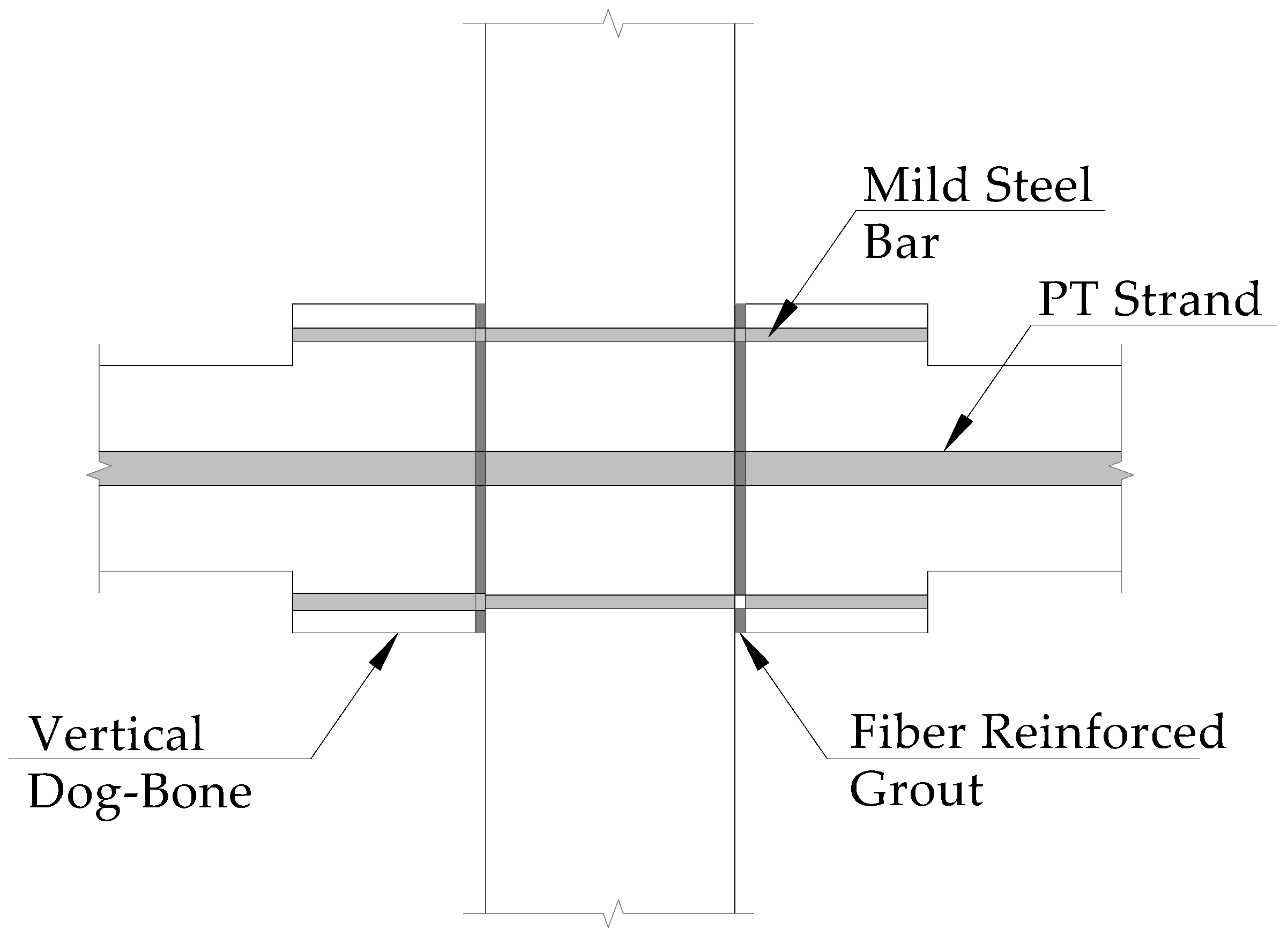
3. Hybrid Frame Concept Description

The frame is described as hybrid because it is a combination of post-tension and precast concrete construction. The hybrid frame and its deformed and undeformed shapes are shown in Figure 6, Figure 7 and Figure 8. The precast columns are erected first and then beams are erected on temporary corbels. Mild steel bars are placed in the beam troughs and are passed through column sleeves. The interface gap between the beam and column is grouted with fiber-reinforced grout. The steel bars are also grouted at same time. After the grout has gained strength, post-tensioning steel is installed and stressed. The columns behave as rigid bodies and deformation occurs only in the beam-to-column joint. The post-tensioning steel is partially stressed and debonded to always remain elastic. Hence, the post-tensioning steel acts as a restoring force and re-centers the structure, with no residual displacement after an earthquake event. Mild steel bars dissipate energy by yielding in tension and compression. They are debonded up to certain length to avoid fracture.

4. Code Requirements for Moment Frames

4.1. Emulative and Non-Emulative Precast Concrete Frame Structures

Emulative precast concrete frames are classified as those frames which behave like cast-in-situ concrete frames. The hybrid precast frame is classified as non-emulative precast frame because it does not behave as a monolithic cast-in-place frame. Hybrid frames are special precast frames whose connections are ductile, where yielding takes place in connections. Hybrid moment frames do not satisfy the requirement of Chapter 18 of ACI-318-19 [25] for frames of monolithic construction. According to section 18.2.1.7 of ACI 318-19, such frames are accepted if it is demonstrated by experiments and analysis that the proposed system have the strength and toughness equal to or exceeding that provided by a reinforced concrete structure, satisfying chapter 18 of ACI-318-19. The hybrid frame does not satisfy the prescriptive requirements of Chapter 18, but its performance has been demonstrated by experimental studies, satisfying the seismic performance requirements [13]. Hybrid frames are included in ACI 550.3M [22] as a type of special precast concrete moment frame for use based on experimental evidence. In ACI 374.1-05 [29] the experiment procedures and performance acceptance criteria are described. The drift ratio is calculated as shown in Figure 9.

4.2. ACI 374.1-05 Requirements for Experimental Validation

Experiment requirements, guidelines, and procedures
  • Design procedures should be developed before testing to estimate the preliminary size of test specimens.
  • At least one specimen must be tested for each characteristic configuration.
  • The test specimen should be scaled large enough to represent all characteristics of the actual size of specimen.
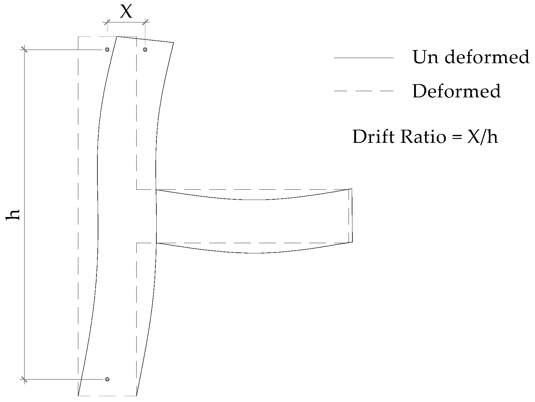
  • The specimen should be subjected to displacement-controlled cycles according to their drift ratios.
  • Three equal and cyclic displacements should be applied at each drift ratio.
  • The drift ratio should be gradually increased until a 3.5% drift ratio is reached.

4.3. Acceptance Criteria

According to ACI 374.1-05, the following criteria must be met for the satisfactory performance of a test specimen:
  • The lateral resistance should be equal or greater than the nominal lateral resistance.
  • For the frame to behave as a weak beam strong column, the maximum lateral resistance of the specimen should not exceed the nominal lateral resistance multiplied by the overstrength factor.
  • For the targeted drift ratio, at the completion of the third cycle the lateral resistance in both loading directions should not be less than 0.75 times the maximum lateral resistance of the specimen.
  • The energy dissipation ratio should not be less than 1/8 (that corresponds to 12.5% damping).
  • Secant stiffness from targeted peak positive and negative drift ratio should not be less than 0.05 times the initial stiffness.

5. Testing and Development of Hybrid Connections (PRESSS Research Program 1989)

Priestley [6] reported an overview of the Precast Seismic Structural Systems (PRESSS) Research program. This research program was started in 1989 as part of the United States–Japan protocol on large-scale testing for the seismic response of precast concrete buildings [6]. The purpose of this program was to develop recommendations for the seismic design of precast buildings. The hybrid precast connection was developed during the four phases of this program (I, II, III, IV (A and B)).
During Phase I, Cheok and Lew (1991) [30] experimented with precast concrete beam column assembly using high-strength post-tensioning bars fully grouted as shown in Figure 10. The specimens failed because of their inability to carry higher loads due to the yielding of post-tensioning bars at the column–beam interface. A plastic hinge formed in the interface region. The gap opening at the interface was roughly 13 mm. The yielding occurred at this interface, which resulted in loss of post-tensioning force. The precast column beam assembly was found to be as strong as the monolithic sub-assembly. The post-tensioning force contributed to strength. Precast assembly was found to be ductile in a similar manner to monolithic sub-assembly. The yielding and gap opening at the column–beam interface provided ductility. The energy dissipated per cycle by the post-tensioned specimen was 30% compared to its monolithic counterpart. Total energy dissipation to failure was 80%. Overall, the assembly performed well, but energy dissipation, which is very important factor for seismic resistance, was very low on per cycle basis.
In Phase II, Cheok and Lew (1993) [31] experimented with a precast assembly using two beam specimens. For specimen 1 (Figure 11), strands were used. For specimen 2 (Figure 12), PT bars were used and moved closer to the center. Both specimens were fully grouted. The failure was similar for both specimens. They failed due to the yielding of post-tensioning steel, the crushing of concrete, and a gap opening at the column and beam interface. The width of the opening increased as the post-tensioning steel moved closer to the centroid. The type of post-tensioning steel did not affect the width of the gap opening. The precast specimen strength exceeded that of their monolithic counterpart. Moving the post-tensioning steel closer to the centroid did not have any adverse effect on connection strength. It reduced strain in the post-tensioning steel. The precast assembly was found to be more ductile than its monolithic counterpart. The energy dissipated by the strand post-tensioned specimen was greater than that of post-tension bar specimen. The energy dissipated per cycle was less than that of the monolithic specimen. Total energy dissipation for the precast post-tensioned specimen was higher than that of the monolithic specimen because of the higher displacement ductility achieved by the precast specimen. Overall, the precast connection performed well but the energy dissipation per cycle was still low.
In Phase III, Priestley and Tao (1993) [32] performed a numerical analysis of a column and beam assembly with partially unbonded post-tensioned tendons (Figure 13). Tendons were unbonded along the column length and extended 48 in (1.22 m) into the beam. The tendons were placed closer to the beam centroid, as shown in Figure 13. Priestley and Tao [32] performed a dynamic nonlinear analysis to study the concept of partially unbonded frames. They predicted that the debonded system would result in the maintenance of prestress compression after seismic displacement. Residual displacement would be negligible. They suggested special spiral reinforcement at the beam ends to ensure satisfactory performance in the plastic hinge regions. Ductility demands of partially debonded and fully bonded tendons would be the same; however, for short period structures high displacement ductility demands can be expected. They suggested experimental research to confirm the numerical results.
Cheok and Lew (1994) [33] experimented using two specimens (Figure 14 and Figure 15), similar to in phase II. The only change was that the prestressing steel was unbonded at the joint region. Both specimens failed in same way. Failure was due to post-tensioning steel yielding, crushing of concrete, and a gap opening at the column and beam interface. The width of the gap opening was not affected by partially debonding prestressing steel. The specimen strength exceeded that of its monolithic counterpart. Moving post-tensioning steel closer to the centroid did not have any adverse effect on connection strength. The precast assembly was found to be more ductile than its monolithic counterpart. The energy dissipation was improved compared to fully bonded post-tensioning steel. Total energy dissipation for the precast post-tensioned specimen was greater than for the monolithic specimen because of the higher displacement ductility achieved by the precast specimen. Overall, the precast connection performed well, but the energy dissipation was still around 60% compared to its monolithic counterpart.
MacRae and Priestley (1994a,1994b) [12,34] experimented using a 2/3 scale unbonded post-tensioned precast concrete column beam assembly, with details as shown in Figure 16. The behavior of specimen was characterized by the gap opening and closing at the column–beam interface. They reported that the provision of suitable calculated unbonded length was sufficient to prevent yielding of the tendons. However, it should be ensured that the anchorage details of the post-tensioned tendons and compression zones in the column beam contact area are detailed satisfactorily. The strength of the connection was found to be satisfactory. No significant stiffness degradation was noticed even at a 4% story drift. The sub-assembly behaved well and attained large lateral drifts without significant damage. The energy dissipation was very little. The residual displacement after unloading was found to be negligible, indicating self-centering capability.
In Phase IV-A, Cheok and Stone (1993) [13] experimented with precast assembly (Figure 17) using five beam specimens, as shown in Figure 18. The variables were the type of post-tensioning steel and the type and amount of low-strength steel and partially and fully bonded PT steel. The fully bonded strand and mild steel specimen failed prematurely due to bond failure of the mild steel at 1.7% story drift. The unbonded PT bar and fully bonded mild steel specimen failed due to the fracture of the mild steel bar at 3% and 3.6% story drift, respectively. Specimens A and B were not tested to failure. The purpose of this test was to determine which type of PT steel behaved best (bar or strand). The strand type lost 30% of the initial force, while the bar type lost 80% of the initial force. Loss of force in the strand type was due to reseating of the chunks, while that lost in PT bars was due to yielding and crushing of beams. Failure of specimen C was due to the shear cracks that formed at the interface of the T section and dog bone region. All specimens performed well in terms of connection strength. The low drift for the bonded strand and the mild steel specimen was due to premature bond failure. The location of PT steel in the center improved the cyclic energy dissipation. Energy dissipation dropped after the fracture of mild steel.
In Phase IV-B, Cheok and Stone (1994) [13] experimented with precast beam column assembly (Figure 19) using four beam specimens, as shown in Figure 20. Unbonded post-tensioning steel and a bonded mild steel bar were used. The variables were the amount and type of low-strength steel. Crack widths reported in both the column and beams were very small. The closure of gap openings at column–beam interface was zero, even at 3.5% story drift. Specimen M-P-Z4 failed due to the fracture of mild steel bars. PT steel in this specimen was 0.93 fpu, indicating it remained elastic throughout the test. Loss in PT steel was 0.06 fpu. Hence clamping force was maintained.
Specimen N-P-Z4 failed due to the bond failure of stainless-steel bars. The assembly was subjected to 6% story drift, and the authors reported that yielding of PT steel occurred at 5.9% story drift. Only 25% of initial stress remained in PT steel, but it was still enough to produce sufficient clamping force to resist the gravity loads. No vertical slip was reported. Specimen O-P-Z4 failed due to the fracture of mild steel bars at 3.5% drift. PT steel in this specimen remained elastic, with peak stress of 0.88 fpu with 0.02 fpu total loss in prestress. Specimen P-P-Z4 failed due to the fracture of mild steel bars. Hawileh et al., 2006 [35,36] suggested that the bar failure observed in the experiments was due to low cycle fatigue. The specimen was subjected to 57 cycles before it failed. All specimens performed well in terms of connection strength. All specimens had slightly lower story drifts than their monolithic counterparts. However, the precast specimens were subjected to four times more cycles than monolithic specimens. In that case, precast specimens could have slightly higher story drifts.
M-P-Z4, O-P-Z4, and P-P-Z4 behaved like monolithic specimens up to 1.5% story drift. N-P-Z4 performed poorly due to bond failure of the mild steel. O-P-Z4 had 50% more mild steel than M-P-Z4, and both performed in same way up to 1.5% story drift. Stainless steel and the grade 60 reinforcing bar showed no differences in performance in terms of cyclic dissipation.

5.1. Outcome and Discussion of the PRESSS Program

In total, 18 precast post-tensioned specimens were tested. The variables included the amount and location of post-tensioning steel, the type of bonding (fully, partial, or unbonded), and the type and amount of low-strength steel. The strands performed better than the high-strength bar. The prestressing steel location at the centroid of beam resulted in more energy dissipation and less strain in PT steel. Low-strength steel was located at top and bottom, which acted as energy dissipators. This steel was partially debonded to delay the fracture of the bars.
The experimental studies showed that hybrid connections could perform like monolithic connection in terms of strength, ductility, and energy dissipation, with minimal damage to the structure because the plastic hinge is in the connection region. The damping of monolithic specimens was greater compared to that of precast frames. This was due to complete damage of monolithic beams, whereas in precast specimen failure and yielding was only in the connection region. Beam and column damage was minimal in precast specimens. Even with the fracture of energy-dissipating bars, there was no actual connection failure. The connection attained 6% drift before failure, indicating that even at an unanticipated drift level, the structure would survive. Overall, the hybrid connection performed well against seismic loads.
Column fabrication for the hybrid frame to accommodate connections requires ducts for mild steel bars and post-tensioning steel, and is an easy process. However, beams require troughs at the top and bottom and additional shear detailing at this reduced section, which will increase congestion and costs. Embedment of straight PT ducts during fabrication is easy. The erection of beams require temporary corbels, and beams can be easily erected due to large tolerance, reducing the crane time. The weight of mild steel bars can easily be handled by a single person. The grouting and tensioning process requires a skilled workforce and can be expensive in some countries. Co-ordination between precast and post-tensioning contractors is required. PT steel and mild steel bars have sufficient cover for protection from deterioration. However, the unbonded portion of PT steel and mild steel at the beam–column interface can be at risk of damage. It is difficult to repair damaged energy-dissipating bars in hybrid systems. Special consideration needs to be given to hybrid frames for connecting the floor diaphragm at the beam–column interface where the gap is designed to occur. The floor diaphragm can either be isolated at the gap area or connected to the beam where expect local damage is expected.

5.2. Energy Dissipation
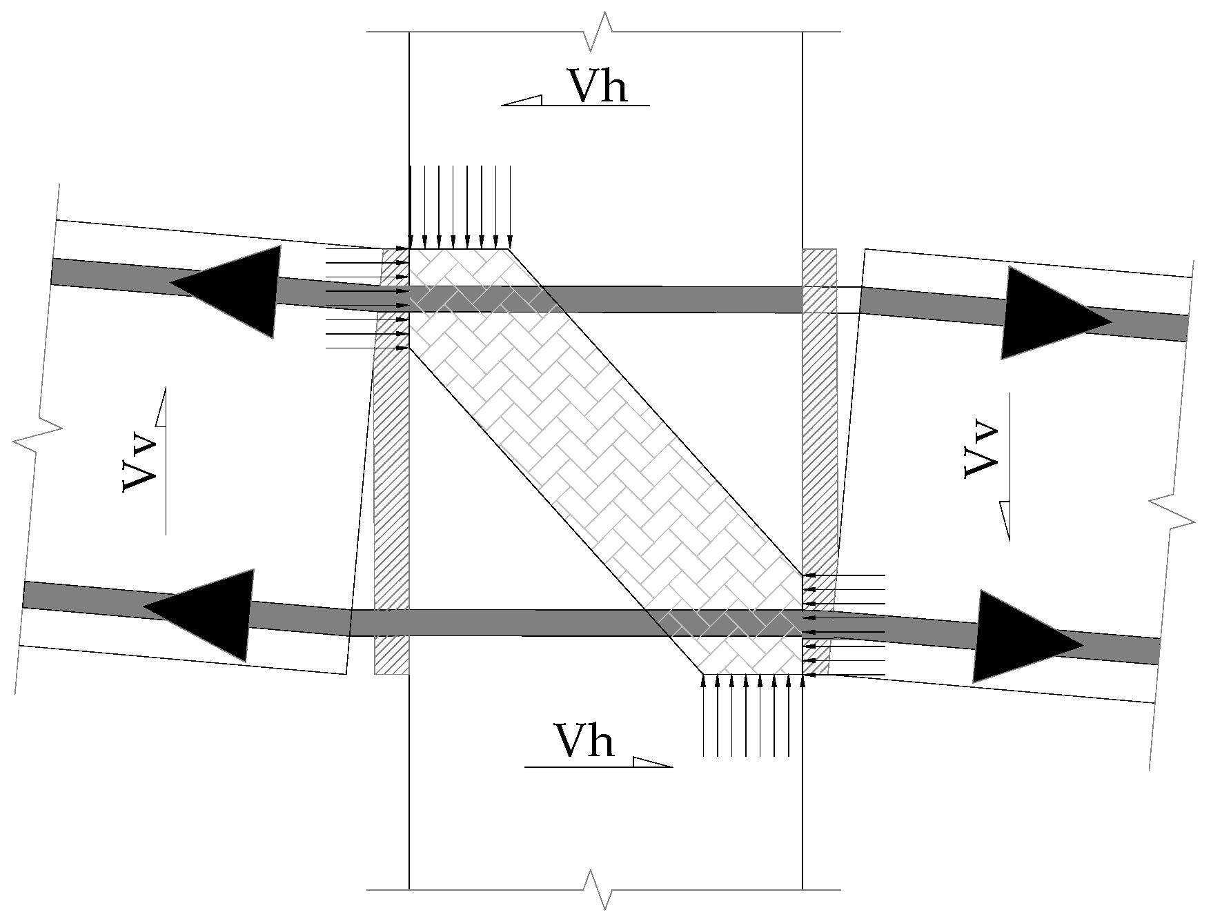
Post-tensioning steel did not contribute greatly to energy dissipation. It acted as a clamping force and contributed to self-centering of the structure. All the energy dissipation is due to the low-strength bars used. Energy dissipation of the hybrid connection decreased when these bars failed due to fractures or bond slip. Due to poor energy dissipation, the hybrid frame will have large displacement or drift demands. Hence, several attempts were made to improve the energy dissipation of this system to reduce displacement requirement of the structure.

5.3. Joint Shear

The shear requirement at the beam column joint is a function of both gravity and seismic loads. Vertical shear in the joint area is transferred by the friction induced by post-tensioning for both gravity and lateral loadings [29]. The friction is induced by the combination of post-tensioning force and the moment couple generated by all the loads [37]. However, to ensure these two mechanisms, post-tensioning force should not be lost, and the compression segment should have sufficient resistance. Since the plastic hinge is expected to occur in the joint region, free rotation of the beam at the joint is allowed. There is no need for permanent corbels. However, if a corbel is used, it will provide extra vertical shear resistance.
Prestley and MacRae [12,34], through experiments and numerical analysis, showed that shear forces in the joint area were carried mainly by diagonal compression struts (Figure 21). The shear resistance of hybrid system was found to be better than in the conventionally reinforced frame. No degradation of shear strength was observed in the tests. Hence, less joint and beam shear reinforcement is needed in the hybrid system [38]. However, sufficient confinement steel should be provided to prevent brittle compressive failure. When the joint undergoes large rotations, high compressive force is concentrated at top and bottom of the beam. Cheok and Stone used armor angles at the top and bottom of the beam, which were effective in preventing compression-induced spalling [13]. Priestley and MacRae [12] used spiral confinement reinforcement, as shown in Figure 22.

5.4. Dynamic Properties

The strain compatibility equations do not apply to hybrid connections due to combined nonlinear behavior of unbonded post-tensioning steel and bonded bars. Numerical analysis to predict connection behavior is a complex process. Hence, the design of precast frames with a hybrid connection involves the need for precast structural engineers with in-depth knowledge. According to code, all connections were tested to displacement-controlled cyclic loading. The actual earthquake scenario is of a dynamic nature. Hence, the dynamic behavior of the connection should be studied. This can be done either by numerical nonlinear dynamic analysis or by using shake tables. Several attempts have been made to study the dynamic behavior or hybrid system.

6. Further Research on Hybrid Connection

6.1. Analytical Research on Hybrid Connection

El-Sheikh et al., 1999 [39] performed a nonlinear push-over static and time-history analysis of two six-story frames with hybrid connections. Fiber and spring analytical models were developed. They reported that hybrid frames were adequate for severe seismic loads in terms of strength, ductility, and self-centering capabilities. Hybrid frames had large displacements compared to monolithic frames due to the small amount of energy dissipation, whereas the residual displacement could be smaller.
Cheok et al., 1998 [40] developed a hysteretic model based on hysteretic behavior from phase IV-B experiments. They modelled the stiffness, strength degradation, and pinching to characterize force-deformation loops. Their empirical approach is not reliable because of the complex nonlinear behavior of hybrid frames. The combined behavior of unbonded PT and mild steel does not follow the strain compatibility. Hence, it is difficult to predict the moment curvature of the hybrid frame connection.
Pampanin et al., 2000 [41] developed a method for section analysis of hybrid connections based on member strain compatibility and local strain incompatibility between steel and concrete. His proposed method correctly predicted the experimental results of phase IV-B.
Hawileh et al., 2009 [42] performed nonlinear finite element analysis for hybrid connections to predict behavior under cyclic loads. The model predicted the experimental behavior with good accuracy. Laboratory experiments are best for studying connection behavior, but they are tedious and expensive. If carefully modelled, numerical analysis can be a good alternative to laboratory experiments. They allow the investigation of connections with different loadings and design parameters. This is particularly the case with the availability of high-performance computers.
Hawileh et al., 2006 [35,36] developed a non-dimensional design procedure for the design of hybrid frames. Laboratory results from phase IV indicated that the failure mode of precast hybrid connections was due to bar fracture and bond failure. Hawileh et al. developed bar fracture criteria which consider low-cycle fatigue under combined axial and bending strains. The proposed formulation is simple compared to the iterative step-by-step procedure.
Chen et al., 2020 [43] developed an automatic optimum design procedure for the hybrid system using a genetic algorithm in MATLAB. The proposed formulation is simple compared to the iterative step-by-step procedure.
Ertas et al., 2006 [44] experimented hybrid connections with different percentages of mild steel, and found that a 30% mild steel contribution to overall flexural capacity was sufficient for negligible residual displacement. With an increase in the mild steel percentage, the energy dissipation increased. However, with excess mild steel, residual displacement may not be negligible due to PT force not being sufficient to yield the mild bars in compression and bring the system back to the initial position.
Ozden et al., 2010 [45] proposed a new method for hybrid frame section analysis and a hysteretic model based on residual deformation because of the strain incompatibility between concrete, mild steel, and PT steel. The proposed model shows good comparison with test results.
Kim et al., 2002 [46] studied the beam growth phenomenon in RCC frames. Due to flexural cracking at the beam column joint, the horizontal distance between the column and centerlines increases. This is termed as beam growth (Figure 23). He reported an increase in column shear demands of up to 86% due to beam growth. The phenomenon also exists in hybrid frames, as PRESSS program experiments reported an up to 13 mm gap opening at the column–beam interface.
The gap opening in hybrid system may look favorable in terms of ductility, but it may also lead to undesirable beam growth. Hybrid frame behavior is complex due to non-linearities. Hybrid frames displacement demands are high due to less energy dissipation and can undergo large drifts.

6.2. Various Energy Dissipators in the Literature for Hybrid Frame Connections

Several attempts have been made to improve the energy dissipation of the hybrid connection to reduce the displacement demands.
To address the large displacement that may be expected during earthquakes for certain frames with hybrid connections, Morgen et al., 2004 [14] developed a friction damper for hybrid connections. They reported that a large amount of energy dissipation was provided by friction dampers while maintaining the self-centering capability of the frame. Dampers can be replaced after an earthquake event. The dampers are visible and may interfere with the architectural appearance of the structure.
Song et al., 2015 [47] performed experiments using hybrid frames (Figure 24) to study the behavior of frames under cyclic loading. A friction device was used instead of mild steel bars. The viscous damping achieved by this system was 11%, whereas the code requirement was 12.5%. The proposed frame confirmed its self-centering capability.
Due to the type of dissipators used, the crushing of concrete at the column–beam interface was greatly reduced. This indicated that research must be done on different types of energy dissipators to obtain potential benefits and improvements in the hybrid system.
Wang et al., 2018 [48,49] proposed a replaceable energy-dissipating bar placed at the sides of the beam, as shown in Figure 25. This led to no interference with the slab connection.
The mild steel bars can be easily replaced after an earthquake event. The main drawback is the performance of the connection under fire load, as the bars are exposed and may require fire protection.
Wang et al., 2019 [50] proposed a replaceable energy-dissipating bar placed at the top of the beam (Figure 26). The connection performed well in terms of strength, ductility, and energy dissipation. However, it may not perform well under fire loads since it is exposed, and the connection may interfere with slab connection.
Geng et al., 2020 [24] proposed a new hybrid connection with a damper, as shown in Figure 27. The connection performed well with regard to seismic loads. The energy dissipators were placed outside the beam on the sides.
Qian et al., 2020 [51] tested unbonded post-tensioned precast concrete frames with no mild steel for a sudden column removal scenario. The test indicated that the frame achieved required a load redistribution capacity to mitigate progressive collapse. Column removal duration in the test was 0.008 s and 0.005 s, satisfying the DoD requirement that the column removal duration should be less than 1/10 natural period of vibration. Weights were attached to the beams, which acted as gravity loads. The test setup accurately replicated the sudden column removal scenario due to blast load. However, the flooring system was not considered in the test.
Yang et al., 2021 [21] performed a test on a self-centering single-bay two-story hybrid frame. This consisted of an RC column with unbonded PT steel bars and steel concrete hybrid beams with four unbonded PT strands. Self-centering was provided by PT steel, and energy dissipation was provided by web friction devices at beam ends. Two frames with PT steel and one frame without PT steel were examined. The PT frames performed better than the non-PT frame in terms of bearing capacity, ductility ratio, and self-centering capacity, with values 88%, 62%, and 272% higher, respectively. Energy dissipation was better in PT frames as compared to the non-PT frame specimen. The beam column connection in the proposed frame contains too many components, including column plates, steel I sections, friction devices, and beam plates. The connection is complicated compared to the bonded mild steel connection. With all those connection components, energy dissipation mainly took place at the gap opening interface of the friction device and PT steel. In the proposed beam column connection, the hinge was location away from the column. Nakaki et al. [52] reported three drawbacks of having a hinge location away from the column: (a) The overstrength requirement in the connection becomes very large; (b) The connection relocated 0.91 m from the column face must be twice as strong as the hinge; and (c) The rotational ductility demand will increase. Hence, the proposed connection experienced damage not only in the hinge region but also at the steel beam ends, which is unfavorable in performance-based design. The connection also interferes with the floor system, and the gap opening area requires special attention when connecting the floor system.
Hazaveh et al., 2020 [53] investigated the efficacy of a viscous energy dissipator device for self-centering rocking structures which have a distinctly different dynamic response compared to fixed base structures. The system performed well in terms of displacement, base-shear, and acceleration demands. Viscous dampers can dissipate significant energy. However, their reaction loads can increase the foundation size and base shear demands. The study adopted the single degree of freedom (SDOF) method to evaluate the dynamic response of the structure. Nonlinear dynamic finite element analysis is more accurate than the SDOF method.
Ponzo et al., 2019 [54] performed experiments and analysis with regard to a post-tensioned timber framed building with yielding steel angles as dissipators. A rocking mechanism was created at beam-to-column and column-to-foundation connections. Dynamic testing was performed using a shaking table with different specimen configurations with and without dissipators. The frame with dissipators performed well in terms of story drifts due to the high energy dissipation provided by steel angles (Figure 28 and Figure 29). Concentrated yielding was achieved by milling certain portion of steel angle. The frame experienced no damage under seismic loading. Reversible earthquake loading imposes fatigue on steel angles, which dissipates energy by yielding. Hawileh et al., 2006 [35,36] indicated that low cycle fatigue is the reason for bar fracture that occurred in the PRESS phase IV-B test specimens. Hence, it is important to study the fracture criteria in metallic yielding devices as they are subjected to low cycle fatigue.
Ponzo et al., 2019 [55] performed tests on post-tensioned timber framed structures with bracing systems and U-shaped flexural steel dampers. The braced frame experienced a significant reduction in drift (60% less) at the design seismic level as compared to bare frames.

7. Recommendations and Suggestions

Based on the current state of research, the following recommendations and suggestions are presented below:
  • The connection acceptance criteria of ACI 374.1-05 are based on assumptions. Hence, nonlinear dynamic analysis with actual ground motion time histories is recommended. Various frame configurations, including different bays, floors, and beam depths, should be analyzed using the proposed connections.
  • The unique gap opening phenomenon of hybrid connection provides ductility. However, a large amount of shear force acts on columns, and the distance between columns increases to accommodate this gap. Such an unfavorable response of frames should be estimated and considered in the design.
  • Strong column weak beam criteria must be satisfied to ensure the assumed behavior of the frame.
  • Connections must be evaluated based on feasibility before experimenting. This includes ease of fabrication, ease of erection, cost, durability, and architectural aspects.
  • Detailing in the expected hinge area is important to ensure the gap opening. Connections should be designed considering this detail.
  • PT steel remains elastic, but energy dissipators are usually damaged after an earthquake. The connections should be developed using smart materials which do not require repair after seismic events.
  • To avoid spalling and ensure the shear transfer mechanism, the compression zone area must be properly detailed with confinement steel or armor angles.

8. Conclusions

The experimental and analytical studies showed that the hybrid beam column connection performed well under seismic loads. The following main conclusions can be drawn from the present study:
  • The hybrid frames have self-centering capabilities, provided the amount of mild steel is optimized. With an increase in mild steel percentage, energy dissipation increases.
  • If the post-tensioning force is not sufficient to yield the mild steel in compression, the frame will not return to its initial state.
  • The strength of precast hybrid connection is almost equal to that of its monolithic counterpart. Both the mild steel bar and post-tensioning steel contribute to the strength of connection.
  • Hybrid frames can attain more drift due to the gap opening phenomenon at the beam–column interface.
  • The energy dissipation of the hybrid frame connection is less than that of monolithic frames.
  • The failure of the precast hybrid connection is mainly due to mild steel bar fracture or bond failure. Crushing of concrete in the compression zones at the beam–column interface was noticed. The experiments showed minor damage in the frame member even at high drift ratios because the damage was concentrated only in the connection region.
  • The gap opening at the interface increases the span between the columns to accommodate the gap. This is called beam growth. Even if the connection satisfies code requirements, it is important to study the performance of the complete frame using the connection.
  • Joint shear force is transferred by friction generated due to post-tensioning force.

Author Contributions

Writing of initial draft was done by K.M. Conceptualization and funding acquisition was contributed by M.J. Supervision of research activity planning and execution provided by Z.I. Critical review of work, drafting and edition was done by C.G.T. All authors have read and agreed to the published version of the manuscript.

Funding

The authors extend their appreciation to the deanship of scientific research at King Khalid University for funding this work through the research groups program under grant number (R.G.P. 2/77/41).

Conflicts of Interest

The authors declare that they have no known competing financial interests or personal relationships that could appear to influence the work reported in this paper.

References

  1. Guan, D.; Chen, Z.; Liu, J.; Lin, Z.; Guo, Z. Seismic performance of precast concrete columns with prefabricated UHPC jackets in plastic hinge zone. Eng. Struct. 2021, 245, 112776. [Google Scholar] [CrossRef]
  2. Campbell, R.D.; Griffin, M.J.; Bragagnolo, L.J.; Yanev, P.I. The 7 December 1988 Armenia Earthquake Effects on Selected Power, Industrial and Commercial Facilities; IAEA: Vienna, Austria, 1996. [Google Scholar]
  3. Ercolino, M.; Magliulo, G.; Manfredi, G. Failure of a precast RC building due to Emilia-Romagna earthquakes. Eng. Struct. 2016, 118, 262–273. [Google Scholar] [CrossRef]
  4. Marzo, A.; Marghella, G.; Indirli, M. The Emilia-Romagna earthquake: Damages to precast/prestressed reinforced concrete factories. Ing. Sismica 2012, 29, 132–147. [Google Scholar]
  5. Englekirk, R.E. Seismic Design of Reinforced and Precast Concrete Buildings; John Wiley & Sons: Hoboken, NJ, USA, 2003. [Google Scholar]
  6. Priestley, M.J.N. Overview of PRESSS research program. PCI J. 1991, 36, 50–57. [Google Scholar] [CrossRef]
  7. Breccolotti, M.; Gentile, S.; Tommasini, M.; Materazzi, A.L.; Bonfigli, M.F.; Pasqualini, B.; Colone, V.; Gianesini, M. Beam-column joints in continuous RC frames: Comparison between cast-in-situ and precast solutions. Eng. Struct. 2016, 127, 129–144. [Google Scholar] [CrossRef]
  8. Li, C.; Wu, J.; Zhang, J.; Tong, C. Experimental study on seismic performance of precast concrete frame with replaceable energy-dissipating connectors. Eng. Struct. 2021, 231, 111719. [Google Scholar] [CrossRef]
  9. Belleri, A.; Brunesi, E.; Nascimbene, R.; Pagani, M.; Riva, P. Seismic performance of precast industrial facilities following major earthquakes in the italian territory. J. Perform. Constr. Facil. 2015, 29, 04014135. [Google Scholar] [CrossRef] [Green Version]
  10. Huang, L.; Zhou, Z.; Huang, X.; Wang, Y. Variable friction damped self-centering precast concrete beam–column connections with hidden corbels: Experimental investigation and theoretical analysis. Eng. Struct. 2020, 206, 110150. [Google Scholar] [CrossRef]
  11. Englekirk, R.E. An innovative design solution for precast prestressed concrete buildings in high seismic zones. PCI J. 1996, 41, 44–53. [Google Scholar] [CrossRef]
  12. MacRae, G.A.; Priestley, M.J.N. Precast Post-Tensioned Ungrouted Concrete Beam-Column Subassemblage Tests; Report No. PRESSS-94/01; Department of Applied Mechanics & Engineering Sciences, University of California: San Diego, CA, USA, 1994. [Google Scholar]
  13. Cheok, G.S. Performance of 1/3-Scale Model Precast Concrete Beam-Column Connections Subjected to Cyclic Inelastic Loads: Report No. 4; US Department of Commerce, National Institute of Standards and Technology: Gaithersburg, MD, USA, 1994.
  14. Morgen, B.; Kurama, Y. A friction damper for post-tensioned precast concrete beam-to-column joints. PCI J. 2004, 49, 112–133. [Google Scholar] [CrossRef]
  15. Huang, L.; Clayton, P.M.; Zhou, Z. Seismic design and performance of self-centering precast concrete frames with variable friction dampers. Eng. Struct. 2021, 245, 112863. [Google Scholar] [CrossRef]
  16. Li, Y.; Geng, F.; Ding, Y.; Wang, L. Experimental and numerical study of low-damage self-centering precast concrete frame connections with re-placeable dampers. Eng. Struct. 2020, 220, 111011. [Google Scholar] [CrossRef]
  17. Huang, W.; Hu, G.; Miao, X.; Fan, Z. Seismic performance analysis of a novel demountable precast concrete beam-column connection with mul-ti-slit devices. J. Build. Eng. 2021, 44, 102663. [Google Scholar] [CrossRef]
  18. Li, Y.; Geng, F.; Ding, Y.; Wang, L. Influence of mild steel damper design parameters on energy dissipation performance of low-damage self-centering precast concrete frame connections. Soil Dyn. Earthq. Eng. 2021, 144, 106696. [Google Scholar] [CrossRef]
  19. Gioiella, L.; Tubaldi, E.; Gara, F.; Dezi, L.; Dall’Asta, A. Modal properties and seismic behaviour of buildings equipped with external dissipative pinned rocking braced frames. Eng. Struct. 2018, 172, 807–819. [Google Scholar] [CrossRef] [Green Version]
  20. Zhou, X.; Ke, K.; Yam, M.C.; Zhao, Q.; Huang, Y.; Di, J. Shape memory alloy plates: Cyclic tension-release performance, seismic applications in beam-to-column connections and a structural seismic demand perspective. Thin-Walled Struct. 2021, 167, 108158. [Google Scholar] [CrossRef]
  21. Yang, Y.; Feng, S.; Xue, Y.; Yu, Y. Experimental investigation on the seismic behaviour of innovative self-centring precast steel-concrete hybrid frames. Eng. Struct. 2021, 239, 112222. [Google Scholar] [CrossRef]
  22. ACI 550.3-13: Design Specification for Unbonded Post-Tensioned Precast Concrete Special Moment Frames Satisfying ACI 374.1 and Commentary; ACI Standard: Farmington Hills, MI, USA, 2013.
  23. Ghayeb, H.H.; Razak, H.A.; Sulong, N.R. Seismic performance of innovative hybrid precast reinforced concrete beam-to-column connections. Eng. Struct. 2019, 202, 109886. [Google Scholar] [CrossRef]
  24. Li, D.; Wu, C.; Zhou, Y.; Luo, W.; Lie, W. A precast beam-column connection using metallic damper as connector: Experiment and application. J. Constr. Steel Res. 2021, 181, 106628. [Google Scholar] [CrossRef]
  25. ACI CODE-318-19: Building Code Requirements for Structural Concrete and Commentary; ACI Standard: Farmington Hills, MI, USA, 2019.
  26. Saqan, E.I. Evaluation of Ductile Beam-Column Connections for Use in Seismic-Resistant Precast Frames. Ph.D. Thesis, The University of Texas at Austin, Austin, TX, USA, 1995. [Google Scholar]
  27. Shen, Q. Seismic Analysis, Behavior, and Design of Unbonded Post-Tensioned Hybrid Coupled Wall Structures; University of Notre Dame: Notre Dame, IN, USA, 2006. [Google Scholar]
  28. Hawileh, M.R. Simplified Design Procedures for Precast Hybrid Frames; University of Wisconsin-Milwaukee: Milwaukee, WI, USA, 2004. [Google Scholar]
  29. ACI 314.1-05: Acceptance Criteria for Moment Frames Based on Structural Testing and Commentary; ACI Standard: Farmington Hills, MI, USA, 2005.
  30. Cheok, G.S.; Lew, H.S. Performance of precast concrete beam-to-column connections subject to cyclic loading. PCI J. 1991, 36, 56–67. [Google Scholar] [CrossRef]
  31. Cheok, G.S.; Lew, H.S. Model precast concrete beam-to-column connections subject to cyclic loading. PCI J. 1993, 38, 80–92. [Google Scholar] [CrossRef]
  32. Priestley, M.J.N.; Tao, J.R. Seismic response of precast prestressed concrete frames with partially debonded tendons. PCI J. 1993, 38, 58–69. [Google Scholar] [CrossRef]
  33. Cheok, G.; Stone, W.; Lew, H.S. Partially Prestressed and Debonded Precast Concrete Beam Column Joints. In Proceedings of the 3rd Meeting of the US-Japan Joint Technology Coordinating Committee on Precast Seismic Structures Systems, San Diego, CA, USA, 18–20 November 1992. [Google Scholar]
  34. Priestley, M.J.N.; MacRae, G. Precast Post-Tensioned Ungrouted Concrete Beam-Column Subassemblage Tests. Structural Systems Research Project, Report No. SSRP-94/10; University of California: San Diego, CA, USA, 1994. [Google Scholar]
  35. Hawileh, R.; Tabatabai, H.; Rahman, A.; Amro, A. Non-dimensional design procedures for precast, prestressed concrete hybrid frames. PCI J. 2006, 51, 110–130. [Google Scholar] [CrossRef]
  36. Hawileh, R.; Rahman, A.; Tabatabai, H. A non-linear 3D FEM to simulate un-bonded steel reinforcement bars under axial and bending loads. Engineering 2009, 1, 75–90. [Google Scholar] [CrossRef] [Green Version]
  37. Cheok, G.; Stone, W.; Nakaki, S.D. Simplified Design Procedure for Hybrid Precast Concrete Connections; Building and Fire Research Laboratory, National Institute of Standards and Technology: Gaithersburg, MD, USA, 1996.
  38. Stanton, J.; Stone, W.; Cheok, G. A hybrid reinforced precast frame for seismic regions. PCI J. 1997, 42, 20–23. [Google Scholar] [CrossRef]
  39. El-Sheikh, M.T.; Sause, R.; Pessiki, S.; Lu, L.W. Seismic behavior and design of unbonded post-tensioned precast concrete frames. PCI J. 1999, 44, 54–71. [Google Scholar] [CrossRef]
  40. Cheok, G.; Stone, W.; Kunnath, S.K. Seismic response of precast concrete frames with hybrid connections. Struct. J. 1998, 95, 527–539. [Google Scholar]
  41. Pampanin, S.; Priestley, M.J.N.; Sritharan, S. Analytical modelling of the seismic behaviour of precast concrete frames designed with ductile connections. J. Earthq. Eng. 2001, 5, 329–367. [Google Scholar] [CrossRef]
  42. Hawileh, R.; Rahman, A.; Tabatabai, H. Nonlinear finite element analysis and modeling of a precast hybrid beam–column connection subjected to cyclic loads. Appl. Math. Model. 2010, 34, 2562–2583. [Google Scholar] [CrossRef]
  43. Chen, Y.; Cai, K.; Sheng, T.; Wu, H. Optimum design for unbonded posttensioned precast concrete frames with damping. Struct. Des. Tall Spéc. Build. 2020, 29, 1780. [Google Scholar] [CrossRef]
  44. Ozden, S.; Ertas, O. Behavior of unbonded, post- tensioned, precast concrete connections with different percentages of mild steel reinforcement. PCI J. 2007, 52, 32–44. [Google Scholar] [CrossRef]
  45. Ozden, S.; Ertas, O. Modeling of pre-cast concrete hybrid connections by considering the residual deformations. Int. J. Phys. Sci. 2010, 5, 781–792. [Google Scholar]
  46. Kim, J.; Stanton, J.F.; MacRae, G.A. Effects of beam growth on the behaviour of reinforced concrete frames. In Proceedings of the U.S. National Conference on Earthquake Engineering, Boston, MA, USA, 21–25 July 2002. [Google Scholar]
  47. Song, L.-L.; Guo, T.; Gu, Y.; Cao, Z.-L. Experimental study of a self-centering prestressed concrete frame subassembly. Eng. Struct. 2015, 88, 176–188. [Google Scholar] [CrossRef]
  48. Wang, H.; Marino, E.M.; Pan, P.; Liu, H.; Nie, X. Experimental study of a novel precast prestressed reinforced concrete beam-to-column joint. Eng. Struct. 2018, 156, 68–81. [Google Scholar] [CrossRef]
  49. Wang, H.; Marino, E.M.; Pan, P. Design, testing and finite element analysis of an improved precast prestressed beam-to-column joint. Eng. Struct. 2019, 199, 109661. [Google Scholar] [CrossRef]
  50. Wang, C.-L.; Liu, Y.; Zheng, X.; Wu, J. Experimental investigation of a precast concrete connection with all-steel bamboo-shaped energy dissipaters. Eng. Struct. 2019, 178, 298–308. [Google Scholar] [CrossRef]
  51. Qian, K.; Liang, S.-L.; Xiong, X.-Y.; Fu, F.; Fang, Q. Quasi-static and dynamic behavior of precast concrete frames with high performance dry connections subjected to loss of a penultimate column scenario. Eng. Struct. 2020, 205, 110115. [Google Scholar] [CrossRef]
  52. Nakaki, S.D.; Englekirk, R.E.; Plaehn, J.L. Ductile Connectors for a Precast Concrete Frame. PCI J. 1994, 39, 46–59. [Google Scholar] [CrossRef]
  53. Hazaveh, N.K.; Chase, J.G.; Rodgers, G.W.; Pampanin, S.; Kordani, R.; Kordani, P. Seismic behavior of a self-centering system with 2–4 viscous damper. J. Earthq. Eng. 2018, 24, 470–484. [Google Scholar] [CrossRef]
  54. Di Cesare, A.; Ponzo, F.C.; Pampanin, S.; Smith, T.; Nigro, D.; Lamarucciola, N. Displacement based design of post-tensioned timber framed buildings with dissipative rocking mechanism. Soil Dyn. Earthq. Eng. 2018, 116, 317–330. [Google Scholar] [CrossRef]
  55. Ponzo, F.C.; Di Cesare, A.; Lamarucciola, N.; Nigro, D. Seismic design and testing of post-tensioned timber buildings with dissipative bracing systems. Front. Built. Environ. 2019, 5, 104. [Google Scholar] [CrossRef] [Green Version]
Figure 1. Vertical dog bones with threaded rebar [26].
Applsci 11 07497 g001
Figure 2. Cast-in-situ structural screed with a gap joint [26].
Applsci 11 07497 g002
Figure 3. Example of connection with friction plates [26].
Applsci 11 07497 g003
Figure 4. Horizontal dog bones with PT steel [26].
Applsci 11 07497 g004
Figure 5. PT connection with unbonded strands [26].
Applsci 11 07497 g005
Figure 6. Precast hybrid frame [27].
Applsci 11 07497 g006
Figure 7. Undeformed hybrid connection [27].
Applsci 11 07497 g007
Figure 8. Deformed hybrid connection [28].
Applsci 11 07497 g008
Figure 9. Drift ratio calculation as per ACI 374.1-05 [29].
Applsci 11 07497 g009
Figure 10. PT bar (fully grouted).
Applsci 11 07497 g010
Figure 11. PT strand fully grouted.
Applsci 11 07497 g011
Figure 12. PT bar placed closer to the center and fully grouted.
Applsci 11 07497 g012
Figure 13. PT strand placed closer to the center and partially unbonded.
Applsci 11 07497 g013
Figure 14. PT strand (partially unbonded).
Applsci 11 07497 g014
Figure 15. PT bar (partially unbonded).
Applsci 11 07497 g015
Figure 16. PT strand placed closer to the center and partially unbonded.
Applsci 11 07497 g016
Figure 17. Precast column beam assembly with vertical dog bones.
Applsci 11 07497 g017
Figure 18. Five test specimens with various variables.
Applsci 11 07497 g018
Figure 19. Precast beam column assembly.
Applsci 11 07497 g019
Figure 20. Four test specimens with various variables.
Applsci 11 07497 g020
Figure 21. Shear transfer by the diagonal compression strut.
Applsci 11 07497 g021
Figure 22. Spiral reinforcement at the compression zones.
Applsci 11 07497 g022
Figure 23. Frame sway including beam growth [46].
Applsci 11 07497 g023
Figure 24. Frame drift [47].
Applsci 11 07497 g024
Figure 25. Proposed precast post-tensioned beam column connection [48].
Applsci 11 07497 g025
Figure 26. Proposed precast post-tensioned beam–column connection [50].
Applsci 11 07497 g026
Figure 27. Proposed precast post-tensioned beam–column connection [49].
Applsci 11 07497 g027
Figure 28. The proposed precast post-tensioned beam column connection (undeformed) [54].
Applsci 11 07497 g028
Figure 29. The proposed precast post-tensioned beam column connection (deformed) [54].
Applsci 11 07497 g029
Table 1. Comparison of Rigid and Ductile Connections.
Rigid ConnectionDuctile Connection
1Requires ductile detailing of beamsDoes not require ductile detailing of beams.
2Energy dissipation takes place in frame membersEnergy dissipation occurs in the connection region
3Emulates monolithic frame behaviorDoes not emulate monolithic frame behavior
4Usually dissipates more energyDissipates less energy compared to rigid connections
5The plastic hinge forms away from connectionThe plastic hinge forms in the connection
6The structure is very difficult to repair after earthquake events due to damage to frame membersStructures can be easily repaired due to damage concentrated in the connection region.
7There are fewer displacements in structure due to good energy dissipationDisplacements in structure are high due to less energy dissipation
8The code requirement is to emulate monolithic constructionThe code requirement is to perform analytical and experimental testing according to ACI 374.1
Publisher’s Note: MDPI stays neutral with regard to jurisdictional claims in published maps and institutional affiliations.

