Article

The Effect of Hot Isostatic Pressing on Surface Integrity, Microstructure and Strength of Hybrid Metal Injection Moulding, and Laser-Based Powder Bed Fusion Stainless-Steel Components

1
School of Mechanical Engineering, University of Birmingham, Edgbaston, Birmingham B15 2TT, UK
2
CEA, LITEN, DTNM, SA3D, LFM, Université Grenoble Alpes, F-38000 Grenoble, France
3
MIMplus Technologies, Turnstraße 22, 75228 Ispringen, Germany
4
MTC, Ansty Park, Coventry CV7 9JU, UK
*
Authors to whom correspondence should be addressed.
Appl. Sci. 2021, 11(16), 7490; https://doi.org/10.3390/app11167490
Submission received: 18 July 2021 / Revised: 11 August 2021 / Accepted: 12 August 2021 / Published: 15 August 2021
(This article belongs to the Topic Additive Manufacturing)

Abstract

:
Hybrid manufacture of components by combining capabilities of replication and additive manufacturing processes offer a flexible and sustainable route for producing cost-effectively small batches of metal parts. At present, there are open issues related to surface integrity and performance of such parts, especially when utilising them in safety critical applications. The research presented in this paper investigates the ductility amplification of hybrid components produced using metal injection moulding to preform and then build on them customisable sections by laser-based powder bed fusion. The properties of such hybrid components are studied and optimised through the use of non-conventional post treatment techniques. In particular, hot isostatic pressing (HIP) is employed to improve mechanical strength and to produce hybrid components that have consistent properties across batches and throughout the samples, minimising microstructural heterogeneities between fabrication processes. Thus, the investigated post-processing method can offer an extended service life of hybrid components, especially when operating under severe conditions. The optimised post treatment was found to increase the hybrid components’ strength compared to as-built ones by 68% and ~11% in yield strength (YS) and ultimate tensile strength (UTS), respectively. Subsequently, leading to a great pitting resistance, thus, making HIP samples suitable for corrosive environments. The advantages of the HIP treatments in comparison to the conventional heat treatment of hybrid components are discussed and also some potential application areas are proposed.

1. Introduction

The manufacture of metal components by employing flexible processes such as layer-wise manufacturing and/or combining them with other complementary processes have attracted significant research interests recently, due to their potential applications in medical, aerospace, energy, and automotive industries. These are usually high performance components for safety critical applications that are very difficult and often impossible to produce cost-effectively employing conventional manufacturing routes, while maintaining the required balance between throughput and quality. Therefore, these industries can benefit from greater flexibility by incorporating hybrid-manufacturing solutions that can be used to produce such components sustainably with the required quality, while fulfilling their high performance requirements [1,2,3].
Metal additive manufacturing (AM) technologies have attracted a lot of attention as they offer a high level of flexibility, while minimising production setups and steps to produce near net shape components, almost waste-free [4]. Additionally, the design freedom that they offer together with the constantly growing range of available materials have broadened their appeal, especially for producing products with highly complex geometry that meet the requirements of various applications and industries [5]. Therefore, it is not surprising that lately, these technologies have been widely considered as promising and as increasingly viable manufacturing options in many industrial sectors, e.g., by manufacturers in aerospace, tooling, energy, automotive, and medical sectors. Respectively, this has increased the need for process development and optimisation and thus, to overcome the limitations of metal AM technologies and meet the specific requirements of their diverse application areas. In particular, defects occurring during the builds, e.g., gas entrapment and unfused powder, were investigated which led to inconsistencies of components’ mechanical properties and had detrimental effects on their fatigue performance in fracture critical applications [6]. Investigations focused on eliminating and/or minimising process shortcomings associated with the layer wise build principles, such as poor surface integrity and mechanical performance, lower manufacturing throughout and higher processing time, have also been reported [7,8,9]. Furthermore, it was reported that post treatments, such as heat treatment, hot isostatic pressing (HIP) and surface finishing of as-built components could improve their relatively poor surface integrity to meet the technical requirements in many applications [10,11,12,13].
Nevertheless, the batch AM production is still in its infancy and one of the main reasons for this is that it is commonly necessary to post-process metal AM components to meet industry requirements in most application areas. Consequently, the metal AM technology has a relatively narrow application window when compared with conventional processes, in regards to achievable throughputs, unit cost, geometrical accuracy, and component’s quality. Therefore, attempts to combine its capabilities with those of primary processes with higher production rates, such as metal injection moulding (MIM), gravity and die casting, have been reported recently and thus to selectively allow partial customisation and/or personalised hybrid components with partial production with time and cost saving bulk processes in various configurations for their envisaged applications [14,15,16]. Such hybrid components manufacture (HCM) requires specialised tooling solutions to implement it in production lines, and thus to integrate metal AM with other complementary processes for producing small to medium batches cost-effectively.
Currently, the research on the HCM route is mostly focused on developing the necessary tooling and software solutions [17,18]. Some pilot HCM implementations for producing a small series of hybrid components have been reported where standardised minimum requirements have been met [19]. However, some further post-processing, i.e., heat treatment (HT), was required as some embrittlement at the MIM/laser-based powder bed fusion (L-PBF) joints was observed [19]. This was attributed to some residual stress concentration but a methodology and/or study to overcome the stated shortcomings were not provided. Additional studies report incremental manufacturing, which are mainly theoretical without an experimental work and evaluation, focused only on process development [20,21,22]. HCM solutions were investigated by other researchers as well. However, without discussing their potential for serial manufacture and moreover, without a proper investigation of necessary tooling and software for implementing them in a pilot production line [23,24]. Furthermore, repeatability and microstructural consistency of produced hybrid components were not investigated and their surface integrity and mechanical performance were not optimised. Other researchers have attempted HCM, but success has been limited to manufacturing one-off component manufacture or to process planning without full investigations into components mechanical properties or optimisation [25,26,27,28].
Hot isostatic pressing has been used successfully to increase the density of porous components, e.g., MIM and metal AM ones, and as a net shape process to consolidate powder as well as improve mechanical properties of materials [29]. According to the literature, hot isostatic pressing (HIP) is a pressure-assisted sintering method, where the application of isostatic gas pressure during hot isostatic pressing strongly enhances the densification of ceramic and powder metallurgical produced metallic materials and components. This allows materials and components with high relative density and small defect sizes to be produced [30].
In addition, it has been used as a diffusion bonding technique for joining components, and hence could be used with HCM to improve the performance of hybrid components and address specific application requirements [31,32,33,34,35]. The process can be used to homogenise the microstructure of metal AM parts and therefore could benefit HCM by minimising/eliminating any anisotropies in hybrid components produced by employing different manufacturing methods. The substantial benefits of HIP were reported by research groups, especially as a treatment for enhancing the mechanical and physical properties of additively manufactured components/devices. For example, HIP has been used extensively in biomedical [36,37] and aerospace [38,39,40] applications, where surface integrity and mechanical performance of the parts must comply and exceed stringent safety standards. To date, HIP of hybrid components produced by MIM and L-PBF as well as other HCM solutions has not been attempted, while it has a clear potential to address some key HCM limitations related to the mechanical properties and consistency required in batch manufacturing.
In this research, the effects of HIP post-processing in HCM was investigated to analyse and assess its benefits. Especially, the HIP impact on any incompatibilities between MIM and L-PBF processes and the resulting microstructure in HCM were investigated to define a post-processing strategy that can minimise/eliminate any porosity whilst improving mechanical properties, i.e., mechanical strength. The concurrent principal effects of the gas pressure and high temperature were studied, on densifying MIM components while improving the integrity and microstructure of L-PBF sections and ultimately, the overall quality of hybrid components. The fracture mechanism and microstructure of treated hybrid components were investigated and compared to that of components that underwent conventional HT and with as-built samples. Finally, the results are discussed and conclusions are made about the HIP effects on the mechanical properties of hybrid components and their potential application areas.

2. Experimental Methods and Materials

2.1. The Test Samples’ Fabrication

Fifteen 316 L stainless steel (SS) hybrid components were fabricated employing a custom fixture and a specially prepared system level tool for building L-PBF sections on MIM preforms [17]. The selected test specimen was a tensile bar as shown in Figure 1, that was used to assess the mechanical properties and the interface performance of the hybrid MIM/L-PBF parts.
The hybrid MIM/L-PBF tensile bars were fabricated in two steps. First, MIM preforms were produced from feedstocks of gas atomized 316 L SS powder supplied by Sandvik in particle sizes (D10-D90) of 10–32 μm, using the established MIMplus technology [41,42]. Details regarding the powder composition and feedstock are reported in Table 1. The moulded “green parts” were elaborated utilising commercially available machinery for the MIM process [43]. The subsequent debinding step was done via a solvent extraction process and thereafter the brown parts were sintered in a hydrogen atmosphere [44,45]. Afterwards, the produced MIM tensile bars, were sectioned into two halves via a 90° band saw and thus, to employ them as preforms for the subsequent L-PBF operation [46]. The hybrid bars were produced by fabricating L-PBF sections with the EOS 316L SS powder on top of MIM preforms. The L-PBF sections on top of the MIM preforms, were built using the EOS 316 L stainless steel powder, in particle sizes of 20–65 μm, with the following process parameters: Laser power 180 W; scanning speed 1300 mm/s; energy density 83 J/mm3 in a protective gas environment to prevent oxidation. The parameters used to build the L-PBF sections and also the details associated with the pre-processing of the preforms and subsequently with the post-processing of hybrid parts are provided in the research reported earlier [19].
Fifteen hybrid tensile bars were produced in this way and then they were split into three sets. The first set of samples was left in the as-built condition, the second set underwent a conventional HT typical for the material with air-quenching, and the third set was HIP treated. The HT regime for the second set was selected to relieve the residual stresses generated during the L-PBF process. Moreover, this HT regime was selected to prevent any embrittlement of hybrid components that can occur close to the annealing temperature of steels, especially by preventing precipitation of the sigma phase at the grain boundaries [47,48]. In particular, the five samples in the second set underwent a heating cycle to 1015 °C with 100 °C/h heating rate and then after keeping the samples at this temperature for 15 min before they were air quenched to room temperature. The heating rate was selected considering that the relatively thin hybrid samples were built using MIM preforms containing some very small residue of the binder, in particular it was reported that approximately 1% remained after the debinding step [49]. Furthermore, a rapid evaporation of residual binders at higher temperatures, especially when the ramping up of temperature is relatively fast, can lead to cracking or blistering of parts and their distortion. Thus, the heating rates had to be selected carefully to prevent any part rupture. The third set of samples was subjected to a canister free HIP cycle (EPSI HIP), by heating them to a temperature of 1150 °C with a dwelling time of 3 h at 120 MPa, under Ar environment with 5 °C/min heating and cooling rates, as reported in the literature [50]. The mechanical strength and microstructure of hybrid components in the three sets of samples were analysed and compared.

2.2. Characterisation of Hybrid Tensile Bars

The subsequent tests and characterization work were performed on the samples in the three sets to study the microstructure and mechanical properties of hybrid tensile bars:
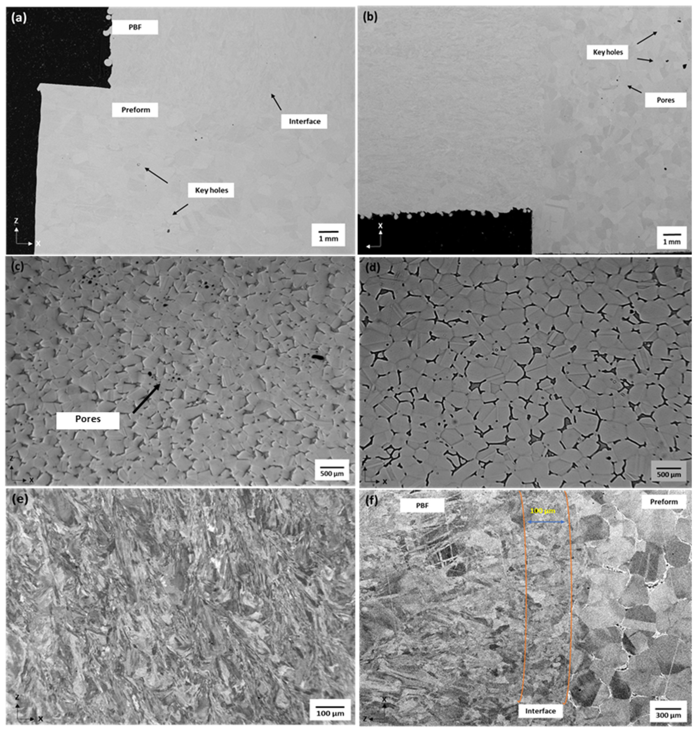
  • Metallographic analysis was performed on hybrid samples to assess their microstructural integrity. Samples were mechanically polished, using standard silicon carbide grinding paper, diamond suspension, and a final step employing a 50 nm colloidal silica solution. The polished samples were etched using a reagent of alcoholic FeCl solution to reveal the microstructure. Microstructural characterisation of the hybrid components and their defects analysis were performed using scanning electron microscopy (SEM), JOEL 7000 with a backscatter detector (BSE), and 5 V and 13 nA. The optical microscopy equipment was employed to detect defects and examine the weld successions without performing any destructive tests. Moreover, EDS was employed to evaluate the chemical composition of the specimens and thus to investigate the behaviour of the post treated samples. The grain size of the MIM and PBF sections was measured using the open-source images analysis software, ImageJ [51].
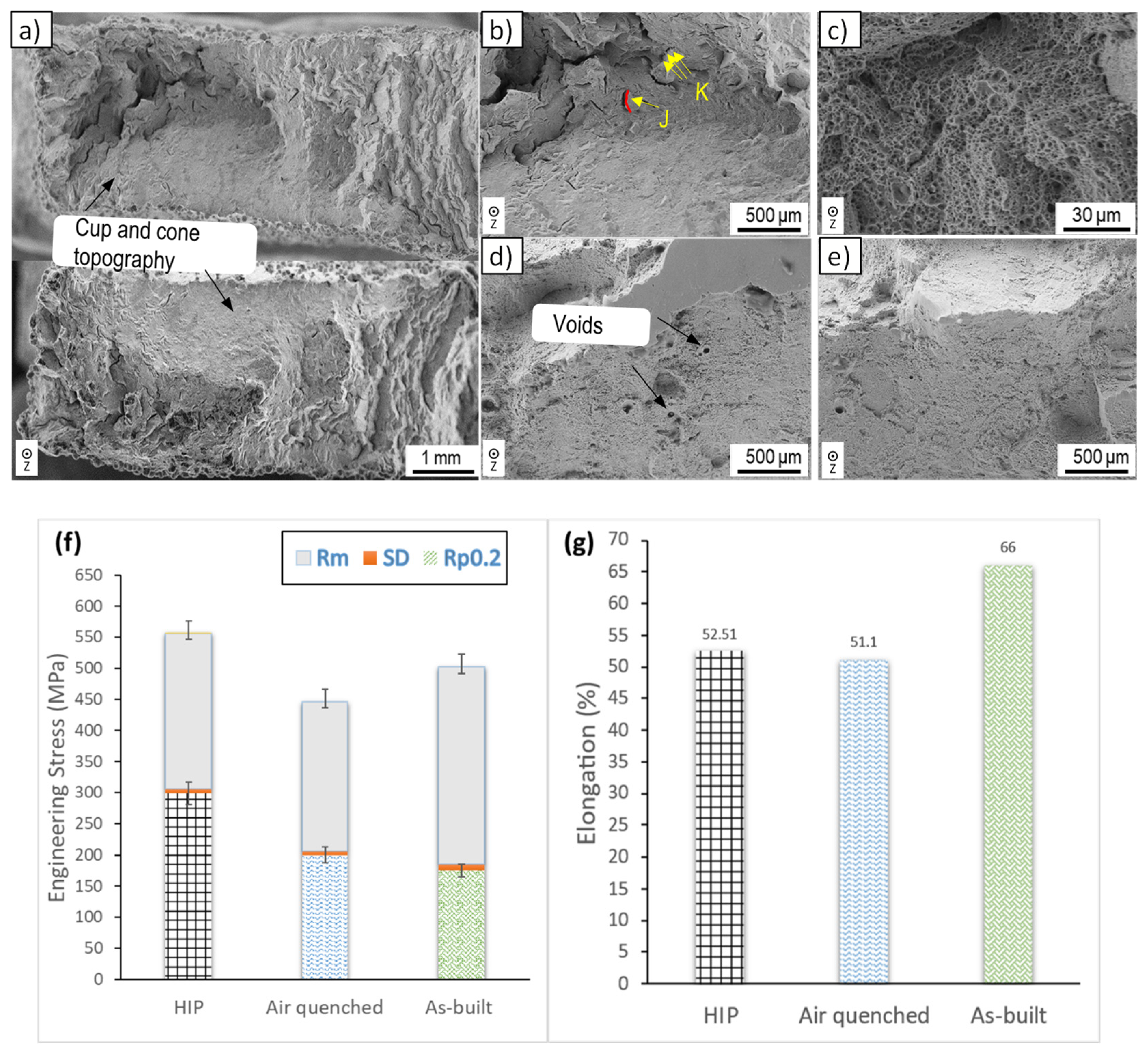
  • Tensile tests were employed to assess the structural integrity of the hybrid components. A ZwickRoell generic testing machine was used for measurements. A pre-load of 3 MPa with a constant velocity of 6 mm/min at an ambient temperature were set for all the tests, tested in accordance to BS EN ISO 6892-1-2016.
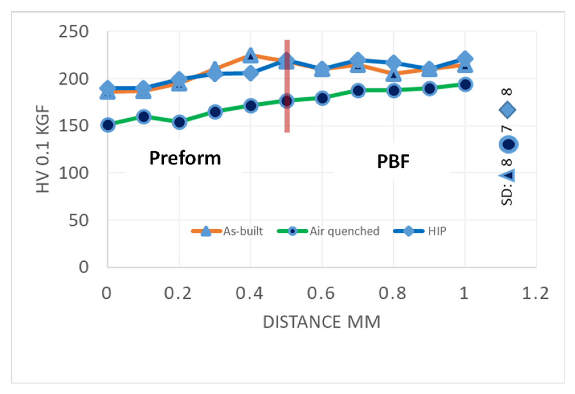
  • Micro-Hardness tests were carried out with two sets of 10 indentations on the hybrid samples with a load of 100 g and an indent time of 10 s, tested in accordance to ASTM E384. The measurements were recorded and subsequently used to assess the impact of the post treatments.
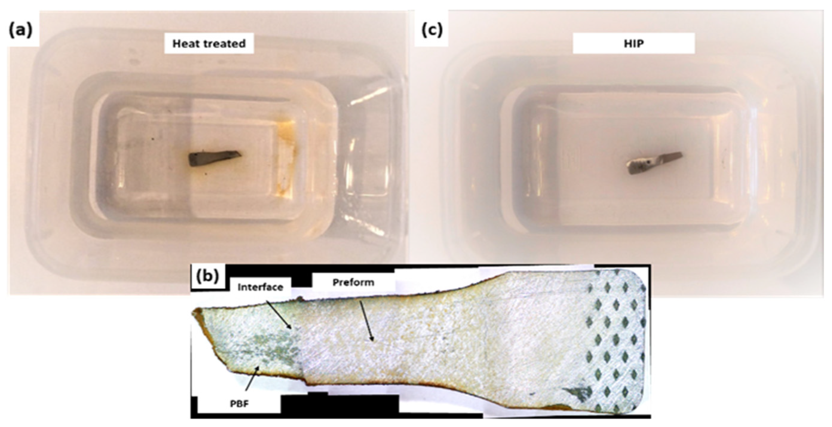
  • Corrosion resistance standard test method ASTM B895, for stainless steel powder metallurgy parts, by immersion in a sodium chloride solution consisting of 5% NaCl at 21 ± 1 °C, was employed to evaluate the corrosion resistance of the hybrid parts.

3. Results and Discussion

3.1. Microstructure Analysis

Spherical pores were observed in the MIM preforms (porosity 0.06%) and L-PBF section (porosity 0.01%) of as-built samples, whilst the heat treatment densified the L-PBF structure and led to further porosity free composition (porosity < 0.003%), Figure 2a,b. This is additional evidence that HT cycles are a necessary post-processing step to minimize any microstructural inhomogeneity of L-PBF components [52]. However, it had a negative impact on the MIM preforms as it introduced larger pores, and some damage was observed in Figure 2b,c, probably due to the expansion and release of entrapped gasses and/or residual binders from the bulk during the HT cycle. The pore sizes were assessed using a threshold method through the ImageJ software and they were approximately 40% larger when compared with those in the as-built hybrid sample. Such residues are retained in the MIM components even after the multiple stages of the sintering process, and they often occur due to the short dwell time, incorrect temperatures in the furnaces or ramp temperature [49]. At the same time, the HIP treatment led to almost pore and defect free microstructure (porosity < 0.004%) as can be seen in Figure 2d, which could be explained with the grain growth and some pore migration towards the grain boundaries of the MIM preform.
An example of pore segregation within the final consolidation after the heat treatment and HIP cycles is shown in Figure 2c,d. In particular, after the HT cycle the microstructure in the MIM preform did not demonstrate any grain growth, while, there is an increased number of voids, even along the grain boundaries as shown in Figure 2c. Conversely, the post HIP image depicts defects free microstructure with equiaxed grains and without any voids coalescence. This shows the combined effects of high pressure and temperature that have led to an improvement of the microstructure by increasing the material density through the induction of pore shrinkage and the accelerated material diffusion [39]. Regarding the L-PBF section, a blend of columnar and equiaxed grains can be seen in Figure 2e. The elongated columnar grains in the PBF section are common for the laser processed materials and are mainly due to the epitaxy growth between the deposited layers, resulting from the rapid solidification process of the melt pool in the—Z direction [34]. In addition, it can be stated that there were no porosity and signs of cracks near the interface in all three sets of samples. The analysis of the MIM/L-PBF interface in Figure 2f shows that there have been a microstructural assimilation and grain refinement in the deposited (L-PBF) section and also in the re-melt area (~100 μm) of the MIM preforms. No grain growth occurred at the fusion line (interface) or within the heat affected zone due to the thermodynamic stability of the prior coarser grains of the preform, in all three sets. Both, the deposited material and the heat affected zone below the interface have the same fine microstructure that can be explained with the rapid solidification rates [53]. The microstructure of HIP samples revealed to be austenitic and this was further supported from the location of nickel mass fraction within grains compared to that of air-quenched samples as shown in Table 1. This is further supported, as austenitic twins can be seen in Figure 2d. Such twinning is known to form as a result of recrystallisation during HIP. The higher pressure in combination with temperature during HIP can induce the formation of high-density dislocations. When the recrystallization temperature is achieved, new recrystallised grains are formed with the presence of annealing twins [54]. Conventional HT cannot induce such dislocation density due to lack of pressure and short dwelling time, therefore the mechanism of stimulating the twinning is missing. The molybdenum (Mo) content was dissolved after the air-quenching, which is vital for the corrosion resistance in acidic or halogen ions environments, hence, undermining the good properties of the material. It is not clear though why HT reduced the Mo content to 0% and further analysis is required.

3.2. Mechanical Properties

The tensile tests were performed to investigate the mechanical properties of the hybrid MIM/L-PBF samples in the three sets, i.e., as-built and after air-quenching and HIP. The results for the as-built and air-quenched samples were used as a reference to compare them with those obtained after the HIP treatment, and thus to determine the effects on the strength and ductility of the hybrid MIM/L-PBF components. Furthermore, fracture surfaces and locations were also investigated to determine the mode of failure and to consider the point of weakness within the hybrid samples.
The fracture of the hybrid tensile specimens occurred as a result of the reduced cross section of the tensile samples at the PBF sections, for all sets of samples. This is attributed to the vertical build orientation of the PBF section and to the high UTS of the preforms, and conforms to the reported results [19,55]. In particular, the microstructure of the MIM was optimised after the HIP treatment, as a result of the pore shrinkage and consequently led to an enhanced performance. The PBF sections, were built vertically and thus are more susceptible to failures due to the build orientation which is parallel to the applied tensile loads, compared to the MIM preforms that were built horizontally, therefore any defects at the weld successions were parallel to cracks and thus prone to crack propagations. The HIP samples failed in a reduced cross section manner which developed to the typical slant fracture. The fractographic analysis of the HIP sample is provided in Figure 3a–c. The fracture topography shows a disjoint surface texture, while magnified SEM images in Figure 3b,c, revealed a cone and cup topography with some shear fracture planes together with some dimples and/or micro voids. In particular, Figure 3b indicates a large number of voids coalescence and thus their coalescence demonstrates void-covered intergranular fracture (J), together with microductilities (K) which are attributed to be formed due to tensile deformation. Notably, there is no evidence of growth of transgranular micro cracks and their nucleation on the facets that could eventually develop into macrocracks and ultimately lead to a brittle fracture. The fractography in Figure 3d,e revealed pores and micro voids coalescence on the fracture surface for both air-quench and as-built conditions. Entrapped gas pores were visible on the fractured topography for the as-built sample, whilst residues due to the expansion and release of entrapped gases and/or heterogeneities from the bulk during the HT cycle were visible on the fracture surface for the air-quench condition.
Figure 3f,g shows bar charts of ultimate strain and 0.2% offset yield strength (Rp0.2)/ultimate tensile strength (Rm), respectively obtained for the three investigated sets of samples. Rp0.2, Rm, and elongation (A) of as-built samples were 178 ± 26 MPa, 506 ± 25 MPa, and 66 ± 7%, respectively. The air-quenching led to an increase of Rp0.2 by 13%, whilst Rm and A decreased by 11 and 23% (205 ± 20 MPa, 449 ± 6 MPa, and 51 ± 1%), respectively. This could be due to the reduction of dislocations after the HT and the significantly high porosity in the material [56,57]. Conversely, the HIP treatment led to a bigger Rp0.2 increase of 68% (299 ± 20 MPa), while Rm increased by 11% (560 ± 6 MPa). At the same time, a decrease from 66 to ~53%. The A values were lower compared to the as-built samples and this can be explained with the possible formation of brittle phases during the densification. Particularly, the air trapped inside the closed pores is released to the pore walls during the pore shrinkage due to the high pressure over the HIP process and thus oxides or other phases can be initiated [58]. Nevertheless, the absence of interface failure in the air-quenched and HIP samples demonstrated a robust joint strength and revealed that both posts were properly selected. Fracture surfaces of the samples revealed signs of ductile failures (see Figure 3a–c), while Rp0.2, Rm, and A for the air-quenched samples were lower compared to the results achieved after the HIP treatment. The lower strength values could be attributed to (a) reduction of dislocation density, after the HT and (b) the σ phase precipitation, which is known to decrease the toughness and/or elongation and thus introduces embrittlement. According to the literature, there are methodologies to predict the σ phase, based on the chemical composition of the samples [59]. In particular, the results in Table 1 were elaborated and an empirical formula was employed to examine the precipitation behaviour of the σ phase, as expressed in Equation (1):
Ratio Factor (Rf) = (%Cr − 16%C)/%Ni
As stated by other researchers, if Rf is higher than 1.7, the σ phase can precipitate in stainless steel [59]. Therefore, there is a higher probability of the σ phase precipitation in the air-quenched sample since Rf is higher than 1.7, i.e., 2.21. Regarding the HIP samples, Rf is 0.63 and thus this is another evidence supporting the results obtained with the metallurgical analysis that revealed the σ phase precipitation tendency for all three sets of samples.
The tests revealed that the HIP samples were superior to their as-built and conventionally heat treated counterparts in regards to their strength. Their higher Rp0.2 values (~300 MPa) can be explained with the minimised porosity (see Figure 2), the dislocation density movement within the lattice and also the deformation and recrystallisation which is facilitated by high temperature and higher pressure in HIP [60]. The results of the tensile tests also bare a good comparison with those reported in the literature and also matching the values reported for non-irradiated room temperature tensile tests [61,62,63].

3.3. Micro-Hardness Measurements

Ten Vickers micro-hardness measurements with 100 g weight along 1 mm line were taken at the interface line between the MIM preform and the L-PBF section of the three sets of samples and are presented in Figure 4. In the case of as-built bars, there was an increase of the hardness across the MIM/L-PBF interface, which is mainly due to the lack of porosity at the interface and the high dislocation density at the sub-grains boundaries which is typical for the as-built 316 L material [56]. Concurrently, the heat treatment reduced the hardness of the samples and this was in line with the obtained results on air-quenched samples. The relatively low hardness values for the air-quenched samples, can be associated with a residual stress relief and their porosity. Which in the case of the MIM preform, the hardness was even lower due to the porosity, which was introduced in the preform after the HT [64,65]. Furthermore, the conventional HT led to a homogenisation of the hardness over the interface of hybrid samples and this could mainly be due to the refined microstructure at the fusion line (interface), and the recovery (reduction in dislocation density induced during the specific HT regime) [48]. Conversely, the hardness increased marginally for the HIP hybrid samples. This increase can be explained with the strain hardening that is particularly high on plastically deformed sections of the L-PBF built at the first few L-PBF layers, in combination with the elevated temperature and pressure during the post treatment that minimised porosity through the hybrid sample. In particular, the hardness increase there, was significant compared to the MIM preforms and this could be attributed to the applied heat load during the L-PBF process, the redistribution of dislocation density within the microstructure, and also the deformation and recrystallisation which is facilitated by higher pressure and temperature induced during the HIP process [60]. Overall, the small alternations of hardness at the interface indicates a strong bonding between the preform and L-PBF sections [64]. This conforms well to the results from the tensile tests, as all samples showed a ductile fracture at the L-PBF sections and no samples demonstrated a fracture at the interface or near the interface area.

3.4. Corrosion Resistance Measurements

For the evaluation of the corrosion resistance of the hybrid specimens, the ASTM B895 standard test was employed. Hybrid samples from each condition were evaluated i.e., as-built, heat treated, and HIP. All the samples were polished with 120 grit paper, followed by degreasing and cleaning with acetone and deionised water, the samples were dried in air prior to being tested. Immediately, before testing they were weighed and assigned a testing tray. The samples were kept in the solution for up to 90 h. As presented in Figure 5a,b, the conventionally heat treated sample demonstrated some corrosion within 36 h in the solution and this was attributed to the lack of Mo, which is reported to have a substantial role in the corrosion resistivity of stainless steel [66]. Conversely, the HIP ones showed corrosion resistance, even after 36 h and this is attributed to the retention of Mo concentration and the lack of pores in the structure that enhance the corrosion resistivity of the material, Figure 5c. The as-built sample did not show any signs of corrosion even after 90 h in the solution, and this is consistent with other studies [56]. All specimens were weighed again after they were removed from their respective testing trays, although, the weight change was negligible ~0.1 g.

4. Application Areas of Hybrid 316 L Stainless Steel

The effects of the HIP treatments on MIM and L-PBF components have already been studied thoroughly and also they are well reported in the literature. As it was demonstrated in Section 3, HIP has favourable effects on microstructure, mechanical properties, and surface integrity of hybrid components. In particular, the 316 L SS key properties, i.e., strength and corrosion resistance, were retained and enhanced further through the HIP treatment and thus to tailor the properties of the hybrid components and make them suitable for several applications. 316 L SS is a very well-known biomaterial for hip and knee replacement, due to its high strength, corrosion and wear resistance, and beneficial cell proliferation that can be subsequently enhanced through various coating techniques [9,67,68]. It has been reported that in non-HIP samples, exposed pores can hold contaminants that can leave defects during plating and harbour bacteria in medical applications. Therefore, HIP treatments are successful at enhancing the cleanliness and better polishing results can be achieved on processed surfaces, and thus to improve the surface integrity of components [27,28]. Furthermore, steels especially SS are widely used in the aerospace sector to produce engine and/or exhaust components, due to their superior high temperature tolerances and their good corrosion resistance. In addition, they are used to produce fasteners and landing gear equipment due to the material’s high tensile strength and shear modulus that enhance their damping capacity and make them ideal for absorbing stresses during their service life, as well as to ensure a longer lifespan of the components whilst supressing/minimising fatigue failures. In this context, the HCM technology can efficiently be deployed together with the HIP treatment to substantially enhance the hybrid components properties, especially by improving their durability, retaining the initial good properties of the materials, and minimising any risks of failure during their service life [69,70]. Overall, HCM in combination with the HIP treatment can deliver sound improvements in both the performance and components’ lifespan in medical, safety critical applications, and in other applications requiring high performance.

5. Conclusions

In this research, HT methods for hybrid components were investigated, especially their impact on the microstructure and mechanical strength of hybrid MIM/PBF 316L components. A special HIP treatment was investigated for overcoming slack microstructures and incompatibilities between MIM and L-PBF processes when producing hybrid components. The HIP treatment allows the HCM process to produce hybrid components with tailored and consistent mechanical and chemical properties to meet the technical requirements of end use applications. Based on the obtained experimental results, the following conclusions were made:
  • Conventional HT, such as air-quenching was found to introduce a brittle phase precipitation in hybrid components. Therefore, air-quenching impairs the hybrid components’ strength by decreasing the elongation and especially their UTS below the materials standards.
  • High pressure in combination with higher temperatures reduce porosity in the MIM preforms, in contrast to conventional HT which enlarges the pores significantly compared to the primary microstructure. Thus, minimising and eliminating defects and porosity accumulation, due to gas and residues expansion.
  • The 316 L air-quenched samples were found to have no molybdenum content and moreover, showed a lower corrosion resistance compared to the HIP samples. In particular, the HIP treatment led to a greater pitting resistance, while demonstrating a retention of the high Mo concentration (wt ~3%) and thus making HIP samples suitable for corrosive environments.
  • The HIP treatment was found to increase the hybrid components’ strength compared to as-built ones by ~68 and ~11% in YS and UTS, respectively. These mechanical properties improvements were attributed to the further densification of the lattice, the reduced inherent defects and diffusions compared to the primary or air-quenched microstructure.
  • Another beneficial effect of the HIP treatment was the resulting equiaxed grains that removed any heterogeneities and minimised any porosity in the bulk, whilst maintaining a ductility rate higher to that of air-quenched hybrid components.
  • The HIP treatment reduced the probability of brittle fracture or premature failure with the deformation and recrystallization within the lattice, due to the applied high temperature and pressure. As a result of the higher temperature and pressure, both sections of the hybrid components benefit from the minimised porosity, leading to a higher interface quality and consequently superior strength of the hybrid parts that conform to the results reported in the literature.
The research showed clearly that the HIP treatments of hybrid components can address some significant shortfalls of the HCM process when combined with traditional heat treatments and thus, to meet the technical requirements for a range of applications. This can be achieved by applying a well-known and proven functional treatment.

Author Contributions

Conceptualization, A.M.; methodology, A.M.; validation, A.M. and D.L.; investigation; formal analysis, A.M. and A.M.; resources, A.M., J.M., D.V. and P.P.; writing—original draft preparation, A.M.; writing—review and editing, A.M., D.L. and R.M.R.; visualization, A.M.; supervision, S.D., K.E. and D.I.W.; funding acquisition, S.D. and D.I.W. All authors have read and agreed to the published version of the manuscript.

Funding

This research was funded from the European Union’s Horizon 2020 research and innovation programme, under grant agreement no. 723826 MAESTRO.

Institutional Review Board Statement

Not applicable.

Informed Consent Statement

Not applicable.

Data Availability Statement

Not applicable.

Acknowledgments

The authors would like to thank the Manufacturing Technology Centre (MTC) for the financial support of Aldi Mehmeti’s PhD research.

Conflicts of Interest

The authors declare no conflict of interest.

References

  1. Murr, L.E. Metallurgy principles applied to powder bed fusion 3D printing/additive manufacturing of personalized and optimized metal and alloy biomedical implants: An overview. J. Mater. Res. Technol. 2020, 9, 1087–1103. [Google Scholar] [CrossRef]
  2. Nichols, M.R. How does the automotive industry benefit from 3D metal printing? Met. Powder Rep. 2019, 74, 257–258. [Google Scholar] [CrossRef]
  3. Du, W.; Bai, Q.; Zhang, B. A Novel Method for Additive/Subtractive Hybrid Manufacturing of Metallic Parts. Procedia Manuf. 2016, 5, 1018–1030. [Google Scholar] [CrossRef] [Green Version]
  4. Polotski, V.; Kenne, J.P.; Gharbi, A. Production and setup policy optimization for hybrid manufacturing–remanufacturing systems. Int. J. Prod. Econ. 2017, 183, 322–333. [Google Scholar] [CrossRef]
  5. Carroll, B.E.; Palmer, T.A.; Beese, A.M. Anisotropic tensile behavior of Ti-6Al-4V components fabricated with directed energy deposition additive manufacturing. Acta Mater. 2015, 87, 309–320. [Google Scholar] [CrossRef]
  6. Hrabe, N.; Gnäupel-Herold, T.; Quinn, T. Fatigue properties of a titanium alloy (Ti-6Al-4V) fabricated via electron beam melting (EBM): Effects of internal defects and residual stress. Int. J. Fatigue 2017, 94, 202–210. [Google Scholar] [CrossRef] [Green Version]
  7. Denny, J.; Jinoop, A.N.; Paul, C.P.; Singh, R.; Bindra, K.S. Fatigue Crack Propagation Behaviour of Inconel 718 Structures Built using Directed Energy Deposition based Laser Additive Manufacturing. Mater. Lett. 2020, 276, 128241. [Google Scholar] [CrossRef]
  8. Sabzi, H.E.; Maeng, S.; Liang, X.; Simonelli, M.; Aboulkhair, N.T.; Rivera-Díaz-del-Castillo, P.E.J. Controlling crack formation and porosity in laser powder bed fusion: Alloy design and process optimisation. Addit. Manuf. 2020, 34, 101360. [Google Scholar] [CrossRef]
  9. Essa, K.; Jamshidi, P.; Zou, J.; Attallah, M.M.; Hassanin, H. Porosity control in 316L stainless steel using cold and hot isostatic pressing. Mater. Des. 2018, 138, 21–29. [Google Scholar] [CrossRef] [Green Version]
  10. Bhaduri, D.; Penchev, P.; Dimov, S.; Essa, K.; Carter, L.N.; Pruncu, C.I.; Jiang, J.; Pullini, D. On the surface integrity of additive manufactured and post-processed AlSi10Mg parts. Procedia CIRP 2020, 87, 339–344. [Google Scholar] [CrossRef]
  11. Benzing, J.; Hrabe, N.; Quinn, T.; White, R.; Rentz, R.; Ahlfors, M. Hot isostatic pressing (HIP) to achieve isotropic microstructure and retain as-built strength in an additive manufacturing titanium alloy (Ti-6Al-4V). Mater. Lett. 2019, 257, 126690. [Google Scholar] [CrossRef]
  12. de Formanoir, C.; Michotte, S.; Rigo, O.; Germain, L.; Godet, S. Electron beam melted Ti-6Al-4V: Microstructure, texture and mechanical behavior of the as-built and heat-treated material. Mater. Sci. Eng. A 2016, 652, 105–119. [Google Scholar] [CrossRef]
  13. Wang, Y.; Shi, J. Effect of hot isostatic pressing on nanoparticles reinforced AlSi10Mg produced by selective laser melting. Mater. Sci. Eng. A 2020, 788, 139570. [Google Scholar] [CrossRef]
  14. Dehghan-Manshadi, A.; Yu, P.; Dargusch, M.; StJohn, D.; Qian, M. Metal injection moulding of surgical tools, biomaterials and medical devices: A review. Powder Technol. 2020, 364, 189–204. [Google Scholar] [CrossRef]
  15. Goenka, M.; Nihal, C.; Ramanathan, R.; Gupta, P.; Parashar, A.; Joel, J. Automobile Parts Casting-Methods and Materials Used: A Review. Mater. Today Proc. 2019, 22, 2525–2531. [Google Scholar] [CrossRef]
  16. Fiorentini, F.; Curcio, P.; Armentani, E.; Rosso, C.; Baldissera, P. Study of two alternative cooling systems of a mold insert used in die casting process of light alloy components. Procedia Struct. Integr. 2019, 24, 569–582. [Google Scholar] [CrossRef]
  17. Penchev, P.; Bhaduri, D.; Carter, L.; Mehmeti, A.; Essa, K.; Dimov, S.; Adkins, N.J.E.; Maillol, N.; Bajolet, J.; Maurath, J.; et al. System-level integration tools for laser-based powder bed fusion enabled process chains. J. Manuf. Syst. 2019, 50, 87–102. [Google Scholar] [CrossRef]
  18. Makris, S.; Aivaliotis, P. Framework for accurate simulation and model-based control of hybrid manufacturing processes. Procedia CIRP 2020, 97, 470–475. [Google Scholar] [CrossRef]
  19. Mehmeti, A.; Penchev, P.; Lynch, D.; Vincent, D.; Maillol, N.; Maurath, J.; Bajolet, J.; Wimpenny, D.I.; Essa, K.; Dimov, S. Mechanical behaviour and interface evaluation of hybrid MIM/PBF stainless steel components. Rapid Prototyp. J. 2020, 26, 1809–1825. [Google Scholar] [CrossRef]
  20. Reichler, A.K.; Gerbers, R.; Falkenberg, P.; Türk, E.; Dietrich, F.; Vietor, T.; Dröder, K. Incremental Manufacturing: Model-based part design and process planning for Hybrid Manufacturing of multi-material parts. Procedia CIRP 2019, 79, 107–112. [Google Scholar] [CrossRef]
  21. Chen, L.; Lau, T.Y.; Tang, K. Manufacturability analysis and process planning for additive and subtractive hybrid manufacturing of Quasi-rotational parts with columnar features. CAD Comput. Aided Des. 2020, 118, 102759. [Google Scholar] [CrossRef]
  22. Rossi, A.; Lanzetta, M. Integration of hybrid additive/subtractive manufacturing planning and scheduling by metaheuristics. Comput. Ind. Eng. 2020, 144, 106428. [Google Scholar] [CrossRef]
  23. Chinnathai, M.K.; Al-Mowafy, Z.; Alkan, B.; Vera, D.; Harrison, R. A framework for pilot line scale-up using digital manufacturing. Procedia CIRP 2019, 81, 962–967. [Google Scholar] [CrossRef]
  24. Bhaduri, D.; Penchev, P.; Dimov, S.; Essa, K.; Carter, L.N.; Pruncu, C.I.; Pullini, D. Evaluation of surface/interface quality, microstructure and mechanical properties of hybrid additive-subtractive aluminium parts. CIRP Ann. 2019, 68, 237–240. [Google Scholar] [CrossRef]
  25. Spierings, A.B.; Starr, T.L.; Wegener, K. Fatigue performance of additive manufactured metallic parts. Rapid Prototyp. J. 2013, 19, 88–94. [Google Scholar] [CrossRef]
  26. Zheng, Y.; Liu, J.; Ahmad, R. A cost-driven process planning method for hybrid additive–subtractive remanufacturing. J. Manuf. Syst. 2020, 55, 248–263. [Google Scholar] [CrossRef]
  27. Chen, N.; Frank, M. Process planning for hybrid additive and subtractive manufacturing to integrate machining and directed energy deposition. Procedia Manuf. 2019, 34, 205–213. [Google Scholar] [CrossRef]
  28. Bambach, M.; Sizova, I.; Sydow, B.; Hemes, S.; Meiners, F. Hybrid manufacturing of components from Ti-6Al-4V by metal forming and wire-arc additive manufacturing. J. Mater. Process. Technol. 2020, 282, 116689. [Google Scholar] [CrossRef]
  29. Flodin, A.; Andersson, M.; Miedzinski, A. Full density powder metal components through Hot Isostatic Pressing. Met. Powder Rep. 2017, 72, 107–110. [Google Scholar] [CrossRef]
  30. Herrmann, M.; Räthel, J. Hot Pressing and Hot Isostatic Pressing. In Encyclopedia of Materials: Technical Ceramics and Glasses; Pomeroy, M., Ed.; Elsevier: San Diego, CA, USA, 2021; pp. 270–277. [Google Scholar]
  31. Wang, X.; Carter, L.N.; Adkins, N.J.E.; Essa, K.; Attallah, M.M. Novel hybrid manufacturing process of CM247LC and multi-material blisks. Micromachines 2020, 11, 492. [Google Scholar] [CrossRef]
  32. Romero, A.; Morales, A.L.; Herranz, G. Enhancing Properties of Soft Magnetic Materials: A Study into Hot Isostatic Pressing and Sintering Atmosphere Influences. Metals 2021, 11, 643. [Google Scholar] [CrossRef]
  33. Heaney, D.F.; Binet, C. Hot isostatic pressing (HIP) of metal injection molding (MIM). In Handbook of Metal Injection Molding; Heaney, D.F., Ed.; Woodhead Publishing: Cambridge, UK, 2019; pp. 195–202. [Google Scholar]
  34. Carter, L.N.; Martin, C.; Withers, P.J.; Attallah, M.M. The influence of the laser scan strategy on grain structure and cracking behaviour in SLM powder-bed fabricated nickel superalloy. J. Alloys Compd. 2014, 615, 338–347. [Google Scholar] [CrossRef]
  35. Hassanin, H.; Al-Kinani, A.A.; Elshaer, A.; Polycarpou, E.; El-Sayed, M.A.; Essa, K. Stainless steel with tailored porosity using canister-free hot isostatic pressing for improved osseointegration implants. J. Mater. Chem. B 2017, 5, 9384–9394. [Google Scholar] [CrossRef] [Green Version]
  36. Bocanegra-Bernal, M.H.; Domínguez-Rios, C.; Garcia-Reyes, A.; Aguilar-Elguezabal, A.; Echeberria, J.; Nevarez-Rascon, A. Hot isostatic pressing (HIP) of α-Al2O3 submicron ceramics pressureless sintered at different temperatures: Improvement in mechanical properties for use in total hip arthroplasty (THA). Int. J. Refract. Met. Hard Mater. 2009, 27, 900–906. [Google Scholar] [CrossRef]
  37. Sun, X.; Liu, D.; Chen, M.; Zhou, W.; Nomura, N.; Hanawa, T. Hot isostatic pressing of MRI compatible Zr-1Mo components manufactured by laser powder bed fusion. Mater. Charact. 2020, 169, 110657. [Google Scholar] [CrossRef]
  38. Sreenu, B.; Sarkar, R.; Kumar, S.S.S.; Chatterjee, S.; Rao, G.A. Microstructure and mechanical behaviour of an advanced powder metallurgy nickel base superalloy processed through hot isostatic pressing route for aerospace applications. Mater. Sci. Eng. A 2020, 797, 140254. [Google Scholar] [CrossRef]
  39. Khomutov, M.; Potapkin, P.; Cheverikin, V.; Petrovskiy, P.; Travyanov, A.; Logachev, I.; SovaI, A.; Smurov, I. Effect of hot isostatic pressing on structure and properties of intermetallic NiAl–Cr–Mo alloy produced by selective laser melting. Intermetallics 2020, 120, 106766. [Google Scholar] [CrossRef]
  40. Cai, C.; Gao, X.; Teng, Q.; Kiran, R.; Liu, J.; Wei, Q.; Shi, Y. Hot isostatic pressing of a near α-Ti alloy: Temperature optimization, microstructural evolution and mechanical performance evaluation. Mater. Sci. Eng. A 2020, 802, 140426. [Google Scholar] [CrossRef]
  41. Todd, I.; Sidambe Dr, A.T. Developments in metal injection moulding (MIM). In Advances in Powder Metallurgy: Properties, Processing and Applications; Chang, I., Zhao, Y., Eds.; Woodhead Publishing: Cambridge, UK, 2013; Volume 1, pp. 109–146. [Google Scholar]
  42. MIMplus Technologies GmbH & Co. KG|Deutschland. Available online: https://www.mimplus.com/ (accessed on 12 April 2019).
  43. Ebenhovh, J.S. Catalytic gas phase erosion for the rapid debinding of metal injection moulded (MIM) green parts. Met. Powder Rep. 1991, 46, 58. [Google Scholar]
  44. Moon, I.-H.; Kim, J.-C.; Suk, M.-J. Cold isostatic pressing of brown MIM parts. Met. Powder Rep. 1996, 51, 45. [Google Scholar]
  45. Zhao, M.; Qiao, L.; Zheng, J.; Ying, Y.; Yu, J.; Li, W.; Che, S. Investigation of the solvent debinding in the injection molding of ZrO2 ceramics using LDEP, HDPE and wax binders. Ceram. Int. 2019, 45, 3894–3901. [Google Scholar] [CrossRef]
  46. Albrecht, D.; Möhring, H.-C. Potentials for the optimization of sawing processes using the example of bandsawing machines. Procedia Manuf. 2018, 21, 567–574. [Google Scholar] [CrossRef]
  47. Ibrahim, O.H.; Ibrahim, I.S.; Khalifa, T.A.F. Effect of aging on the toughness of austenitic and duplex stainless steel weldments. J. Mater. Sci. Technol. 2010, 26, 810–816. [Google Scholar] [CrossRef]
  48. Ronneberg, T.; Davies, C.M.; Hooper, P.A. Revealing relationships between porosity, microstructure and mechanical properties of laser powder bed fusion 316L stainless steel through heat treatment. Mater. Des. 2020, 189, 108481. [Google Scholar] [CrossRef]
  49. Banerjee, S.; Joens, C.J. Debinding and sintering of metal injection molding (MIM) components. In Handbook of Metal Injection Molding; Heaney, F.D., Ed.; Elsevier: Amsterdam, The Netherlands, 2019; Volume 2, pp. 129–171. [Google Scholar]
  50. Elangeswaran, C.; Cutolo, A.; Muralidharan, G.K.; Vanmeensel, K.; Van Hooreweder, B. Microstructural analysis and fatigue crack initiation modelling of additively manufactured 316L after different heat treatments. Mater. Des. 2020, 194, 108962. [Google Scholar] [CrossRef]
  51. ImageJ. Available online: https://imagej.nih.gov/ij/ (accessed on 4 August 2021).
  52. Gou, J.; Shen, J.; Hu, S.; Tian, Y.; Liang, Y. Microstructure and mechanical properties of as-built and heat-treated Ti-6Al-4V alloy prepared by cold metal transfer additive manufacturing. J. Manuf. Process. 2019, 42, 41–50. [Google Scholar] [CrossRef]
  53. Wang, T.; Zhu, Y.Y.; Zhang, S.Q.; Tang, H.B.; Wang, H.M. Grain morphology evolution behavior of titanium alloy components during laser melting deposition additive manufacturing. J. Alloys Compd. 2015, 632, 505–513. [Google Scholar] [CrossRef]
  54. Irukuvarghula, S.; Hassanin, H.; Cayron, C.; Attallah, M.M.; Stewart, D.; Preuss, M. Evolution of grain boundary network topology in 316L austenitic stainless steel during powder hot isostatic pressing. Acta Mater. 2017, 133, 269–281. [Google Scholar] [CrossRef]
  55. Castro, L.; Merino, S.; Levenfeld, B.; Várez, A.; Torralba, J.M. Mechanical properties and pitting corrosion behaviour of 316L stainless steel parts obtained by a modified metal injection moulding process. J. Mater. Process. Technol. 2003, 143–144, 397–402. [Google Scholar] [CrossRef]
  56. Kong, D.; Dong, C.; Ni, X.; Zhang, L.; Yao, J.; Man, C.; Cheng, X.; Xiao, K.; Li, X. Mechanical properties and corrosion behavior of selective laser melted 316L stainless steel after different heat treatment processes. J. Mater. Sci. Technol. 2019, 35, 1499–1507. [Google Scholar] [CrossRef]
  57. Tsuchida, N.; Kawahata, T.; Ishimaru, E.; Takahashi, A. Effects of temperature and strain rate on tensile properties of a lean duplex stainless steel. ISIJ Int. 2014, 54, 1971–1977. [Google Scholar] [CrossRef] [Green Version]
  58. Petrovskiy, P.; Khomutov, M.; Cheverikin, V.; Travyanov, A.; Sova, A.; Smurov, I. Influence of hot isostatic pressing on the properties of 316L stainless steel, Al-Mg-Sc-Zr alloy, titanium and Ti6Al4V cold spray deposits. Surf. Coat. Technol. 2021, 405, 126736. [Google Scholar] [CrossRef]
  59. Chih-Chun Hsieh, W.W. Overview of Intermetallic Sigma (σ) Phase Precipitation in Stainless Steels. Int. Sch. Res. Not. 2012, 201, 16. [Google Scholar]
  60. Tan, L.; He, G.; Liu, F.; Li, Y.; Jiang, L. Effects of temperature and pressure of hot isostatic pressing on the grain structure of powder metallurgy superalloy. Materials 2018, 11, 328. [Google Scholar] [CrossRef] [PubMed] [Green Version]
  61. Cegan, T.; Pagac, M.; Jurica, J.; Skotnicova, K.; Hajnys, J.; Horsak, L.; Soucek, K.; Krpec, P. Effect of hot isostatic pressing on porosity and mechanical properties of 316 l stainless steel prepared by the selective laser melting method. Materials 2020, 13, 4377. [Google Scholar] [CrossRef]
  62. Maloy, S.A.; James, M.R.; Willcutt, G.; Sommer, W.F.; Sokolov, M.; Snead, L.L.; Hamilton, M.L.; Garner, F. The mechanical properties of 316L/304L stainless steels, Alloy 718 and Mod 9Cr-1Mo after irradiation in a spallation environment. J. Nucl. Mater. 2001, 296, 119–128. [Google Scholar] [CrossRef]
  63. Lavery, N.P.; Cherry, J.; Mehmood, S.; Davies, H.; Sackett, E.; Brown, S.; Sienz, J. Effects of hot isostatic pressing on the elastic modulus and tensile properties of 316L parts made by powder bed laser fusion. Mater. Sci. Eng. A 2017, 693, 186–213. [Google Scholar] [CrossRef] [Green Version]
  64. Tan, C.; Wang, G.; Ji, L.; Tong, Y.; Duan, X.-M. Investigation on 316L/316L-50W/W plate functionally graded materials fabricated by spark plasma sintering. Fusion Eng. Des. 2017, 125, 171–177. [Google Scholar] [CrossRef]
  65. Krakhmalev, P.; Fredriksson, G.; Svensson, K.; Yadroitsev, I.; Yadroitsava, I.; Thuvander, M.; Peng, R. Microstructure, solidification texture, and thermal stability of 316 L stainless steel manufactured by laser powder bed fusion. Metals 2018, 8, 643. [Google Scholar] [CrossRef] [Green Version]
  66. Kong, D.; Ni, X.; Dong, C.; Lei, X.; Zhang, L.; Man, C.; Yao, J.; Cheng, X.; Li, X. Bio-functional and anti-corrosive 3D printing 316L stainless steel fabricated by selective laser melting. Mater. Des. 2018, 152, 88–101. [Google Scholar] [CrossRef]
  67. Li, Y.; Feng, Z.; Hao, L.; Huang, L.; Xin, C.; Wang, Y.; Bilotti, E.; Essa, K.; Zhang, H.; Li, Z.; et al. A Review on Functionally Graded Materials and Structures via Additive Manufacturing: From Multi-Scale Design to Versatile Functional Properties. Adv. Mater. Technol. 2020, 5, 1900981. [Google Scholar] [CrossRef]
  68. Lamichhane, Y.; Singh, G.; Bhui, A.S.; Mukhiya, P.; Kumar, P.; Thapa, B. Surface modification of 316L SS with HAp nano-particles using PMEDM for enhanced biocompatibility. Mater. Today Proc. 2019, 15, 336–343. [Google Scholar] [CrossRef]
  69. Why Stainless Steel Is Essential for the Aerospace Industry. Available online: https://www.marlinwire.com/blog/why-you-should-use-stainless-steel-for-aerospace-applications. (accessed on 25 January 2020).
  70. Zhang, X.; Chen, Y.; Hu, J. Recent advances in the development of aerospace materials. Prog. Aerosp. Sci. 2018, 97, 22–34. [Google Scholar] [CrossRef]
Figure 1. The test tensile bar. (a) Geometric dimensions [19]. (b) the produced hybrid MIM/L-PBF tensile bar.
Applsci 11 07490 g001
Figure 2. Cross sections of (a) as-built, (b,c) HT air-quenched, and (d,f) HIP samples. Arrows in (a,b) point at gas pores and keyholes. Higher magnification BSE-SEM images in (c,d) show the porosity state and grain growth, at the MIM preform in air-quenched and HIP samples, respectively. Higher magnification images (e,f) show the columnar and some equiaxed grains in the L-PBF section and the microstructural assimilation at the re-melt area/interface, respectively.
Applsci 11 07490 g002
Figure 3. Analysis of mechanical properties. (ac) A representative cup and cone fracture surface of the HIP sample showing clearly the dimples, with (K) aligned microductilities and (J) intergranular cracks; (d,e) a representative fracture surface of an air-quench and as-built sample, respectively; (f,g) bar charts with the tensile properties for the three sets of samples.
Applsci 11 07490 g003
Figure 4. The results of micro-hardness test for all three sets of samples, the red vertical bar shows the interface location; SD: Standard deviation.
Applsci 11 07490 g004
Figure 5. The results of corrosion test for the hybrid samples, (a) heat treated sample in its respective testing tray at 36 h, (b) heat treated sample with surface corrosion after 36 h, and (c) image of HIP sample right after 36 h in the solution.
Applsci 11 07490 g005
Table 1. Material composition (% by mass) before, after air quench, and the HIP treatment, averaged from the data of three samples. Values in the bracket indicate standard deviation.
Material Condition MIM
Sandvik Powder
FeCrNiMoMnCSSi
As-builtBalance17.75
(±1.73)
9.34
(±1.04)
1.37
(±0.24)
0.83
(±0.17)
0.75
(±0.61)
0.2
(±0.2)
0.10
(±0.09)
Air-quenchBalance12.86
(±0.30)
9.81
(±1.52)
0.003.60
(±0.34)
2.16
(±1.20)
0.04
(±0.08)
0.19
(±0.11)
HIPBalance17.02
(±1.31)
14.04
(±0.85)
3.15
(±0.31)
1.13
(±0.19)
0.51
(±0.50)
0.0000.72
(±0.17)
Material Condition PBF
EOS powder
As-builtBalance17.79
(±1.58)
9.33
(±1.25)
1.38
(±0.27)
0.88
(±0.18)
0.70
(±0.48)
0.2
(±0.2)
0.10
(±0.09)
Air-quenchBalance13.82
(±1.20)
10.55
(±1.03)
0.003.87
(±0.41)
2.32
(±1.24)
0.005
(±0.08)
0.2
(±0.11)
HIPBalance16.65
(±1.53)
13.73
(±1.40)
3.08
(±0.42)
1.11
(±0.20)
0.50
(±0.51)
0.0000.36
(±0.14)
Publisher’s Note: MDPI stays neutral with regard to jurisdictional claims in published maps and institutional affiliations.

