1. Introduction
Automatic assembly is an important part of an industrial automation system. The robot, due to its high flexibility, plays a key role in the fully automatic assembly system. However, in a typical assembly task, the workpieces have to contact each other in order to accomplish the mating process. Therefore, different from material handling, welding or spraying tasks, the robotic assembly not only requires precisely controlling the robot position but also needs to regulate the contact force compliantly and safely. Therefore, complex hybrid control policies have to be designed according to different configurations.
Peg-in-hole is one of the most common operations in assembly applications. Because of the limitations on the robot repeatability, fixturing and grabbing errors, the tight tolerant peg-in-hole task used to be a difficult task [
1]. Without compliant control policy, the initial errors may generate huge reaction force, which may damage the robot or workpieces. Without a sophisticated control policy, the success rate will be low for large variation scenarios.
Passive compliance and active compliance are two ways to implement the compliance peg-in-hole operation. The passive compliance uses a flexible device like a rubber spring to link the end effector and gripper. The error will be compensated by the device’s deformation [
1,
2,
3]. However, the passive compliance device is not generally applicable and has to be redesigned according to different task configurations. With the development of force sensors, the active force control is more and more used in many applications. The force sensor is installed at the end effector to detect the contact force. This force information is then regarded as the feedback for the close loop control system. The controller regulates the posture/force/impendence parameters to reduce the contact force and realize the compliance behavior [
4,
5].
According to the shape of the peg, the tasks can be classified into cylinder peg-in-hole assembly and irregular shaped peg-in-hole assembly [
6]. According to the number of pegs, it can be classified into single peg-in-hole and multiple peg-in-hole tasks [
7]. According to the stages of the peg, it can be classified into single stage peg-in-hole and cascaded peg-in-hole assembly [
8].
Most studies focus on cylinder peg-in-hole tasks. Error compensation and search-insertion strategies are widely used to accommodate peg position and rotation errors. Spiral, circular, or line search patterns are commonly used to efficiently search for the real hole position. For irregular shaped peg-in-hole tasks, such as square peg and key-slot assembly, the above 2DOF search method becomes inefficient because the search space changes from 2 to 3.
There are two categories of peg-in-hole assembly strategies: model-based and model-free methods [
9]. Model-based methods use a prebuilt force/geometric model to map the force measurement to geometric errors and then use this prediction to compensate for the part position/posture errors. Some papers use the exact mathematic model to find the properly compliant assembly strategies. Tang built a three point contact model to estimate the tilt angle to complete autonomous error correction and insertion [
10]. Luo proposed a geometrical model to improve the efficiency and robustness in the tight tolerance peg-hole insertion [
11]. Some studies use the contact-model to avoid collisions and reduce jamming. Usubamatov proposed a jamming reduced method through the mathematical model analysis of peg-in-hole assembly [
12,
13]. Liu analyzed point contact and face contact situation of the peg-in-hole assembly and proposed screw insertion strategies to reduce friction [
14].
Model-free methods require no geometric or force model but directly map the force measurement to some behavior or an open-loop control strategy. The model-free method is an implicit method which is used to avoid complex computing process and make the robot to directly complete the assembly operation. The hole searching is a typical model-free method to detect the hole position when the peg-hole assembly task is in an unstructured environment. Some studies use a linear searching spiral searching or circle searching method to detect the hole location. Siddharth used the spiral searching path to detect the hole center [
15]. Sharma regarded the searching process as the problem of finding minima in depth field and proposed the searching path planning policy using convex optimization techniques [
16].
Some studies focus on the dual peg-in-hole assembly. Fei carried out a systematic analysis for dual peg-in-hole tasks and built contact and jamming models in the different assembly stages [
17,
18]. Zhang analyzed the contact and jamming model to propose the vertical assembly strategies for flexible dual peg-in-hole robotic assembly [
19]. Other studies considered the irregular peg-hole operation proposing the special error compensation strategies. Hyeonjun used a partial spiral force trajectory (PSFT) to implement square peg-hole assembly [
6]. Young-Loul built a force model about the boundary of the square hole to detect the hole position [
20].
In all above the research, the workpieces are in a fully constrained environment, where the posture and position are fixed. However, in practical applications, a more common scenario is where some workpieces may have partial constraints. The components have one or two degrees of freedom. If the workpieces are not in the fixed state, the workpieces may be driven by the contact force and lead to assembly failure. It increases the difficulty of assembly. At present, very few studies focus on this topic, so it is also an open problem.
Su et al. proposes a new manipulation strategy to complete sensorless to complete a peg inserting the partial constraint hole [
21]. In this application, the robot has finished the partial constraint workpieces assembly with the visual and assistant fixture.
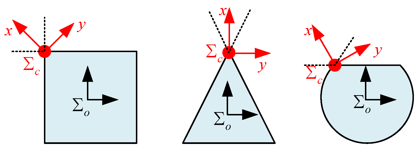
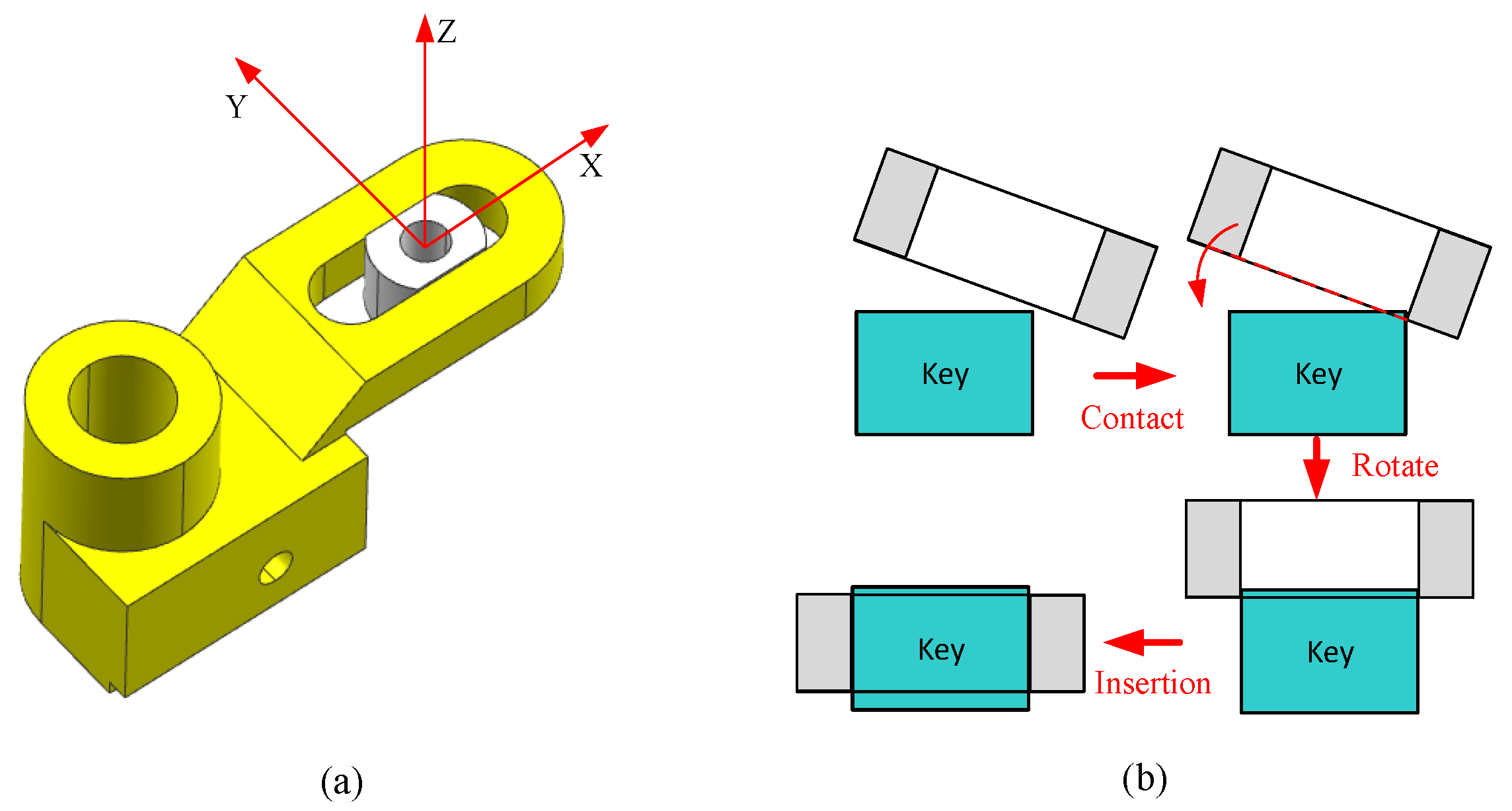
Most studies about errors compensation and hole searching require fully constrained workpieces. According to our investigation, only quite a few papers focus on partial constraint assembly. Some of them are interested in posture detection with a visual sensor. To constrain the workpieces, some of them focus on fixture design, but the complex assistant device is a special design. It has two drawbacks, one is poor universality, and another is the great cost. Therefore, this paper studies the robotic irregular shaped peg-hole assembly problem where the parts are not fixed by building the kinematic model for partial constraint among existing workpieces, analyzing and using the constraint motion features to design a special irregular peg-hole robust assembly control strategy. This method implements the partial constraint peg-hole assembly without any extra accessories. The proposed method can be applied to other irregular peg-hole assemblies where the pegs have the characteristics of discontinuous curvature as shown in the following
Figure 1. The adjacent edges can provide similar characters.
2. Materials and Methods
Assembly is a process that connects several parts together. A typical assembly task relates to at least two workpieces. One is moving while the other workpieces are considered fixed, i.e., fully constrained during the assembly process. Due to the assembly relationship between the workpieces, clearances, or assembly strategies, there may be contact and collision during the assembly process. If the workpieces are not in the fixed state, the workpieces may be driven by the contact force and lead to assembly failure. Therefore, in order to keep the workpieces in a stable state with the existence of external contact force, in the most robotic assembly process, the assistant fixture will be specially designed according to the task parameters.
The fixture can simplify the assembly process. However, a whole assembly process typically involves many workpieces and steps. The special fixture designing process will not only increase cost but also limit the flexibility to adapt to the small batch production. Moreover, a single rigid part can be fixed by multi-point contacts. But in complex tasks, the adjacent assembly steps may couple with each other, and the fixture may be an obstacle for the following steps. In addition, there is inherent relative motion between some workpieces, such as joints, bearing, it’s difficult to design the special fixture for these mechanics.
It is noticed that there are internal constraints between those workpieces. When one part is fixed, the other part is under partial constraint. If the partial constraint can be used, the assembly problem may be able to be accomplished using some special assembly strategies. These constraints can simplify the designing of the assembly process and improve the overall flexibility.
However, there are also many movable joints/mechanisms/parts in an assembly. When performing those assembly tasks in an unstructured environment, the kinematics of those parts have to be considered. These additional freedoms bring a great challenge in the analyzing and control design procedure.
2.1. Key-Slot Assembly
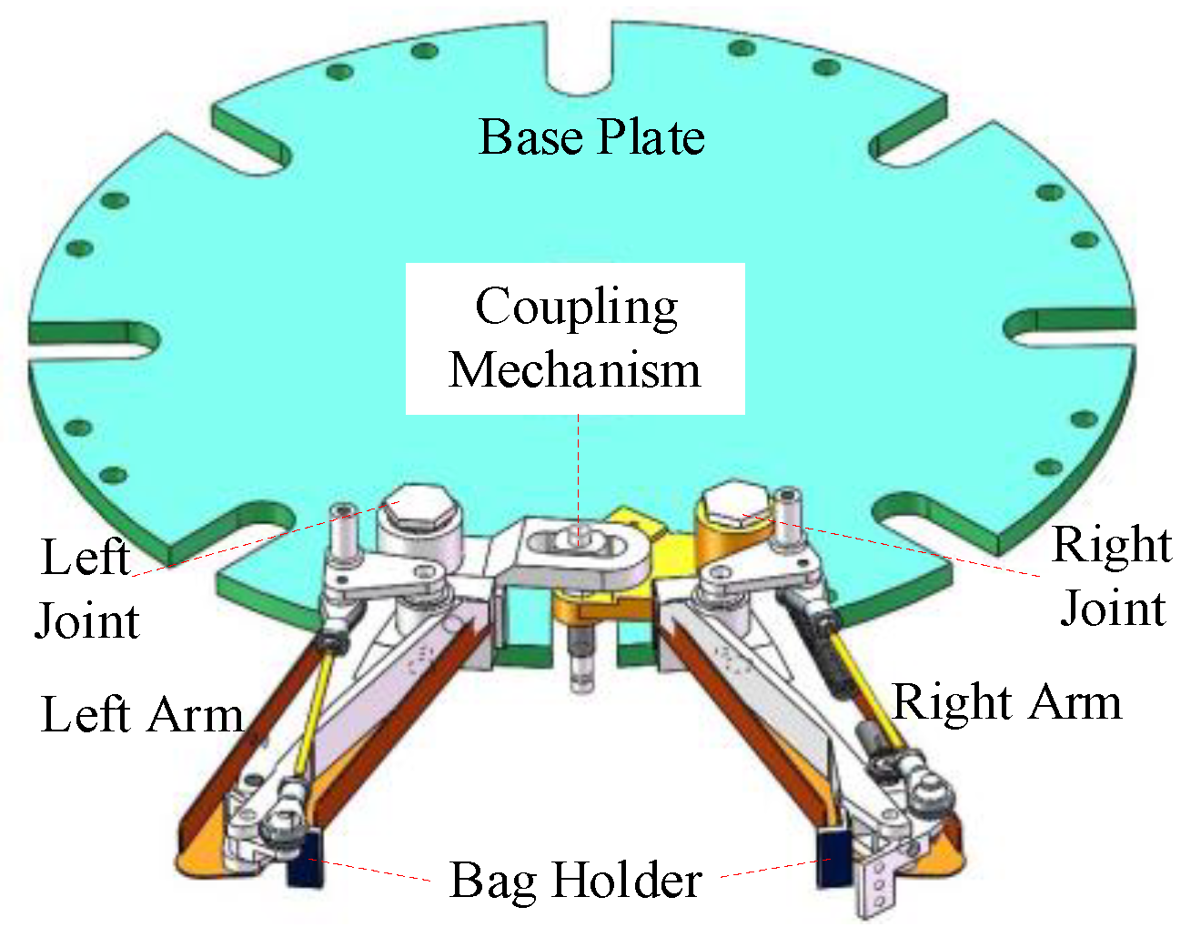
This process comes from a practical project, which aims to design an automatic packaging machine robotic assembly work cell. As shown in
Figure 2. there are two arms used to hold a plastic bag during the packaging process.
The two arms have to rotate to realize the periodic holding and releasing operation. Therefore, the left and right rotational joints have to be installed. Because these joints are coupled with each other, there is a coupling mechanism between them.
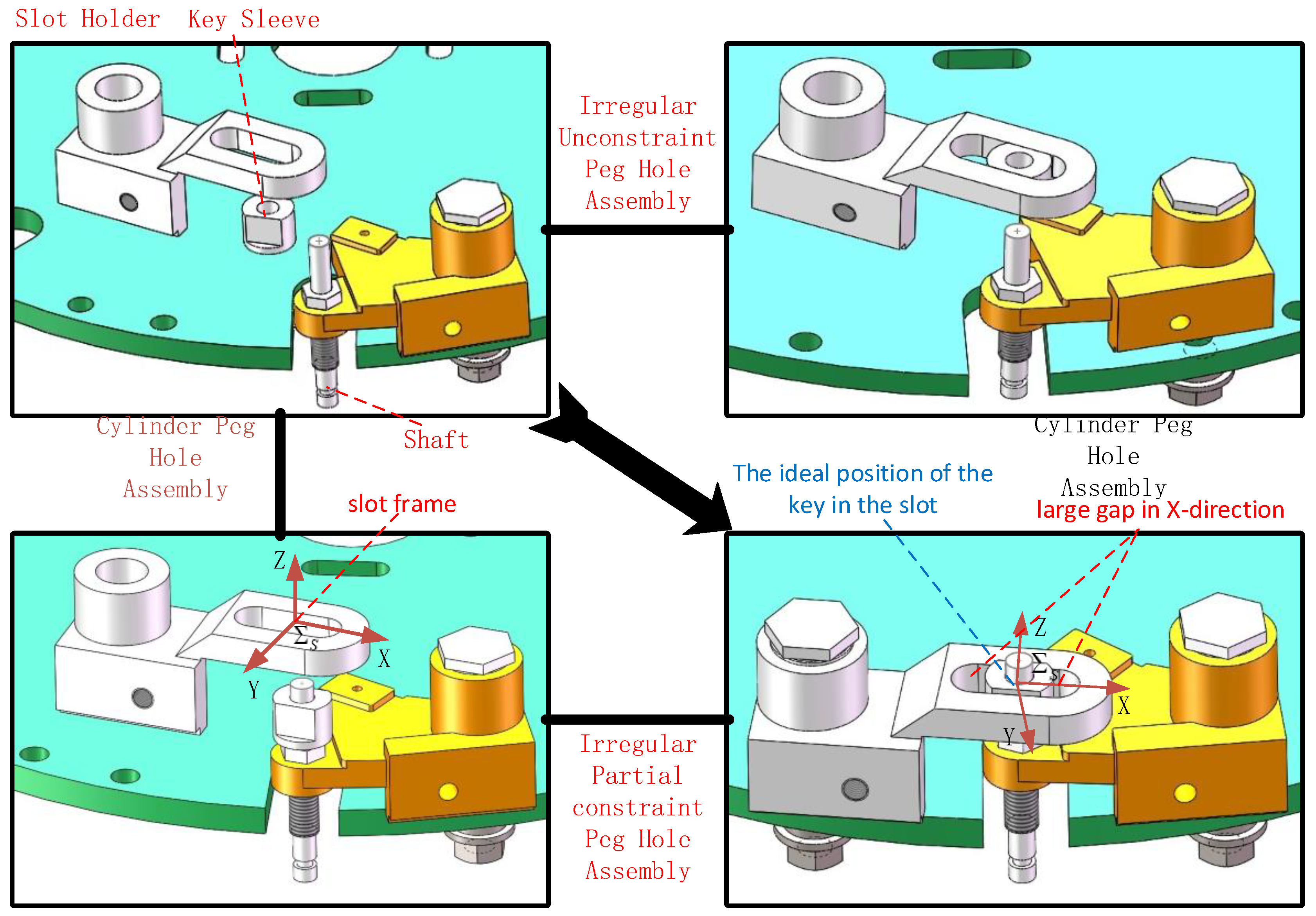
There are three parts involved in the key-slot-shaft assembly process. There is a cylinder hole in the key and the shaft is inserted in this hole, i.e., a typical peg-in-hole assembly problem. The key and slot fit each other and the key can move inside the slot along one direction. To assemble these three parts, two separated sub-assembly operations have to be performed.
As shown in
Figure 3, there are two approaches: key-shaft-first or key-slot-first. The Key-shaft-first approach first installs the key in the shaft by a standard peg-in-hole process, then installs the irregular partially constrained peg hole assembly; The key-slot-first approach first installs the key in the slot then installs the peg by a standard peg-in-hole process. The last step of the
Figure 3 shows the ideal key position in the slot. At this time, the key is located in the middle position of the slot
X-direction, there is a large gap along the
X-direction between the key and the slot. The gap between the key and two sides of the slot are 2.5 mm and a tight gap in the
Y-direction.
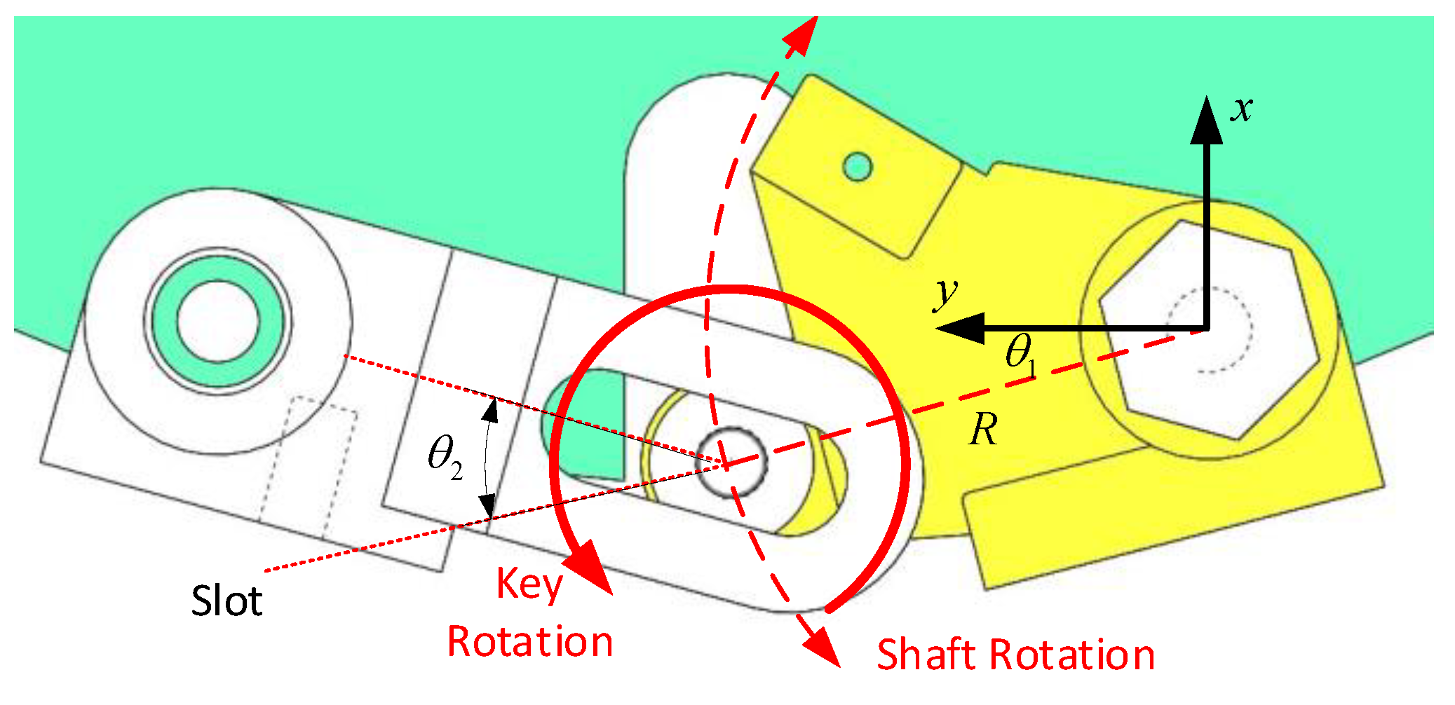
It can be found that besides the common peg-in-hole process, either approach requires a partially constrained assembly process. For the key-shaft-first approach as shown in
Figure 4. because the key-shaft unit rotates around the right joint, the position of the key is not fixed. Furthermore, the key can also rotate around the shaft, therefore, the key has two DOFs during the slot-key assembly process; For the key-slot-first approach, the key is placed on the base plate without any constraints, the external force can drive the key along the surface and rotates horizontally, therefore, the key has three DOFs during the slot-key assembly process.
In this process, only one robot is used to perform the above assembly operation. Another robot could be used to fix the workpiece. However, this requires a specific design of a small gripper to hold the parts while small enough to avoid the potential collision. Therefore, in this paper, an assembly strategy without any fixture is proposed.
The state of the key can be determined by two angles according to the above definition. The goal is to find an appropriate control policy to robustly and efficiently install the slot into the key.
2.2. Modeling and Analysis of Motion Constraint
If the workpiece is fixed, the positional error can be compensated by a searching method or compliant motion. The spiral and linear searching methods are the most commonly used searching strategies. However, in the partially constrained environment, the position of the workpieces may be changed by the searching force if it is not consistent with the constraints. Therefore, if the constraint is known, the force direction could be specially chosen to avoid unwanted motion. In addition, the error may be able to be compensated by the specially designed motion.
Suppose the key-shaft component has an initial posture error as shown in
Figure 4. The angle between joint and shaft is denoted as
. The initial error should be compensated to make the key in a stable and determined position before the slot-key assembly process. Without considering the rotation of the key, the shaft is also not fixed in the XOY plane. As shown in
Figure 3, the shaft rotates around the right joint, therefore, the motion trajectory is a circle with the center as the right joint and the radius as R.
When an external force is applied to the shaft, if the moment of external force is not zero, the shaft will move along the circle. The motion direction is decided by the direction of contact force. The following two situations will be discussed.
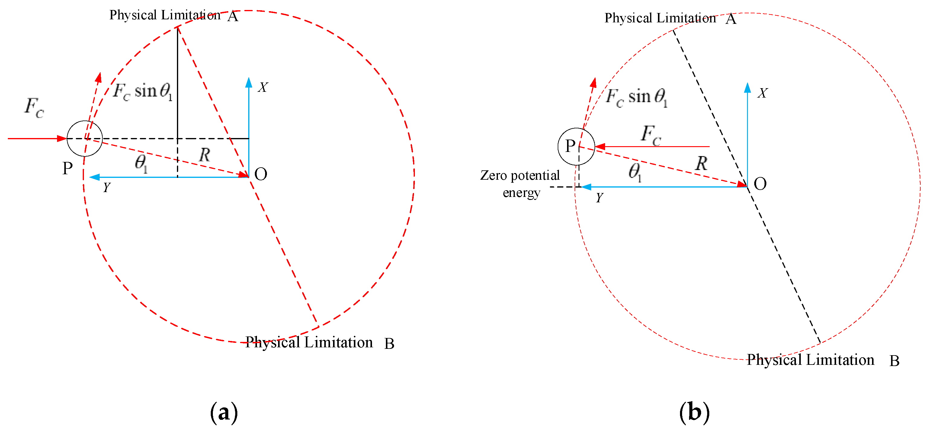
2.2.1. The External Force Points toward the Center
As shown in
Figure 5, regarding O as the center of the right joint, the circle with radius R is the motion trajectory of the shaft. Points A and B are the physical limited positions on the motion trajectory.
The kinematic model of the rotation shaft is:
where,
J1 is the momentum of inertia,
c1 is the frictional coefficient, and
M is the torque caused by the external force.
Assuming P is the position of key-shaft component, according to
Figure 3, this position can be represented as
.
is the external force which is imposed by robot. The force direction points to the center of the joint, as shown in
Figure 4. Suppose the force is along the negative
Y-axis. When
, the external force does not pass through the rotation center. If
the vector of point P is
. The force can be presented as
. Therefore, the resulting torque is:
Equation (2) illustrates that the joint has a clockwise rotation: ; Otherwise, if the joint has an anticlockwise rotation: . Therefore, the position of the shaft will deviate from the point where . In this process, the shaft only has one equilibrium point (). However, the shaft cannot always stay stably in the equilibrium point with this external force due to the initial error and random factors.
2.2.2. The External Force Points Backward from the Joint Center
If turning around the external force direction, as shown in
Figure 4, the vector of external force is
, the torque of external force is:
If the joint will rotate counter clock-wisely: . If the joint will rotate in the clockwise direction, i.e., . The joint will move to a stable point (). In this process, any deviation caused by disturbance will converge to the stable equilibrium point with the external force.
2.2.3. Equilibrium Point for External Force in General Direction
For the shaft under rotation constraint, the equilibrium state will change according to the applied external forces. When the key-shaft component has an initial error, the robot can compensate this error and align the component to a stable equilibrium position by applying a contact force along a special direction. This stable position is unique, determined, and directly related to the external force direction.
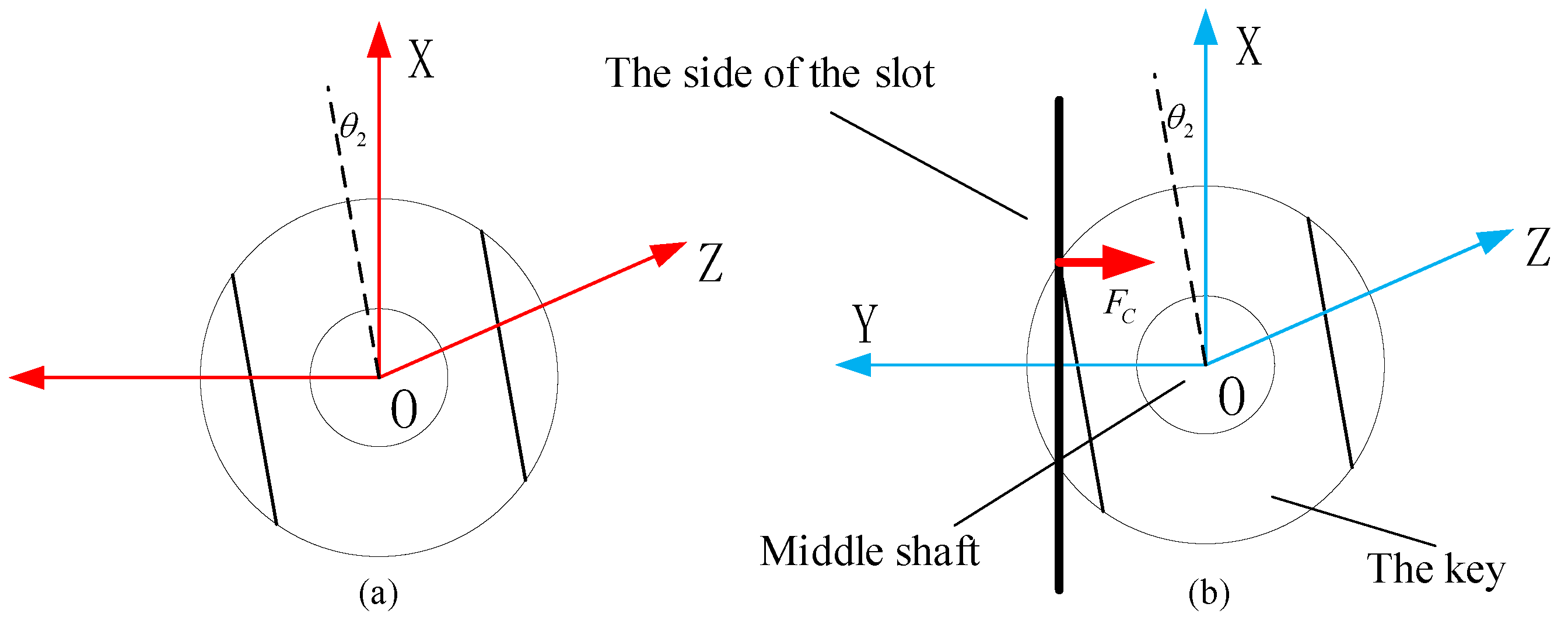
2.3. Behavior Analysis with External Force on Key
In the first step of the assembly process, the key has been installed on the shaft. In the key-shaft component, the key is not fixed. It can rotate around
Z-axis. Because the irregular shaped peg-hole assembly process is sensitive to the angle error, the angle error needs to be corrected firstly. The rotation angle of the key is defined as
Figure 6.
The kinematic model of the key is:
where,
is the momentum of inertia,
c2 is the frictional coefficient, and
M is the external torque.
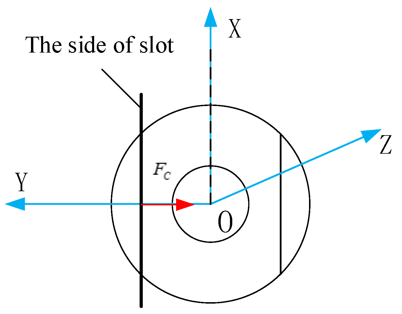
Plane features commonly exist in mechanical parts. Plane to plane or line to plane contact can be used to align two parts. For the key part, there are two side planes which are used to mate with the slot part to form a linear guide mechanism. Suppose another workpiece also has a plane/line feature, the key can be aligned by actively contacting those two parts with the line/plane features.
As shown in
Figure 5, the force is also along
Y-axis. The thick line describes the line/surface feature of the slot part. By applying an external force, the contact type between key and slot parts may be point to plane, line to plane, and plane to plane, due to the rotation error. If the contact form is point to plane or vertical line to plane, the contact force generates a torque on the side of the
X-axis:
where
L is the width of the key. With this torque, the key will rotate around
Z-axis and the angle error will decreases with this rotation until the contact formation changes to the plane-to-plane. The force distributes evenly on the contact surface. At this time, the resultant torque is zero and the key stays in the equilibrium state stably as shown in
Figure 7.
When the contact form is plane-to-plane, the key’s posture has been aligned to the special direction of the contact force.
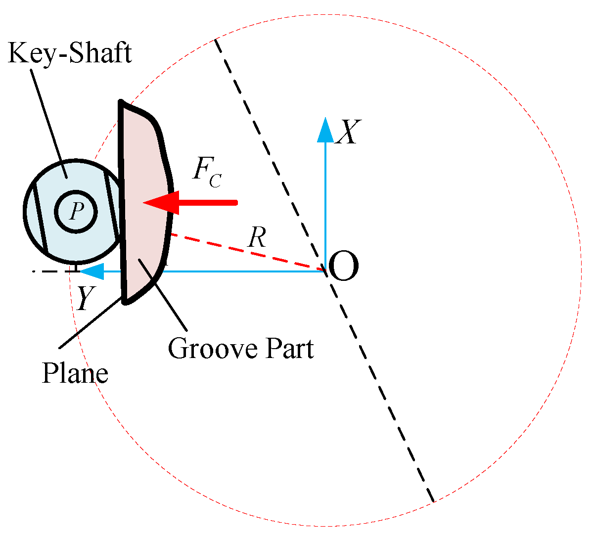
2.4. Simultaneously Regulating the Posture of Key-Shaft Component
According to above analysis, the pose of both parts can be adjusted by applying some contact force and geometric constraint. For rotation joint, applying a contact force which points backward from the center, the shaft can be located at a unique stable position. For the key, the posture can be aligned to an ideal position which normal is parallel to the contact force.
As shown in
Figure 8, the above two alignment processes can be fused together. The desired contact force can be generated simultaneously by applying a specifically chosen force along with a plane feature.
The two alignment operations can be implemented with the same contact force. With a contact force which points backward away from the center of the rotation joint, the key-shaft component can be aligned toward the ideal position together.
The external contact force can also compensate the initial errors, i.e., the key-shaft component will stay in the ideal position stably under this force. Therefore, Even the initial posture of the key-shaft component is not accurate, it can still be stabilized at the ideal position by the proactive contact behavior.
2.5. Behavior Analysis of Irregular Shaped Peg-in-Hole Assembly Process
As shown in
Figure 9, the goal of the key-slot assembly is to insert the key into the slot. Different from the cylinder peg-in-hole task, the robot needs to search the mating position along three different directions when the key-slot component has an initial error. It is a low efficient process. Meanwhile, the spiral and circular searching strategies cannot be used because the key is not fixed. The slot may be moved by the searching force and friction.
Considering the aforementioned part alignment and error correction procedure, a key-slot assembly method is proposed as shown in
Figure 8. The insertion strategies are illustrated in the YOZ plane.
Although the key has been aligned in the previous process, the clearance between the key and slot is too small and direct insertion is hardly possible. Therefore, this paper proposes a two-step searching method as shown in
Figure 8:
(1) Press and contact (pre-insertion)
Because of the position error, it is difficult to directly insert the key into the slot hole. However, when the slot is skew, the corner of the key/peg is relatively easy to be inserted into the hole region.
The bottom of the slot is lower than the upper surface of the key. Keeping this posture and imposing a contact force to the key follows the direction shown in
Figure 8. This force follows along the same direction as used in the part alignment process. In this direction, the key-shaft component can still maintain a unique stable position. Meanwhile, the error in the
X and
Y direction can be compensated with the contact force.
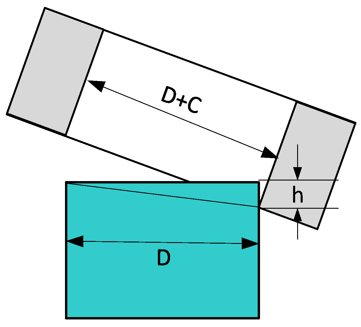
The distance between the bottom surface of the slot and the upper surface of the key plays an important role in the assembly process. As shown in
Figure 10, if the depth h is too shallow, the contact is sensitive to uncertainty and stable contact may not be able to maintain. If the depth h is too deep, the slot may jam during the following rotation and insertion process because the gap between the hole and peg is very narrow. Therefore, this is the significant parameter, which affects the success rate of the insertion process. As shown in
Figure 10. The depth of pre-insertion and the assembly clearance decide whether the slot can be installed onto the key. Because of the position error, it is difficult to directly insert the key into the slot hole. However, when the slot is skew, the corner of the key/peg is relatively easy to be inserted into the hole region.
The bottom of the slot is lower than the upper surface of the key. Keeping this posture and imposing a contact force to the key follows the direction shown in
Figure 9b. This force follows along the same direction as used in the part alignment process. In this direction, the key-shaft component can still maintain a unique stable position. Meanwhile, the error in the
X and
Y direction can be compensated with the contact force.
The distance between the bottom surface of the slot and the upper surface of the key plays an important role in the assembly process. As shown in
Figure 10, if the depth
h is too shallow, the contact is sensitive to uncertainty and stable contact may not be able to maintain. If the depth h is too deep, the slot may jam during the following rotation and insertion process because the gap between the hole and peg is very narrow. Therefore, this is the significant parameter, which affects the success rate of the insertion process. As shown in
Figure 9. The depth of pre-insertion and the assembly clearance decide whether the slot can be installed onto the key.
As
Figure 10 illustrated,
h is the depth of pre-insertion,
D denotes the width of the key/peg,
C is the clearance. The success condition of insertion is:
The depth of pre-insertion is determined by the size of workpieces and their clearance.
(2) Hole searching by rotating around the X-axis
When the slot and key contact with each other stably, the contact form is line to surface contact. This is a stable contact because the contact force is still along the positive direction of the
Y-axis. For the slot, two degrees of freedom are constrained. The velocity constraint equation is:
As this constraint equation illustrated, the slot cannot translate along the Y-axis and cannot rotate around Z-axis. Since clearance along X-axis is relatively large, at this time, only the rotation around X-axis is relative to the insertion process.
As shown in
Figure 8, since the slot is already skew around
X-axis, the searching action can be completed by rotating around the
X-axis counter clock-wisely. If the depth h satisfies the condition (6), it is able to insert the slot into the peg with the single DOF search action. Once the slot is on the peg, the reaction force/torque is generated that indicates the accomplishment of the searching process.
(3) Final insertion and settling down
When the pre-insertion process is finished, the key/peg already is inserted into the slot/hole. Because of the rotation force and the pushing force, the slot jams. In the final stage, a normal peg-in-hole insertion strategy is used to compliantly insert the key/peg into the slot/hole. Because of geometric constraints between the key and the slot, the slot can only move linearly along the X and Z axis. This is similar to the peg-in-hole process and it can be implemented by a hybrid position/force control policy.
Note that in the whole insertion process, the contact force is always applied in the Y direction. It will ensure that even if there are other contact forces on the workpieces, the position of the key-shaft component will not change during the assembly process.
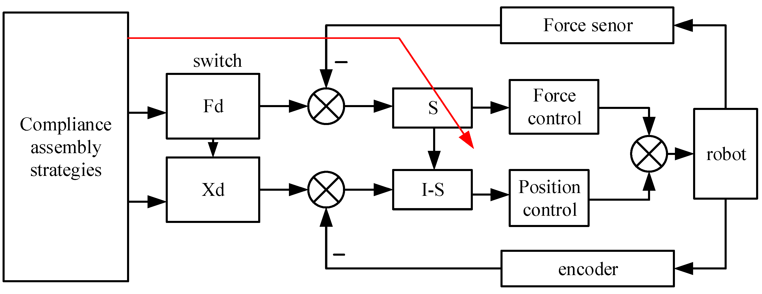
3. Control Strategies of Robotic Assembly Task
From the above analysis, it can be seen that in the process of alignment, pre-insertion, rotation search and vertical insertion, there are different geometric constraints and control requirements in different directions in the task space. The controller needs to regulate the force in some direction and regulate the position in other directions. Therefore, it can be implemented as hybrid force/position control.
Figure 11 shows the block diagram of the control system.
The above three stages correspond to different selection matrix and reference motions, respectively:
- (1)
Press and contact (pre-insertion) stage:
- (2)
Hole searching stage:
- (3)
Final insertion and settling down stage:
According to the contact force, torque, displacement, and other information, the above three stages is switched and coordinated to complete the task of the irregular shaped and partially constrained peg-hole assembly process.
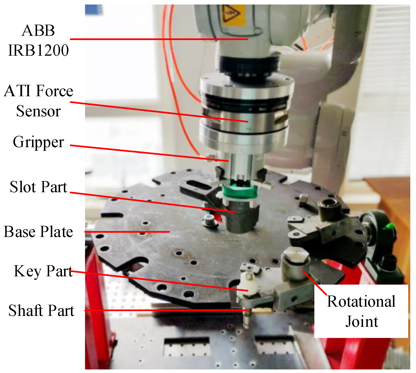
4. Experiment
In order to verify the effectiveness of the proposed method, it is implemented in the platform as shown in
Figure 12. An IRB1200 robot (ABB, Shanghai, China) is deployed to perform the partially constrained irregular shaped peg-hole assembly task as shown in
Figure 12.
The robot is equipped with a pneumatic gripper to grab the work pieces. An ATI 6DOF force/torque sensor is installed at the end effector to measure the contact force. The robot is controlled by the IRC5 controller. There is built-in force control functionality which can provide hybrid force/position control capability.
For the used parts, the width of the slot is 14.06 mm while the width of the key part is D = 13.96 mm. The clearance C is 100 μm. There are no general restrictions on dimensions of the key part and the slot part. However, in order to ensure the success of the hole searching, there are constraints as described in (6) between the size of the two workpieces and the pre-insertion depth.
4.1. Simultaneously Regulating the Posture of Key-Shaft Component
Because the parts are not fully constrained, the random contact forces or uncertainties in griping postures may lead to different parts locations and poses. It is supposed the slot has been grabbed by the robot gripper and the key has been installed on the shaft. The goal is to install the slot on the key-shaft component.
As previously discussed, the key-shaft assemble can be aligned by pushing it from some particular direction with a plane surface. It is noticed that there is a plane surface in the slot part. In order to make the programming process simpler, the pushing direction is chosen as the
Y-axis of the robot base coordinate frame. The control algorithm follows (8) and the contact force is set as 5 N. With this controller, the component can be aligned to an ideal position and posture. Snapshots of the aligning process are shown in
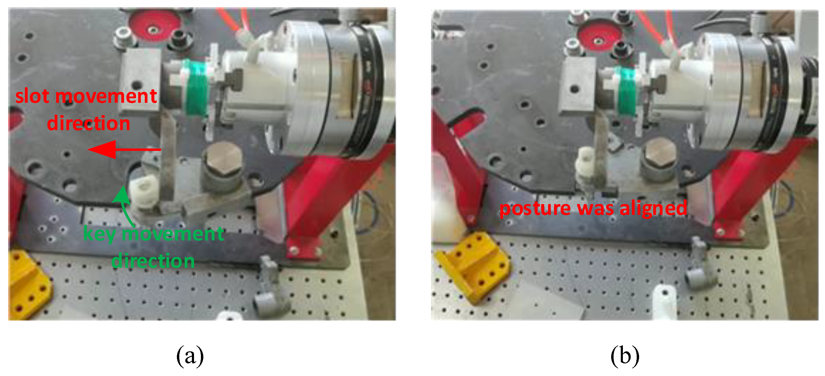
Figure 13.
Figure 13a shows the initial configuration, where the key-shaft component has both position and posture errors. The bottom surface of the slot part is a plane. The robot turns the slot part 90 degrees to let the plane face toward the side plane of the white key part. Then a hybrid force/position control policy is applied to use the side plane to impose a contact force along
Y-direction according to the process discussed in
Section 2.2 and
Section 2.3. After contact, the key-shaft assembly starts to rotate toward a stable position and pose. the red arrow shows the slot motion direction and the green arrow shows the key-shaft component motion direction.
Figure 13b shows the final stable state for those parts, where it is seen that the key, shaft, and slot plane are well aligned. In this process, the initial error can be compensated and the components are aligned to the ideal position.
4.2. Hole Searching and Insertion
After the alignment process, the key and shaft parts are steered at a fixed position and posture. Therefore, the slot-key assembly can be performed afterward. The following steps are required to complete the process:
- (1)
Change the slot part posture to vertical posture and let the hole face downward;
- (2)
Drive the slot part to a skew state and make sure the bottom edge is below the top surface of the key part (According to physical parameters and (6), h = 1 mm);
- (3)
Move the slot part toward the key until contact and keep contact during the searching process;
- (4)
Rotate the slot around the contact edge in a counterclockwise direction using the force control policy (10) until the slot is jam with the key;
- (5)
Compliantly insert the slot into the key using force control policy (11).
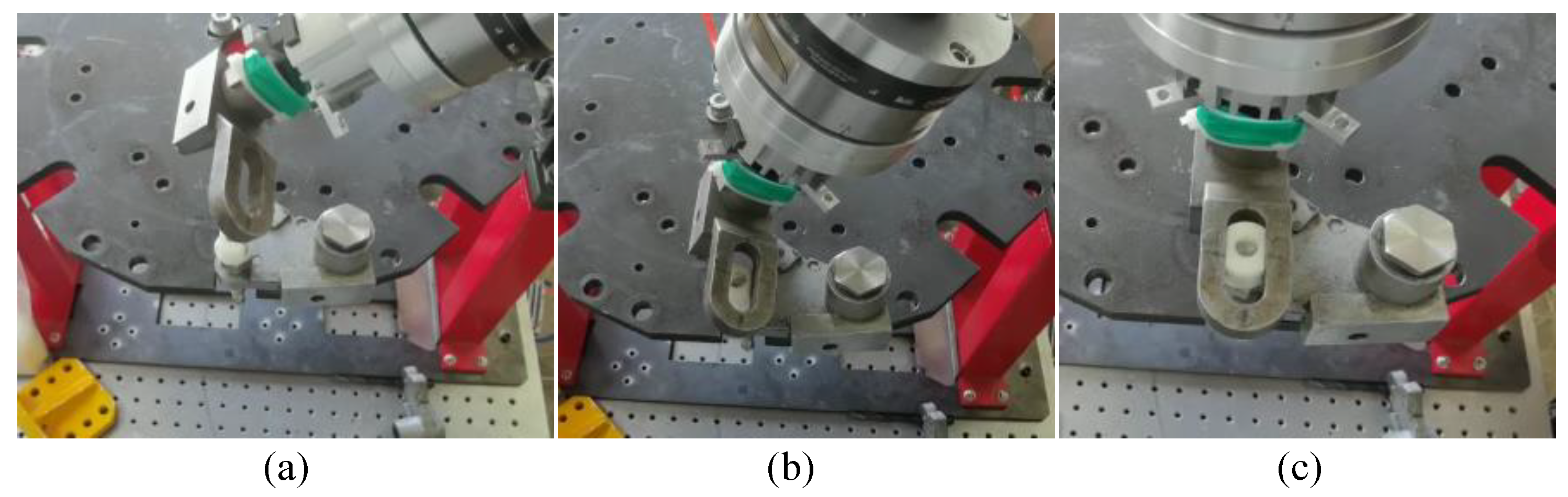
Figure 14 shows the snapshots during the hole searching and insertion process. In
Figure 14a, the part was reoriented to a pre-search skew posture; In
Figure 14b, the slot is in contact with the key and ready to perform a circular searching action; In
Figure 14c, the key has been critically inserted into the slot hole and it is ready to perform the final insertion.
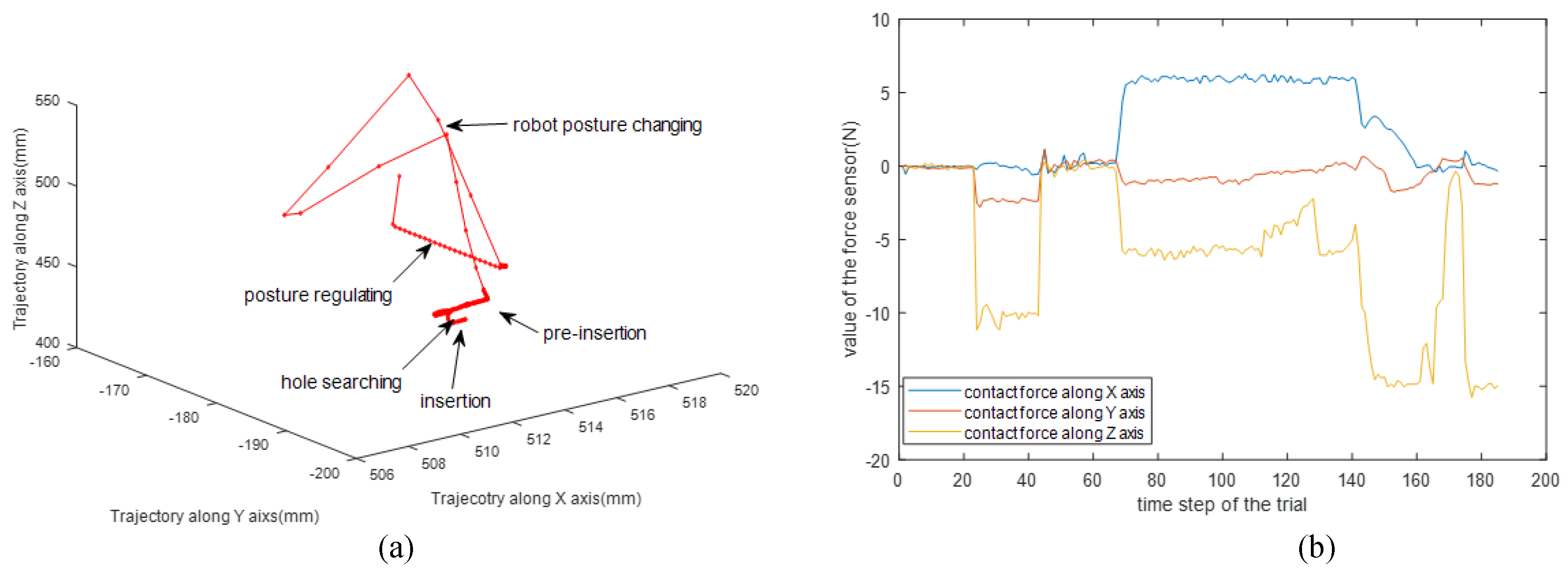
When all above assembly operations have been completed, the experimental data shows in
Figure 15. The trajectory of the robot end-effector was shown in
Figure 15a. As the figure shown that four stages of the assembly were presented explicitly. The three directions force were shown in
Figure 15b. The force change along the
X and
Z axes denotew the different assembly stages.
In the posture regulating and pre-insertion process, the control system switches the force control mode. As Equations (8) and (9) denote, the direction of force controlling is along the Y-axis of the workpiece’s frame. In the hole searching stage, the two directions of impedance control are along Y-axis and around X-axis.
The robot posture is illustrated in
Figure 13 and
Figure 14. Posture regulation is a
Z direction force control process, and the hole searching is an impedance control process along the
X and
Z directions, respectively.
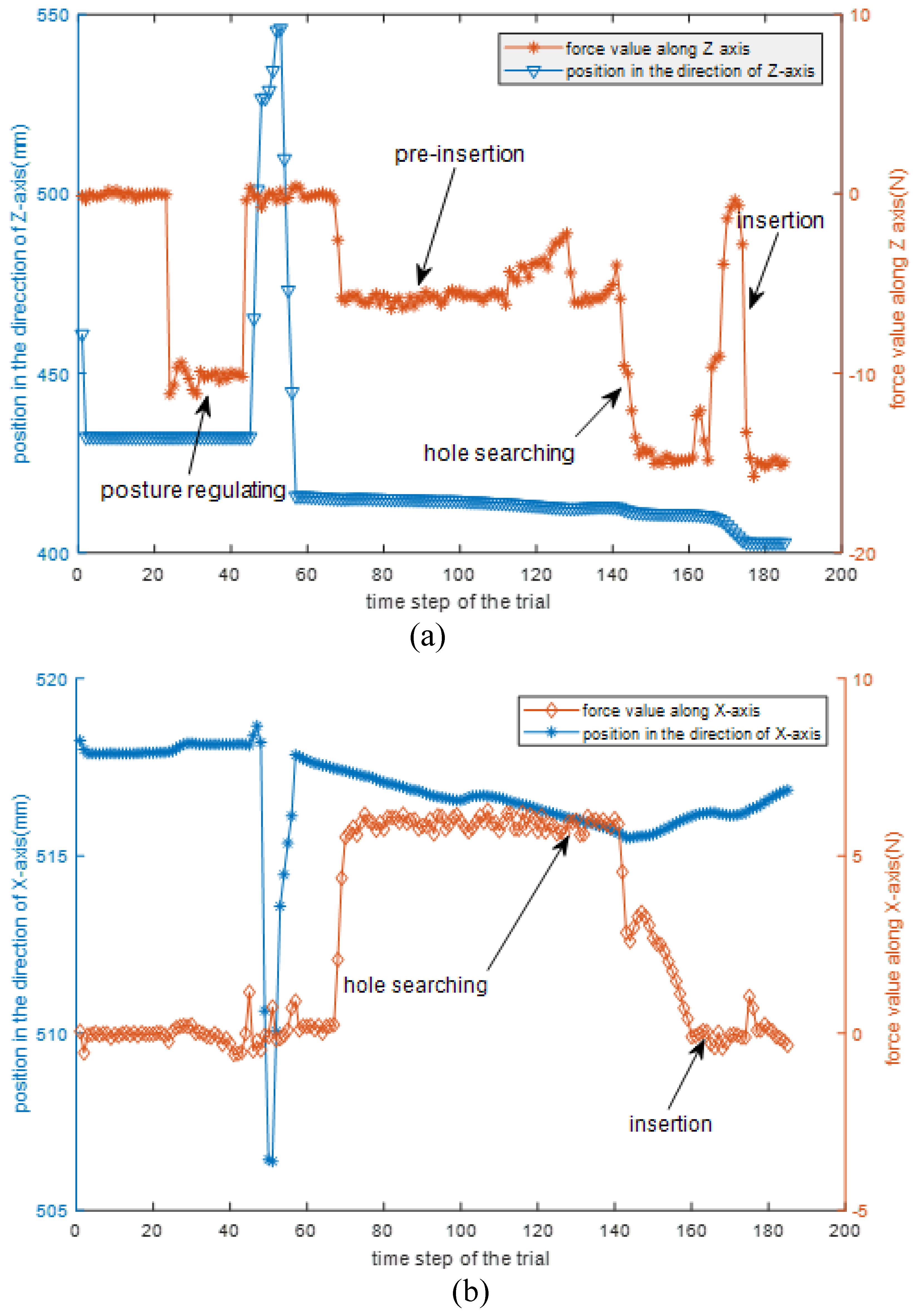
Figure 16a shows the
Z trajectories and force value along the
Z-axis. It explicitly illustrates the changing of the force and the trajectories according to the assembly stage. The
X-axis trajectories and contact force is shown in
Figure 16b. It mainly describes that the force changes in the pre-insertion and searching stage, respectively.
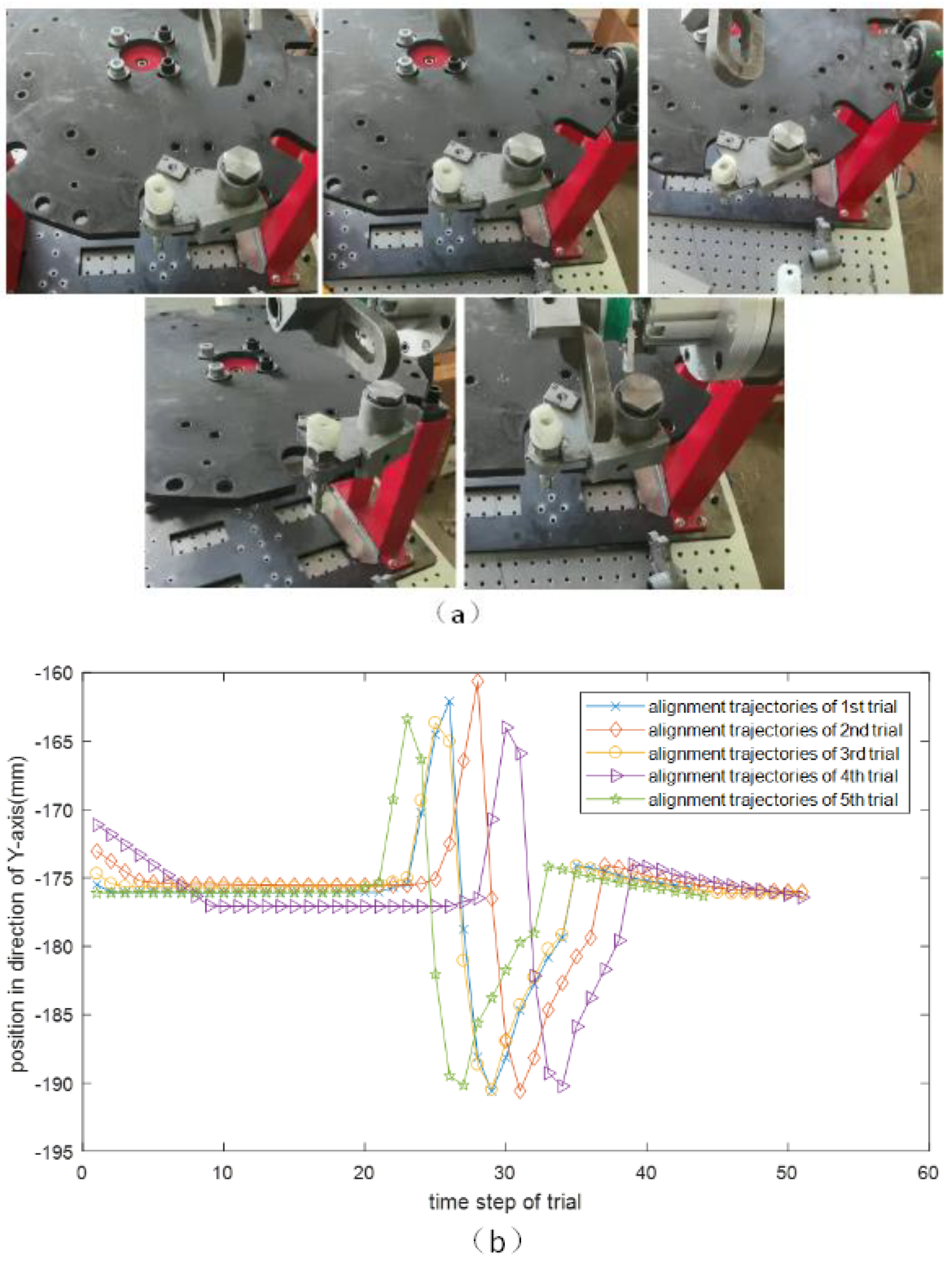
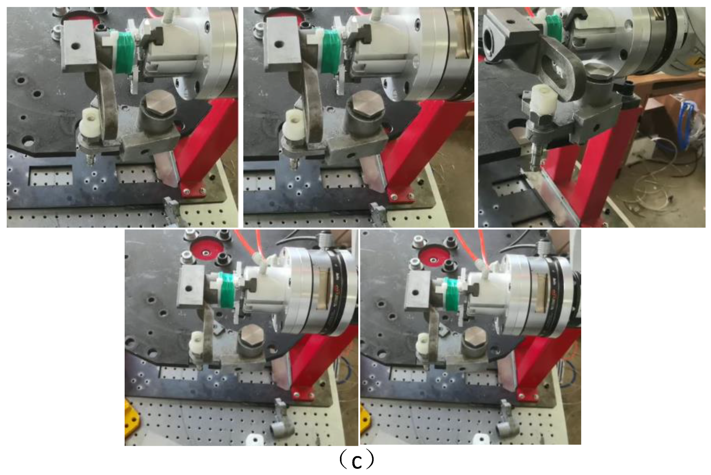
To validate the repeatability and reliability of the proposed method, the above assembly operations are repeated five times. The simultaneous regulation stage is the most important stage in this experiment. The hole searching and insertion stage will succeed only if the simultaneously regulation is successful. The initial position and posture of the key-shaft component in snapshots shown in
Figure 17a. The robot using force control along
Y-direction in the simultaneously regulates the posture of key-shaft component.
Figure 17a illustrates that the key-shaft component have a different initial position and posture. When the robot finishes the simultaneously regulation stage, the position and the posture of the key-shaft component has been aligned to the same position.
Figure 17b shows the initial and final position of the robot end-effector in the regulation stage and the aligned posture from five experiments is shown in
Figure 17c.
Figure 17 shows that the initial position and posture errors of the key-shaft component will be corrected after the simultaneously regulation stage. The key-shaft component is aligned to a stable posture. The proposed method is tested in different situations and shows very good repeatability.


