Article

Development Workflow for Manifolds and Fluid Components Based on Laser Powder Bed Fusion

Department of Processing Technologies, Fraunhofer Institute for Casting, Composite and Processing Technology IGCV, 86159 Augsburg, Germany
*
Author to whom correspondence should be addressed.
Appl. Sci. 2021, 11(16), 7335; https://doi.org/10.3390/app11167335
Submission received: 30 June 2021 / Revised: 1 August 2021 / Accepted: 5 August 2021 / Published: 9 August 2021
(This article belongs to the Special Issue Design for Additive Manufacturing: Methods and Tools)

Abstract

:

Featured Application

This article proposes a universal development methodology for hydraulic manifolds and fluid components manufactured by laser powder bed fusion. The proposed process leads systematically to a part with increased performance characteristics, economic efficiency, and reliable manufacturability.

Abstract

Through its unique characteristics, additive manufacturing yields great potential for designing fluid components with increased performance characteristics. These potentials in advanced design, functional structure, and manufacturing are not easily realized. Therefore, the present study proposes a holistic development methodology for fluid components with a specific focus on hydraulic manifolds. The methodology aims to lead the designer from the specification of the task, through a step-by-step embodied design, to a technical and economic evaluation of the optimized, first-time manufactured part. A case study applies the proposed methodology to a part of a rail-vehicle braking application. Through its application, a significant reduction in weight, size, as well as significant contributions to the company’s AM strategy can be assigned to the part. At the same time, increased direct manufacturing costs are identified. Based on the increased performance characteristics of the resulting design and the holistic foundation of the subsequent economic decisions, a satisfying efficiency can be allocated to the proposed methodology.

1. Introduction

Additive manufacturing (AM) describes all manufacturing processes in which the part is fabricated by adding volume elements layer by layer to produce the desired geometry. The added elements are directly derived from the 3D data [1]. AM technologies have been advancing steadily through the years. Especially the sector of metal AM matured from niche applications to mainstream manufacturing and is being accepted as a valuable production process for demanding engineering tasks. For metal applications, laser powder bed fusion (LPBF) is the most widespread manufacturing principle [2]. When designing parts specifically for AM, these technologies yield unique characteristics in advanced geometric freedom, part consolidation, and product customization in comparison to other manufacturing processes. Through the given geometric freedom, new potentials in the performance and economic efficiency of the product are enabled, which can be realized through advanced design. If such a design can consolidate multiple parts of an assembly, additional improvements in size, weight, and assembly effort are achievable [3]. In the LPBF manufacturing process, differences in the individual geometry of parts manufactured in one build job have minor influence on the economics of the build job compared to conventional manufacturing methods. This leads to an economic feasibility of a lot size of one and makes the technology therefore practical for highly customized products [4]. However, these potentials are not easy to identify nor to realize. It requires the designer to have a fundamental understanding of the technology and to re-think the system-level design of the product [5]. Existing, universal product development methodologies are applicable for AM parts, but can hardly exploit the given potentials efficiently due to the design complexity and multitude of possible solutions [6]. Nonetheless, as a development of a completely new design process is neither efficient nor possible, development guidelines for AM products should be based on established methodologies and further recognize the specific potentials and limitations of the technology. As the VDI 2221 [7,8] guideline is widely accepted as a core standard for the development of technical products and was previously suggested for an AM specific methodology [9]. Kumke bases the general structure of his comprehensive method for the development of AM parts onto it [5].
As for any other manufacturing method, design guidelines have to be followed for a qualitative and economic fabrication of the designed part. The established methods of design for manufacturing (DfM) aim for design solutions with minimum manufacturing costs for a given manufacturing technology. Even though such guidelines for favorable manufacturing are still an elementary part of a design for additive manufacturing (DfAM), these methods shall further support the exploration of AM-enabled potentials and possibilities. Laverne et al. propose to differentiate opportunistic DfAM, restrictive DfAM, and dual DfAM [10]. Opportunistic DfAM methods shall enable the designer to explore innovative solutions enabled by the possible geometric complexity of AM products. The solution space of such methods is not narrowed by the limitations of the AM technology as in the definition of conventional DfM. These limitations are covered in the class of restrictive DfAM methods. In these, design rules are defined, that guide the designer to create a part with sufficient manufacturing quality. The majority of such design rules are developed in university research through test series [11,12,13,14]. These restrictions can be quantified as for minimum radii or wall thicknesses, as well as general guidelines for a sufficient manufacturing result [14]. They are more and more transferred into official design guidelines [15] and textbooks [4]. Finally, methods utilizing a combination of both, restrictive and opportunistic DfAM, are considered to be the most efficient for a holistic product design manufactured by AM technologies. With these, innovative concepts are designed for a qualitative manufacturing outcome [5]. Therefore, for each classification, different tools as depicted in Figure 1 are suggested.
Manifold bodies in pressure-loaded applications are traditionally manufactured from a solid material block, creating the hydraulic schematic by intersecting, gun-drilled holes. For manufacturing efficiency, these channels are usually manufactured with a 90° orientation towards the outside surface of the semi-finished block. All unused openings are closed by sealing stoppers in a subsequent assembly process. As a result, complex hydraulic schematics require a larger manifold due to the inflexible channel design, a greater number of drilled holes, and therefore a greater number of sealing points. Furthermore, the perpendicular, sharp corners in the fluid flow decrease the flow efficiency of the hydraulic medium. Through the AM-enabled geometric complexity, manifold bodies hold great potential for increased product performance through advanced design [4].
A comprehensive approach to the development of hydraulic manifolds fabricated by LPBF systems is the work of Kausch [16]. After extensive research on various topics concerning the development of AM manifolds, the generated knowledge is transferred onto two different manifolds, which are manufactured by LPBF. The evaluation of the part proves a great potential for weight reduction of high-pressure manifolds and suggests similar production costs to the conventional counterpart with further process and productivity improvements of the technology. The research of Diegel et al. [17] follows an existing AM manifold design and focuses on the further optimization of the manufacturability. This includes primarily the reduction in support structure to minimize manufacturing and post-processing time. Schmelzle et al. [18] present a specific flowchart for the re-design of hydraulic manifolds. The study places special focus on the channel cross-section geometry as well as a detailed description of manufacturing, inspection, and testing of the resulting manifold. Zhang et al. [19] approach a manifold re-design with the motivation of an optimized fluid flow and adapt each phase of the development process accordingly. As in the previous studies, a significant optimization in weight, size, and fluid flow efficiency is achieved. Cooper et al. [20] examine the pressure, flow, porosity, surface and micro-hardness characteristics of a titanium pipe manufactured by LPBF. The research offers detailed findings on the pressure resistance of thin-walled pipes, their internal surface roughness, their as-built geometric accuracy as well as the characterization of the porosity of the material. Table 1 depicts an overview of manifold-specific information in reviewed studies.
The review of conducted research on hydraulic manifolds shows that the re-design process systematic is an important topic for most studies. The models and flowcharts presented for a re-design are often rudimentary for the task of developing an additively manufactured manifold with increased performance while ensuring qualitative and economic manufacturability. Most of the reviewed studies only utilize restrictive DfAM methods for their design. The very detailed approach of Kumke [5] on the complete design process for AM, applying restrictive and opportunistic DfAM, has not been applied for a hydraulic manifold application. Furthermore, the number of hydraulic components and the resulting complexity of the reviewed manifolds remain in a range of 3 to 10 installation spaces.
Based on the state of the art in the development of AM manifolds, a research deficit on the systematic development of manifolds with advanced hydraulic complexity and additional functional requirements is identified. Product improvements through the application of opportunistic DfAM are often left unused. Consequently, the present article aims to propose a universal development and design methodology that leads systematically to a manifold with improved product performance while being optimally designed for qualitative and economic manufacturing by LPBF. After the methodology is presented, its applicability and efficiency are assessed with a case study on a safety-critical manifold of the rail industry.
For the methodology development, the following requirements are defined:
  • The universal applicability of the process must be given. The design methodology shall serve hydraulic applications independently of the specific product.
  • The process shall facilitate opportunistic DfAM potentials by introducing specific methods and tools when necessary.
  • Restrictive DfAM methods and tools are to be introduced to the process when necessary.
  • The process shall lead to an AM geometry that embodies the optimum quality and profitability of the build job.
  • The process shall systematically lead to a manifold with increased performance characteristics such as improved weight, size, or flow efficiency.
  • The process shall allow an iterative shift between the different phases to utilize an experience gain of the user for upstream phases.

2. Methodology Development

As previously identified, Kumke [5] offers a comprehensive process model for the universal development of AM parts. To guide the designer to a design that respects technological as well as economic aspects, this process constitutes the general structure of the proposed methodology. This structure is, however, supplemented with manifold-specific design phases and tasks. Additionally, suitable tools for the specific tasks are proposed. In that way, the methodology facilitates a complete exploration of the potentials enabled through advanced design while acknowledging the economic efficiency and reliable manufacturability of the resulting part.
As depicted in Figure 2, the proposed development methodology starts with the planning and conceptual phase. These phases, including their individual steps, are transferred analogously from the VDI 2221 [7]. Based on the high significance of a detailed description of requirements, an independent list of requirements for the part is to be created in the first task. This list should describe all boundary conditions concerning the part, available AM technologies, material availability, and loads. This is a mandatory process step, which is executed for re-design tasks as well as new development tasks. Even though the requirements shall be formulated detached from the manufacturing technology used, AM-specific potentials and resulting requirements, for example, lightweight design, can already be addressed [5]. In the second task, the functional structure of the part is to be arranged hierarchically into main and sub-functions (cf. Figure 2) [21].
The exploration of design freedom in new- as well as re-designs benefits significantly from function-based thinking, being detached from conventional manufacturing restrictions. In doing so, all surfaces which serve a specific engineering function shall be identified, and their individual boundary conditions, for example, freedom of position, is specified. This facilitates a subsequent, flux of force-oriented design. Based on this analysis, different conceptual solutions for the identified, functional structure are to be developed in the third task. To assist the designer in exploring unconventional solutions, tools like “AM-potential checklists”, “the analysis of existing studies” or “cross-departmental brainstorming” can be utilized during this task. It is important to conduct such an extensive conceptual phase for re-designs as well. Existing solutions may include conventional thinking barriers, whereas the presented steps and tools create a large solution space for innovative concepts [5].
In the following task four, the concept assessment, the acquired concepts are evaluated by “pairwise comparison” and “value benefit analysis”, which are specified/recommended in VDI guideline [7]. The assessment criteria for the value benefit analysis need to be adapted to consider the new AM aspects [5]. The following criteria are proposed for the assessment of manifold concepts:
  • Potential for size reduction
  • Potential for weight reduction
  • Potential for improved hydraulic efficiency
  • Technical feasibility/ development risk
  • Degree of innovation
  • AM material efficiency
  • Profitability of the build job
Based on the quantitative assessment, one concept is selected for the embodied design phase. In this phase, potentials for improved product performance can be realized through advanced design. The chosen concept is introduced to the decision knot, in which tasks five to seven are executed iteratively. First, the parts main elements are designed and positioned according to the specified boundary conditions [
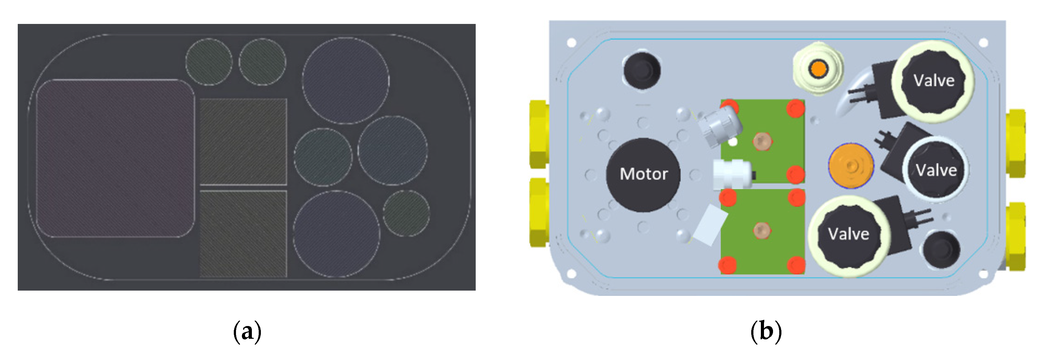
5]. For manifold bodies, these are primarily installation spaces, hydraulic connectors, fixation points for the motor, and pump. If the position of an installation space for a hydraulic component was specified as variable in the analysis of functional surfaces, its position in the AM design shall regard the following three aspects. Its position within the hydraulic logic, the assembly and accessibility with the required tools, and finally an efficient nesting of the valves, sensors, and motor. There are several software solutions [22] available, which create two-dimensional nesting solutions for a set of defined geometries. For a re-design, it is important to question existing component positions, as conventional manufacturing constraints may have lost relevance through AM.
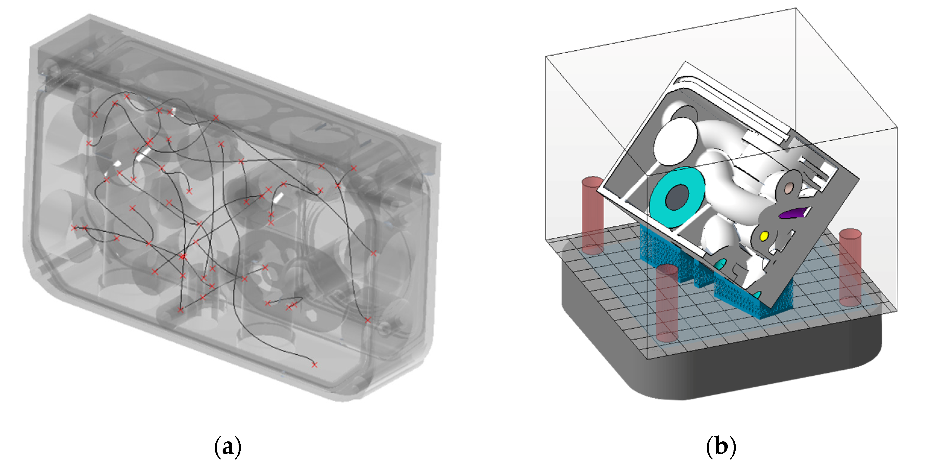
Once these elements are positioned, the orientation of the part within the build space of the LPBF system is to be chosen. This decision has a fundamental influence on the design of subsequent geometries, the manufacturing quality of the part, the necessary amount of support material, and finally, the economic efficiency of the build job. After the technical feasibility of the selected orientation is proven by a manufacturing simulation, a preliminary economic assessment is conducted in task seven. The outcome of this decision sequence is often a compromise of minimum manufacturing time, best manufacturing quality, mechanical properties, necessary support material, and manufacturing costs [17]. It shall therefore be repeated iteratively until the best compromise for the given boundary conditions is found. Additionally, if no such compromise can be found, the decision knot at this early stage of the development process prevents the usage of further resources on unpromising concepts and questions the suitability of AM for the specific project [5].
As the main elements are usually standardized installation spaces and threads, the DfAM potential lies mainly in the design of the hydraulic interconnection of the installation spaces. The channel diameter is to be selected according to the present fluid flow of the application [23]. Circular channels with a diameter greater than 7 mm require internal support structure [16,18,24]. As the complex channel design makes these structures inaccessible, they must be avoided. Multiple studies provide restrictive design guidelines for non-circular channel cross-sections [16,18,25]. Additionally, an appropriate wall thickness must be selected, which resists high, cyclic pressure load over the complete lifetime as specified in the requirements list [16,26,27,28]. The design complexity enables channels that can be designed conformal to existing walls and installation spaces, sharing a single wall, and saving thereby AM-material and manufacturing process time. Through this design flexibility, the size of a manifold is not limited by the channel layout anymore.
As most functional surfaces require a high surface quality and geometric precision, they must be post-processed with subtractive processes [18]. In task nine, the necessary machining offset, registration features, and clamping positions are added to the geometry to enable precise machining. Again, these features shall be designed according to restrictive design guidelines presented in the literature [25,29]. Further, referencing strategies for subtractive operations on defined registration points shall be established at this point.
All geometric elements designed in tasks five to nine serve a specific function. Even though these elements are designed under consideration of restrictive DfAM guidelines and the chosen orientation, the geometric complexity requires compromises in the usage of support for certain elements. However, it is a major intention of DfAM to minimize the usage of supports, as they require extensive manual labor for their removal [25]. Consequently, most of the necessary support structures shall be replaced by design elements, for example, thin walls, which are not removed and serve as additional stiffening elements. Support-critical areas are identified by build-preparation software [30] and then replaced by geometric elements in the design software iteratively.
As the final part of the embodied design phase, task eleven takes into account the post-processing of the part. For manifold bodies, the powder removal from the complex channels is of high importance. Therefore, the entrance and exit of every channel must be designed with an opening in the unfinished manifold. Further, considerations on the deburring of the machined installation spaces and the final cleaning of all channels are taken into account. These processes must remove all chips, coolant-, oil-, or powder residuals from the manifold in- and outside.
The proposed sequence of eleven tasks leads to the unfinished AM geometry, which is manufactured on the available LPBF system. Due to the definition of all boundary conditions at the beginning of the development, the resulting design shall be suitable for the given AM system and its limitations. To verify the decisions taken in the previous steps without the financial and time-consuming risk of a complete, fully utilized build job, this study proposes to manufacture a section of the complete manifold, which contains critical features, under similar fabrication circumstances. In a second manufacturing step of the pre-study, the efficiency of the projected machining strategy is assessed, and necessary alterations to upstream tasks can be implemented. If the pre-study does not indicate issues in the additive manufacturing and subtractive finishing, the complete, first build is to be manufactured and finished according to the specifications in the manufacturing phase.
To enable comprehensive product development, it is the final task of the proposed methodology, to assess the developed manifold by technological as well as economic aspects. For the technological assessment, firstly, all resulting product characteristics such as weight, size, fluid flow, or mechanical resistance are to be identified and matched with the requirements list. Secondly, all noticeable problems identified during the build job, or by visual inspection of the part and their cause are to be described. Finally, as the internal shape of the manifold is of high importance for its functionality but may be inaccessible by endoscopes due to its complex shape, industrial computer tomographic (CT) scanning is suggested to inspect the manifold-inside without damaging the part. Furthermore, the global shape accuracy of the part can be examined with the results of the CT scan [31].
The economic evaluation of the part is conducted in multiple stages. As there is no single formula that can represent manufacturing costs, lifecycle costs, customer value, and corporate value of the part, the study applies a four-stage evaluation based on the findings of Lakomiec [32]. The first stage specifies the geometric complexity of the part, and therefore its suitability for AM. As the previous tasks guided the designer towards a geometry specifically designed for AM, there should be little doubt about its suitability. The second stage calculates the manufacturing costs of the AM manifold. As most manifold bodies require post-processing of functional surfaces, a classification of the costs for the unfinished part by AM and the subtractive finishing should be taken into account. Further, if part consolidation was achieved, differences in the assembly costs are to be introduced into the calculation. The third stage of the evaluation is the most important for AM parts. This stage regards the added value and increased product performance through advanced design. For manifold bodies being designed for reduced weight and improved fluid flow, this consists primarily of a reduction in lifecycle costs, which are quantifiable in many cases. Added customer value in contrast, such as a reduced installation size of the assembly, is only monetarily rateable if related to an existing customer project. With an increased level of detail, aspects such as impacts on the process and supply-chain or effects on sustainability are to be considered [33]. Thereby it is important to distinguish if the added value can be assigned to the single product, or whether it has a strategic value for the complete enterprise. An exemplary structure of the presented stages is depicted in Table 2.
After all aspects are summarized, strategies on further proceedings and industrialization are derived according to the individual project or the general strategy of the organization. For a numeric decision finding, the individual aspects can be weighted and summarized in a target figure [32].
The execution of the proposed development methodology leads to a manifold body with enhanced performance characteristics that ensures economic and reliable manufacturing by the available LPBF system. Based on the complete prototype manufacturing, and a holistic economic evaluation, a profound basis for actions towards further industrialization of the developed part is created. Through the iterative information flow from any point of the process, conclusions based on the solution assessment can be introduced to upstream tasks.

3. Case Study

The proposed development methodology was applied to a safety-critical brake application of Knorr-Bremse rail vehicle systems (KB), which is a founding member of the innovation network “Mobility goes Additive”. Of all application fields of AM, new customer products with advanced design require the highest effort for technological qualification while entailing the highest customer value. Through the application of the proposed methodology for a re-design of the manifold of an electro-hydraulic unit, a next step is taken towards the production of end-use parts by AM.

3.1. Planning Phase (Step 1 of Development Methodology)

The manifold to be re-designed, as shown in Figure 3, is the centerpiece of the control unit for a hydraulic braking system. The AM re-design shall be suitable to be manufactured by the KB-internal AM infrastructure. Therefore, information and boundary conditions as shown in Table 3 are identified. For urban rail applications, the installation size of the assembly in the bogie of the vehicle is of high importance. Therefore, it is the central goal to reduce the manifold size. The second priority of the study lies in the weight reduction of the part. Even though the re-design may lead to an improved fluid flow, such optimization potential is not further investigated in this study, due to the low volume flow of the application.

3.2. Conceptional Phase (Steps 2–4 of Development Methodology)

At the beginning of the conceptual phase, the functional structure of the manifold is visualized. In addition to the primary hydraulic functionality, the manifold fulfills several further functions like the fixation of the assembly onto the vehicle, creating a sealing surface for the oil tank, and providing attachment points for the tank and electric cover. Once the functional structure is described, multiple conceptual solutions are introduced as to be seen in Figure 4. These solutions include only the main elements to create multiple concepts in a time-efficient manner. The topology optimized (TO) concept shown in (a) places all main elements within a TO frame structure, which may create a sufficient stiffness of the part, while large surfaces can be made of a thin wall. The L-shape concept aims to position all service components onto one side and takes advantage of a perpendicular orientation of valve elements. Lastly, concept three realizes a radial sealing for the oil tank which, in contrast to the existing flange sealing implicates improved sealing characteristics.
Based on the introduced concepts, a value-benefit analysis regarding the evaluation criteria proposed in Section 2 is conducted (cf. Table 4). Weight reduction is most probable with concept a), whereas concept b) has the potential for short hydraulic channels. The build job profitability is rated by comparing them with each other. An analysis compared to the serial part was not conducted since the goal of the development study was to gain knowledge and experience with the AM workflow. An early evaluation is feasible with existing AM costs models, e.g., from Schneck et al. [35]. As a result, concept a) is recognized as being the most suitable concept for the boundary conditions of the project.

3.3. Embodied Design Phase (Steps 5–11 of Development Methodology)

With a concept for the further development selected, the embodied design starts with the positioning of the main elements. For the efficient nesting of all components, the Software Deepnest [22] is used to propose nesting solutions for the cross-section geometries of the motor and hydraulic components, which are to be positioned on the manifold. Figure 5 depicts one nesting solution and the resulting assembly, designed with PTC Creo.
As the orientation of the main elements has strictly defined boundary conditions, the build-space orientation is chosen with regard to these elements. For the manufacturing with the available LPBF system, the economics, the support utilization, and the quality of key features are assessed for three orientations as depicted in Table 5. A flat, 0° orientation of the concept, as depicted in Table 4 can only manufacture one manifold per build job. A 90° orientation may enable the manufacturing of three manifolds but leads to excessive usage of support structure and an unfavorable orientation of key features. Finally, a tilted orientation can facilitate two manifolds per build job, while requiring the least amount of support structure of the three investigated orientations. Therefore, and under consideration of the resulting build job costs, a 49° orientation of the manifold within the build space is selected. The actual orientation was chosen in regard to support structure, achievable geometry resolution, surface quality, and build height through an in-depth analysis (among others laser scans, experience from previous build jobs) of angles from 45 to 55°.
Following, the embodied design steps eight to eleven are executed as proposed in Figure 2. As depicted in Figure 6a, hydraulic channels are designed based on spline curves, with a special focus on conformal positioning onto existing features, a homogenous channel cross-section, and large radii for flow efficiency. Through the freedom in channel design, the integration of the hydraulic layout into the defined boundary conditions implicates little difficulties. The unfinished geometry of installation spaces is designed as uniform, cylindrical geometry, with a machining offset of at least 1 mm.
Even though the minimization of the support structure is an elementary part of restrictive DfAM, the complex hydraulic layout requires compromises toward the usage of support. Critical elements, which may require support are identified with the AM preparations software Materialise Magics [30]. To reduce post-processing time, supportive structures are designed to be a structural part of the manifold. Therefore, several walls of equal thickness are designed in locations, which require support. The need for support is determined iteratively with the preparation software until all temporary structures with difficult accessibility are removed. All channels and installation spaces are designed as open to facilitate a complete powder removal.
For post-processing, the unfinished manifold is media-blasted, and all functional surfaces are machined in two clamping positions with polycrystalline diamond (PCD) tools. As all machined surfaces are easily accessible, no advanced deburring process, such as paste deburring, is performed. This is an additional improvement to the conventional design, as the internal intersections of the gun-drilled holes require deburring actions. Finally, the part is washed and rinsed thoroughly, to remove all machining chips as well as powder- and coolant-residues from the out- and inside.
Before the time- and cost-intensive manufacturing of the fully utilized build job is initiated, a pre-study is conducted by manufacturing a representative section of the designed manifold. The chosen section, as to be seen in Figure 6b, contains three installation spaces on three different sides, as well as multiple, constricted channels. The part is manufactured on an SLM Solutions 125 HL system, utilizing the equal AlSi10Mg aluminum as for the complete part. All post-processing is conducted analogously to the complete manifold.

3.4. Results and Solution Assessment

3.4.1. Technical Assessment (Step 13 of Development Methodology)

Based on the successful fabrication of the pre-study in the first and of the complete two-manifold build job in the second step, the following findings are recognized. The designed elements replacing temporary support structures work in combination with the 49° orientation of the part. No defects due to critically overhanging features can be identified through visual inspection and CT scan. Only seven support structures are to be removed manually. The required sealing groove cannot be manufactured by the LPBF system and is to be machined. No issues regarding warping and insufficient connection onto the build plate are detected. Under consideration of the AM-material volume, the previously assumed manufacturing reliability is approved by a first-time right manufacturing of a two-manifold build job as to be seen in Figure 7a.
Through its thin-wall design, the manifold offers additional oil-reservoir volume on its inside. Though not further specified in this study, improved fluid flow characteristics are expected, as no sharp, 90° corners are introduced to the flow path. The finished part meets the equal dimensional requirements as the conventionally manufactured design. Table 6 offers further details on the part.

3.4.2. Economic Assessment (Step 13 of Development Methodology)

The economic evaluation is conducted based on four stages. Firstly, as the part is specifically designed for fabrication by LPBF, its suitability for the process is clearly given. Further, the design consolidates 37 sealing stoppers. Secondly, the AM costs are significantly higher in comparison to the conventional manifold body. Therefore, a mere substitution with the AM part is not economic. The AM design is to be classified as an additional product for the acquisition of projects with special requirements (e.g., size or lightweight). Quotes of an external supplier show that external AM production costs are more than five times higher than current serial costs. However, increasing industrialization and adoption of AM are expected to decrease the AM production costs in the near future. Thirdly, the added value and its impact on the lifecycle of the part and the complete organization are assessed. The design-based reduction in the size of the assembly may serve customer projects with highly limited space requirements. Further, the lightweight design reduces the part’s energy consumption during operation in an often-accelerated rail vehicle and therefore decreases its operational costs and CO2 emissions. Finally, the experience gained in the design, manufacturing, and industrialization of AM products is universally applicable through the company and a valuable contribution to the AM strategy of Knorr-Bremse. On this basis, the roadmap depicted in Table 7 is presented.
As the market does not demand a direct substitution of the existing manifold, the added value for customers and the company may be prioritized over the higher manufacturing costs when considering further steps to a serial application of an AM manifold. Overall, the design and manufacturing project is perceived as a success by Knorr-Bremse even if economic break-even is not reached yet. The gain in experience in design, software, printing, and post-processing is seen as highly valuable and can be transferred to other parts. With decreasing AM costs in the future, the economic assessment is expected to change.

4. Discussion

The universal applicability of the proposed study is a central requirement of the development methodology. However, in the present study, the methodology was only applied to one use case. To fully confirm its universal validity, it must be applied to applications of various industries. The achieved reduction in weight and size of the given application as well as the clear, economic foundation for future decisions indicate a positive efficiency of the proposed development methodology. Through the step-by-step process, many design-enabled potentials are realized, while the application of restrictive DfAM guidelines leads to reliable manufacturability. The resulting part embodies an optimum utilization of the given LPBF system in terms of manufacturing quality and economic efficiency. Its added value for the customer and the manufacturer is considered in decisions about further steps. As the presented case study is closed with the successful fabrication of the first prototype part, the desired iterative information flow is only utilized partly. During the execution of the embodied design phase, small iterations based on experience gain during the development and pre-study were possible. However, most of the information derived from the technical and economic assessment can only be utilized for a second, future version of the manifold.

5. Summary and Outlook

In this study, a holistic development methodology for hydraulic manifolds and fluid components manufactured by LPBF is proposed. The methodology aims to lead systematically to a manifold design, which embodies improved product characteristics through advanced design while ensuring reliable and economic manufacturability by a given LPBF system. After a general introduction of the development methodology, the process is applied to re-design a hydraulic manifold of the rail industry. After the specification of the re-design task, an extensive conceptual phase explores opportunistic design potentials. A numeric assessment of possible concepts leads to a specific concept for the embodied design. In this phase, the individual elements of the manifold are designed step-by-step under consideration of restrictive DfAM guidelines and tools. Through this, the weight of the manifold is reduced by 76% and its width by 18%. Furthermore, the manifold inside provides additional oil-reservoir volume, with which, either a greater variety of actuators can be served, or the assembly size can be reduced.
The acquired roadmap, which assesses multiple economic aspects, provides a simple, yet holistic foundation for strategic decisions concerning the further industrialization of the developed part.
Based on the findings of the solution assessment, areas of improvement can be derived. Further research and development regarding data management, software-supported channel design, as well as fatigue resistance of the designed geometries needs to be conducted. Additionally, the improved flow characteristics through short channels without 90° corners have to be quantified in a suitable test bench.

Author Contributions

Conceptualization, N.R., M.S. (Matthias Schmitt) and M.S. (Matthias Schneck); methodology, N.R. and M.S. (Matthias Schneck); software, N.R.; validation, N.R. and M.S. (Matthias Schneck); writing—original draft preparation, N.R. and M.S. (Matthias Schmitt); writing—review and editing, M.S. (Matthias Schneck), G.S., J.S.; supervision, J.S. All authors have read and agreed to the published version of the manuscript.

Funding

This research was partly funded by Knorr-Bremse rail vehicle systems among the provision of the use-case and its manufacturing by LPBF.

Data Availability Statement

The raw/processed data required to reproduce these findings cannot be shared at this time as the data also forms part of an ongoing study.

Acknowledgments

The authors gratefully acknowledge the help of Knorr-Bremse for providing the AM infrastructure and specifically Torsten Stickel for his contribution of product and development knowledge to the project.

Conflicts of Interest

The authors declare no conflict of interest. The funders had no role in the design of the study; in the collection, analyses, or interpretation of data; in the writing of the manuscript, or in the decision to publish the results.

References

  1. DIN EN ISO/ASTM 52900: Additive Fertigung—Grundlagen—Terminologie; Beuth Verlag GmbH: Berlin, Germany, 2018.
  2. Wohlers, T.T.; Campbell, I.; Diegel, O.; Huff, R.; Kowen, J. Wohlers Report 2021: 3D Printing and Additive Manufacturing Global State of the Industry; Wohlers Associates: Fort Collins, CO, USA, 2021. [Google Scholar]
  3. Thompson, M.K.; Moroni, G.; Vaneker, T.; Fadel, G.; Campbell, R.I.; Gibson, I.; Bernard, A.; Schulz, J.; Graf, P.; Ahuja, B.; et al. Design for Additive Manufacturing: Trends, opportunities, considerations, and constraints. CIRP Ann. 2016, 65, 737. [Google Scholar] [CrossRef] [Green Version]
  4. Gibson, I.; Rosen, D.W.; Stucker, B. Additive Manufacturing Technologies: 3D Printing, Rapid Prototyping, and Direct Digital Manufacturing; Springer: Berlin/Heidelberg, Germany, 2015. [Google Scholar]
  5. Kumke, M. Methodisches Konstruieren von Additiv Gefertigten Bauteilen; Springer: Berlin/Heidelberg, Germany, 2018. [Google Scholar]
  6. Kamps, T.; Gralow, M.; Seidel, C.; Reinhart, G. Systematische Bionische Bauteilgestaltung zur Ausschöpfung des AM-Designpotenzials/Leveraging AM-induced Design Potential through Systematic Biomimetic Part Design. In Rapid.Tech—International Trade Show & Conference for Additive Manufacturing, Proceedings of the 13th Rapid.Tech Conference Erfurt, Erfurt, Germany, 14–16 June 2016; Hanser: München, Germany, 2016; p. 171. [Google Scholar]
  7. VDI 2221 Blatt 1. Design of Technical Products and Systems—Model of Product Design. 2019. Available online: https://www.vdi.de/richtlinien/details/vdi-2221-blatt-1-entwicklung-technischer-produkte-und-systeme-modell-der-produktentwicklung#:~:text=Die%20Richtlinie%20behandelt%20Grundlagen%20der,in%20der%20industriellen%20Praxis%20darstellen (accessed on 18 January 2021).
  8. VDI 2221 Blatt 2. Design of Technical Products and Systems—Configuration of Individual Product Design Processes. 2019. Available online: https://www.vdi.de/richtlinien/details/vdi-2221-blatt-2-entwicklung-technischer-produkte-und-systeme-gestaltung-individueller-produktentwicklungsprozesse (accessed on 18 January 2021).
  9. Beyer, C. Strategic Implications of Current Trends in Additive Manufacturing. J. Manuf. Sci. Eng. 2014, 136. [Google Scholar] [CrossRef]
  10. Laverne, F.; Segonds, F.; Anwer, N.; Le Coq, M. Assembly Based Methods to Support Product Innovation in Design for Additive Manufacturing: An Exploratory Case Study. J. Mech. Des. 2015, 137. [Google Scholar] [CrossRef]
  11. Kranz, J.; Herzog, D.; Emmelmann, C. Design guidelines for laser additive manufacturing of lightweight structures in TiAl6V4. J. Laser Appl. 2015, 27. [Google Scholar] [CrossRef]
  12. Adam, G.A.O. Systematische Erarbeitung von Konstruktionsregeln für die Additiven Fertigungsverfahren Lasersintern, Laserschmelzen und Fused Deposition Modeling, 1st ed.; Shaker: Aachen, Germany, 2015. [Google Scholar]
  13. Adam, G.A.O.; Zimmer, D. On design for additive manufacturing: Evaluating geometrical limitations. Rapid Prototyp. J. 2015, 21, 662. [Google Scholar] [CrossRef]
  14. Thomas, D. The Development of Design Rules for Selective Laser Melting: The Development of Design Rules for Selective Laser Melting; University of Wales: Wales, UK, 2009. [Google Scholar]
  15. VDI 3405. Additive Manufacturing Processes, Rapid Manufacturing—Basics, Definitions, Processes. 2014. Available online: https://www.vdi.de/richtlinien/details/vdi-3405-additive-fertigungsverfahren-grundlagen-begriffe-verfahrensbeschreibungen (accessed on 5 February 2021).
  16. Kausch, M. Entwicklung Hochbelasteter Leichtbaustrukturen aus Lasergenerierten Metallischen Komponenten mit Faserverbundverstärkung, 1st ed.; Verl. Wiss. Scripten: Auerbach, Germany, 2013. [Google Scholar]
  17. Diegel, O.; Schutte, J.; Ferreira, A.; Chan, Y.L. Design for additive manufacturing process for a lightweight hydraulic manifold. Addit. Manuf. 2020, 36, 101446. [Google Scholar] [CrossRef]
  18. Schmelzle, J.; Kline, E.V.; Dickman, C.J.; Reutzel, E.W.; Jones, G.; Simpson, T.W. (Re)Designing for Part Consolidation: Understanding the Challenges of Metal Additive Manufacturing. J. Mech. Des. 2015, 137. [Google Scholar] [CrossRef]
  19. Zhang, C.; Wang, S.; Li, J.; Zhu, Y.; Peng, T.; Yang, H. Additive manufacturing of products with functional fluid channels: A review. Addit. Manuf. 2020, 36. [Google Scholar] [CrossRef]
  20. Cooper, D.E.; Stanford, M.; Kibble, K.A.; Gibbons, G.J. Additive Manufacturing for product improvement at Red Bull Technology. Mater. Des. 2012, 41. [Google Scholar] [CrossRef] [Green Version]
  21. Ehrlenspiel, K.; Meerkamm, H. Integrierte Produktentwicklung: Denkabläufe, Methodeneinsatz, Zusammenarbeit, 5th ed.; Hanser: München, Germany, 2013. [Google Scholar]
  22. Deepnest. Opensource Nesting Software. Available online: https://deepnest.io/ (accessed on 1 June 2021).
  23. Wittel, H.; Jannasch, D.; Voßiek, J.; Spura, C. Roloff/Matek Maschinenelemente: Normung, Berechnung, Gestaltung, 24th ed.; Springer Vieweg: Wiesbaden, Germany; Springer Fachmedien Wiesbaden: Wiesbaden, Germany, 2019. [Google Scholar]
  24. Motte, D.; Diegel, O.; Nordin, A. A Practical Guide to Design for Additive Manufacturing; Springer: Singapore, 2020. [Google Scholar]
  25. Snyder, J.C.; Stimpson, C.K.; Thole, K.A.; Mongillo, D. Build Direction Effects on Additively Manufactured Channels. J. Turbomach. 2016, 138, 051006. [Google Scholar] [CrossRef]
  26. Schrandt, C.; Schulz, A.; Beckert, M.; Koppa, P. Berstdruckbestimmung an additiv gefertigten Bauteilen. In Additive Fertigung von Bauteilen und Strukturen; Springer Fachmedien Wiesbaden: Wiesbaden, Germany, 2017; p. 75. [Google Scholar]
  27. Brandao, A.D.; Gumpinger, J.; Gschweitl, M.; Seyfert, C.; Hofbauer, P.; Ghidini, T. Fatigue Properties of Additively Manufactured AlSi10Mg—Surface Treatment Effect. Procedia Struct. Integr. 2017, 7, 58. [Google Scholar] [CrossRef]
  28. Blinn, B.; Klein, M.; Gläßner, C.; Smaga, M.; Aurich, J.C.; Beck, T. An Investigation of the Microstructure and Fatigue Behavior of Additively Manufactured AISI 316L Stainless Steel with Regard to the Influence of Heat Treatment. Metals 2018, 8, 220. [Google Scholar] [CrossRef] [Green Version]
  29. Zimmermann, M.; Müller, D.; Kirsch, B.; Greco, S.; Aurich, J.C. Analysis of the machinability when milling AlSi10Mg additively manufactured via laser-based powder bed fusion. Int. J. Adv. Manuf. Technol. 2021, 112, 989. [Google Scholar] [CrossRef]
  30. Materialise Magics. Additive Manufacturing Data and Preperation Software. Available online: https://www.materialise.com/en/software/magics (accessed on 1 June 2021).
  31. Zhu, Y.; Wang, S.; Zhang, C.; Yang, H. Am-Driven Design of Hydraulic Manifolds: Enhancing Fluid Flow and Reducing Weight; Volume 1—Symposium; Technische Universität Dresden: Dresden, Germany, 2020; p. 155. [Google Scholar]
  32. Lakomiec, M. Economic and Technical Assessment of Additive Manufactured Jet Engine Components for Serial Production; Shaker Verlag: Düren, Germany, 2018. [Google Scholar]
  33. Peng, T.; Wang, Y.; Zhu, Y.; Yang, Y.; Yang, Y.; Tang, R. Life cycle assessment of selective-laser-melting-produced hydraulic valve body with integrated design and manufacturing optimization: A cradle-to-gate study. Addit. Manuf. 2020, 36, 101530. [Google Scholar] [CrossRef]
  34. EOS GmbH. EOS Aluminium AlSi10Mg: Materialdatenblatt. Available online: https://lightway-3d.de/wp-content/uploads/2019/11/LIGHTWAY_EOS_Aluminium_AlSi10Mg_de_Datenblatt.pdf (accessed on 19 March 2021).
  35. Schneck, M.; Schmitt, M.; Schlick, G. Supply Chain and Cost Evaluation for Laser Powder Bed Fusion. In Proceedings of the 2020 IEEE 10th International Conference Nanomaterials: Applications & Properties (NAP), IEEE, Sumy, Ukraine, 9–13 November 2020. [Google Scholar]
Figure 1. Differentiation of DfAM methods and specific tools derived from [5].
Applsci 11 07335 g001
Figure 2. Development methodology for Additive Manufacturing (AM) manifolds. Squared boxes: process-tasks; round boxes: process-outputs; diamond-shaped boxes: assessment-tasks.
Applsci 11 07335 g002
Figure 3. Isometric view of the conventional manifold (Dimensions in mm).
Applsci 11 07335 g003
Figure 4. (a) Topology optimized concept; (b) L-shape array concept; (c) Radial sealing concept.
Applsci 11 07335 g004
Figure 5. (a) Proposed nesting solution; (b) resulting arrangement of the assembly.
Applsci 11 07335 g005
Figure 6. (a) Manifold main elements with spline curves between starting points (red marks) for channel design; (b) pre-study part: Cut-out from the hydraulic manifold.
Applsci 11 07335 g006
Figure 7. (a) The unfinished 2-manifold build job with tensile- and density-test-specimen; (b) finished manifold.
Applsci 11 07335 g007
Table 1. Overview of conducted research on the re-design of manifolds for Additive Manufacturing (AM).
Schmelzle et al.KauschDiegel et al.Zhu et al.Cooper et al.
Design methodology coveredyesyesyesnono
Functional optimizationyesyesyesyesyes
Manifold dimensionsApproximately 127 mm × 127 mm × 70 mmno176.2 mm × 125.5 mm × 120 mm246 mm × 140 mm × 66.5 mmno
Maximum pressure127.9 MPa31.4 MPa98.5 MPa21 MPa24 MPa
AM material17-4 steelTiAl6VaAlSi10Mg, 316L steel316L steelTi6Al4V
Number of installation spaces366100
Number of additional connectors371442
Process parameters coveredyesnonoyesyes
Fatigue characteristicsnoyesyesnono
DfAM approachesRestrictive, opportunistic, combinedRestrictiveRestrictiveRestrictive-
Table 2. Four-stage evaluation scheme for AM parts derived from [32].
1. Check geometric complexity
Construction complexity
Consolidated parts
2. Calculation production costs
Costs unfinished partComparison conventional part
Costs finishingAssessment process steps
Reduction factor to conventional process steps
3. Evaluation value add
Attributable to partLifecycle costs
Customer value
Supply-chain impact
Overall factorsMarket and technology portfolio
Business case calculation
4. Summary consideration and weighting
Table 3. Specifications and boundary conditions for the manifold.
TypeValueSpecification
Size300 mm × 148 mm × 80 mm
Weight8.55 kgIncluding 37 sealing stoppers
Pressure load0–16 MPa
Lifetime>107 load cycles
Available AM build space250 mm × 250 mm × 325 mm
Available AM materialAlSi10Mg [34]
Table 4. Evaluation of the proposed concepts.
Criteria and WeightingConcept (a)Concept (b)Concept (c)
Potential for manifold size reduction0.1422
Potential for weight reduction0.15422
Potential for improved hydraulic efficiency0.1231
Technical feasibility/low development risk0.3213
Degree of innovation0.1431
Material efficiency0.05242
Profitability of the build job0.2343
2.902.402.30
Rating: 4—very high; 3—high; 2—medium; 1—low; 0—very low.
Table 5. Comparison of build space orientations.
0° Orientation49° Orientation90° Orientation
Applsci 11 07335 i001 Applsci 11 07335 i002 Applsci 11 07335 i003
VPart/VSupport Ratio10.7128.332.6
Build height81.9 mm154.17 mm152.19 mm
Build time22 h 28 min49 h 19 min87 h 55 min
Build time per part22 h 28 min24 h 40 min29 h 18 min
Table 6. Comparison of product characteristics.
CharacteristicAM DesignConventional Design
Manifold size245 mm × 148 mm × 55 mm300 mm × 148 mm × 80 mm
Weight2.06 kg8.55 kg
Sealing stopper037
Additional oil reservoir930.7 cm3-
Material volume771.54 cm33166.67 cm3
Necessary support structure in [%] of total build job material0.39%-
Table 7. Roadmap for economic evaluation.
1. Check geometric complexity
Construction complexityOnly to be manufactured through AM
Consolidated parts37 sealing stoppers
2. Calculation production costs
Costs unfinished partSignificantly Higher
Costs finishingReduced finishing costs
Total manufacturing costs significantly higher
3. Evaluation value add
Attributable to part76 % weight reduction, reduced operational costs
55 mm reduced installation space
Unique selling proposition
Overall factorsUniversal gain of AM experience
Contribution to Knorr-Bremse Eco design
Publisher’s Note: MDPI stays neutral with regard to jurisdictional claims in published maps and institutional affiliations.

