Article

Multi-Lens Array Full-Field X-ray Microscopy

1
Institute of Microstructure Technology (IMT), Karlsruhe Institute of Technology (KIT), Hermann-von-Helmholtz-Platz 1, 76344 Eggenstein-Leopoldshafen, Germany
2
Chair for X-ray Microscopy (LRM), Julius-Maximilians-Universität Würzburg, 97074 Würzburg, Germany
3
Fraunhofer Development Center X-ray Technology (EZRT), 97074 Würzburg, Germany
*
Authors to whom correspondence should be addressed.
Appl. Sci. 2021, 11(16), 7234; https://doi.org/10.3390/app11167234
Submission received: 26 June 2021 / Revised: 15 July 2021 / Accepted: 2 August 2021 / Published: 5 August 2021
(This article belongs to the Section Optics and Lasers)

Abstract

:
X-ray full-field microscopy at laboratory sources for photon energies above 10 keV suffers from either long exposure times or low resolution. The photon flux is mainly limited by the objectives used, having a limited numerical aperture NA. We show that this can be overcome by making use of the cone-beam illumination of laboratory sources by imaging the same field of view (FoV) several times under slightly different angles using an array of X-ray lenses. Using this technique, the exposure time can be reduced drastically without any loss in terms of resolution. A proof-of-principle is given using an existing laboratory metal-jet source at the 9.25 keV Ga Kα-line and compared to a ray-tracing simulation of the setup.

1. Introduction

This article introduces a method for hard X-ray full-field microscopy at laboratory sources. Throughout this paper, full-field microscopy is understood as imaging the sample plane to the image plane using an objective [1]. Magnified shadow projection is another technique, strictly to be distinguished from full-field microscopy. The availability of laboratory sources, with cone-beam configurations and small coherence lengths, is advantageous for full-field microscopy when compared to using synchrotron sources with their narrow beam profile. The key disadvantage of laboratory sources is the comparably low photon flux, in many cases leading to long exposure times in the range of hours [2]. This can be inacceptable with respect to throughput or when samples change over time. The multi full-field microscopy technique proposed here can drastically reduce the exposure time by making use of the cone-beam characteristics of lab sources. The basic idea is making use of the otherwise lost photon flux at large angles by using a special objective.
In X-ray full-field microscopy, sample illumination is crucial. Each sample point has to be illuminated under different angles to obtain a high-resolution image [3]. At the same time, only rays passing the objective will contribute to the image. At this point, a distinction between classical X-ray sources with large X-ray spots and micro focus tubes with their micro focus is helpful. Having a large source spot (e.g., of a rotating anode source), the sample could be placed directly behind the exit window of the source for proper illumination. The large source spot will illuminate the whole sample under many different angles. Using a micro-focus source requires additional illumination optics between source and sample to provide proper illumination. In both cases, the bottleneck is the NA of the objective [4]. Accordingly, Fella introduces three possibilities to increase the flux on the detector: increasing the source brightness, enlarging the limiting etendue (i.e., the NA of the objective), and/or enlarging the efficiency of all optical elements which are used.
Typical objectives for X-ray full-field microscopy at photon energies in the range above several keV are, for example, multilayer Laue lenses (MLLs) [5], Fresnel zone plates [6], or compound refractive lenses (CRLs) [7,8,9,10,11]. Fresnel zone plates have clear advantages for X-ray energies below about 15 keV. The state-of-the-art optics for multi-keV X-ray energy applications are CRLs [12]. Although MLLs have a potentially better performance than CRLs at high X-ray energies [12], today, they do not reach the relatively large field of views (FoVs) of 100 µm × 100 µm of CRLs, on which this project concentrates.

2. Materials and Methods

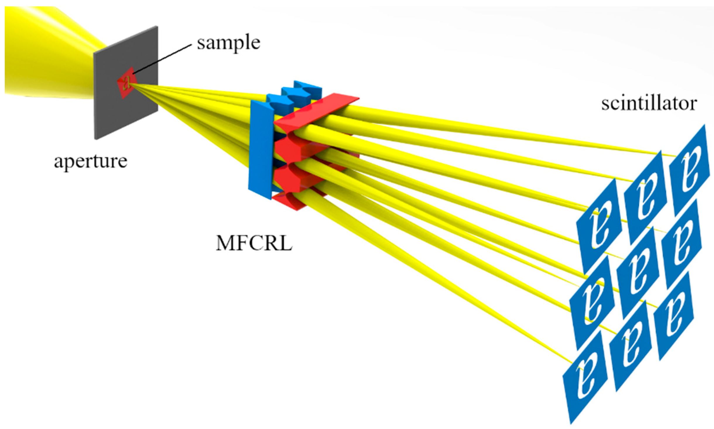
2.1. Multi Full-Field Microscopy

To decrease exposure times, it could be an option to increase the aperture of the objective CRL. Unfortunately, increasing the effective aperture is limited due to absorption at the outer parts of a CRL. Analogous arguments exist for other kinds of X-ray optics. As an alternative, we suggest using an array of CRLs to reduce the exposure time of cone-beam sources. In this case, the optical axes of the individual CRLs are not parallel to each other but slightly tilted in such a way that they meet in the center point of the FoV. Thus, the same part of the sample is imaged several times from slightly different directions. The multi full-field microscopy principle is shown in Figure 1, assuming proper sample illumination. A 3 × 3 array of slightly tilted objective lenses, a so-called multi-focus CRL (MFCRL), is imaging the FoV to the scintillator plane. The scintillator converts the X-rays to visible light, and this visible image is detected via a microscope objective on a CCD-detector (not shown in Figure 1). The multi full-field microscopy principle has obvious similarities with approaches towards tomography, where the sample has to be projected simultaneously from various different directions [13,14], which results in a decrease of the total exposure time for one tomograph [15]. In contrast to these methods, in multi full-field microscopy, the imaging objective lens is positioned between the sample and the detector, and the angles should be as small as possible to position as many images as possible side by side on the detector.
Due to small angles in X-ray optics, the Scheimpflug effect [16] can be neglected in the first approximation. The Scheimpflug effect describes the tilt of the focus plane when the objective plane and detector plane are not parallel to each other. For hard X-ray full-field microscopy at laboratory sources, this principle could reduce the necessary exposure times drastically. In the case of moderate magnifications, typically the complete detector area is not used in these setups. Thus, applying the multi full-field principle is feasible even with the detector existing in the system. Often 3 × 3 or even more images could be placed beside each other on the detector. Using multi full-field microscopy instead of conventional full-field microscopy, the number of photons gathered can be increased by a factor of n2 − 1 when using an n × n lens array. Thus, the signal to noise ratio (SNR) can be increased drastically.

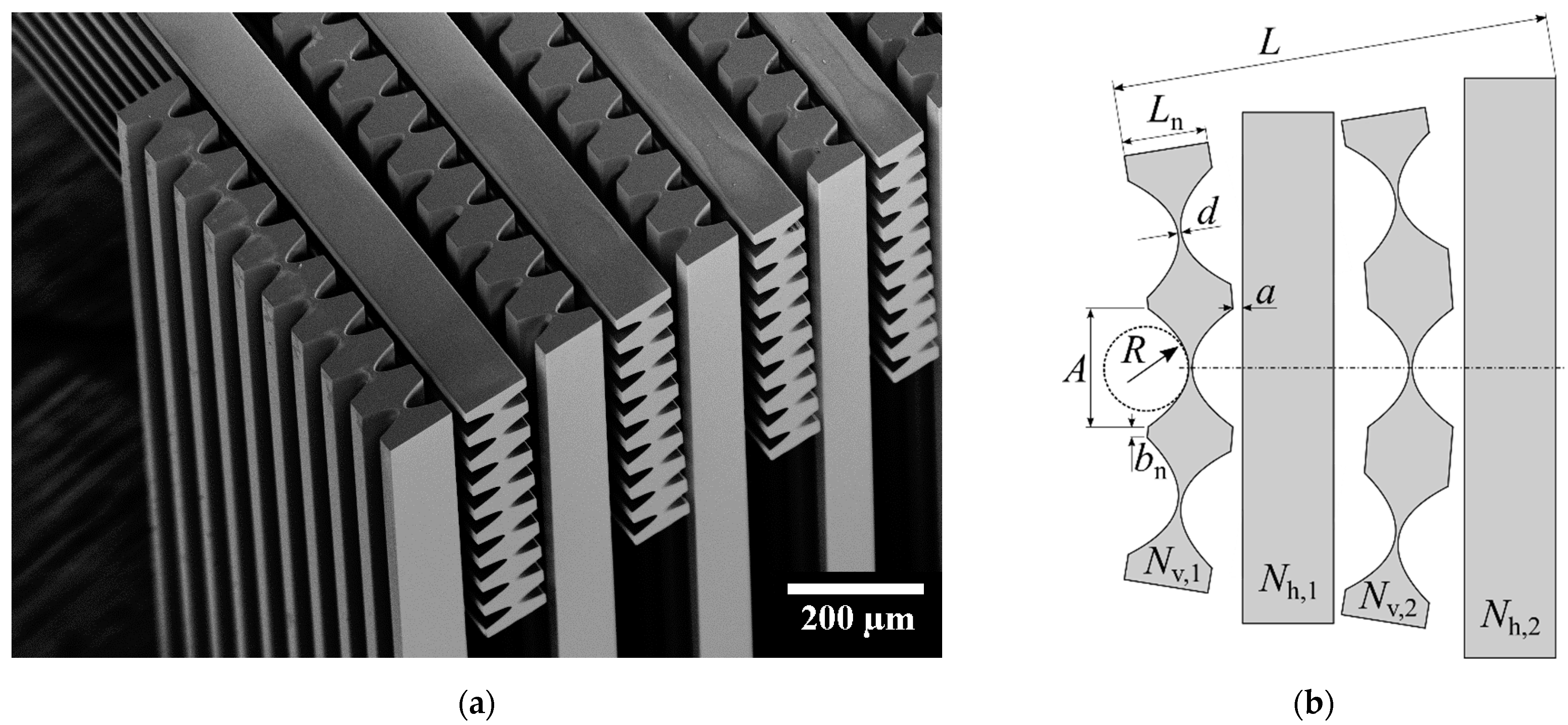
2.2. Multi-Lens Array Fabrication

A large effective aperture, of course, is also crucial when using the multi full-field principle. The effective aperture of a CRL is maximized when using suitable lens material showing low X-ray absorption. Most X-ray transparent materials for CRLs are low atomic Z-number materials such as lithium, beryllium, or carbon [17]. Lithium is very reactive with humidity in the air, and fabricating Be-CRLs via imprinting [18] limits the possible geometries of CRLs. In recent years, additive manufacturing processes that use direct laser exposure have been tested for the production of CRLs [19,20]. This manufacturing process is still slow [21] and, due to the voxel-wise exposure, provides quite rough surfaces compared to lithographic processes.
Using lithographic fabrication methods allows the fabrication of an aligned array of slightly tilted CRLs with high quality and precision. For these reasons, we fabricated multi-focus CRLs via deep X-ray lithography. Deep X-ray lithography is a crucial part of the LIGA technology (German acronym for lithography, electroplating, and molding), invented and developed at KIT/IMT [22,23]. It is used to structure a resist of up to several millimeters in height [24]. For CRLs, the resist mr-X (microresist technology GmbH, Berlin, Germany), an epoxy-based negative resist, is used. A rectangular layout area of 20 mm × 60 mm is exposed perpendicular to the substrate via an X-ray absorption mask. In this way, up to about 40 line focus CRLs with a height of up to 2 mm are fabricated in one exposure. After post-exposure bake and development, the CRLs are separated with a wafer saw. To fabricate point focus CRLs, two corresponding line focus CRLs are mounted under 90° in an interdigitated way (Figure 2). Currently, point focusing optics with apertures of up to 1.8 mm × 1.8 mm are fabricated.

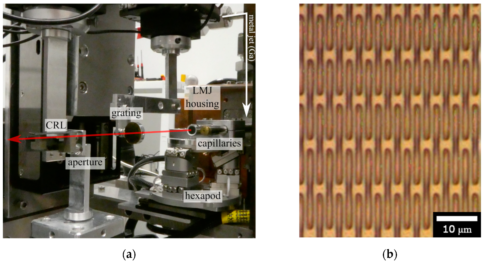
2.3. Microscopy Setup

To show the advantages of full-field microscopy with a multi-lens array, we present a proof-of-principle, which was done at a mid-energy setup using the 9.25 keV Ga Kα-line. The relatively low photon energy of 9.25 keV has been used, because no setup with higher photon energies was available. Of course, Fresnel zone plates would be better suited for this photon energies [25]. In our case, the 9 × 9 multi-focus CRL shown in Figure 2 was used. The individual CRLs are designed for an X-ray energy of 9.25 keV. They have all identical optical layout parameters. The object distance is designed to be 50 mm and the image distance to be 700 mm (measured to the entrance aperture of the CRL). With a total length of the CRL of L = 4.7 mm, a magnification of approximately 13.1 is achieved. The aperture of the Nv = 19 vertically focusing and Nh = 20 horizontally focusing lens elements varies, respectively, from A1 = 46 µm at the first element (i.e., Nv,1 and Nh,1) over A10 = 43.1 µm to A20 = 47.9 µm. This is referred to as Taille lens and allows for high spatial resolution as well as homogeneous image quality [26]. The average transmission of the CRL is 29%. At 24.2 keV, the average transmission of a suitable CRL (Nv = 136, Nh = 137) with the same focal length would even reach 53%. The theoretical diffraction limited resolution of the setup is bmin = λ/2NAeff = 0.5 µm, with the effective numerical aperture NAeff. The complete parameters of the CRL used are summarized in Tables S1 and S2 in the Supplementary Material. The different N for the two half lenses is used to minimize astigmatism. Therefore, the radius of the horizontally focusing lens elements Rh = 6.09 µm is slightly larger than the radius of the vertically focusing lens elements Rv = 6.08 µm. The parameter b1 is 27 µm, i.e., for the first lens element, and increases continuously for the next lens elements. The air gap a = 30 µm between neighboring lens elements is constant. The lenses are designed in such a way that the center-to-center distance of adjacent images on the scintillator is 956 µm.
The setup at LRM (Würzburg) uses a liquid MetalJet (Excillum, Kista, Sweden) source. The spectrum of this source and the imaging efficiency in single lens full-field microscopy are discussed in detail in [10]. As an objective lens, the above-described multi-focus CRL was used. A photo of the setup is shown in Figure 3a. In the upper right corner, the position of the metal jet is indicated by a white arrow. In front of the Be-window (not visible) in the copper housing, a 7-axis manipulator for the condenser alignment (1 translation + 6-axis hexapod) is placed. The polycapillary (XOS polycapillary, length 155 mm, entrance angle 0.95° and exit angle 0.3°, focus size 100 µm) is used for proper sample illumination. The sample is an absorption grating (period 2.4 µm, 10 µm gold thickness, microworks GmbH), which is shown in Figure 3b. For the measurements, a rectangular aperture (50 µm × 50 µm) was placed as near as possible to the sample, i.e., approximately 1.5 mm. It limits the field of view. Thus, this aperture prevents neighboring images on the detector plane from overlapping. The multi-focus CRL is placed 50 mm behind the sample and images the latter to the detector system, which is 700 mm away from the CRL’s entrance aperture. The detector system cannot be seen in Figure 3. It consists of a 50 µm thick LuAG:Ce (Crytur, Turnov, Czech Republic) scintillator, two filter-to-filter screwed Nikkor objective lenses (50 mm and 105 mm in infinity configuration), and a PCO.edge sCMOS detector with 2560 × 2160 pixels of 6.5 µm pixel edge length, resulting in a sensor format of 16.6 mm × 14 mm, respectively. This leads to an effective pixel size of 3.1 µm in the scintillator plane. With the magnification of approximately 13.1 in the X-ray optical part, the effective pixel size in the sample plane is about 240 nm.

3. Results

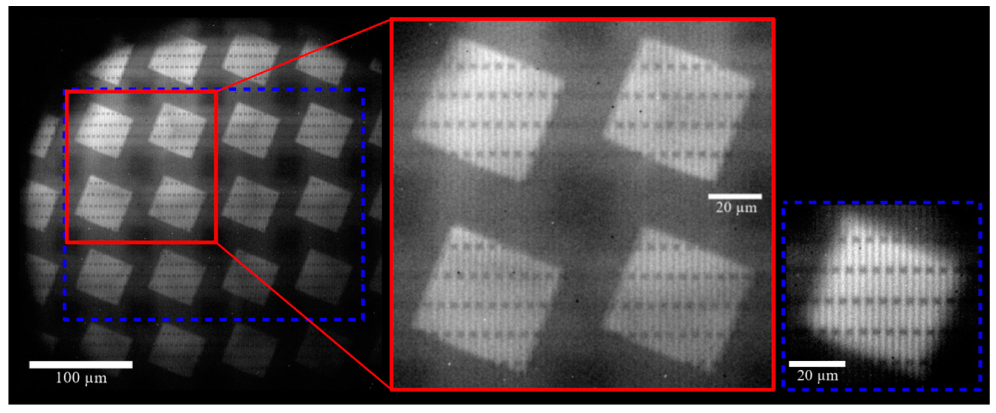
3.1. Measurement Results

The multiple images of the grating are shown in Figure 4. The exposure time was 400 s. The images are dark-field and flat-field corrected with the use of a background image taken with no sample in the beam. The areas outside the illumination cone of the poly-capillary are black. Inside of the tilted 50 µm × 50 µm aperture, gold lamellas are shown in gray (magnified section in Figure 4, middle). It can be seen by the different vertical position of horizontally oriented structures that the FoV is slightly different for each CRL. This deviation could be overcome by a more exact alignment of the distance between sample and multi-focus CRL, leading to a larger effective FoV. The number of images on the detector here is limited by the diameter of the illumination cone of the polycapillary. The detector size would have allowed all 9 × 9 images of the multi-focus CRL to be taken. Each of the 9 × 9 sub-images of the sample is generated by a different single sub-CRL of the multi-CRL array.
Out of the 9 × 9 CRL array, a set of 3 × 4 images is used to create one image of the effective FoV with high contrast (Figure 4, right). The contrast of the 2.4 µm period gold lines in the final image was 12%, so the gratings’ period was clearly resolved.
As expected, the total number of photons detected by the detector was increased by a factor of the number of single images produced by the CRL array. The SNR of the image summed up from twelve single images increased by a factor of 2.5 compared to a single image of the sample (Figure 5). As the stochastic noise decreases with the root of the increase in intensity, theoretically a reduction by a factor of nearly 3.5 would be possible. In the experiment, the illumination was not completely homogeneous, and part of the radiation was lost due to rays passing through the material blocks between the CRLs, resulting in a lower improvement of the SNR. Of course, instead of increasing the SNR by a factor of 2.5, one could instead decrease exposure time by a factor of 6.25.

3.2. Simulation Results

Between the individual images of the field of view, the background should be dark or show some stray light, because the FoV was stopped down. In the real measurements, however, clear structures can be seen between the individual images of the FoV. To understand these structures, beam tracking simulations were performed with the commercial software OpticStudio (Zemax LLC, Kirkland, WA, USA). The measurement setup was simulated true to scale taking into account the aperture, the grating as a sample, and the illumination with the polycapillary. The results are shown in Figure 6. There is an excellent agreement with the measured data. By tracing the path of individual rays through the multi-focus CRL, the origin of the structured background could be clarified. The background is caused by rays that have partially or completely passed through the lens material in between the individual CRLs on their way through the multi-focus CRL (Figure 7). Since the sample illumination is also at wide angles, some rays only partially pass through a CRL and therefore do not contribute to the desired image. The structures in the background are caused by the fact that there are rays that have passed through a significantly different number of vertical or horizontal single lens elements. Such rays provide an image of the sample that appears distorted in one direction in space, similar to imaging with an astigmatic lens. The structured background disappears when an absorbing wall with windows for each CRL is placed in front of and behind the multi-focus CRL in the simulation. In this case, all rays that have not passed through the optics correctly are blocked out.
When the intensities of the 25 individual images are superimposed and summed up in the correct position, a low-noise image of the sample is obtained as expected (Figure 6b). The average intensity in the summed image of the sample was 22.8 times higher than in the individual images. Theoretically one would have expected a factor of 25. The deviation is due to the fact that the four outermost images are clearly vignetted due to the illumination limited by the polycapillary and therefore contain less intensity. The intensity noise in the image is reduced by a factor of 4.8 in the summed image in the simulation compared to the individual images. This corresponds to the theoretical value, since the stochastic noise decreases with the root of the increase in intensity.

4. Discussion

For the first time, an X-ray full-field microscope at a laboratory source was built using a multi-focus CRL objective. Making use of the 9.25 keV Ga Kα-line, several non-overlapping images of a 2.4 µm period absorption grating were generated with a contrast of 12%. The gain in contrast by a factor of 2.5 when imaging the same FoV with a 4 × 3 CRL array from slightly different directions was shown. The theoretical factor of 3.5 was not achieved due to not completely homogeneous illumination as well as rays passing through the material blocks between the CRLs. Using ray-tracing simulations, it could be shown that the structured image background between the individual images is created by those rays that have not completely passed through a single CRL but have exited laterally before passing through the entire lens.
Given this positive proof-of-principle at X-ray energies below 10 keV, a setup for multi full-field microscopy at 24.2 keV is planned. This can be done by making use of the 24.2 keV In Kα-line, which is possible with, for example, an Indium alloy Excillum MetalJet source [27]. The setup presented here (Section 2.3) contains an alloy of 95% Ga and 5% In, resulting in an approximately 130 times less intense 24.2 keV In Kα-line, compared to the 9.25 keV Ga Kα-line [4]. For this reason, the 24.2 keV In Kα-line was not investigated for this proof-of-principle. The multi-focus CRLs could be improved by adding front and back apertures blocking all rays that did not pass the lenses correctly. Further improving the multi full-field microscopy method includes automated merging of the single images as well as making use of partly overlapping images.

Supplementary Materials

The following are available online at https://www.mdpi.com/article/10.3390/app11167234/s1, Table S1: Summarized parameters of the used MFCRL, Table S2: All aperture sizes of the used MFCRL. The aperture Ai is the same for lens element Nv,i and Nh,i, i.e., for the ith vertically and ith horizontally focusing lens element.

Author Contributions

Conceptualization, A.O., D.M. and A.L.; Formal analysis, A.O. and A.L.; Funding acquisition, C.F., J.M. and A.L.; Investigation, A.O., D.M., C.F., A.B., J.M. and A.L.; Methodology, A.O., C.F. and A.L.; Project administration, J.M. and A.L.; Resources, A.O., D.M., C.F., A.B., J.M. and A.L.; Supervision, J.M. and A.L.; Validation, A.O., D.M., C.F., A.B., J.M. and A.L.; Writing—original draft, A.O., D.M. and A.L.; Writing—review and editing, C.F., A.B. and J.M. All authors have read and agreed to the published version of the manuscript.

Funding

This research received no external funding.

Acknowledgments

We thank the Karlsruhe Nano Micro Facility (KNMF) for the fabrication of the polymer X-ray optics and microworks GmbH for providing the sample grating. We further acknowledge the support of the Karlsruhe School of Optics and Photonics (KSOP, financed by the Ministry of Science, Research and the Arts of Baden-Württemberg as part of the sustainability financing of the projects of the Excellence Initiative II) as well as the support of the KIT-Publication Fund of the Karlsruhe Institute of Technology.

Conflicts of Interest

The authors declare no conflict of interest.

References

  1. Hecht, E. Optik, 7th ed.; Walter de Gruyter GmbH: Berlin, Germany, 2018. [Google Scholar]
  2. Baumbach, S.; Kanngießer, B.; Malzer, W.; Stiel, H.; Wilhein, T. A laboratory 8 keV transmission full-field X-ray microscope with a polycapillary as condenser for bright and dark field imaging. Rev. Sci. Instrum. 2015, 86, 083708. [Google Scholar] [CrossRef] [PubMed]
  3. Attwood, D. Soft X-Rays and Extreme Ultraviolet Radiation: Principles and Applications; Cambridge University Press: Cambridge, UK, 2007. [Google Scholar]
  4. Fella, C. High-Resolution X-ray Imaging Based on a Liquid-Metal-Jet-Source with and without X-ray Optics. Ph.D. Thesis, Julius-Maximilians-Universität Würzburg, Wurzburg, Germany, 2016. [Google Scholar]
  5. Niese, S.; Krüger, P.; Kubec, A.; Braun, S.; Patommel, J.; Schroer, C.G.; Leson, A.; Zschech, E. Full-field X-ray microscopy with crossed partial multilayer Laue lenses. Opt. Express 2014, 22, 20008–20013. [Google Scholar] [CrossRef] [PubMed] [Green Version]
  6. Seim, C.; Baumann, J.; Legall, H.; Redlich, C.; Mantouvalou, I.; Blobel, G.; Stiel, H.; Kanngießer, B. Laboratory Full-Field Transmission X-ray Microscopy. Proc. SPIE 2012, 8678, 867808. [Google Scholar]
  7. Lengeler, B.; Schroer, C.G.; Richwin, M.; Tümmler, J. A microscope for hard X-rays based on parabolic compound refractive lenses. Appl. Phys. Lett. 1999, 74, 3924–3926. [Google Scholar] [CrossRef] [Green Version]
  8. Schroer, C.G.; Günzler, T.F.; Benner, B.; Kuhlmann, M.; Tümmler, J.; Lengeler, B.; Rau, C.; Weitkamp, T.; Snigirev, A.; Snigireva, I. Hard X-ray full field microscopy and magnifying microtomography using compound refractive lenses. Nucl. Instrum. Meth. A 2001, 467–468, 966–969. [Google Scholar] [CrossRef]
  9. Serebrennikov, D.A.; Dudchik, Y.I.; Barannikov, A.A.; Klimova, N.B.; Snigirev, A.A. X-ray microscope with refractive X-ray optics and microfocus laboratory source. Proc. SPIE 2017, 10387, 103870H. [Google Scholar]
  10. Fella, C.; Balles, A.; Hanke, R.; Last, A.; Zabler, S. Hybrid setup for micro- and nano-computed tomography in the hard X-ray range. Rev. Sci. Instrum. 2017, 88, 123702. [Google Scholar] [CrossRef]
  11. Polikarpov, M.; Snigireva, I.; Morse, J.; Yunkin, V.; Kuznetsov, S.; Snigirev, A. Large-acceptance diamond planar refractive lenses manufactured by laser cutting. J. Sync. Rad. 2014, 22, 23–28. [Google Scholar] [CrossRef] [PubMed]
  12. Murray, K.T.; Pedersen, A.F.; Mohacsi, I.; Detlefs, C.; Morgan, A.J.; Prasciolu, M.; Yildirim, C.; Simons, H.; Jakobsen, A.; Chapman, H.; et al. Multilayer Laue lenses at high X-ray energies: Performance and applications. Opt. Express 2019, 27, 7120–7138. [Google Scholar] [CrossRef]
  13. Chawla, A.S.; Boyce, S.; Washington, L.; McAdams, H.P.; Samei, E. Design and Development of a New Multi-Projection X-Ray System for Chest Imaging. IEEE Trans. Nucl. Sci. 2014, 56, 36–45. [Google Scholar] [CrossRef] [PubMed] [Green Version]
  14. Samei, E.; Stebbins, S.A.; Dobbins, J.T.; Lo, J.Y. Multiprojection Correlation Imaging for Improved Detection of Pulmonary Nodules. Am. J. Roentgenol. 2007, 188, 1239–1245. [Google Scholar] [CrossRef]
  15. Villanueva-Perez, P.; Pedrini, B.; Mokso, R.; Vagovic, P.; Guzenko, V.; Leake, S.; Willmott, P.R.; David, C.; Chapman, H.N.; Stampanoni, M. Coherent Hard X-ray Multiprojection Imaging. Microsc. Microanal. 2018, 24, 50–51. [Google Scholar] [CrossRef] [Green Version]
  16. Scheimpflug, T. Improved Method and Apparatus for the Systematic Alteration or Distortion of Plane Pictures and Images by Means of Lenses and Mirrors for Photography and for other purposes. GB Patent No. 1196, 16 January 1904. [Google Scholar]
  17. Henke, B.L.; Gullikson, E.M.; Davis, J.C. X-ray interactions: Photoabsorption, scattering, transmission, and reflection at E = 50 − 30,000 eV, Z = 1 − 92. At. Data Nucl. Data Tables 1993, 54, 181–342. [Google Scholar] [CrossRef] [Green Version]
  18. Roth, T.; Alianelli, L.; Lengeler, D.; Snigirev, A.A.; Seiboth, F. Materials for X-ray refractive lenses minimizing wavefront distortions. Mrs. Bull. 2017, 42, 430–436. [Google Scholar] [CrossRef] [Green Version]
  19. Petrov, A.K.; Bessonov, V.O.; Abrashitova, K.A.; Kokareva, N.G.; Safronov, K.R.; Barannikov, A.A.; Ershov, P.A.; Klimova, N.; Lyatun, I.I.; Yunkin, V.A.; et al. Polymer X-ray refractive nano-lenses fabricated by additive technology. Opt. Express 2017, 25, 14173–14181. [Google Scholar] [CrossRef] [PubMed] [Green Version]
  20. Sanli, U.T.; Ceylan, H.; Bykova, I.; Weigand, M.; Sitti, M.; Schütz, G.; Keskinbora, K. 3D Nanoprinted Plastic Kinoform X-Ray Optics. Adv. Mater. 2018, 30, 1802503. [Google Scholar] [CrossRef] [PubMed] [Green Version]
  21. Ristok, S.; Thiele, S.; Toulouse, A.; Herkommer, A.M.; Giessen, H. Stitching-free 3D printing of millimeter-sized highly transparent spherical and aspherical optical components. Opt. Mater. Express 2020, 10, 2370–2378. [Google Scholar] [CrossRef]
  22. Saile, V.; Wallrabe, U.; Tabata, O.; Korvink, J.G. Advanced Micro & Nanosystems. In LIGA and Its Applications; Wiley-VCH: Hobroken, NJ, USA, 2009; Volume 7. [Google Scholar]
  23. LIGA-Process. Available online: www.x-ray-optics.de/index.php/en/10-hauptkategorie-en/208-liga-process (accessed on 6 May 2021).
  24. Nazmov, V.; Reznikova, E.; Mohr, J.; Voigt, A. A method of mechanical stabilization of ultra-high-AR microstructures. J. Mater. Process. Tech. 2016, 231, 319–325. [Google Scholar] [CrossRef]
  25. Mohacsi, I.; Vartiainen, I.; Rösner, B.; Guizar-Sicairos, M.; Guzenko, V.; McNulty, I.; Winarski, R.; Holt, M.; David, C. Intarlaced zone plate optics for hard X-ray imaging in the 10 nm range. Sci. Rep. 2017, 7, 43624. [Google Scholar] [CrossRef] [Green Version]
  26. Marschall, F.; Last, A.; Simon, M.; Vogt, H.; Mohr, J. Simulation of aperture-optimised refractive lenses for hard X-ray full field microscopy. Opt. Express 2016, 24, 10880–10889. [Google Scholar] [CrossRef] [PubMed] [Green Version]
  27. Excillum, A.B. MetalJet-Technology-ENG-2019-06-14-Screen. Available online: www.excillum.com/download/7882 (accessed on 20 June 2020).
Figure 1. Sketch of the multi full-field microscopy principle. The multi-focus CRL (MFCRL) images the sample with a certain magnification to the scintillator plane.
Applsci 11 07234 g001
Figure 2. (a) SEM image of a 9 × 9 CRL array used for multi full-field X-ray microscopy. (b) Parameters of a multi-focus CRL with physical aperture A, radius R in the apex of the parabola, total length L of the CRL, length Ln of a single lens element, thickness d of the web, air gap a between two adjacent lens elements, and width bn between two entrance apertures.
Applsci 11 07234 g002
Figure 3. (a) Liquid MetalJet (LMJ) setup at the LRM in Würzburg. In the upper right corner, the position of the metal jet is indicated by a white arrow. The Be exit window in the LMJ copper housing is hidden by two capillaries mounted on a hexapod. The left capillary is a polycapillary, used for illuminating an absorption grating (sample). For imaging the grating, an aperture (50 µm × 50 µm) is placed as near as possible to the grating. (b) Light microscopy image of the absorption grating (period 2.4 µm, 10 µm gold thick-ness, microworks GmbH) used as sample. The small differences in contrast originate from the light microscope illumination, not from the absorption grating.
Applsci 11 07234 g003
Figure 4. Multi full-field X-ray microscopy image of an absorption grating stopped down using a tilted 50 µm × 50 µm aperture. The image is dark-field and flat-field corrected. The picture section in the middle includes four images of the sample. For increasing the image quality, twelve images of a 3 × 4 array are summed up (right).
Applsci 11 07234 g004
Figure 5. Comparing the intensities (c) of one of the twelve images in Figure 4 ((a) blue line, right axis) with the overlay of the twelve images ((b) black line, left axis).
Applsci 11 07234 g005
Figure 6. (a) Ray-tracing simulation of the setup in Figure 3. (b) For increasing the image quality, the 25 individual images are relocated to a center position and summed up; both images are normalized to maximum intensity, and the axes units are in pixels.
Applsci 11 07234 g006
Figure 7. Sketch of a 3 × 3 MFCRL array with a sample 1; the rays demonstrate a ray 2 regularly passing the array; a ray 3 passing the horizontally focusing lens elements but missing the vertically focusing elements; and a ray 4 passing the vertically focusing lens elements but missing the horizontally focusing elements.
Applsci 11 07234 g007
Publisher’s Note: MDPI stays neutral with regard to jurisdictional claims in published maps and institutional affiliations.

