
Wheel Flats in the Dynamic Behavior of Ballasted and Slab Railway Tracks


Construct, Faculty of Engineering, University of Porto, Rua Dr. Roberto Frias, s/n, 4200-465 Porto, Portugal
Appl. Sci. 2021, 11(15), 7127; https://doi.org/10.3390/app11157127
Submission received: 22 June 2021
/
Revised: 20 July 2021
/
Accepted: 28 July 2021
/
Published: 2 August 2021
(This article belongs to the Topic Dynamical Systems: Theory and Applications)
Abstract
:Wheel flats induce high-impact loads with relevance for the safety of the vehicle in operation as they can contribute to broken axles, hot axle boxes, and damaged rolling bearings and wheels. The high loads also induce damage in the track components such as rails and sleepers. Although this subject has been studied numerically and experimentally over the last few years, the wheel flat problem has focused on ballasted tracks, and there is a need to understand the phenomena also for slab tracks. In this research, a numerical approach was used to show the effects of the wheel flats with different geometric configurations on the dynamic behavior of a classical ballasted track and a continuous slab track. Several wheel flat geometries and different vehicle speeds were considered. The nonlinear Hertzian contact model was used because of the high dynamic variation of the interaction of the load between the vehicle and the rail. The results evidenced that, for the same traffic conditions, the dynamic force was higher on the slab track than on the ballasted one, contrary to the maximum vertical displacement, which was higher on the ballasted track due to the track differences regarding the stiffness and frequency response. The results are useful for railway managers who wish to monitor track deterioration under the regulatory limits.
1. Introduction
Railway tracks can be categorized into ballasted and ballastless or slab systems. Ballasted tracks are composed of rails supported by sleepers that are placed over a ballast layer. The rails are connected to the sleepers by fastening systems. The pads, together with the ballast, the sub-ballast layers, and the foundation, provide elasticity to the system.
Regarding slab track systems, the International Union of Railways [1] considers seven different families:
- Systems without punctual fastening of the rail;
- Systems with punctual fastening of the rail and independent stretches of rail;
- Systems with punctual fastening of the rail on sleepers incorporated into the structure by infill concrete;
- Systems with punctual fastening of the rail on sleepers incorporated into the structure by vibration;
- Systems with punctual fastening of the rail on sleepers laid and anchored on a supporting structure;
- Systems with punctual fastening of the rail on sleepers separated from the supporting structure by a resilient level;
- Systems with punctual fastening of the rail on prefabricated slabs.
Slab track systems may be interesting for high-speed and heavy traffic lines. In Europe, one of the most used slab systems is Rheda 2000, a continuous track, which belongs to the third family. Due to this reason, in this research, a continuous slab track system was studied.
Wheel flats are the most typical type of wheel defects during long-term train operation. These defects induce high-impact loads on the railway infrastructure, which causes significant damage to both vehicles and tracks, such as broken axles, hot axle boxes, damaged rolling bearings, and cracks on the wheels, the rails, and the sleepers. Furthermore, high levels of noise and excessive vibration are generated by this type of wheel defect. Wheel flats are mainly due to anomalous wear of the wheel due to sudden braking or due to insufficient adhesion force between the wheel and the rail [2].
Although this subject has been studied both numerically and experimentally over the last few years by several researchers, the wheel flat problem remains of current interest because the vehicle speed is increasing, contributing for higher dynamic loads (due to speed and irregularities) on the tracks. Furthermore, there are limited studies on the effect of wheel flats on slab tracks. Wheel flats induce high-impact loads, which should be controlled and limited to maximize the life of the system. In recent years, many different methods for measuring in situ wheel defects have been proposed. For instance, Shim et al. [3] tested two vibration signal processing methods for the detection and diagnosis of wheel flats: the cepstrum analysis method combined with order analysis and the cross-correlation analysis method combined with order analysis. Mosleh et al. [4] concluded that the envelope spectrum analysis is a capable tool and a cost-effective method that can be used to detect wheel flats along with the flat impact frequency for different train speeds in real-world conditions. Mosleh et al. [5] ran a 3D numerical simulation of the train track dynamic response to the presence of wheel flats to identify the type of sensors that can be adopted in wayside wheel flat detection, but this study focused only on ballasted tracks. The EU-funded MAXBE Project (http://www.maxbeproject.eu/, accessed on July 2021), which focused on detecting wheel flats and axle bearing failure modes at an early stage [6], also presented relevant methodologies for wayside and on-board vehicle monitoring. To detect and diagnose wheel defects, the problem has to be fully understood both experimentally and numerically. The most relevant and recent contributions to the wheel flat problem [7,8,9,10,11,12,13,14,15,16,17,18,19] focused on ballasted tracks, and studies on slab track systems are lacking.
The main objective of this paper was to study and compare the effects of wheel flats with different geometrical configurations on the dynamic behavior of both ballasted and slab systems through a numerical approach. To fulfill this objective, numerical studies were performed in the 2D time domain. The scenarios in terms of vehicle speed and flat geometry were considered exceptional, thus not occurring in common situations, as this was a numerical study. For that reason, there were no real measurements corresponding to the analyzed scenarios for the validation of these critical scenarios. However, prior to this study, the numerical models used were previously calibrated and validated for other traffic conditions, which gave us confidence about the obtained results.
2. Dynamic Models for Coupled Vehicle–Track Systems
In this section, a review of 2D track and vehicle models for time domain calculations is described, as well as the wheel–rail interaction model. A 2D model was used because, for the numerical type of analysis to be performed, a 3D model would lead to a very high computation and time consumption.
2.1. Track Model
2.1.1. Ballasted Track
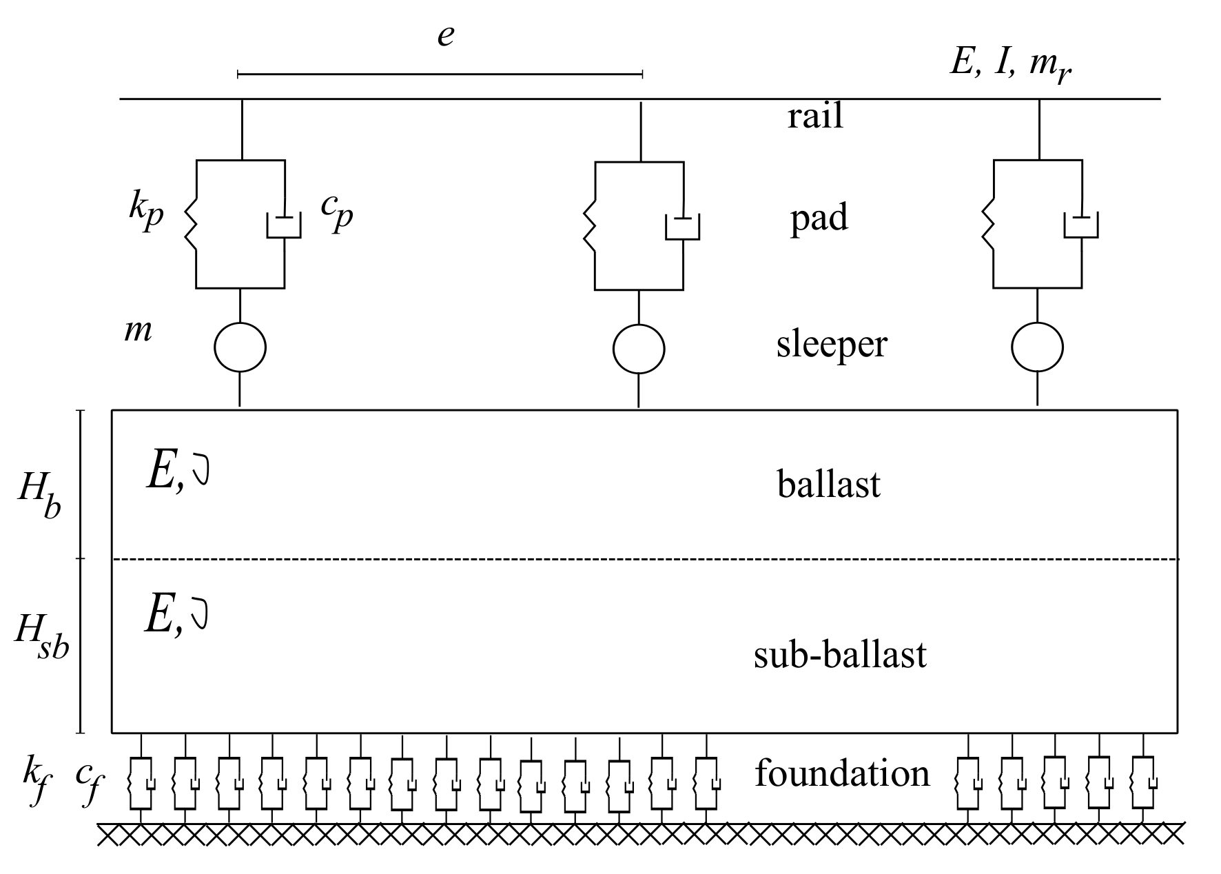
A ballasted rail track is composed of the rails, pads, sleepers, ballast, and sub-ballast placed on a foundation. In the 2D calculations, the rail was modeled by Euler–Bernoulli beam elements discretely supported on sleepers. The Timoshenko beam element may also be used, but according to several studies, this type of element does not influence the track response for the frequency range of the analysis. In the present study, the pad placed between the rail and the sleeper was represented by a spring in parallel with a dashpot with linear behavior, which is a simplified approach, as pads and granular materials present nonlinear material behavior. This nonlinearity was not contemplated in this research, because combining the material nonlinearity with the dynamic calculations increases the complexity of the problem, and it is very time consuming. The sleepers, usually spaced on ballasted tracks at 0.60 m, were simulated by punctual masses. In 2D ballasted tracks models, the granular materials may be represented by discrete or continuous models. Discrete modeling has been adopted by several authors such as [20,21,22,23], among others. Continuous models of the granular layers are defined by finite plane stress elements to simulate the longitudinal continuity of the layers. This approach was used by [24,25,26,27,28]. In the present research, the continuous model as presented in Figure 1 was used, because the continuity of granular layers plays an important role in the dynamic behavior of the track.
In Figure 1, as well as in the whole paper, the parameters are: E, elasticity modulus; I, the moment of inertia of the cross-section of the rail; , Poisson ratio; , area of the cross-section of the rail; , mass of the rail per meter; , stiffness of the pad; , damping of the pad; m, sleepers’ mass; e, spacing between consecutive sleepers; , thickness of the ballast layer; , thickness of the sub-ballast layer; , stiffness of the foundation; , damping of the foundation.
2.1.2. Slab Track
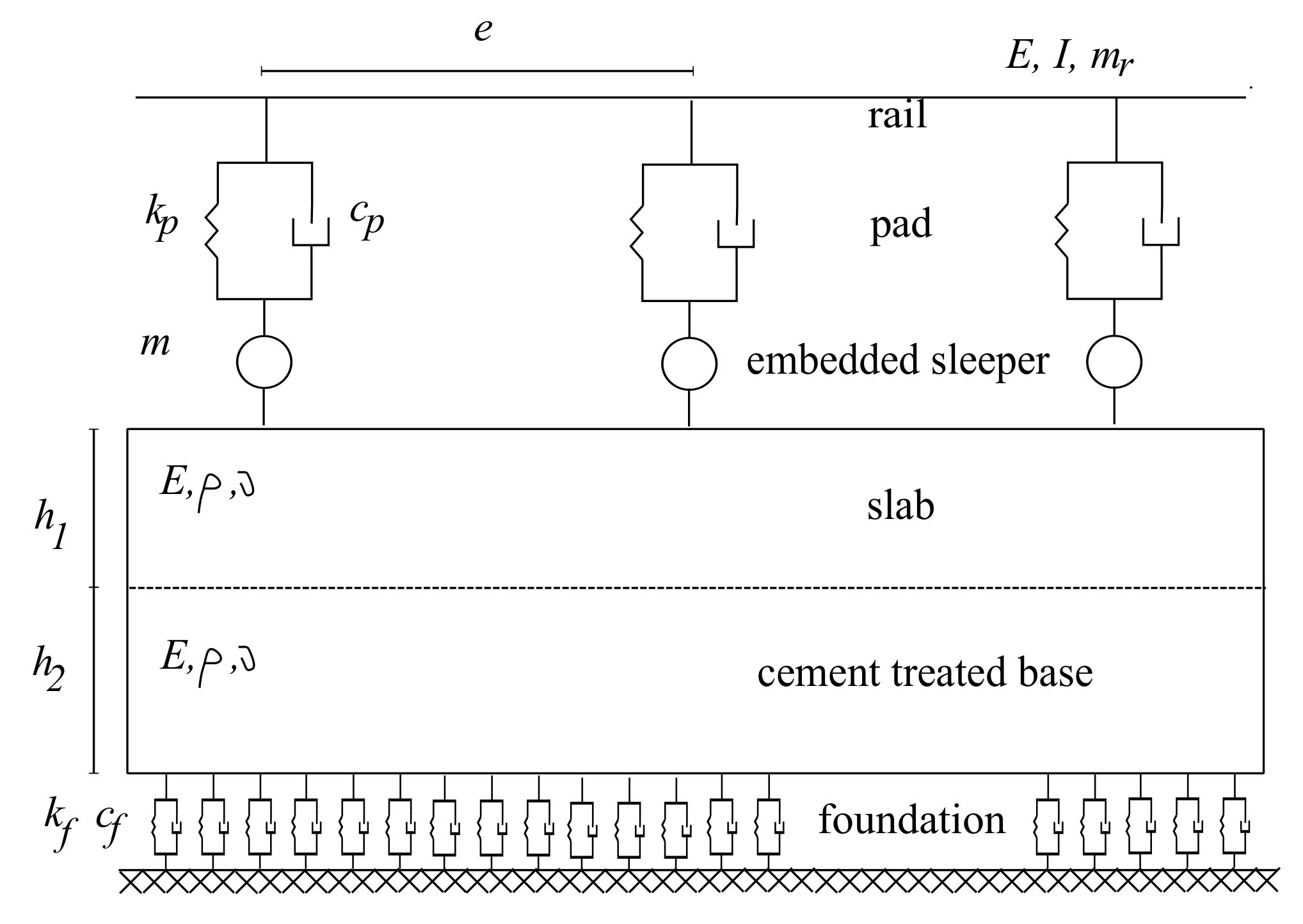
The continuous slab track under analysis consisted basically of a rigid bearing concrete structure, with the appropriate thickness and width, placed on a cement-treated base. The structure comprised fastening systems, whose primary function was to fix the rail into the right geometrical position. The track elasticity was essentially provided by the pads, which were the elastic elements of the system and were placed between the rail and the slab.
In Figure 2, a 2D model for this type of track is presented. The symbology is similar to the one presented on p. 3 plus: , density; , the thickness of the slab; , the thickness of the cement-treated base; L, the width of the cement-treated base.
With regard to the type of elements, the foundation was defined by a set of springs in parallel with dashpots, uniformly distributed without any longitudinal interaction. The cement-treated base layer and the concrete slab were modeled by eight-node plane-stress elements. The sleepers were simulated as punctual masses. The pads were discrete elements, and their mechanical behavior was characterized by a spring and a damper in parallel. With regard to the rail, this component was defined by Euler–Bernoulli beam elements.
2.2. Vehicle Model
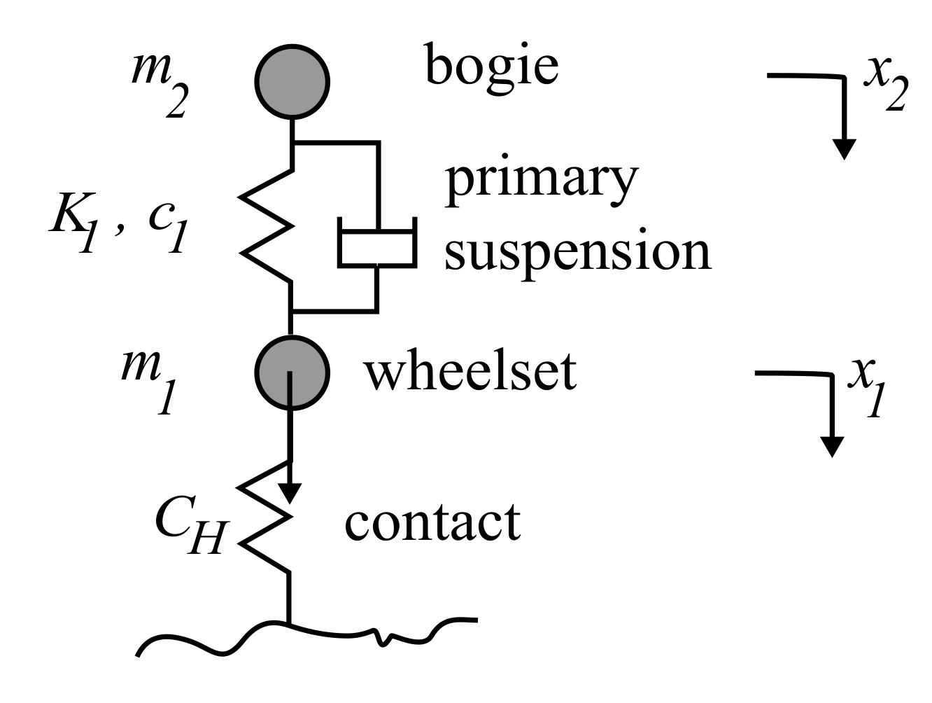
Supposing the load to be symmetrically distributed on the two rails, a quarter bogie model, as the one indicated in Figure 3, may be used to evaluate the dynamic load on the tracks and the corresponding track response. This vehicle model was defined by the wheel set and the bogie masses ( and , respectively) and by the primary suspension represented by a linear spring () in parallel with a dashpot (). In this study, the wheel set was considered to be rigid, which was a simplification, because more sophisticated vehicle models that consider the flexural modes of the wheel set would provide greater complexity to the calculations that already consider the nonlinear contact between the wheel and the rail. The nonlinear contact stiffness is represented by .
Two degrees of freedom were considered in this model: the vertical displacements of the wheel set () and the bogie (). More complex models such as the half bogie model or the half vehicle model in 2D analysis or a 3D vehicle model should be used when evaluating passenger comfort and vehicle vibrations [29].
2.3. Wheel Flat Modeling
The most common defects of vehicle wheels are corrugation and flats. The first one is more or less a regular phenomena, and it may be characterized by sinusoidal expressions or by Fourier series. With regard to the second defect, flats with no wear at the corner edges, i.e., a newly formed defect, consist of a geometric chord on the circumference of the wheel. Newly formed or fresh flats appear as a result of wheel-locking due to brake action.
For flats with no wear or rounded corners, the depth of the defect d can be related to its length l and the wheel radius r, as expressed by Equation (1). By solving this equation for d, the flat depth can be evaluated by Equation (2).
disregarding , since d is a very small value.
For the geometrical definition of wheel flats with no wear, Wu and Thompson [10] proposed Equation (3).
where r is the radius of the wheel; l, the length of the flat; d, the depth of the flat.
However, in real situations, as the wheels of the train are subject to wear, the corners of the flat become rounded and the flat length tends to increase, forming a rounded flat.
Usually, it is very difficult to characterize the real shape of a rounded flat. In the absence of real wheels’ profiles, rounded corner flats can be defined by Equation (4) as proposed by [10].
Wheel flats can be modeled by transforming the wheel defect into an equivalent and spaced rail defect, over which runs a perfect wheel. This approach has been used by several authors such as [10,15,21,30].
To set up the equivalent rail/track defect, which corresponds to the wheel flat, the Haversine function may be used. This function is expressed in Equation (5). In this equation, z and x correspond respectively to the vertical and the longitudinal direction of the track.
2.4. Contact Model between the Wheel and the Rail
The interaction force between the wheel and the rail can be evaluated by contact theory. The wheel–rail contact is characterized in the vertical direction by its high stiffness. Pieringera et al. [16] studied the influence of contact modeling on simulated impact forces due to wheel flats and concluded that 2D and Hertzian contact models give rather similar results to the 3D model. In this study, to simulate the normal contact between two bodies with no tangential forces at the contact area, the nonlinear Hertzian model was adopted. The fundamental hypotheses of the Hertzian contact model were provided by [31,32].
The nonlinear contact load is given by Equation (6):
where x is the wheel vertical displacement; y, the rail displacement; z, the rail profile; , the Hertzian stiffness.
The resolution of the contact problem involves controlling the penetration of the wheel and the rail, through nonlinear global optimization methods, such as the penalty, the method of Lagrange multipliers, or the augmented Lagrangian method, whose formulations can be found in [33]. In this paper, the penalty method was used because, in general, the augmented Lagrangian method requires higher computational effort. Furthermore, the penalty method is usually more robust.
3. Numerical Study
3.1. Track Characteristics
In this study, the model for the ballasted track was 90 m long and consisted of 150 sleepers with the spacing equal to 0.60 m. It was composed by 1954 elements defined by 4813 nodes. The length of this model (L) was defined in order to avoid numeric wave reflection, which can appear in models with an insufficient track length, as a consequence of the finite dimension of the model.
The mechanical and geometrical properties of the track elements are presented in Table 1. Since a Euler–Bernoulli formulation was applied, the results were independent of the Poisson ratio.
In this table, the parameters are: E, elasticity modulus; I, the moment of inertia of the cross-section of the rail; , Poisson ratio; , the area of the cross-section of the rail; , the mass of the rail per meter; , the stiffness of the pad; , the damping of the pad; m, sleepers’ mass; e, spacing between consecutive sleepers; , the thickness of the ballast layer; , the thickness of the sub-ballast layer; , the stiffness of the foundation; , the damping of the foundation.
The two-dimensional model used for the slab system had a total length of m, and it was composed of 1954 elements defined by 4813 nodes. As the ballasted track model, also the slab one considered the longitudinal symmetry of the structure.
In Table 2, the geometrical and mechanical characteristics of the elements that composed the slab system are presented. The stiffness and damping considered for the pads corresponded to those adopted in high-speed rail lines in France, Italy, and the Madrid-Barcelona line in Spain [34]. The parameter values corresponded to the Rheda 2000 system’s characteristics. For the pads, two values for the vertical stiffness are presented. The first one refers to the static stiffness of the pad, . The second value represents the dynamic stiffness, . For the calculations, the dynamic stiffness was used. With respect to the values of the sub-ballast, the ballast layers, and the foundation, the parameters corresponded to those suggested by [35] for high-speed railway lines. The value of the foundation damping was set based on the research works [15,36].
In Table 2, the parameters are: E, elasticity modulus; I, the moment of inertia; , Poisson ratio; , the transversal area of the rail; , density; , the stiffness of the pad; , the damping of the pad; m, sleepers’ mass; e, spacing between consecutive sleepers; , the thickness of the slab; , the thickness of the cement-treated base; L, the width of the cement-treated base; , the stiffness of the foundation; , the damping of the foundation.
3.2. Train Characteristics
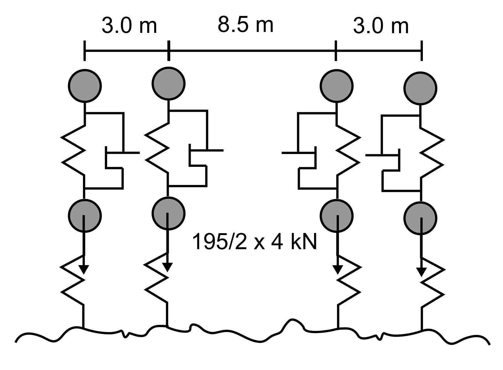
In this study, the ICE 2 train was selected in the numerical calculations. One axle of the quarter bogie model (Figure 4) was considered. The vehicle body and the secondary suspension were neglected because they contributed to the complexity of the calculations and were not relevant for the analysis of the contact forces. The ICE 2 mechanical parameters can be found in [37]. In the calculations, only a single defect was adopted in order to understand the influence of a flat on the dynamic track behavior without having the superposition of the effects.
Furthermore, all calculations were performed with the nonlinear contact model between the wheel and the rail, because it was expected that the variation of the dynamic load would be considerable. The considered contact stiffness was N/m, as indicated in the literature review.
In this paper, the track dynamic behavior was evaluated for a single newly formed wheel flat with different depths introduced to one wheel of the vehicle. A newly formed wheel flat was considered because, according to [13], fresh flats produce higher impact loads on the track than rounded flats.
3.3. Results and Discussion
3.3.1. Ballasted Track
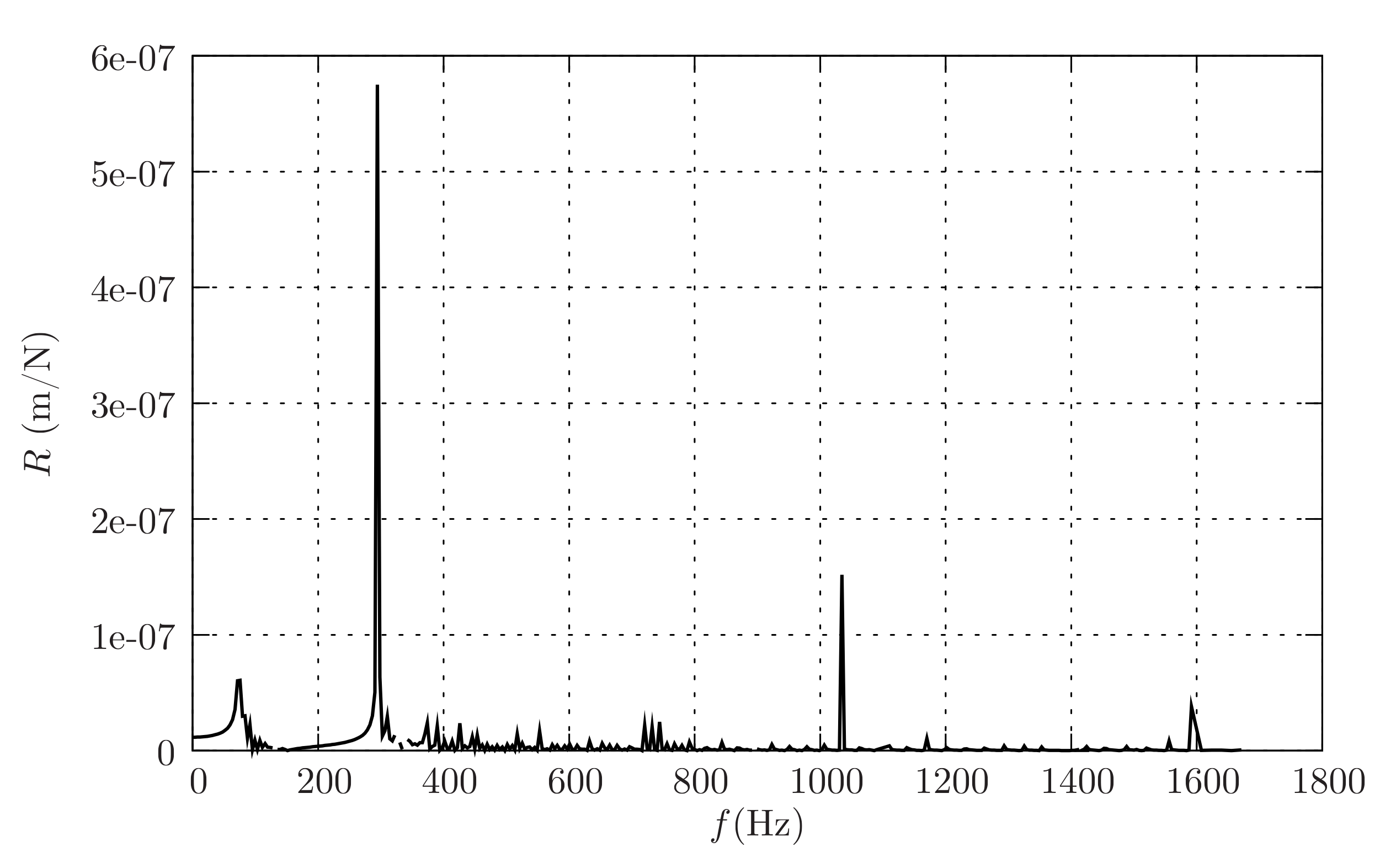
In Figure 5, the receptance of the ballasted track is shown.
The resonance frequencies that were more relevant for the vertical dynamic behavior of this ballasted track were 75, 230, and 1035 Hz, corresponding respectively to the ballast, rail, and pin–pin deformation. By looking up the magnitude of the receptance values, the flexibility of the track at the rail pad level was evident.
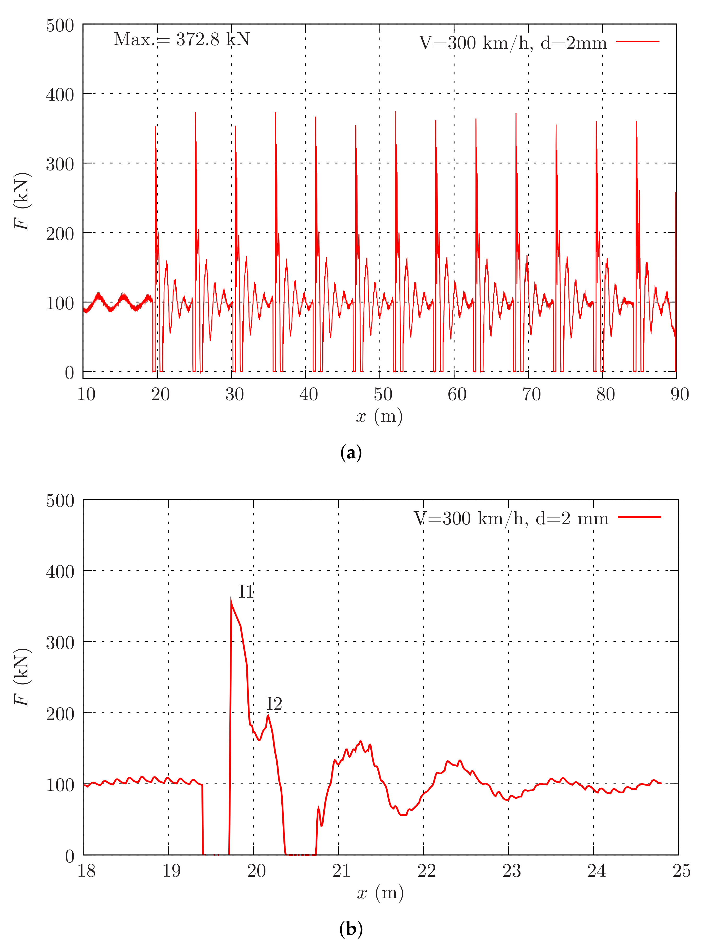
Regarding the effects of wheel flats on the ballasted track, the variation of the dynamic load along the ballasted track due to a wheel flat with a 2 mm depth running at 300 km/h is presented in Figure 6.
The variation of the dynamic load on the track due to the wheel flat obtained in this numerical study was similar to that found by other authors, such as [12,38,39].
By Looking at this figure, during the movement of the wheel flat on the track, two impact loads ( and ) appeared in addition to the occurrence of a loss of contact between the wheel and rail (Figure 6b).
At 300 km/h, the impact load was -times the static load, and the second impact force was -times that. The magnitude of these impact loads depends significantly on the train speed and strongly influences the track degradation process.
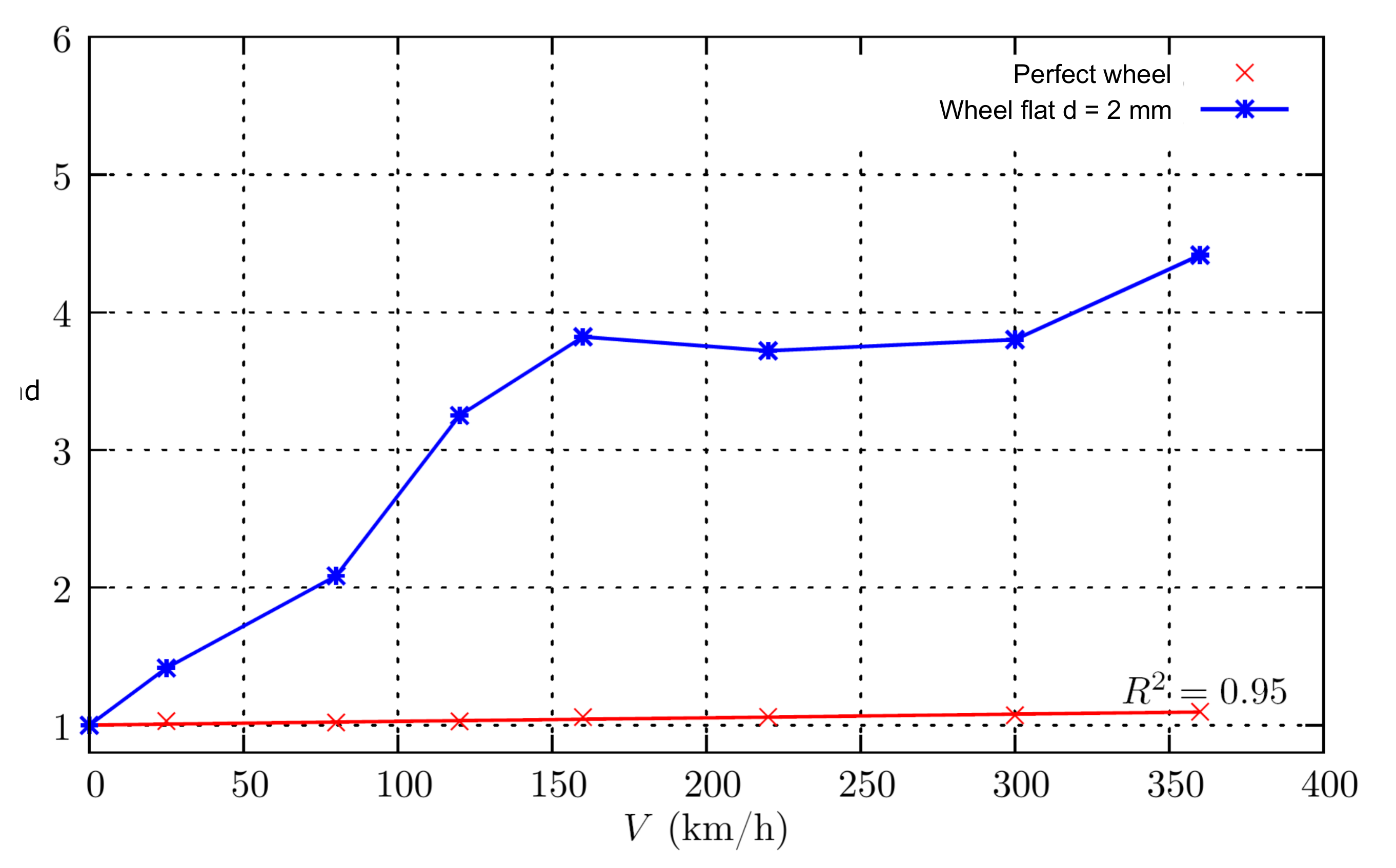
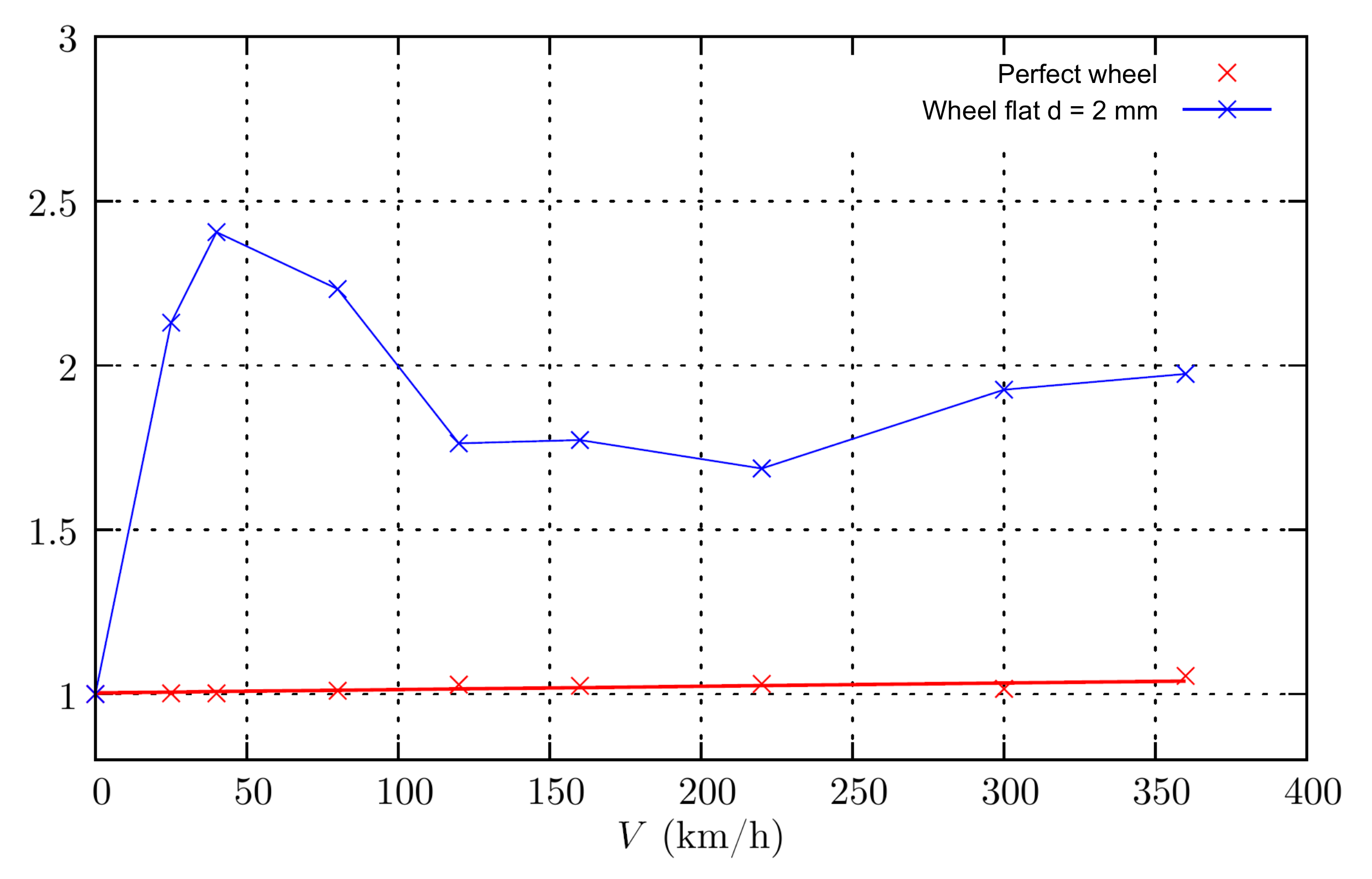
Figure 7 shows the evolution of the dynamic load amplification factor with the train speed, for the cases of a perfect wheel and a wheel flat. The dynamic amplification factor (DAF) is defined as the ratio between the dynamic and the static responses, and it is normally used to illustrate the dynamic effect. There are some empirical mathematical expressions that may estimate the DAF usually based on the vehicle speed and on the track’s distributed irregularities. However, those expressions are limited, as they do not consider the effect of isolated irregularities of the track or wheel defects such as the flats on the dynamic response of the track. From Figure 7, the amplification factor increased almost four times until 160 km/h; then, the factor was approximately constant up to a speed of 300 km/h; further, there was another increase of the amplification factor from speeds of 300 to 360 km/h. This trend has been observed in the bibliography.
In order to analyze the influence of the depth of the wheel flat on the magnitude of the dynamic force on the track, wheel flats with depths from 0 to 2 mm at intervals of 0.5 mm were analyzed. The flat length l depends on the flat depth d as shown in Equation (5). For this calculations, a train speed of 360 km/h was considered, and the results are presented in Table 3.
From Table 3, the maximum dynamic force increased with the depth of the flat. For the ballasted track under consideration, there was a loss of contact between the wheel and the rail for flat depths equal to and greater than 1.0 mm. Figure 8 presents the dynamic amplification factor for the track vertical displacement function of the train speed.
The results in Figure 8 show that the maximum track displacement, over which a wheel flat ran at a 2 mm depth, increased as expected with the vehicle speed, and for speeds greater than 150 km/h, it was almost double the static displacement. In the case of speeds greater than 80 km/h, the displacement was higher than 2 mm, the recommended value for this type of track in normal operating conditions.
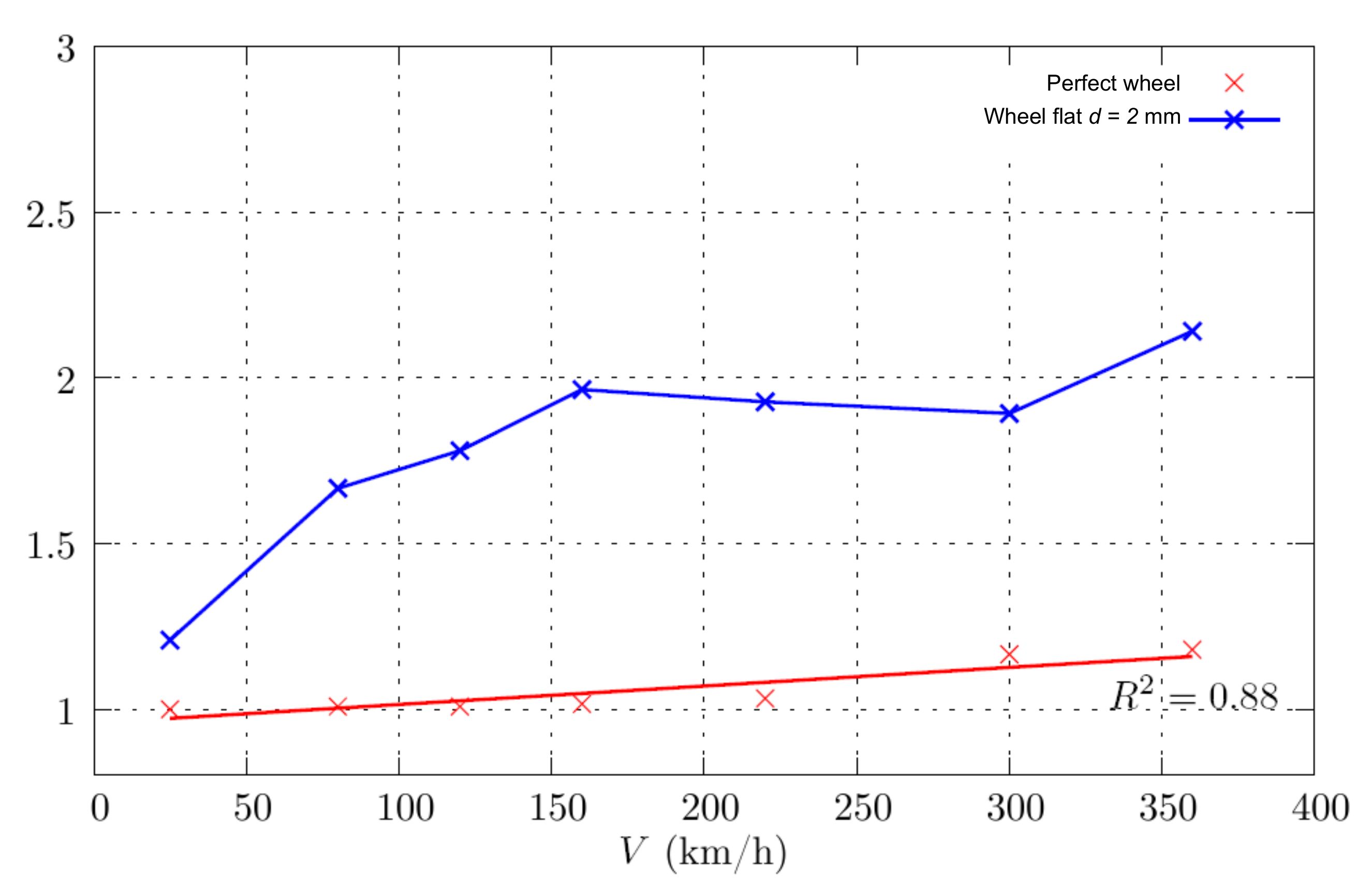
In Figure 9, the evolution of the dynamic amplification factor for the force on the fastening system with the train speed is shown.
From the results, the force on the fastening system was approximately constant for train speeds between 160 and 300 km/h, which shows that the fastening system was absorbing the dynamic impacts. However, at 360 km/h, the force on the fastening system was 44 % higher than that obtained with a perfect wheel.
3.3.2. Slab Track
Figure 10 shows the receptance of the slab track.
From this figure, the most relevant frequencies of the slab track, associated with the vertical deformation, were 167, 589, and 1373 Hz, higher values than those identified for the ballasted track, which revealed that the slab track had greater inertia than the ballasted one. Furthermore, the magnitude of those resonance frequencies was smaller when compared to the values of the ballasted track, confirming the greater rigidity of the slab track.
By analyzing the effects of the wheel flats, the variation of the dynamic load along the slab track due to a wheel flat with a 2 mm depth for the ICE 2 train was included in the study in order to forecast the eventual dynamic behavior of a train at that speed. Vehicle speeds of 25, 160, 220, 300, and 360 km/h are presented in Figure 11.The lower speed of 25 km/h was numerically tested for two main reasons: (i) to highlight the impact not only of the wheel flat, but also of the vehicle speed; (ii) to contribute to the definition of a “safe vehicle speed” in the case of the existence of wheel flats; this “safe speed” was not expected to induce severe dynamic contact loads on the track. The higher speed (360 km/h) was unrealistic for the ICE 2 train, but it was included in the study in order to forecast the eventual dynamic behavior of a train at that speed.
Figure 11 shows that:
- -
- The existence of a wheel flat with a 2 mm depth, for vehicle speeds higher than 25 km/h, led to loss of contact between the wheel and the rail immediately before and after the occurrence of a high-impact load;
- -
- The magnitudes of the impact loads and , for the speed of 300 km/h, were respectively 952.9 kN and 394.7 kN, which were 9.7- and 4.0-times the static load.
From this figure, the dynamic impact load on the track increased with the increase of the vehicle speed; the position of the second impact load from the first impact load increased with the increase of the vehicle speed.
The obtained results showed also that the impact load due to a wheel flat with a 2 mm depth was higher on the slab track than on the ballasted one (see Table 3 and Table 4), because, as is known, the overall track stiffness is higher in the case of a slab track than in the case of a ballasted track, which contributes to the high wheel–rail impact load.
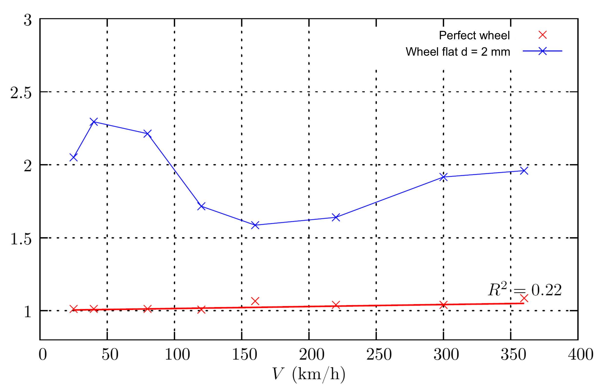
The evolution of the dynamic load amplification factor with the train speed is presented in Figure 12, for the cases of a perfect wheel and a flat wheel flat with a mm depth.
By observing this figure, the dynamic load amplification factor was approximately constant for speeds between 40 and 80 km/h, presenting a slight decrease for a vehicle speed of 120 km/h. These results were similar to those obtained for ballasted tracks by [8,12,40]: the wheel with a flat running at a relatively low speed (between 30 and 40 km/h) may induce higher dynamic loads on the track than those obtained at higher train speeds. From 120 to 360 km/h, the dynamic load amplification factor increased linearly at a high rate.
In this research, the influence of the flat depth on the dynamic response of the slab track was also investigated. In Table 4, the dynamic load obtained for different flat depths is indicated for a vehicle speed of 360 km/h. The peak load for a flat depth of 2 mm was approximately four-times higher than that obtained with a flat depth of mm. The results also showed that on the slab track, there was a loss of contact between the wheel and the rail when the depth of the flats exceeded mm. For the ballasted track, this phenomena only occurred for flat depths greater than 1 mm.
In Figure 13, the dynamic amplification factor for the rail vertical displacement versus the train speed is displayed.
From the Figure, the results showed that a speed of 40 km/h induced a higher maximum track displacement for the wheel flat at a 2 mm depth.
The dynamic amplification factor for the force on the fastening system as a function of the train speed is presented in Figure 14.
From this figure, the maximum force on the fastening system also reached its maximum value for a speed of 40 km/h, which was the speed value that induced the maximum track displacement of the rail. This phenomena was explained by the excitation frequencies.
3.3.3. Ballasted vs. Slab Track
Comparing the dynamic response of the two track systems due to wheel flats, it appeared that for the same traffic conditions: (1) The dynamic force on the slab track was higher than on the ballasted system; (2) The maximum vertical displacement was higher on the ballasted track than on the slab system for vehicle speeds equal to or greater than 120 km/h; (3) The force on the fastening systems was higher on the slab track than on the ballasted one due to the higher slab track stiffness, as shown by the receptance frequency response of the two rail tracks.
In conclusion, the higher overall stiffness and different frequency responses of the slab track, in comparison to the the ballasted track, contributed to the higher wheel–rail impact load. Thus, the effect of the wheel flats is relevant to the vehicle track dynamic behavior, and for that reason, it should not be neglected either for ballasted tracks or slab systems, especially for high-speed railway lines. Additional numerical studies and experimental measurements should be performed in order to correlate the impact forces due to wheel flats with the train speed and track stiffness to propose future regulations on the limit values for wheel flats.
4. Conclusions
This paper presented a numerical analysis for a better understanding of the effects of different geometrical configurations of wheel flats and the train speed on the dynamic behavior of the classical ballasted track and the continuous slab track with punctual fastening of the rail on the sleepers incorporated into the slab. The interaction model for the coupled vehicle track system was defined in 2D, and it comprised the track and the vehicle submodels and a nonlinear contact interaction model between the wheel and the rail.
The numerical simulation presented in this paper showed that (i) the existence of a wheel flat with a 2 mm depth, for vehicle speeds higher than 25 km/h, led to a loss of contact between the wheel and the rail immediately before and after the occurrence of a high-impact load; (ii) the dynamic impact load on the track increased with the increase of the vehicle speed; (iii) the position (distance) of the second impact load (), from the first impact load (), increased with the increase of the vehicle speed; (iv) the magnitude of the impact loads and depended significantly on the train speed and the overall track stiffness; (v) for the same traffic conditions, the dynamic force was higher on the slab track than on the ballasted system, while the the maximum vertical displacement was higher on the ballasted track due to the system’s flexibility.
Funding
This work was financially supported by Base Funding—UIDB/04708/2020—and Programmatic Funding—UIDP/04708/2020 of CONSTRUCT—Instituto de I&D em Estruturas e Construções funded by national funds through the FCT/MCTES (PIDDAC).
Institutional Review Board Statement
Not applicable.
Informed Consent Statement
Not applicable.
Conflicts of Interest
The author declares no conflict of interest.
References
- UIC. Feasibility Study Ballastless Track; UIC Infrastructure Commission-Civil Engineering Support Group: Chicago, IL, USA, 2002. [Google Scholar]
- Zhou, C.; Gao, L.; Xiao, H.; Hou, B. Railway Wheel Flat Recognition and Precise Positioning Method Based on Multisensor Arrays. Appl. Sci. 2020, 10, 1297. [Google Scholar] [CrossRef] [Green Version]
- Shim, J.; Kim, G.; Cho, B.; Koo, J. Application of vibration signal processing methods to detect and diagnose wheel flats in railway vehicles. Appl. Sci. 2021, 11, 2151. [Google Scholar] [CrossRef]
- Mosleh, A.; Montenegro, P.; Alves Costa, P.; Calçada, R. An approach for wheel flat detection of railway train wheels using envelope spectrum analysis. Struct. Infrastruct. Eng. 2020. [Google Scholar] [CrossRef]
- Mosleh, A.; Montenegro, P.A.; Costa, P.A.; Calçada, R. Railway Vehicle Wheel Flat Detection with Multiple Records Using Spectral Kurtosis Analysis. Appl. Sci. 2021, 11, 4002. [Google Scholar] [CrossRef]
- Vale, C.; Bonifácio, C.; Seabra, J.; Calçada, R.; Mazzino, N.; Elisa, M.; Terribile, S.; Anguita, D.; Fumeo, E.; Saborido, C.; et al. Novel Efficient Technologies in Europe for Axle Bearing Condition Monitoring—The MAXBE Project. Transp. Res. Procedia 2016, 14, 635–644. [Google Scholar] [CrossRef] [Green Version]
- Newton, S.G.; Clark, R.A. An Investigation into the Dynamic Effects on the Track of Wheelflats on Railway Vehicles. J. Mech. Eng. Sci. 1979, 21, 287–297. [Google Scholar] [CrossRef]
- Dukkipati, R.V.; Dong, R. Impact Loads due to Wheel Flats and Shells. Veh. Syst. Dyn. 1999, 31, 1–22. [Google Scholar] [CrossRef]
- Johansson, A.; Nielsen, J.C.O. Out-of-round railway wheels: Wheel-rail contact forces and track response derived from field tests and numerical simulations. Proc. Inst. Mech. Eng. Part F J. Rail Rapid Transit 2005, 217, 135–146. [Google Scholar] [CrossRef]
- Wu, T.X.; Thompson, D.J. A Hybrid Model for Wheel/Track Dynamic Interaction and Noise Generation due to Wheel Flats; ISVR Technical Memorandum, No. 859; University of Southampton: Southampton, UK, 2001. [Google Scholar]
- Johansson, A.; Andersson, C. Out-of-round railway wheels—A study of wheel polygonalization thought simulation of three-dimensional wheel–rail interaction and wear. Veh. Syst. Dyn. 2005, 43, 539–559. [Google Scholar] [CrossRef]
- Seco, M.; Sanchez, E.; Vinolas, J. A time domain wheelflat/track FE model. In Proceedings of the Conference on Railway Condition Monitoring, Birmingham, UK, 29–30 November 2006. [Google Scholar]
- Baeza, L.; Roda, A.; Carballeira, J.; Giner, E. Railway train-track dynamics for wheelflats with improved contact models. Nonlinear Dyn. 2006, 45, 385–397. [Google Scholar] [CrossRef]
- Steenbergen, M.J.M.M. The role of the contact geometry in wheel–rail impact due to wheel flats. Veh. Syst. Dyn. 2007, 45, 1097–1116. [Google Scholar] [CrossRef]
- Uzzal, R.U.A.; Ahmed, W.; Rakheja, S. Dynamic analysis of railway vehicle-track interactions due to wheel flat with a pitch-plane vehicle model. J. Mech. Eng. 2008, 39, 86–94. [Google Scholar] [CrossRef] [Green Version]
- Pieringer, A.; Kropp, W.; Nielsen, J.C.O. The influence of contact modeling on simulated wheel/rail interaction due to wheel flats. Wear 2014, 314, 273–281. [Google Scholar] [CrossRef] [Green Version]
- Yang, J.; Thompson, D.J. Time-domain prediction of impact noise from wheel flats based on measured profiles. J. Sound Vib. 2014, 333, 3981–3995. [Google Scholar] [CrossRef]
- Uzzal, R.A.; Ahmed, W.; Bhat, R. Impact analysis due to multiple wheel flats in three-dimensional railway vehicle-track system model and development of a smart wheel set. Proc. Inst. Mech. Eng. Part F J. Rail Rapid Transit 2016, 230. [Google Scholar] [CrossRef]
- Han, L.; Jin, L.; Liu, K. A dynamic simulation of the wheel–rail impact caused by a wheel flat using a 3-D rolling contact model. J. Mod. Transp. 2017, 25, 124–131. [Google Scholar] [CrossRef] [Green Version]
- Lei, X.; Noda, N.A. Analysis of dynamic response of vehicle and track coupling system with random irregularity track vertical profile. J. Sound Vib. 2002, 258, 147–165. [Google Scholar] [CrossRef]
- Sun, Y.Q.; Dhanasekar, M. A dynamic model for the vertical interaction of the rail track and wagon system. Int. J. Solids Struct. 2002, 39, 1337–1359. [Google Scholar] [CrossRef]
- Lua, F.; Kennedy, D.; Williams, F.W.; Lin, J.H. Symplectic analysis of vertical random vibration for coupled vehicle-track systems. J. Sound Vib. 2008, 317, 236–249. [Google Scholar] [CrossRef]
- Rigueiro, C.; Rebelo, C.; Silva, L. Influence of ballast models in the dynamic response of railways viaducts. J. Sound Vib. 2010, 329, 3030–3040. [Google Scholar] [CrossRef]
- Suzuki, T.; Ishida, M.; Abe, K.; Koro, K. Measurement on Dynamic Behaviour of Track Near Rail Joints and Prediction of Track Settlement; Quarterly Report of the Railway Technical Research Institute (RTRI); Railway Technical Research Institute (RTRI): Tokyo, Japan, 2005; Volume 46. [Google Scholar]
- Gomes-Correia, A.; Cunha, J.; Marcelino, J.; Caldeira, L.; Varandas, J.; Dimitrovová, J.Z.; Antão, A.; Silva, M.G. Dynamic analysis of rail track for high speed trains. 2D approach. In Applications of Computational Mechanics in Geotechnical Engineering; Sousa, V., Azevedo, F., Eds.; Taylor and Francis: Abingdon-on-Thames, UK, 2007. [Google Scholar]
- Kuo, C.M.; Huang, C.H. Two approaches of finite-element modeling of ballasted railway track. J. Geotech. Geoenviron. Eng. ASCE 2009, 135, 455–458. [Google Scholar] [CrossRef]
- Paderno, C. Simulation of ballast behavior under traffic and tamping process. In Proceedings of the 9th Swiss Transport Research Conference, Ascona, Switzerland, 9–11 September 2009. [Google Scholar]
- Vale, C.; Calçada, R. Dynamic response of a coupled vehicle-track system to real longitudinal rail profiles. In Proceedings of the Tenth International Conference on Computational Structures Technology (CST 2010), Valencia, Spain, 14–17 September 2010. [Google Scholar]
- Vale, C.; Calcada, R. A Dynamic Vehicle-Track Interaction Model for Predicting the Track Degradation Process. J. Infrastruct. Syst. 2014. [Google Scholar] [CrossRef]
- Ziyaeifar, M. Interaction study of train-bridge-track systems using Maxwell model. Veh. Syst. Dyn. 2005, 43, 771–794. [Google Scholar] [CrossRef]
- Johnson, K.L. Contact Mechanics; Cambridge University Press: Cambridge, UK, 1985. [Google Scholar]
- Wriggers, P.; Zavarise, G. Chapter 6: Computational Contact Mechanics, Encyclopedia of Computational Mechanics. In Solids and Structure; Stein, E., de Bost, R., Hughes, T.J.R., Eds.; John Wiley and Sons: Hoboken, NJ, USA, 2004; Volume 2. [Google Scholar]
- Nash, S.; Sofer, A. Linear and Nonlinear Programming; Edition Industial Engineering Series; McGraw-Hill: New York, NY, USA, 1996. [Google Scholar]
- UIC. Design of New Lines for Speed of 300–350 km/h—State of Art; UIC: Chicago, IL, USA, 2001. [Google Scholar]
- UIC. UIC 719: Earthworks and Track Bed for Railway Lines; UIC: Chicago, IL, USA, 2008. [Google Scholar]
- Nielsen, J.C.O.; Lundén, R.A.R.; Johansson, A.; Vernersson, T. Train-track interaction and mechanisms of irregular wear on wheel and rail surfaces. Veh. Syst. Dyn. 2003, 40, 3–54. [Google Scholar] [CrossRef]
- ERRI. ERRI-D214/RP9- Railway Bridges for Speed > 200 km/h; Final Report; European Rail Research Institute (ERRI): Utrecht, The Netherlands, 2001. [Google Scholar]
- Nielsen, J.C.O.; Igel, A. Vertical Dynamic Interaction between Train and Track—Influence of Wheel and Track Imperfections. J. Sound Vib. 1995, 187, 825–839. [Google Scholar] [CrossRef]
- Oberg, J. Track Deterioration of Ballasted Track—Marginal Cost Model for Railway Vehicles. Ph.D. Thesis, Royal Institutet of Technology Aeronautical and Vehicle Engineering, Stockholm, Sweden, 2006. [Google Scholar]
- Remennikov, A.M.; Kaewunruen, S. A review of loading conditions for railway track structures due to train and track vertical interaction. Struct. Control. Health Monit. 2008, 15, 207–234. [Google Scholar] [CrossRef]
Figure 1.
Track model with continuous modeling of the granular layers.

Figure 2.
Track model of continuous slab systems.

Figure 3.
Quarter bogie model.

Figure 4.
Quarter bogie model: ICE 2 locomotive.

Figure 5.
Receptance of the ballasted track.

Figure 6.
Variation of the dynamic load along the ballasted track due to a wheel flat running at 300 km/h ( mm). (a) Along the track; (b) detail.
Figure 6.
Variation of the dynamic load along the ballasted track due to a wheel flat running at 300 km/h ( mm). (a) Along the track; (b) detail.

Figure 7.
Dynamic amplification factor for the dynamic load: perfect wheel vs. flat wheel ( mm), ballasted track.
Figure 7.
Dynamic amplification factor for the dynamic load: perfect wheel vs. flat wheel ( mm), ballasted track.

Figure 8.
Dynamic amplification factor for the rail vertical displacement: perfect wheel vs. flat wheel ( mm), ballasted track.
Figure 8.
Dynamic amplification factor for the rail vertical displacement: perfect wheel vs. flat wheel ( mm), ballasted track.

Figure 9.
Dynamic amplification factor for the force on the fastening system: perfect wheel vs. flat wheel ( mm), ballasted track.
Figure 9.
Dynamic amplification factor for the force on the fastening system: perfect wheel vs. flat wheel ( mm), ballasted track.

Figure 10.
Receptance of the slab track.

Figure 11.
Variation of the dynamic load along the slab track for various vehicle speeds due to a wheel flat ( mm). (a) V = 25, 160, and 220 km/h; (b) V = 300 and 360 km/h.
Figure 11.
Variation of the dynamic load along the slab track for various vehicle speeds due to a wheel flat ( mm). (a) V = 25, 160, and 220 km/h; (b) V = 300 and 360 km/h.

Figure 12.
Dynamic amplification factor for the dynamic load: perfect wheel vs. flat wheel ( mm), slab track.
Figure 12.
Dynamic amplification factor for the dynamic load: perfect wheel vs. flat wheel ( mm), slab track.

Figure 13.
Dynamic amplification factor for the (rail) vertical displacement: perfect wheel vs. flat wheel ( mm), slab track.
Figure 13.
Dynamic amplification factor for the (rail) vertical displacement: perfect wheel vs. flat wheel ( mm), slab track.

Figure 14.
Dynamic amplification factor for the force on the fastening system: perfect wheel vs. flat wheel ( mm), slab track.
Figure 14.
Dynamic amplification factor for the force on the fastening system: perfect wheel vs. flat wheel ( mm), slab track.


Table 1.
Geometrical and mechanical characteristics of the ballasted track components.
| Component/Type of Element | Parameter |
|---|---|
| rail UIC 60 | GPa; cm |
| (beam | ; cm |
| Euler–Bernoulli) | kg/m |
| pad | kN/mm |
| (spring and dashpot) | kN/m |
| sleeper | m |
| (punctual mass) | kg |
| ballast | L = 2.5 m |
| and sub-ballast | MPa |
| (plane-stress element) | ; m |
| foundation | kN/mm |
| (Winkler foundation) | kN/m |
Table 2.
Geometrical and mechanical characteristics of the slab track components.
| Component/Type of Element | Parameter |
|---|---|
| rail UIC 60 | GPa; cm |
| (beam Euler | ; cm |
| Bernoulli) | kg/m |
| pad | kN/mm |
| (spring and dashpot | kN/mm |
| in parallel) | kN/m |
| embedded sleeper | kg |
| (punctual mass) | m |
| slab | GPa; |
| (plane-stress | kg/m |
| 8-node elements) | m |
| cement treated base | GPa; |
| (plane-stress | m; kg/m |
| 8-node elements) | m |
| foundation | kN/mm |
| (Winkler foundation) | kN/m |
Table 3.
Dynamic load on the ballasted track for different wheel flat depths (V = 360 km/h).
| F | d | d | d | d | d |
|---|---|---|---|---|---|
| (kN) | 0 mm | 0.5 mm | 1.0 mm | 1.5 mm | 2.0 mm |
| Min. | |||||
| Max. |
Min., minimum value; Max., maximum value; d, wheel flat depth.
Table 4.
Dynamic load on the slab track for different wheel flat depths (V = 360 km/h).
| F | d | d | d | d | d |
|---|---|---|---|---|---|
| (kN) | 0 mm | 0.5 mm | 1.0 mm | 1.5 mm | 2.0 mm |
| Min. | |||||
| Max. |
Min., minimum value; Max., maximum value; d, wheel flat depth.
Publisher’s Note: MDPI stays neutral with regard to jurisdictional claims in published maps and institutional affiliations. |
© 2021 by the author. Licensee MDPI, Basel, Switzerland. This article is an open access article distributed under the terms and conditions of the Creative Commons Attribution (CC BY) license (https://creativecommons.org/licenses/by/4.0/).
Share and Cite
MDPI and ACS Style
Vale, C. Wheel Flats in the Dynamic Behavior of Ballasted and Slab Railway Tracks. Appl. Sci. 2021, 11, 7127. https://doi.org/10.3390/app11157127
AMA Style
Vale C. Wheel Flats in the Dynamic Behavior of Ballasted and Slab Railway Tracks. Applied Sciences. 2021; 11(15):7127. https://doi.org/10.3390/app11157127
Chicago/Turabian StyleVale, Cecilia. 2021. "Wheel Flats in the Dynamic Behavior of Ballasted and Slab Railway Tracks" Applied Sciences 11, no. 15: 7127. https://doi.org/10.3390/app11157127
Note that from the first issue of 2016, this journal uses article numbers instead of page numbers. See further details here.