Article

Dynamic Analysis of Ball Screw Feed System with the Effects of Excitation Amplitude and Design Parameters

School of Mechanical Engineering and Automation, Northeastern University, Shenyang 110819, China
*
Author to whom correspondence should be addressed.
Appl. Sci. 2021, 11(15), 7070; https://doi.org/10.3390/app11157070
Submission received: 10 June 2021 / Revised: 14 July 2021 / Accepted: 27 July 2021 / Published: 30 July 2021
(This article belongs to the Topic Dynamical Systems: Theory and Applications)

Abstract

:
In this paper, a nine degree-of-freedom dynamic model of the ball screw feed system considering the contact nonlinearity between balls and raceways is established to analyze the vibration characteristics. The position relationship between raceway centers for the ball screw and bearings is determined by using the homogeneous coordinate transformation, and then the restoring force functions along the axial and lateral directions are derived. The dynamic equations of the feed system are solved by using Newmark method, and the proposed model is verified by the experimental method. Furthermore, the effect of the excitation amplitude on the axial vibration of the feed system is investigated by the frequency-amplitude curve and 3-D frequency spectrum. With the increase of excitation amplitude, the dynamic response of the feed system exits the softening, hardening type nonlinearity and jump phenomenon. Additionally, the effects of the initial contact angle, length of screw shaft and number of loaded balls on the axial vibration of the feed system in the resonance region are discussed. The results show that the dynamic model established in this paper is suitable for improving the machining accuracy and stability of the ball screw feed system.

1. Introduction

The ball screw is a transmission device that converts linear motion into rotary motion or rotary motion into linear motion, and it has the advantages of high position accuracy, load capacity and fatigue life [1,2,3]. The dynamic characteristic of the feed system is the key factor to determine the machining accuracy of the workpiece and stability of the cutting process [4,5], and the nonlinear contact relationship between balls and raceways leads to the complexity and instability of the worktable vibration [6,7]. Therefore, the establishment of a dynamic model of the feed system is of great significance to improve the machining accuracy and stability.
The feed system contains many kinematic joints, and their contact load distribution is an important factor to determine the static behavior and contributes to the dynamic behaviors of the feed system. Assuming that the contact angles do not vary after loading, Mei et al. [8] analyzed the effect of the ball errors on the load distribution of the ball screw. Bertolaso et al. [9] studied the contact load of the ball screw by experimental and numerical methods. Considering the axial and lateral deformations of the screw shaft, Lin et al. [10] investigated the effect of the ball error and screw shaft offset on the load distribution of the ball screw. Zhao et al. [11] and Zhen et al. [12] investigated the effects of the ball dimension errors, axial and radial loads on the contact load and fatigue life of ball screws. Liu et al. [13] established a static model of ball screws to analyze the effect of nut position on the distribution of the contact force, contact angle and torsion angle. Due to the sliding behavior between balls and grooves, the contact angles are greatly different at the contact areas [14,15]. Wei et al. established a numerical model to investigate the lubrication [16], transmission efficiency [17] and wear [18] for a preloaded ball screw system. Chen et al. [19] established the 5-DOF static model of a double-nut ball screw to investigate the contact stiffness characteristics.
The dynamic characteristic of the feed system is significant for the machining accuracy of the workpiece. Nguyen et al. [20] investigated the relationship between preload, worktable displacement and screw-nut natural frequency for the feed system. Deng et al. [21] improved the vibration behaviors of the whole machine tool based on the joint stiffness configuration. Zhang et al. [22] investigated the effect of the screw shaft pre-stretching on the natural frequency for the feed system. When the feed system is at high acceleration, the contact stiffness of the kinematic joints may change. By using the lumped parameter method, Zhang et al. [23] investigated the influence of acceleration on the vibration characteristics for the feed system. Vicente et al. [24] established a high-frequency dynamic model of the feed system by simulating screw shaft as a continuous subsystem. Zhang et al. [25] established an equivalent dynamic model of a high-speed feed system to analyze the effect of feed rates on the natural frequency. Considering the contact nonlinearity between ball and raceways, Gu et al. [26] studied the dynamic behaviors of a single-nut ball screw feed system. Xu et al. [27] proposed a lumped dynamic model by deriving the restoring force function of the axial deformation for the feed system.
The vibrations of the feed system along different directions are coupled with each other. By simulating the screw shaft as a Timoshenko beam, Okwudire et al. [28,29] established a screw-nut interface stiffness model of ball screws considering the axial, torsional and lateral deformations. Using the finite element method, Hung et al. [30] analyzed the vibration behaviors and machining accuracy for the vertical milling system. Zhang et al. [31] established a hybrid dynamic model of a ball screw spindle system to analyze the rigid-flexible coupling vibration. Wang et al. [32] studied the coupling vibration characteristics of the feed system considering the contact nonlinearity of kinematic joints. Liu et al. [33] developed a five degree-of-freedom dynamic model of a worktable system considering the displacement coupling and assembly errors. To suppress the worktable vibration of the machine tool, Varanasi et al. [34] developed a dynamic model of a ball screw considering the distributed inertia of the screw shaft to effectively control the structural vibration. Gordon and Erkorkmaz [35] investigated the active vibration damping and positioning control by using the pole-placement technique of the feed system. Wang et al. [36] developed a hollow screw shaft structure with multiple tuned mass dampers to suppress the lateral vibration of the ball screw.
In the past, the dynamic model of the ball screw feed system has been established successfully. However, the influence of design parameters on the axial vibration of the feed system in the resonance region is rarely discussed. Considering that the vibration characteristics of the feed system are mainly affected by screw nut, screw shaft and ball bearing, a novel nine degree-of-freedom dynamic model of the feed system is established in this paper by deriving the restoring force functions of the screw nut and ball bearing along the x, y and z directions. The effects of the excitation amplitude, initial contact angle, length of screw shaft and number of loaded balls on the dynamic response of the feed system are discussed. In addition, the dynamic behaviors of the feed system at the resonance points are analyzed by the time history, spectrum, phase diagram and Poincaré section.

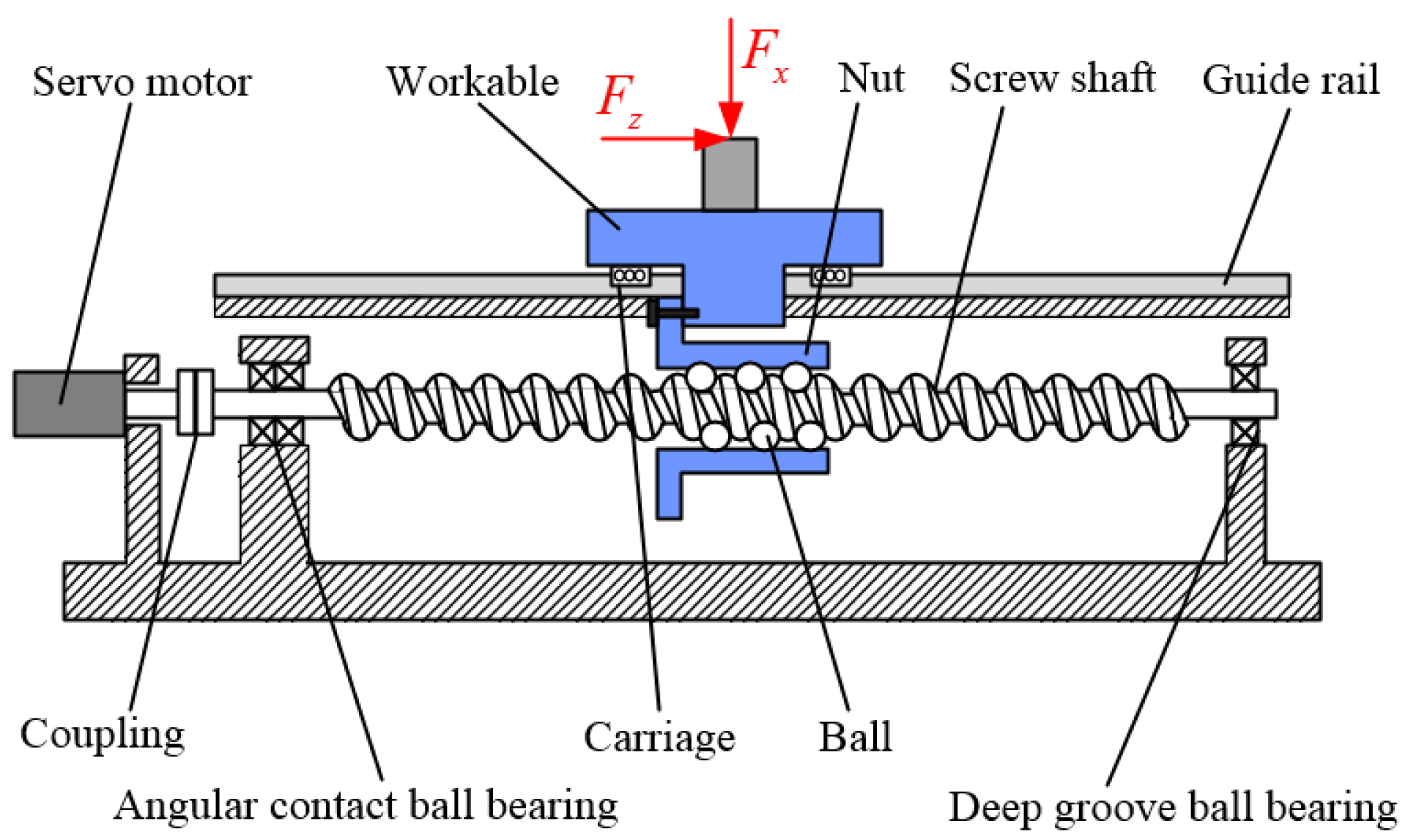
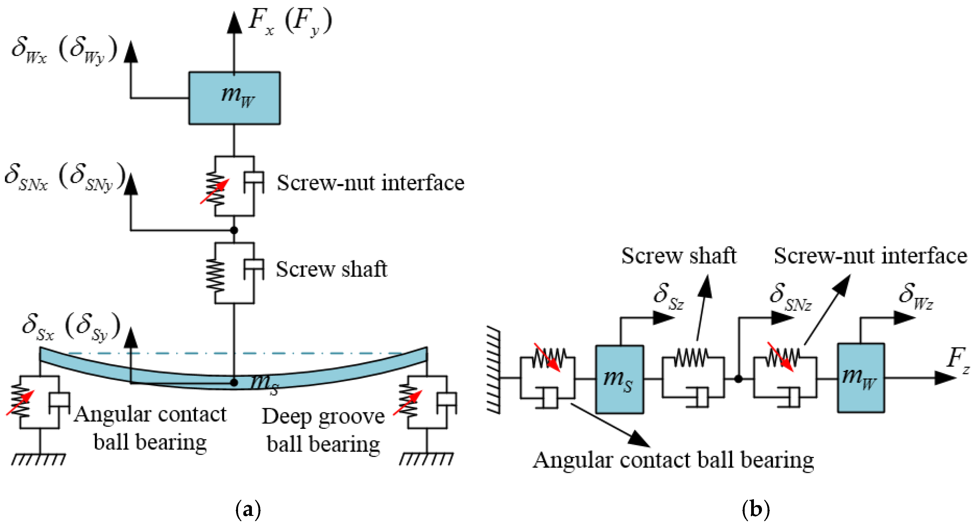
2. Dynamic Model of the Feed System

The ball screw feed system model is composed of a worktable, a nut, a screw shaft, balls, two linear guides, two angular contact ball bearings and a deep groove ball bearing, as shown in Figure 1. The global coordinate system CS 0 ( x , y , z ) is located at the geometric center of the nut chassis, and the worktable (nut) is assumed to be located at the middle position of the screw shaft. Under the action of cutting force, the worktable may move along the x, y and z directions due to the deformations of the screw nut, screw shaft and bearing. In this paper, we simplify the feed system as a spring mass model to analyze the influences of the excitation amplitude and design parameters on the axial vibration of the feed system.

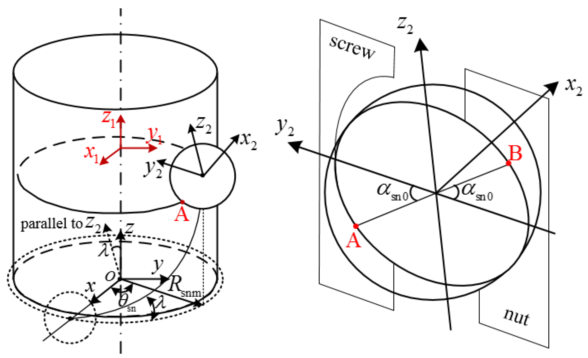
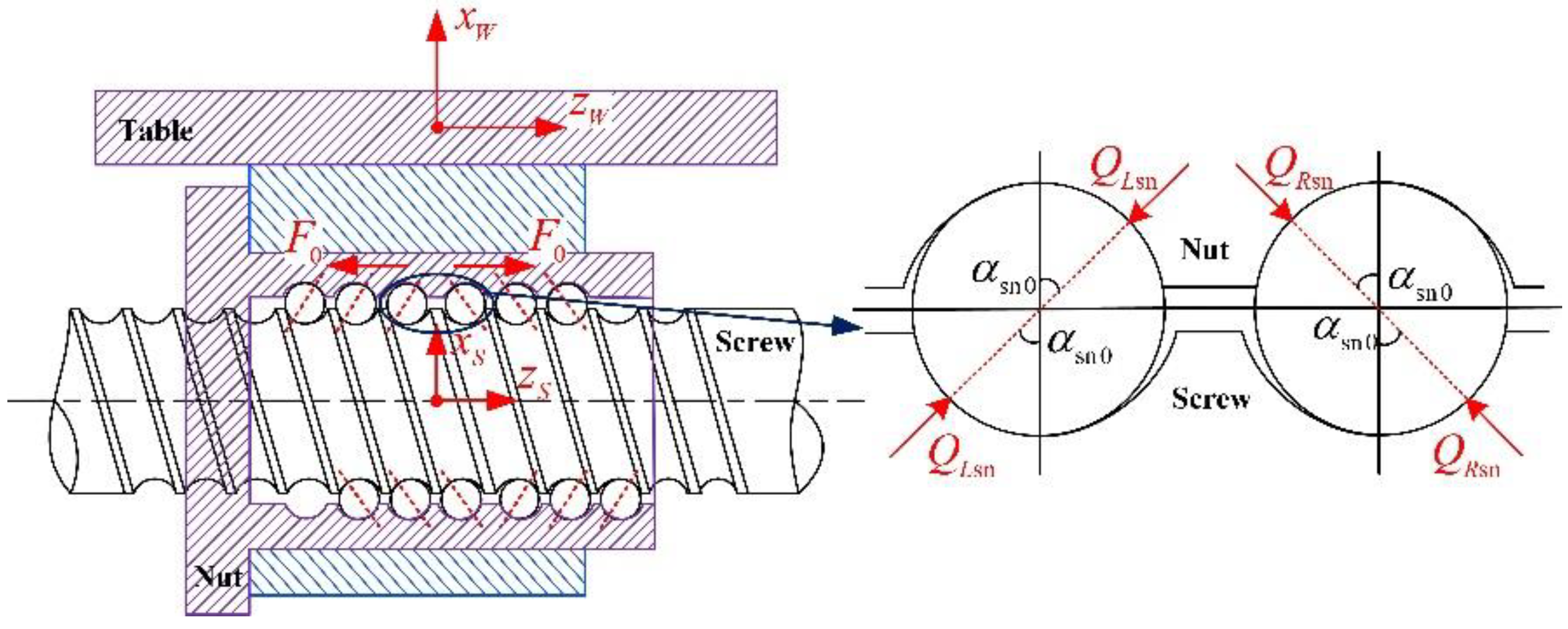
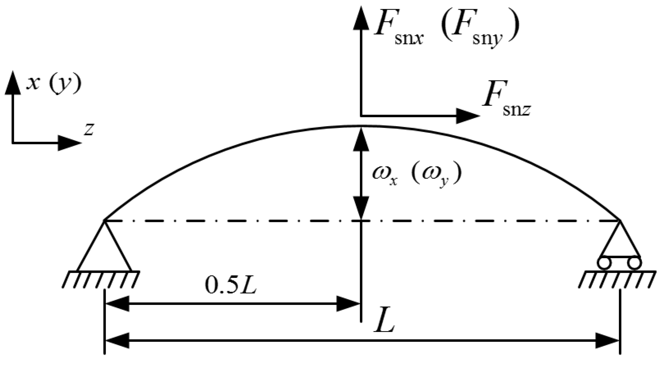
2.1. Calculation of Restoring Force for Ball Screw

To deduce the restoring force function at the screw-nut interface, the position relationship of the raceway centers of the screw and nut needs to be described, and then the transformation relationship between the different coordinate systems should be established. As shown in Figure 2, the global coordinate system CS 0 ( x , y , z ) is fixed at the geometric center of the nut chassis; the coordinate system CS 1 ( x 1 , y 1 , z 1 ) is located at the screw shaft centerline corresponding to the ith ball center, and its axes are parallel to the CS 0 axes; the coordinate system CS 2 ( x 2 , y 2 , z 2 ) is located at the ith ball center, and its y 2 axis is perpendicular to the screw shaft centerline; the coordinate systems CS W ( x W , y W , z W ) and CS S ( x S , y S , z S ) are located at the geometric centers of the worktable and the screw shaft for the screw-nut interface, respectively, and their three axes are parallel to the CS 0 axes. The homogeneous coordinate transformation matrix T 1 2 from CS 1 to CS 2 can be expressed as:
T 1 2 = Trans ( R snm cos θ sn i , R snm sin θ sn i , 0 ) · Rot z ( θ sn i + π 2 ) · Rot y ( λ )
where R snm is the pitch radius; θ sn i is the ith ball azimuth angle; λ is the pitch angle, given as:
λ = tan 1 ( L p 2 π R snm )
where L p is the lead of ball screw.

2.1.1. Restoring Force for the Screw-Nut Left Section

The structure of a single nut ball screw with preload applied by variable lead is shown in Figure 3. Considering that the ball contact force direction for the screw-nut left and right sections is different, this leads to the different restoring force function for the screw-nut left and right sections. Therefore, it is necessary to describe the position of the raceway centers in CS 0 , respectively. The position vectors ( R L s , R L n ) of the raceway centers corresponding to the ith ball for the screw-nut left section in CS 2 can be given by:
R L s = [ 0 ( R s R b ) cos α sn 0 ( R s R b ) sin α sn 0 1 ] T
R L n = [ 0 ( R n R b ) cos α sn 0 ( R n R b ) sin α sn 0 1 ] T
where R s and R n are the raceway radius of the screw and nut; R b is the ball radius; α sn 0 is the initial contact angle.
Combining Equations (1), (3) and (4), the coordinates of the raceway centers corresponding to the ith ball for the screw-nut left section in CS S and CS W can be expressed as:
[ X L s i S Y L s i S Z L s i S 1 ] T = Trans ( 0 , 0 , L L b i ) · T 1 2 · R L s
[ X L n i W Y L n i W Z L n i W 1 ] T = Trans ( H W , 0 , L L b i ) · T 1 2 · R L n
where H W is the distance along the x-axis direction between the CS W ’s origin and the nut centerline; L L b i is the displacement of the ith ball center for the screw-nut left section along the z-axis direction in CS S ( CS W ), given by:
L L b i = L D 2 + ( i 1 ) Δ L
where L D is axial distance between the first ball and last ball; Δ L is the distance along the z-axis direction between adjacent balls.
Considering that the center position of the nut raceway changes with the worktable posture variation, this affects the functions of the screw-nut restoring force. We assumed that at the geometric center of the worktable exists three translational displacements ( δ W x , δ W y , δ W z ) along x W , y W and z W axes under the action of excitation force. According to the homogeneous coordinate transformation, the coordinates of the nut raceway center in CS 0 are:
[ x L n i W y L n i W z L n i W 1 ] = Trans ( H W , 0 , L O W ) · Trans ( δ W x , δ W y , δ W z ) [ X L n i W Y L n i W Z L n i W 1 ]
where L O W is the axial distance between CS 0 and CS S ( CS W ).
Because the screw shaft at the screw-nut interface is short, we assumed that this section of screw shaft is rigid. Similarly, the geometric center of screw shaft at the screw-nut interface exits three translational displacements ( δ S N x , δ S N y , δ S N z ) along x S , y S and z S directions caused by the axial and bending deformations of screw shaft. The coordinates of the screw raceway center in CS 0 are:
[ x L s i S y L s i S z L s i S 1 ] = Trans ( 0 , 0 , L O W ) · Trans ( δ S N x , δ S N y , δ S N z ) · [ X L s i S Y L s i S Z L s i S 1 ]
Combining Equations (8) and (9), the radial distance σ L sn i of raceway centers for the screw-nut left section can be expressed as:
σ L sn i = ( x L s i S x L n i W ) cos θ sn i + ( y L s i S y L n i W ) sin θ sn i
With the increase of excitation amplitudes, the ball may lose contact with the raceway, which affects the nonlinear contact characteristics of the feed system. To judge whether each ball is loaded or not, if δ L sn i 0 , then the ith ball is not loaded, and the contact force is Q L sn i = 0 . If δ L sn i > 0, then the ith ball is loaded, and the contact force Q L sn i can be obtained by using Hertz contact theory, given by:
Q L sn i = { ( δ L sn i + δ sn 0 C s i + C n i ) 2 / 3   δ L sn i + δ sn 0 > 0 0 δ L sn i + δ sn 0 0
where C s i and C n i are the Hertz contact constant of the screw and nut; δ sn 0 is contact deformation under the preload; δ L sn i is contact deformation of ith ball for the screw-nut left section, which is composed of the ball-screw contact deformation δ L s i and the ball-nut contact deformation δ L n i , given by:
δ L sn i = δ L s i + δ L n i = σ L sn i 2 + ( z L n i W z L s i S ) 2 A 0
where A 0 is the initial distance of raceway centers, given by:
A 0 = R s + R n 2 R b
According to the position relationship of raceway centers in CS 0 , the contact angle α L sn i for the screw-nut left section can be expressed as:
α L sn i = cos 1 ( σ L sn i A 0 + δ L sn i + δ sn 0 )
In order to calculate the restoring force for the screw-nut left section, the ball contact force should be transformed into equivalent force. According to the homogeneous coordinates transformation, the restoring forces of ball screws along the x, y and z directions can be expressed by:
F L sn x = i = 1 N b Q L sn i ( cos θ sn i cos α L sn i + sin α L sn i sin θ sn i sin λ )
F L sn y = i = 1 N b Q L sn i ( cos α L sn i sin θ sn i sin α L sn i cos θ sn i sin λ )
F L sn z = i = 1 N b Q L sn i sin θ sn i cos λ
where N b is the number of loaded balls.

2.1.2. Restoring Force for the Screw-Nut Right Section

Similar to the restoring force calculation for the screw-nut left section method, the position vectors of the raceway centers corresponding to the ith ball for the screw-nut right section in CS2 can be given as:
R R s = [ 0 ( R s R b ) cos α 0 ( R s R b ) sin α sn 0 1 ] T
R R n = [ 0 ( R n R b ) cos α 0 ( R n R b ) sin α sn 0 1 ] T
The coordinates of the raceway centers for the screw-nut right section in CS S and CS W can be expressed as:
[ X R s i S Y R s i S Z R s i S 1 ] T = Trans ( 0 , 0 , L R b i ) · T 1 2 · R R s
[ X R n i W Y R n i W Z R n i W 1 ] T = Trans ( H W , 0 , L R b i ) · T 1 2 · R R n
where L R b i is the displacement of the ith ball center for the screw-nut right section along the z-axis direction in CS S ( CS W ), which can be expressed as:
L R b i = L D 2 ( N b i ) Δ L
By the homogeneous coordinate transformation, the coordinates of the raceway centers for the screw-nut right section in CS 0 can be expressed as:
[ x R s i S y R s i S z R s i S 1 ] = Trans ( 0 , 0 , L O W ) · Trans ( δ S N x , δ S N y , δ S N z ) · [ X R s i S Y R s i S Z R s i S 1 ]
[ x R n i W y R n i W z R n i W 1 ] = Trans ( H W , 0 , L O W ) · Trans ( δ W x , δ W y , δ W z ) · [ X R n i W Y R n i W Z R n i W 1 ]
According to the position relationship of raceway centers, the radial distance σ R sn i of the raceway centers for the screw-nut right section can be expressed as:
σ R sn i = ( x R s i S x R n i W ) cos θ sn i + ( y R s i S y R n i W ) sin θ sn i
Considering that the ball may lose contact with the raceway, the contact force Q R sn i can be obtained by using the Hertz contact theory, given by:
Q R sn i = { ( σ R sn i 2 + ( z R n i W z R s i S ) 2 A 0 + δ sn 0 C s i + C n i ) 2 / 3 δ R sn i + δ sn 0 > 0 0 δ R sn i + δ sn 0 0
where δ R sn i is ith ball contact deformation for the screw-nut right section.
According to the position relationship of raceway centers, the contact angle α R sn i for the screw-nut right section can be expressed as:
α R sn i = cos 1 ( σ R sn i A 0 + δ R sn i + δ sn 0 )
By transforming the ball contact force into an equivalent force along the x, y and z directions, the restoring forces for the screw-nut right section can be expressed as:
F R sn x = i = 1 N b Q R sn i ( cos α R sn i cos θ sn i sin α R sn i sin θ sn i sin λ )
F R sn y = i = 1 N b Q R sn i ( cos α R sn i sin θ sn i + sin α R sn i cos θ sn i sin λ )
F R sn z = i = 1 N b Q R sn i sin θ sn i cos λ

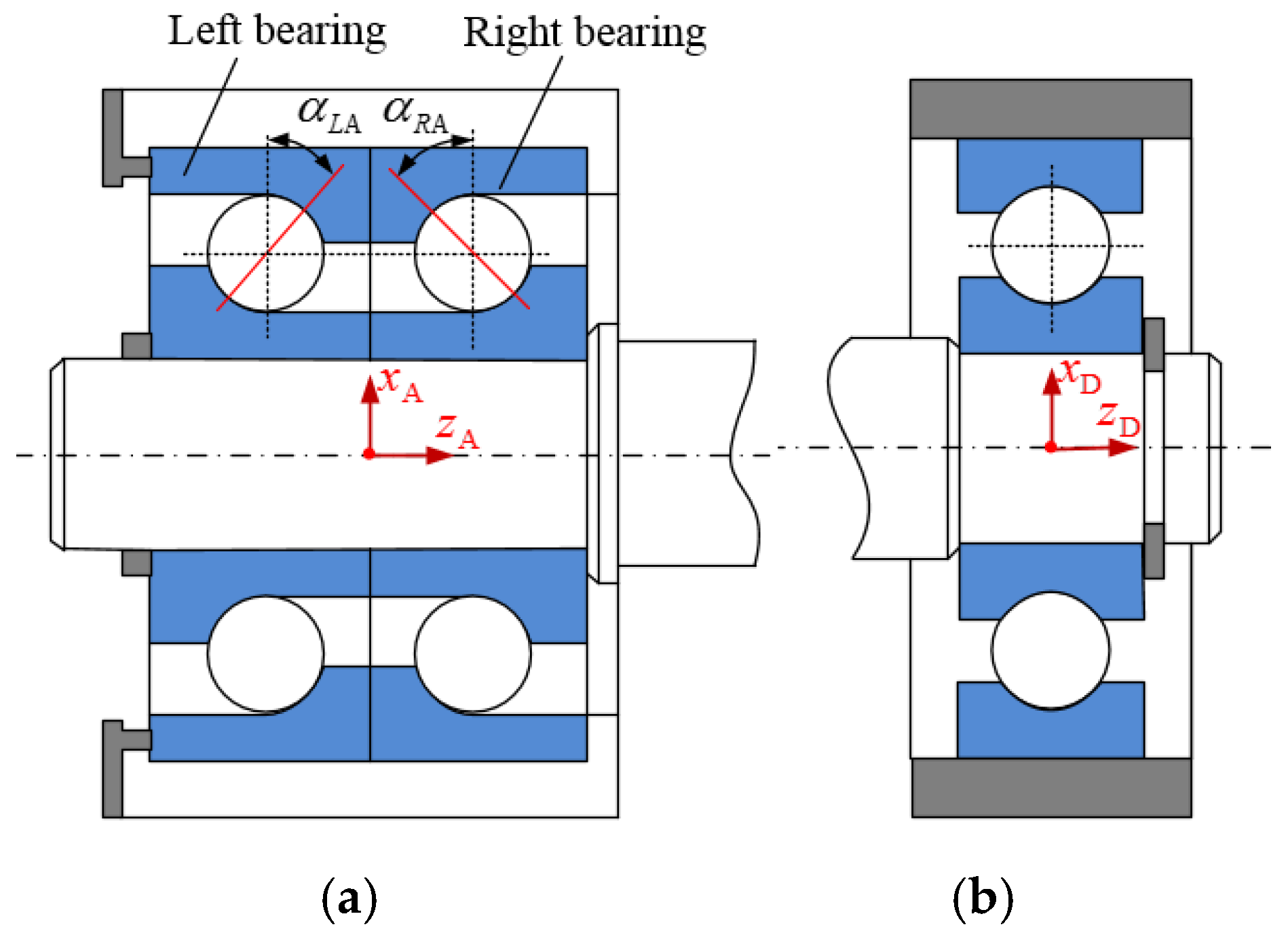
2.2. Calculation of Restoring Force of Bearings

To calculate the restoring force of bearings, the position relationship of the raceway centers should be determined. The coordinate systems CS Ab ( x A , y A , z A ) and CS Db ( x D , y D , z D ) are established at the geometric centers of the two angular contact ball bearings and a deep groove ball bearing, respectively, and their axes are parallel to those of CS 0 , as shown in Figure 4.

2.2.1. Restoring Force of Angular Contact Ball Bearing

The coordinates of the inner and outer raceway centers for the left angular contact ball bearing in CS Ab are:
[ x L i j A y L i j A z L i j A 1 ] = Trans ( R Am cos θ b j + δ S x , R Am sin θ b j + δ S y , L L A + δ S z ) · Rot z ( θ b j + π 2 ) · [ 0 ( R i R bb ) cos α b 0 ( R i R bb ) sin α b 0 1 ]
[ x L o j A y L o j A z L o j A 1 ] = Trans ( R Am cos θ b j , R Am sin θ b j , L L A ) · Rot z ( θ b j + π 2 ) · [ 0 ( R o R bb ) cos α b 0 ( R o R bb ) sin α b 0 1 ]
where δ S x , δ S y and δ S z are the displacement of the screw shaft along the x, y and z directions; R Am is the pitch radius; R i and R o are the inner and outer raceway radius; R bb is the ball radius; α b 0 and θ b j are the initial contact angle and jth ball azimuth angle; L L A is the axial distance between the ball center and the CS Ab ’s origin for the left angular contact ball bearing, respectively.
The coordinates of the raceway centers for the right angular contact ball bearing in CS Ab are:
[ x R i j A y R i j A z R i j A 1 ] = Trans ( R Am cos θ b j + δ S x , R Am sin θ b j + δ S y , L R A + δ S z ) · Rot z ( θ b j + π 2 ) · [ 0 ( R i R bb ) cos α b 0 ( R i R bb ) sin α b 0 1 ]
[ x R o j A y R o j A z R o j A 1 ] = Trans ( R Am cos θ b j , R Am sin θ b j , L R A ) · Rot z ( θ b j + π 2 ) · [ 0 ( R o R bb ) cos α b 0 ( R o R bb ) sin α b 0 1 ]
where L R A is the axial distance between the ball center and the CS Ab ’s origin for the right angular contact ball bearing, respectively.
According to Equations (31)–(34), the radial distances ( σ L A j , σ R A j ) of the raceway centers for the left and right angular contact ball bearings are expressed by:
σ L A j = ( x L i j A x L o j A ) cos θ b j + ( y L i j A y L o j A ) sin θ b j
σ R A j = ( x R i j A x R o j A ) cos θ b j + ( y R i j A y R o j A ) sin θ b j
According to the position relationship of raceway centers in CS Ab , the contact force Q L A j and contact angle α L A j for the left angular contact ball bearing can be obtained by using the Hertz contact theory, given as:
Q L A j = { ( σ L A j 2 + ( z L i j A z L o j A ) 2 B 0 + δ A 0 C Ai j + C Ao j ) 2 / 3   δ L A j + δ A 0 > 0 0 δ L A j + δ A 0 0
α L A j = cos 1 ( σ L A j B 0 + δ L A j + δ A 0 )
where δ A 0 is contact deformation under the preload; δ L A i is contact deformation between the jth ball and the raceways for the left angular contact ball bearing; B 0 is the initial distance of the raceway centers; C Ai j and C Ao j are the Hertz contact constant of the inner and outer rings.
The contact force and contact angle for the right angular contact ball bearing can be expressed as:
Q R A j = { ( σ R A j 2 + ( z R i j A z R o j A ) 2 B 0 + δ A 0 C Ai j + C A o j ) 2 / 3   δ R A j + δ A 0 > 0 0 δ R A j + δ A 0 0
α R A j = cos 1 ( σ R A j B 0 + δ R A j + δ A 0 )
where δ R A j is contact deformation between the jth ball and the raceways for the right angular contact ball bearing.
The restoring forces along the x, y and z directions for the left angular contact ball bearing can be expressed as:
F L A x = j = 1 N bb Q L A j cos θ b j cos α L A j
F L A y = j = 1 N bb Q L A j sin θ b j cos α L A j
F L A z = j = 1 N bb Q L A j sin α L A j
The restoring forces along the x, y and z directions for the right angular contact ball bearing can be expressed as:
F R A x = j = 1 N bb Q R A j cos θ b j cos α R A j
F R A y = j = 1 N bb Q R A j sin θ b j cos α R A j
F R Az = j = 1 N bb Q R A j sin α R A j

2.2.2. Restoring Force of Deep Groove Ball Bearing

According to the homogeneous coordinate transformation, the coordinates of the inner and outer raceway centers for the deep groove ball bearing in CS Db are expressed by:
[ x i j D y i j D z i j D 1 ] = Trans ( R Dm cos θ b j + δ S x , R Dm sin θ b j + δ S y , δ S z ) · Rot z ( θ b j + π 2 ) · [ 0 ( R i R bb ) ( R i R bb ) 1 ]
[ x o i D y o i D z o i D 1 ] = Trans ( R Dm cos θ b j , R Dm sin θ b j , 0 ) · Rot z ( θ b j + π 2 ) · [ 0 ( R o R bb ) ( R o R bb ) 1 ]
where R Dm is the pitch radius of deep groove ball bearing.
Combining Equations (47) and (48), the radial distance σ D j of raceway centers can be expressed as:
σ D j = ( x i j D x o j D ) cos θ b j + ( y i j D y o j D ) sin θ b j
Considering that the ball may lose contact with the raceway and according to the Hertz contact theory, the contact force Q D j of the deep groove ball bearing can be expressed as:
Q D j = { ( σ D j B 0 C Di j + C Do j ) 2 / 3 σ D j B 0 > 0 0 σ D j B 0 0
The restoring forces along the x and y directions for the deep groove ball bearing can be expressed as:
F D x = j = 1 N bb Q D j cos θ b j
F D y = j = 1 N bb Q D j sin θ b j

2.3. Stiffness of Screw Shaft

Under the influence of the screw-nut restoring force, the bending deformation of the screw shaft for the worktable locating at middle position is shown in Figure 5. The bending deformations of the screw shaft for the screw-nut interface can be expressed by:
{ ω x = ( F L sn x + F R sn x ) ( 2 L ) 6 E I ( 4 L 2 2 L 2 ( 2 L ) 2 ) ω y = ( F L sn y + F R sn y ) ( 2 L ) 6 E I ( 4 L 2 2 L 2 ( 2 L ) 2 )
where E is the Young’s modulus; I is the product of inertia; L is the length of screw shaft.
The axial deformation of screw shaft at the screw-nut interface is:
ω z = ( F L sn z + F R sn z ) L 2 E A s
Assuming that the worktable is located at the middle position of screw shaft, the screw shaft stiffness can be obtained according to the force-displacement relationship of the Euler Bernoulli beam, given by:
{ k x = 48 E I L 3 k y = 48 E I L 3 k z = 2 E A s L

2.4. Dynamic Equations of Ball Screw System

The vibration characteristics of the feed system are affected by three harmonic forces F x sin ( ω t ) , F y sin ( ω t ) and F z sin ( ω t ) . In order to investigate the vibration characteristics of the feed system, the dynamic model is simplified as a nine degrees-of-freedom mass-spring-damping model, as shown in Figure 6. The dynamic equations can be written as follows:
{ m W δ ¨ W x + c x ( δ ˙ W x δ ˙ S N x ) + F sn x = F x sin ( ω t ) k S x ( δ S N x δ S x ) + c x ( δ ˙ S N x δ ˙ S x ) = F sn x + c x ( δ ˙ W x δ ˙ S N x ) m S δ ¨ S x + 2 c x δ ˙ S x + F A x + F D x = c x ( δ ˙ S N x δ ˙ S x ) + k S x ( δ S N x δ S x ) m W δ ¨ W y + c y ( δ ˙ W y δ ˙ S N y ) + F sn y = F y sin ( ω t ) k S y ( δ S N y δ S y ) + c y ( δ ˙ S N y δ ˙ S y ) = F sn y + c y ( δ ˙ W y δ ˙ S N y ) m S δ ¨ S y + 2 c y δ ˙ S y + F A y + F D y = c y ( δ ˙ S N y δ ˙ S y ) + k S y ( δ S N y δ S y ) m W δ ¨ W z + c z ( δ ˙ W z δ ˙ S N z ) + F sn z = F z sin ( ω t ) k S z ( δ S N z δ S z ) + c z ( δ ˙ S N z δ ˙ S z ) = F sn z + c z ( δ ˙ W z δ ˙ S N z ) m S δ ¨ S z + c z δ ˙ S z + F A z = c z ( δ ˙ S N z δ ˙ S z ) + k S z ( δ S N z δ S z )
where δ W x , δ W y and δ W z are the displacement of worktable along the x, y and z directions; δ S N x , δ S N y and δ S N z are the displacement along the x, y and z directions caused by the bending deformation of screw shaft; δ S x , δ S y and δ S z are the displacement of the screw shaft along the x, y and z directions; m W and m S are the mass of the worktable and screw shaft, respectively; k S x , k S y and k S z are the stiffness of screw shaft along the x, y and z directions; F sn and F A are the restoring force functions of the screw-nut interface and angular contact ball bearing, respectively, which are given by F sn = F L sn + F L sn , F A = F L A + F R A ; c x , c y and c z are the damping constants of the feed system, respectively, their damping ratio is calculated by the half power bandwidth method. In this paper, the damping ratios along the x, y and z directions are assumed to be ξ x = ξ y = 0.0434 , ξ z = 0.0483 , respectively [32].

3. Results and Discussion

According to the above analysis, the restoring force of the screw nut and bearings are a time-varying piecewise nonlinear function due to the contact behaviors between the ball and raceway, which leads to the nonlinear vibration behaviors of the feed system. In this paper, the THK SBN4016 type of ball screws, NTN 7206B type of angular contact ball bearing and NSK 6206Z type of deep groove ball bearing are selected to carry out numerical simulation, and their main parameters are shown in Table 1 and Table 2.

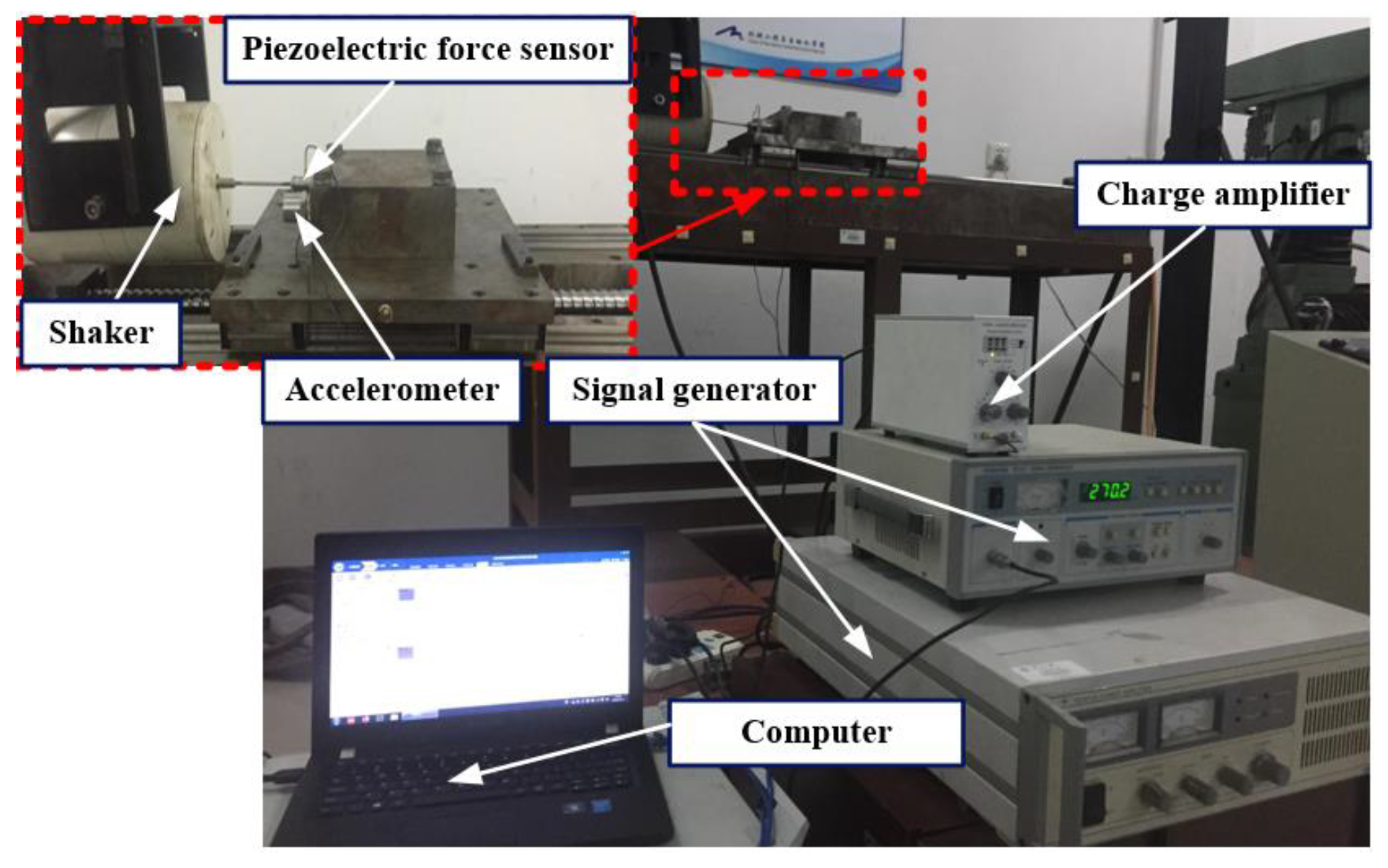
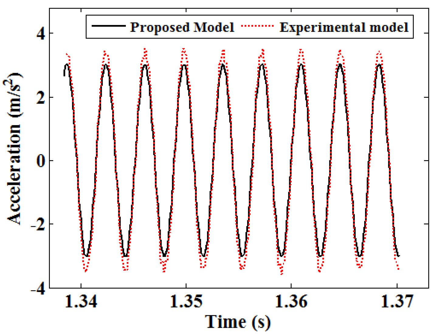
3.1. Experimental Verification

To verify the accuracy of the proposed dynamic model, the experimental model of the feed system was established, as shown in Figure 7. The harmonic exciting force along the z-axis direction is generated by using a modal shaker (JZK-50); a piezoelectric force sensor (Sinocera CL-YD-331A) and acceleration sensor (Sinocera CA-YD-189) are used to measure the excitation force and acceleration of the worktable along the z-axis direction (screw shaft direction). The excitation amplitude and frequency acting on the worktable can be adjusted by the signal generator (Sinocera YE1311). When the excitation amplitude and frequency are fixed at 30 N and 270 Hz, the comparison of acceleration between theoretical and experimental results is shown in Figure 8. It can be seen that the experimental result is slightly larger than the proposed model result, which may be caused by the frame deformation, but the error is within the acceptable range.

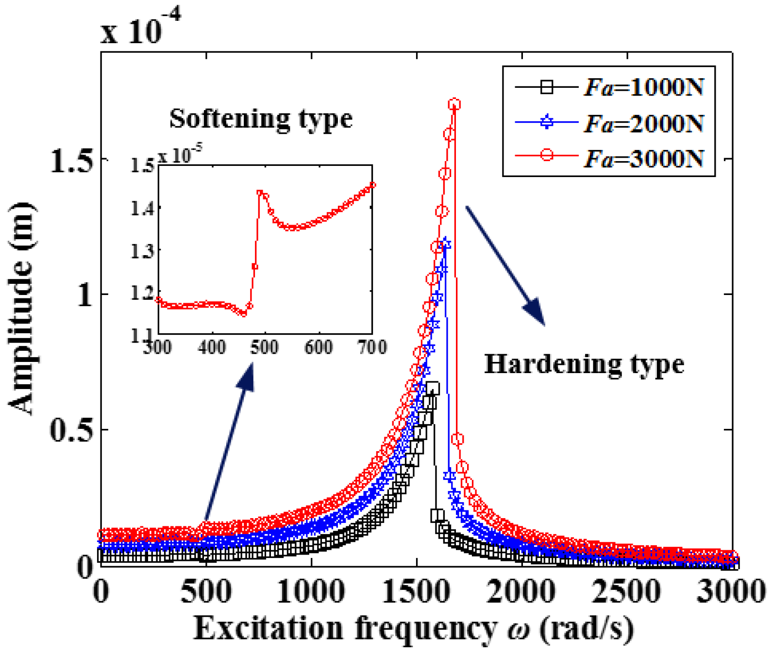
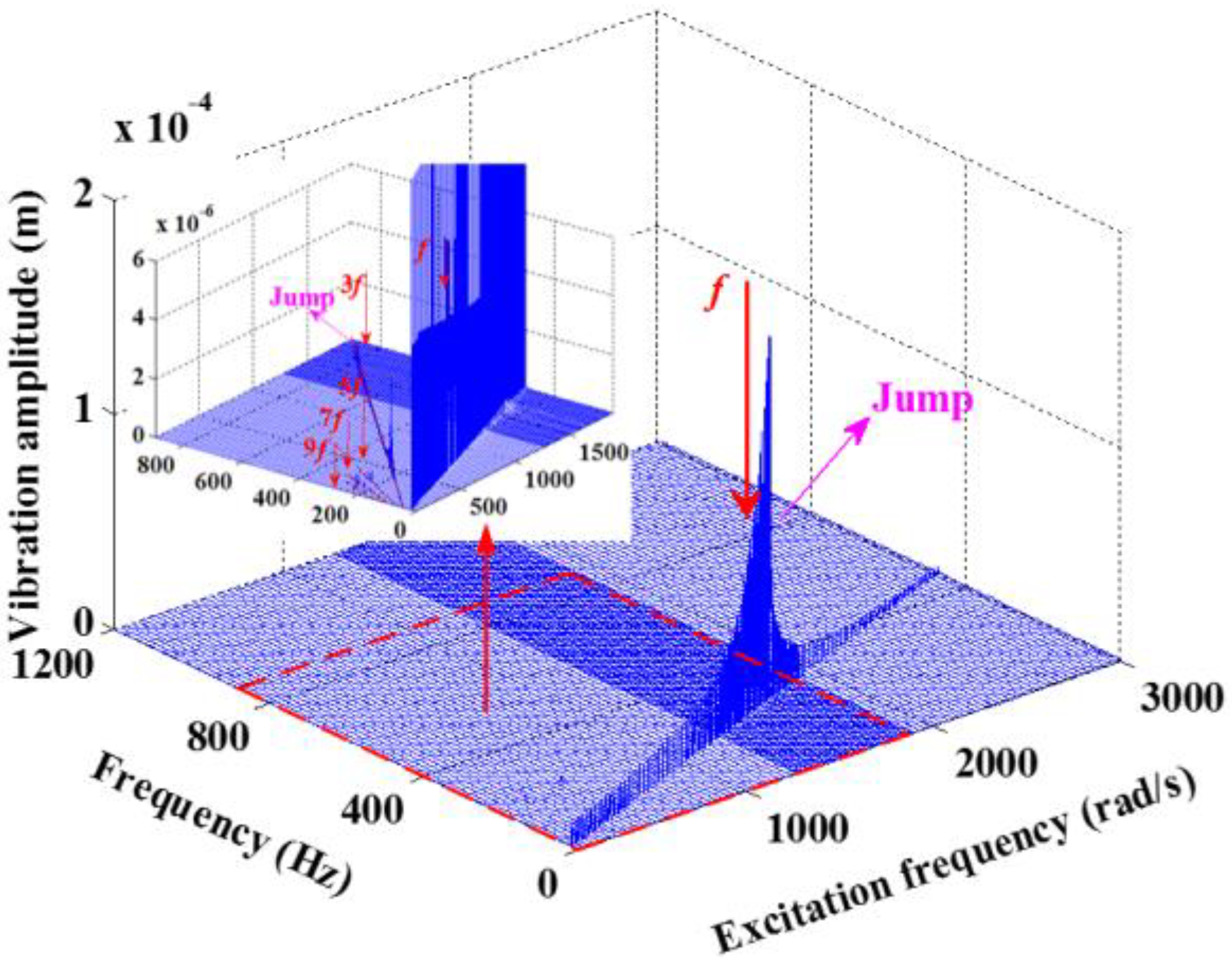
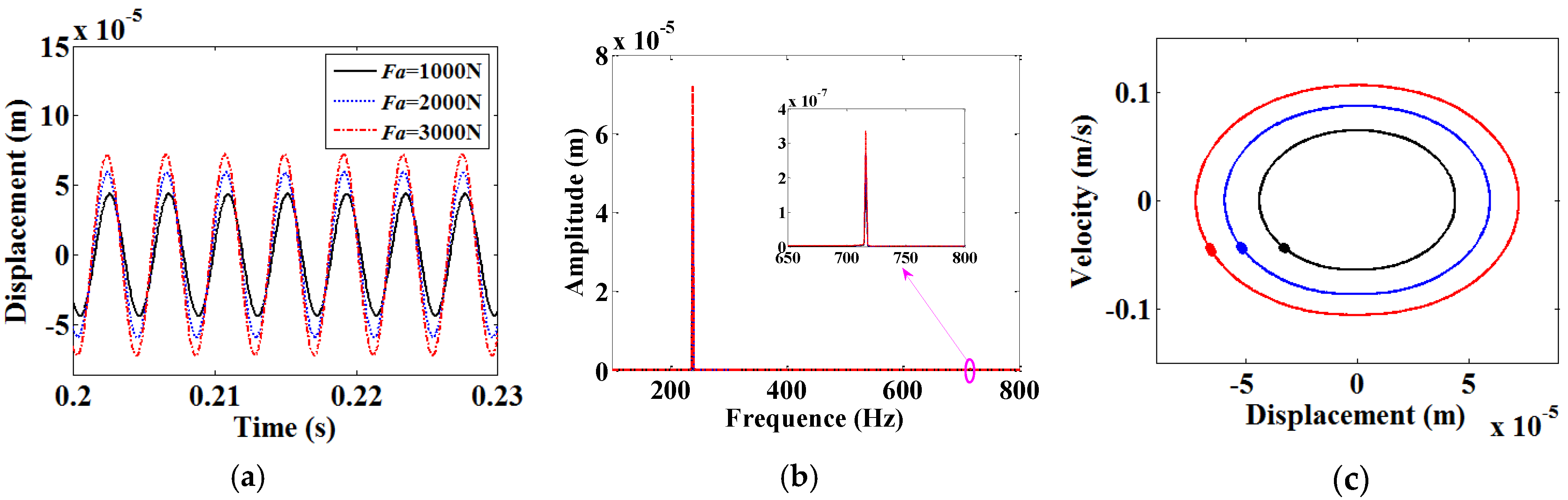
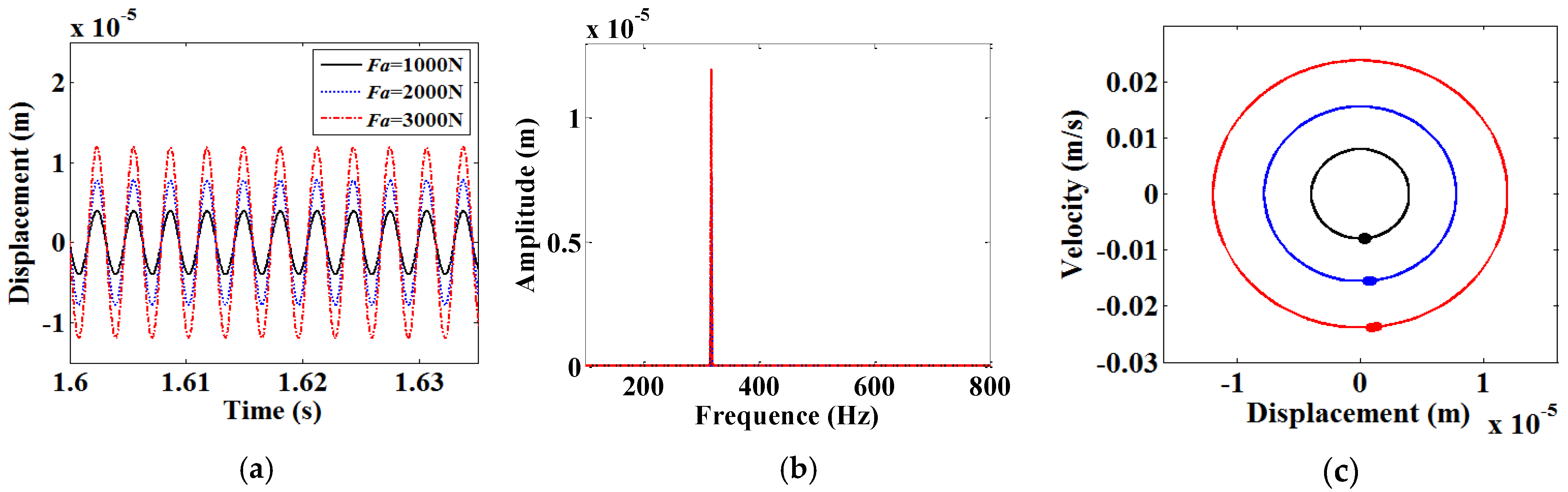
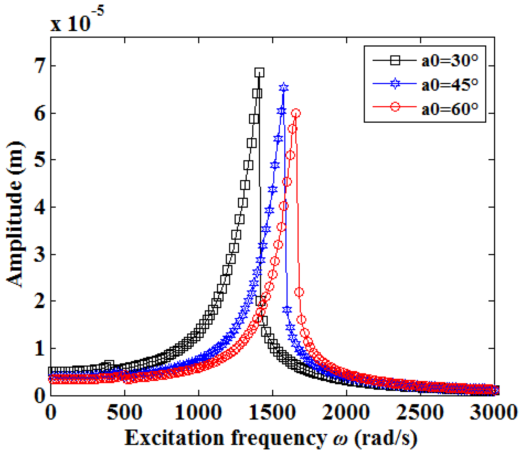
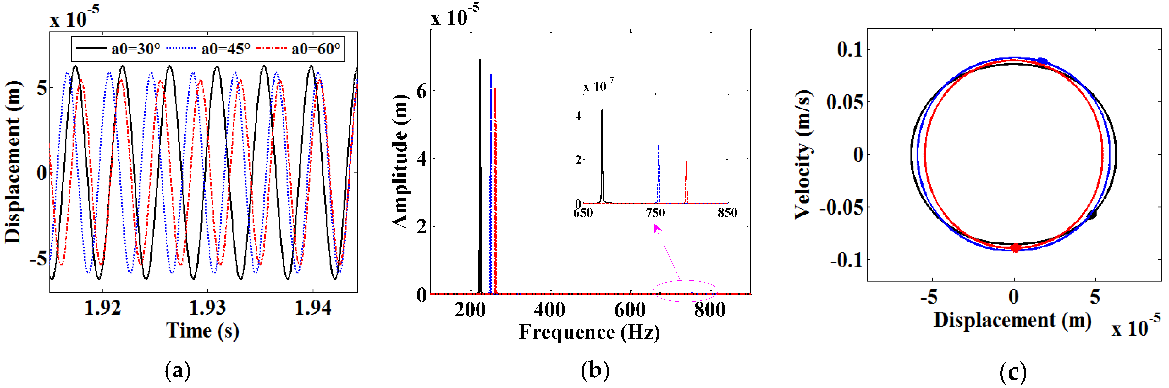
3.2. Effects of Axial Excitation Amplitude on Axial Vibration of the Feed System

It is widely known that the axial vibration of the worktable is the key factor for the machining accuracy and stability of the feed system. For axial excitation amplitudes Fa = 1000 N, 2000 N and 3000 N, the amplitude-frequency curves of the axial vibration of worktable with the excitation amplitude variation are shown in Figure 9. The amplitude-frequency curves appear as softening type nonlinearity around the excitation frequency ω = 500 rad/s. With the further increase of the excitation frequency, the vibration amplitude increases obviously, and the hardening type nonlinearity and jump phenomenon appear after the resonance frequency. In addition, the main resonance frequency moves to the high frequency region and the region width of main resonance increases with the increase of excitation amplitude.
The 3-D frequency spectrum of the worktable vibration along the z direction for Fa= 3000 N is shown in Figure 10, and it can be observed that the different frequency components (3f, 5f et al.) appear in the low excitation frequency region. With the excitation frequency increasing, the amplitudes of frequency components f and 3f increase and the jump phenomenon appears near the excitation frequency ω = 1580 rad/s. To further analyze the nonlinear characteristics of the feed system, the time histories, spectrums, phase diagrams and Poincaré sections are investigated for Fa = 1000 N, 2000 N and 3000 N, as shown in Figure 11, Figure 12 and Figure 13. The vibration waves present periodicity; the frequency component 3f appears at ω = 500 rad/s and 1500 rad/s and disappears with the excitation frequency increasing. In addition, the phase diagrams and Poincaré sections at ω = 500 rad/s, 1500 rad/s and 2000 rad/s are a closed circle and single point, and these illustrate that the vibration responses of the feed system are periodic-1 motions.

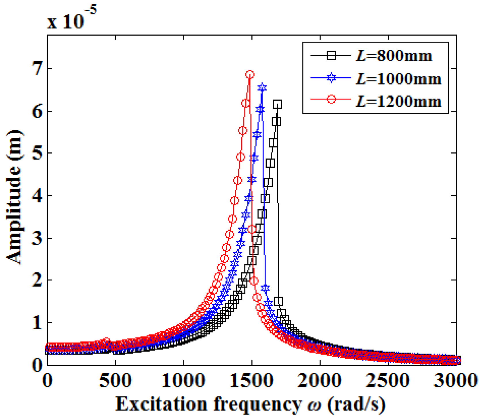
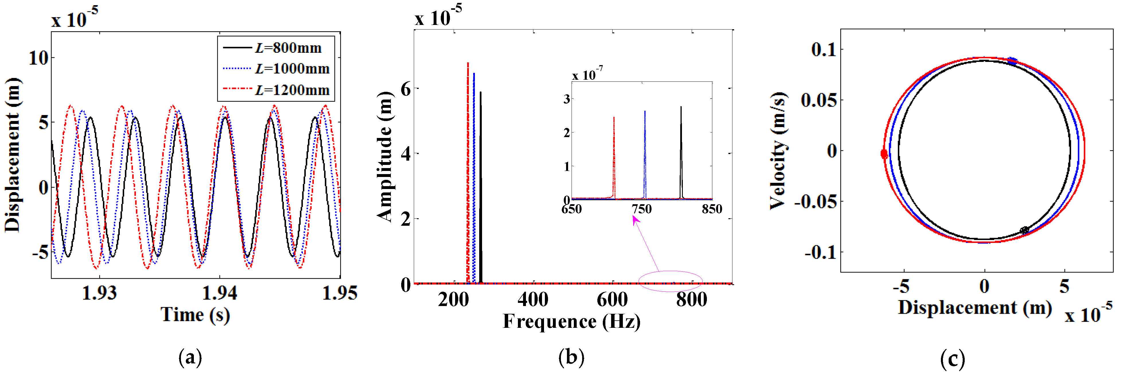
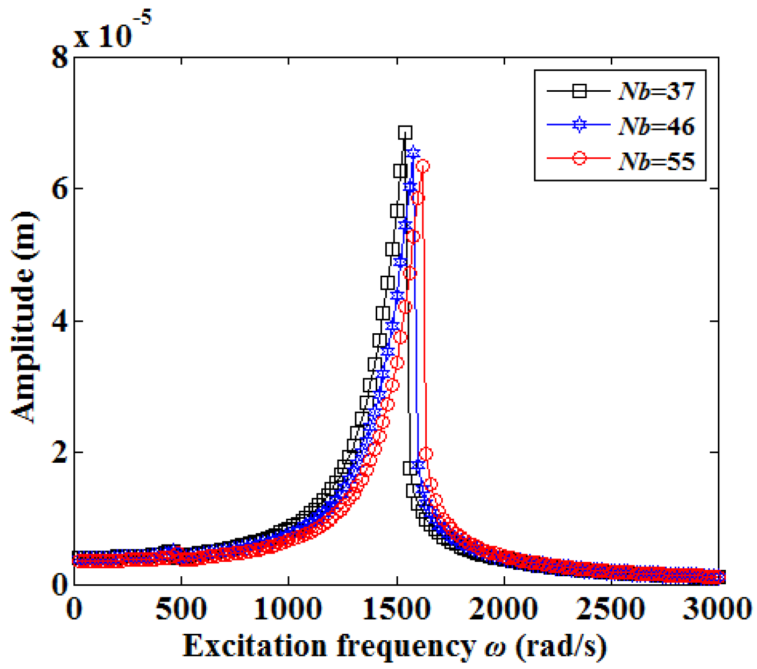
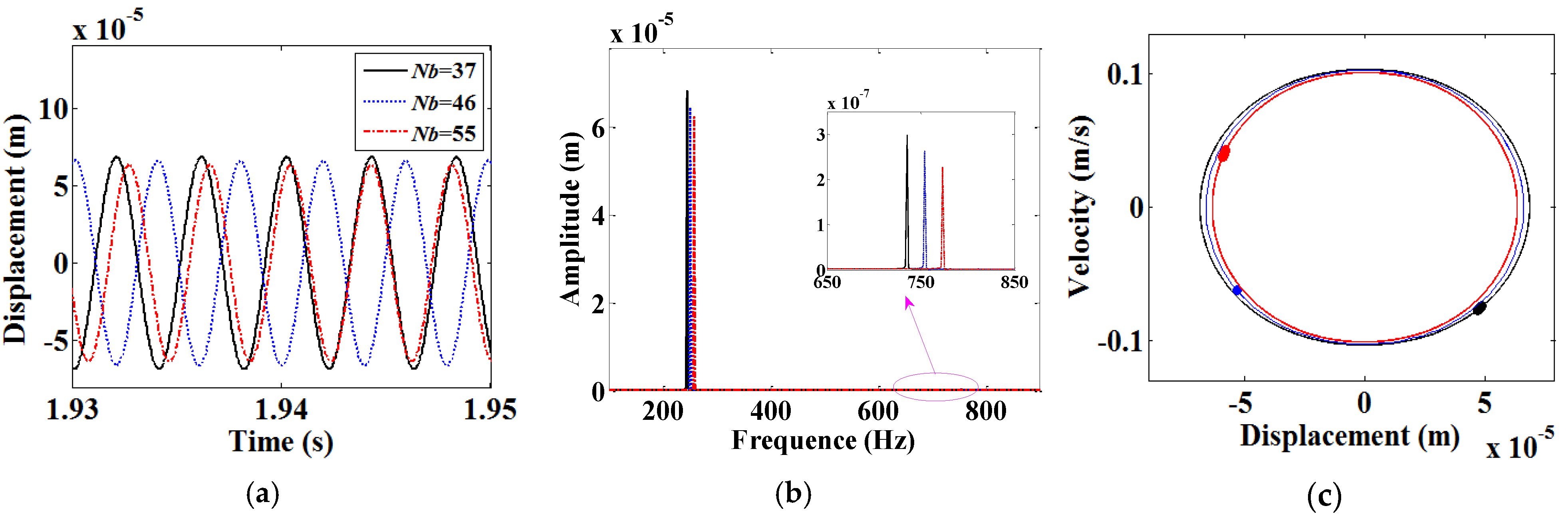
3.3. Effects of Design Parameters on Axial Vibration of the Feed System

The initial contact angle, length of screw shaft and number of loaded balls are the main parameters in the design of the ball screw. According to Equations (17), (30) and (55), the restoring force of the ball screws is a function of these parameters. Obviously, the vibration characteristics of the feed system are influenced by these parameters.
When the axial excitation amplitude is fixed at 1000 N, the amplitude-frequency curves of the worktable vibration with the initial contact angle variation (α0 = 30°, 45°, 60°) are shown are Figure 14. It can be seen that these curves almost coincide in the low and high frequency regions, and the vibration amplitude of the worktable decreases slightly and the main resonance frequency moves to the high frequency region with the initial contact angle increasing. This may be that the initial contact angle increasing makes the increase of axial internal force at the screw-nut interface, which leads to the increase of natural frequency for the feed system. To analyze the influence of the initial contact angle on the nonlinear vibration at the resonance point, the time histories, spectrum, phase diagrams and Poincaré sections are investigated, as shown in Figure 15. With the initial contact angle variation, the Phase diagrams and Poincaré sections are a circle and a single point, respectively, and this shows that the vibration responses with the initial contact angle variation are periodic-1 motions.
With the length of screw shaft variation, the amplitude-frequency curves of the worktable vibration for Fa = 1000 N are shown in Figure 16. The variation tendency of vibration amplitude in the resonance region is opposite to that with the variation of initial contact angle, and the stiffness of the screw shaft at the middle position decreases with the increase of the length of screw shaft, leading to the main resonance frequency of vibration response moving to the low frequency region, and the axial displacement of the worktable increases. The time history, spectrum, phase diagram and Poincaré section are investigated with the length of screw shaft variation, as shown in Figure 17, and the excitation frequency at resonance points increases equivalently with the increase of the length of screw shaft. The difference of the adjacent frequencies is about 20 rad/s; the Phase diagrams and Poincaré sections are a circle and a single point, respectively, and this shows that the vibration responses with the length of screw shaft variation are periodic-1 motions.
With the increase of the number of loaded balls, the amplitude-frequency curves of the worktable vibration for Fa = 1000 N are shown in Figure 18. Similar to the amplitude-frequency curves with the initial contact angle variation, the vibration amplitude of the worktable decreases and the resonance frequency moves to the high frequency region with the increase of the number of loaded balls. As shown in the Figure 19, the frequency components f and 3f appear in the spectrum, and the phase diagrams and Poincaré sections are a circle and a single point, respectively; this illustrates that the vibration responses with the number of loaded balls variation are periodic-1 motions. From the analysis above, the initial contact angle and the number of loaded balls have the same effects on the vibration behaviors of the feed system, but opposite to that of the length of the screw shaft.

4. Conclusions

In this study, a nine degree-of-freedom dynamic model of the feed system is established by deriving the stiffness of the screw shaft and restoring the force functions of the screw nut and bearings. The influence of the excitation amplitude and design parameters on the axial vibration are analyzed. In addition, the effects of the initial contact angle, length of screw shaft and number of loaded balls on the dynamic responses are discussed, and the main conclusions may be summarized as follows:
(1) The nonlinear contact between balls and raceways for the ball screw and bearing is the main factor leading to the nonlinear vibration of the feed system. With the excitation amplitude increasing, the axial vibration of the feed system exits the softening, hardening type nonlinearity and jump phenomenon in the amplitude-frequency curves.
(2) The length of the screw shaft is the main parameter affecting the axial vibration characteristics of the feed system. With the increase of the length of screw shaft, the axial stiffness of the feed system is decreased, resulting in the vibration amplitude increasing and the main resonance frequency moving to the low frequency region.
(3) With the increase of the initial contact angle and number of loaded balls, the axial stiffness increases and the axial vibration nonlinearity decreases for the feed system. Therefore, increasing the initial contact angle and number of loaded balls will improve the stability.
From the analysis above, the axial vibration of the feed system is affected by the screw-nut, screw shaft and bearing, and has strong nonlinearity behavior in the resonance region. Future work will aim to study the influence of excitation amplitude and assembly error on the coupling vibration of the feed system.

Author Contributions

Conceptualization, C.L. and C.Z.; methodology, C.L.; validation, C.L. and Z.L.; formal analysis, C.L. and S.W.; writing, C.L.; supervision, C.Z. All authors have read and agreed to the published version of the manuscript.

Funding

This research was supported by National Natural Science Foundation of China (Grant No. 51775094).

Institutional Review Board Statement

Not applicable.

Informed Consent Statement

Not applicable.

Data Availability Statement

Not applicable.

Conflicts of Interest

The authors declare that there are no competing interests.

References

  1. Huang, S.J.; Wang, S.S. Mechatronics and control of a long-range nanometer positioning servomechanism. Mechatronics 2009, 19, 14–28. [Google Scholar] [CrossRef]
  2. Zhou, C.G.; Feng, H.T.; Chen, Z.T.; Ou, Y. Correlation between preload and no-load drag torque of ball screws. Int. J. Mach. Tools Manuf. 2016, 102, 35–40. [Google Scholar] [CrossRef]
  3. Fukada, S.; Fang, B.; Shigeno, A. Experimental analysis and simulation of nonlinear microscopic behavior of ball screw mechanism for ultra-precision positioning. Precis. Eng. 2011, 35, 650–668. [Google Scholar] [CrossRef]
  4. Li, B.; Luo, B.; Mao, X.Y.; Cai, H.; Peng, F.Y.; Liu, H.Q. A new approach to identifying the dynamic behavior of CNC machine tools with respect to different worktable feed speeds. Int. J. Mach. Tools Manuf. 2012, 72, 73–84. [Google Scholar] [CrossRef]
  5. Mi, L.; Yin, G.F.; Sun, M.N.; Wang, X.H. Effects of preloads on joints on dynamic stiffness of a whole machine tool structure. J. Mech. Sci. Technol. 2012, 26, 495–508. [Google Scholar] [CrossRef]
  6. Zou, C.; Zhang, H.; Lu, D.; Zhang, J.; Zhao, W. Effect of the screw-nut joint stiffness on the position-dependent dynamics of a vertical ball screw feed system without counterweight. Proc. Inst. Mech. Eng. Part C J. Mech. Eng. Sci. 2017, 232, 2599–2609. [Google Scholar] [CrossRef]
  7. Gu, J.; Zhang, Y.; Liu, H. Influences of wear on dynamic characteristics of angular contact ball bearings. Meccanica 2019, 54, 945–965. [Google Scholar] [CrossRef]
  8. Mei, X.; Tsutsumi, M.; Tao, T.; Sun, N. Study on the load distribution of ball screws with errors. Mech. Mach. Theory 2003, 38, 1257–1269. [Google Scholar] [CrossRef]
  9. Bertolaso, R.; Cheikh, M.; Barranger, Y.; Dupré, J.C.; Germaneau, A.; Doumalin, P. Experimental and numerical study of the load distribution in a ball-screw system. J. Mech. Sci. Technol. 2014, 28, 1411–1420. [Google Scholar] [CrossRef]
  10. Lin, B.; Okwudire, C.E.; Wou, J.S. Low order static load distribution model for ball screw mechanisms including effects of lateral deformation and geometric errors. ASME J. Mech. Des. 2017, 140, 022301. [Google Scholar] [CrossRef]
  11. Zhen, N.; An, Q. Analysis of stress and fatigue life of ball screw with considering the dimension errors of balls. Int. J. Mech. Sci. 2018, 137, 68–76. [Google Scholar] [CrossRef]
  12. Zhao, J.J.; Lin, M.X.; Song, X.C.; Guo, Q.Z. Investigation of load distribution and deformations for ball screws with the effects of turning torque and geometric errors. Mech. Mach. Theory 2019, 141, 95–116. [Google Scholar] [CrossRef]
  13. Liu, C.; Zhao, C.Y.; Meng, X.L.; Wen, B.C. Static load distribution analysis of ball screws with nut position variation. Mech. Mach. Theory 2020, 151, 103893. [Google Scholar] [CrossRef]
  14. Lin, M.C.; Velinsky, S.A.; Ravani, B. Design of the ball screw mechanism for optimal efficiency. ASME J. Mech. Des. 1994, 116, 856–861. [Google Scholar] [CrossRef]
  15. Lin, M.C.; Ravani, B.; Velinsky, S.A. Kinematics of the ball screw mechanism. ASME J. Mech. Des. 1994, 116, 849–855. [Google Scholar] [CrossRef]
  16. Wei, C.C.; Lin, J.F.; Horng, J.H. Analysis of a ball screw with a preload and lubrication. Tribol. Int. 2009, 42, 1816–1831. [Google Scholar] [CrossRef]
  17. Wei, C.C.; Lai, R.S. Kinematical analyses and transmission efficiency of a preloaded ball screw operating at high rotational speeds. Mech. Mach. Theory 2011, 46, 80–898. [Google Scholar] [CrossRef]
  18. Wei, C.C.; Liou, W.L.; Lai, R.S. Wear analysis of the offset type preloaded ball-screw operating at high speed. Wear 2012, 292–293, 111–123. [Google Scholar] [CrossRef]
  19. Chen, Y.J.; Tang, W. Dynamic contact stiffness analysis of a double-nut ball screw based on a quasi-static method. Mech. Mach. Theory 2014, 73, 76–90. [Google Scholar] [CrossRef]
  20. Nguyen, T.L.; Ro, S.K.; Park, J.K. Study of ball screw system preload monitoring during operation based on the motor current and screw-nut vibration. Mech. Syst. Signal Proc. 2019, 131, 18–32. [Google Scholar] [CrossRef]
  21. Deng, C.Y.; Yin, G.F.; Fang, H.; Meng, Z.Y. Dynamic characteristics optimization for a whole vertical machining center based on the configuration of joint stiffness. Int. J. Adv. Manuf. Technol. 2015, 76, 1225–1242. [Google Scholar] [CrossRef]
  22. Zhang, W.; Zhang, X.; Zhang, J.; Zhao, W. Analysis of lead screw pre-stretching influences on the natural frequency of ball screw feed system. Precis. Eng. 2019, 57, 30–44. [Google Scholar] [CrossRef]
  23. Zhang, J.; Zhang, H.; Du, C.; Zhao, W. Research on the dynamics of ball screw feed system with high acceleration. Int. J. Mach. Tools Manuf. 2016, 111, 9–16. [Google Scholar] [CrossRef]
  24. Vicente, D.A.; Hecker, R.L.; Villegas, F.J.; Flores, G.M. Modeling and vibration mode analysis of a ball screw drive. Int. J. adv. Manuf. Technol. 2012, 58, 257–266. [Google Scholar] [CrossRef]
  25. Zhang, H.; Zhang, J.; Liu, H.; Liang, T.; Zhao, W. Dynamic modeling and analysis of the high-speed ball screw feed system. Pro. Instit. Mech. Eng. Part B-J. Eng. Manuf. 2014, 229, 870–877. [Google Scholar] [CrossRef]
  26. Gu, J.; Zhang, Y. Dynamic analysis of a ball screw feed system with time-varying and piecewise-nonlinear stiffness. Proc. Inst. Mech. Eng. Part C-J. Mech. Eng. Sci. 2019, 233, 6503–6518. [Google Scholar] [CrossRef]
  27. Xu, M.T.; Cai, B.; Li, C.Y.; Zhang, H.Z.; Liu, Z.D.; He, D.; Zhang, Y.M. Dynamic characteristics and reliability analysis of ball screw feed system on a lathe. Mech. Mach. Theory 2020, 150, 103890. [Google Scholar] [CrossRef]
  28. Okwudire, C.E.; Altintas, Y. Hybrid modeling of ball screw drives with coupled axial, torsional, and lateral dynamics. ASME J. Mech. Des. 2009, 131, 071002. [Google Scholar] [CrossRef]
  29. Okwudire, C.E. Improved screw-nut interface model for high-performance ball screw drives. ASME J. Mech. Des. 2011, 133, 041009. [Google Scholar] [CrossRef]
  30. Hung, J.P.; Lai, Y.L.; Lin, C.Y.; Lo, T.L. Modeling the machining stability of a vertical milling machine under the influence of the preloaded linear guide. Int. J. Mach. Tools Manuf. 2011, 51, 731–739. [Google Scholar] [CrossRef]
  31. Zhang, L.; Wang, T.; Wang, G.; Tian, S. Hybrid dynamic modeling and analysis of a ball-screw-drive spindle system. J. Mech. Sci. Technol. 2017, 31, 4611–4618. [Google Scholar] [CrossRef]
  32. Wang, W.; Zhou, Y.; Wang, H.; Li, C.Y.; Zhang, Y.M. Vibration analysis of a coupled feed system with nonlinear kinematic joints. Mech. Mach. Theory 2019, 134, 562–581. [Google Scholar] [CrossRef]
  33. Liu, C.; Zhao, C.Y.; Wen, B.C. Investigation on coupled vibration of machine tool table system with position deviations. Int. J. Adv. Manuf. Technol. 2021, 114, 2321–2337. [Google Scholar] [CrossRef]
  34. Varanasi, K.K.; Nayfeh, S.A. The Dynamics of lead-screw drives: Low-order modeling and experiments. ASME J. Dyn. Syst. Meas. Control 2004, 126, 388–396. [Google Scholar] [CrossRef]
  35. Gordon, D.J.; Erkorkmaz, K. Accurate control of ball screw drives using pole-placement vibration damping and a novel trajectory prefilter. Precis. Eng. 2013, 37, 308–322. [Google Scholar] [CrossRef]
  36. Wang, M.; Zan, T.; Gao, X.; Li, S. Suppression of the time-varying vibration of ball screws induced from the continuous movement of the nut using multiple tuned mass dampers. Int. J. Mach. Tools Manuf. 2016, 107, 41–49. [Google Scholar] [CrossRef]
Figure 1. Structure of ball screw feed system.
Applsci 11 07070 g001
Figure 2. The relationship between different coordinate systems.
Applsci 11 07070 g002
Figure 3. Structure of a single nut ball screw under preload.
Applsci 11 07070 g003
Figure 4. Assembly model between bearings and screw shaft: (a) Angular contact ball bearing; (b) Deep groove ball bearing.
Applsci 11 07070 g004
Figure 5. Bending deformation of screw shaft.
Applsci 11 07070 g005
Figure 6. Nine degree-of-freedom dynamic model for feed system: (a) x (y)-axis direction; (b) z-axis direction.
Applsci 11 07070 g006
Figure 7. Vibration experimental device of ball screw feed system.
Applsci 11 07070 g007
Figure 8. Acceleration comparison along z-axis between theoretical and experimental results.
Applsci 11 07070 g008
Figure 9. Amplitude-frequency curves of the feed system for different excitation amplitudes.
Applsci 11 07070 g009
Figure 10. 3-D frequency spectrum of the feed system.
Applsci 11 07070 g010
Figure 11. Vibration responses at ω = 500 rad/s: (a) Time history; (b) Spectrum; (c) Phase diagram and Poincaré section.
Applsci 11 07070 g011
Figure 12. Vibration responses at ω = 1500 rad/s: (a) Time history; (b) Spectrum; (c) Phase diagram and Poincaré section.
Applsci 11 07070 g012
Figure 13. Vibration responses at ω = 2000 rad/s: (a) Time history; (b) Spectrum; (c) Phase diagram and Poincaré section.
Applsci 11 07070 g013
Figure 14. Amplitude-frequency curves of the feed system for different initial contact angles.
Applsci 11 07070 g014
Figure 15. Vibration responses in the resonance region: (a) Time history; (b) Spectrum; (c) Phase diagram and Poincaré section.
Applsci 11 07070 g015
Figure 16. Amplitude-frequency curves of the feed system for different length of screw shafts.
Applsci 11 07070 g016
Figure 17. Vibration responses in the resonance region: (a) Time history; (b) Spectrum; (c) Phase diagram and Poincaré section.
Applsci 11 07070 g017
Figure 18. Amplitude-frequency curves of the feed system for different numbers of loaded balls.
Applsci 11 07070 g018
Figure 19. Vibration responses in the resonance region: (a) Time history; (b) Spectrum; (c) Phase diagram and Poincaré section.
Applsci 11 07070 g019
Table 1. Specifications of ball screw.
ParameterValue
Ball diameter7.14 mm
Initial contact angle45°
Length of screw shaft1000 mm
Number of loaded balls46
Shear modulus206 GPa
Preload300 N
Mass of screw shaft10.6 kg
Pitch diameter42 mm
Lead16 mm
Circle of loaded balls2.5
Mass of worktable58 kg
Table 2. Specifications of bearing.
ParameterValue
Ball diameter8.8 mm
Initial contact angle40°
Number of loaded balls13
Shear modulus206 GPa
Preload290 N
Pitch diameter23 mm
Poisson’s ratio0.3
Publisher’s Note: MDPI stays neutral with regard to jurisdictional claims in published maps and institutional affiliations.

