1. Introduction
Due to rapid changes in production demand and to product changes, new challenges have arisen in the manufacturing of products, a trend that has increased throughout the years and has affected most of the industry. Therefore, more robots that work in an unstructured environment for assembly tasks will be required in factories, where fixture-less operations could be executed, giving high flexibility to the production processes [
1].
Considering that current automation systems do not support intelligent solutions for assembly tasks, a great opportunity arises, that is, to develop practical methodologies to include machine learning algorithms in assembly problems with robots. When non-desired contact among objects occurs, the assembly cycle requires assistance from an operator. Moreover, in automated cells, when such conditions appear, the robot is programmed to reject the assembled components and start a new cycle. This represents a delay in the production schedule and additional costs due to scrap generation.
Dual arm robots have already been deployed as research projects. New methods have been proposed to achieve different manufacturing tasks. However, assembly tasks with dual arm robots have not yet been broadly studied. They have been reviewed in [
2], among some advantages of using the dual arm configuration and trying to execute more tasks in an unstructured environment. In previous work, we had presented the study of the assembly process of a starter motor using fixtures to position components and applying neural networks for contact state identification [
3]. It also has been pointed out that controlling a dual arm robot for an assembly task can be very challenging [
4]. Research has also focused on the performance of dual arm systems to assemble an automotive component, trying to imitate human-like activities [
5]. Among the advantages, there is higher manipulation capability, flexibility, and stiffness [
6]. Moreover, stiffness can be controlled or adjusted when both arms make contact with an object [
4]. The advantage of using not only one arm robot but two arms is presented in [
7], even avoiding the use of force-torque sensors in [
8]. Tele-operation activities using visual servoing and manipulation of a single object with both arms is presented in [
9]. To process contact states, direct policy search using linear Gaussian controllers has been proposed in [
10]. Regarding the difficulties of programming the dual arm robots, a framework for task oriented programming that decomposes complex activities in simpler ones has been proposed [
11]. Another matter of study has been human-like operations and analysis of the peg-in-hole problem, the same way a human executes this task in [
12].
Regarding the peg-in-hole problem, as the most studied research case for an assembly task, there is extensive literature that presents different points of view and issues. With regard to how to consider the assembly task, a definition of assembly primitives has been proposed [
13]. It has also been described as “the basis of a wide range of component assemblies” where two main strategies can be considered, contact model based and contact model free in [
14].
In the case of model free strategies, it is known how reinforcement learning finds a solution without knowing the models of the robot [
15]. Another study proposes skill acquisition, where low accuracy of conventional methods is compensated by a learning method without parameter tuning [
16]. For the case of peg-in-hole with a dual arm robot, a three step method inspired by humans operations is designed in [
17]. Seed works that inspired many recent studies such as force/toque maps [
18], self-organizing maps [
19], reinforcement learning [
20], and event discrete systems [
21].
Impedance control and force control methods have been reviewed in [
14], but most industrial setups work on positional control methods [
22]. Working with industrial robots isn’t simple; the lack of easy development tools for programming, integration of perception technologies, and computational power are some challenges which limit the development of technical solutions for complex problems in the industry [
23].
This paper presents a novel approach to investigate the peg-in-hole assembly with a dual arm robot. An industrial dual arm robot is programmed to follow a sequence of steps to achieve a peg-in-hole assembly task. A positional error is defined and an assembly strategy to error recovery based on classification of contact states is proposed. Classification is investigated using Deep Neural Networks (DNN) to learn the force/torque (F/T) patterns of defined contact states. The novelty of the investigation lies on the use of a double force/torque sensor (F/T sensor), to increase the number of features the DNN learns.
It also considers the integration of a DNN model as a trigger condition into a discrete event controller. In order to test the proposed strategy, the dual arm robot system is integrated with the Robot Operating System (ROS) and two force/torque sensors mounted on the wrist of each robot arm. To evaluate the performance of the assembly strategy using two scenarios, the first by training the DNN with one F/T sensor and the second with double F/T sensors, experiments were executed and the number of completed assemblies are counted for calculation of Success Ratio for each scenario.
The article is organized as follows: after this introduction,
Section 2 presents the related work and original contribution. In
Section 3, the methodology that includes the description of the test bed is introduced, while the results are explained in
Section 4. Finally,
Section 5 provides the conclusions and further work.
2. Related Work
For solving the peg-in-hole with a dual arm robot, Ref. [
17] describes the problem of insertion as a search problem of the hole, where force/torque (F/T) sensor data was used to identify the different assembly stages using thresholds. The challenge with thresholds is the continuous tuning due to changes in the assembly conditions. In this research we compare the threshold method with machine learning methods for contact states classification.
In [
13] is proposed a pool of assembly primitives and maintaining an unilateral contact constraint, where the need of more advanced force control is needed to prevent the abrupt changes in contact forces. Our approach considers quasi-static motion and discrete events, which excludes complex models of the force feedback.
In [
7] there is a definition of a master-slave strategy and a cooperative strategy to evaluate the assembly of the peg-in-hole with one and two arms. The advantage of such work is the use of a compliant robot with low accuracy, which can manage contact forces with less risk of damage. It also defines thresholds as trigger functions in the assembly sequence. In [
8] a dual arm robot is also used using a leader-follower strategy and a sensor-less and active compliance admittance method with real time trajectory generation.
Double F/T sensors in robotics have been reported in [
24,
25] where two robots are used for a bi-manual peg-in-hole assembly task. Discrete event systems (DES) are used to model the assembly process. The F/T data is processed separately for each robot and compared with defined thresholds of forces and torques; qualitative values are defined due to the high variability of force/torque signals in every execution. This eliminates the need of tuning constantly.
Another dual arm system with double sensor is presented in [
9], where the main focus is the manipulation of objects in a coordinated way using the F/T signals as the feedback for the impedance controller. There, the authors designed their own software platform. Our approach was using ROS, a developing platform in order to transfer knowledge to different platforms.
The single arm peg-in-hole assembly has been broadly studied in recent years. In [
22] a safe learning mechanism is used to avoid damage to the system. This idea was taken for our work to prepare the robot for uncertain and unexpected conditions. In [
26] the authors express their concern about their classical programming methods and how position control-based methods are not suitable for high precision assembly. In contrast, in this work we consider that the classical position control-based method can be improved by integration of machine learning.
In [
27] a combination of different methods such as Principal Component Analysis (PCA), Hidden Markov Models (HMM) and time series for contact state recognition is used. The authors’ approach of analysing the contact states recognition as a classification problem is suitable for our project. Expected Maximization and Gaussian Mixture Models (EM-GMM) for monitoring contact states during the peg-in-hole assembly is presented in [
28], where the authors present a clear notation of the contact state classification problem that is adopted in this work.
Different searching techniques are proposed such as spiral search [
29], attractive region in environment (ARIE) [
30], random search in a plane [
7]. Those approaches are not suitable in our project due to the high stiffness of our robot, which can be unsafe during constrained motion.
2.1. Problem Definition
Industrial robots usually lack appropriate external programming tools to design a suitable control system [
9]. Moreover, industrial robots programming method is based on defining a sequence of steps in the position space. The robot is moved to a desired position, then this position is saved in order to follow a sequence of movements.
An automated assembly process is programmed to repeat a defined sequence. In case the robot cannot reach the final destination, an error recovery sequence must be programmed. In that sense, when the error position is difficult to estimate, there are few chances that this strategy will work.
When using dual arm robots for a fixtureless assembly process, an uncertain environment is produced, hence, a positioning error among the parts is expected to appear previous to the assembly stage. This positioning error is very difficult to estimate when using F/T sensors due to noisy signals that make it difficult to classify. Moreover, a robot with high accuracy and high stiffness abruptly presents changes during contact states. In such conditions, using F/T data in a qualitative force and moment templates as proposed in [
31], making calculations using transformation matrix as proposed in [
23], and requires continuous tuning, resulting in less successful assemblies.
By applying an appropriate assembly strategy, the automated process can be strengthened by including machine learning algorithms that drive better decision making on the process and avoid assembly failures.
2.2. Original Work
This research work explores the integration of machine learning algorithms into a discrete event controller as a trigger function in order to accomplish a better performance in the overall assembly cycle.
Three main challenges have been addressed in this work:
Incorporation of off-line learning capabilities using DNN to an industrial robot system.
Investigation of the advantages of using a double force/torque sensor in a bi-manual assembly task.
Undesrtanding how to evaluate the effects of deep neural networks in an automated assembly cycle.
The main contribution of this paper is the methodology for evaluating contact state classification using one and two force/torque sensors as a single feature vector for a single controller. Few works use two sensors to feed two separate controllers, meanwhile most of the literature presents the use of only one sensor. Our approach considers a twelve component vector to increase the number of features to input data into the DNN classifier.
It has been found that the second sensor helps the systems perform better on contact state recognition. This methodology also considers the Success Ratio evaluation of the peg-in-hole assembly cycle. An increase in performance due to the use of machine learning classifiers was demonstrated. An automated robot cell sequence for assembly was modeled as a discrete event system. We found that, using this methodology instead of standard automation logic, the discrete event controller is able to overcome positioning errors in more assembly cycles.
3. Methodology
The methodology used in this research is based on an automated assembly cycle, such as a real manufacturing environment. To simplify the investigation, only the final assembly stage is considered, when the robot has picked up the parts, carried them to approach closely and executed the final assembly.
The problem to be analyzed assumes the existence of a positioning error or misalignment between the peg and the hole. This error during the attempt to assemble causes a high force contact state and a stop command to the robot in order to avoid damage.
Therefore, in a traditional automation system, an error recovery sequence must be programmed to deal with unexpected situations. In this case, when using force/torque sensors, one of the great issues to address is the nonlinear behavior during the constrained motion. This makes it difficult to estimate the positioning error.
The methodology is summarized as follows: an error recovery sequence inspired by human behavior is defined. A positioning error region is defined and selected according to the force/torque measurements caused by the interaction forces. The contact states are defined to simplify the experiment. A classification problem is defined where DNN are proposed.
To train the DNN, a data set is gathered running the error recovery sequence with a finite number of positioning errors. The data sets are used to train the DNN models and other machine learning algorithms for comparison purposes. The DNN trained model is evaluated using different data sets. Finally, the DNN models are integrated into the automatic sequence. The methodology is tested by running the assembly cycle a certain number of times to determine the assembly success ratio.
The error recovery sequence is shown in
Figure 1. A similar approach was considered in [
7]. A positioning error is defined empirically as in [
23,
32]. Considering how a human would approach recovery form positioning error, the following actions can be described in six stages:
- (a)
Move until contact between parts is reached.
- (b)
Change orientation in the hole center direction.
- (c)
Move the part until a lateral impact of the peg in the hole edge is reached.
- (d)
Re-orient the part to align with the hole axis.
- (e)
Insert the part into the hole.
- (f)
Insertion with fine adjustment.
These stages can be represented as an assembly sequence modeled as a discrete event system (DES). This model simplifies the control strategy that will facilitate the constraint motion commands [
33]. The discrete events are graphically represented based on Petri-Nets as in [
21]. This helps visualize the sequence of actions considered in the control strategy.
3.1. Positioning Error
The positioning error can be described as the sum of positioning inaccuracies during the initial actions of the process [
34]. This can be considered a random positioning error that in normal circumstances would cause a fatal error in an automated sequence or rejection of the assembled product. The next equation describes the positioning error:
where
is the sum of the random error
e and the desired position
.
e as a position vector according to the deviation from the center of the hole can be described as follows:
The error
e has an infinite number of values. To simplify the investigation in this research, a finite number of values are defined. In some works, such as [
16] one finds the use of only four error positions around the hole but of different distances along the orthogonal axis in the plane. In [
23], eight regions are selected based on experimentation. For this research, eight defined positioning errors in the orthogonal plane to the assembly direction are considered. We will use these defined positions to show how the controller decides in which direction to move after the first impact and classification of the contact state.
The direction of insertion is along the Y axis, so the X-Z plane is where the eight positioning errors are defined. Then the error vector
e is simplified as
The eight defined errors can be expressed in polar notation as
,
, where
is the magnitude,
is the angle, and
i is a number from 0 to 7 corresponding to one of the defined error positions.
Figure 2a shows a graphical representation of the error positions around the hole, and
Figure 2b shows the representation of the peg with a positioning error in the
axis direction.
The simplification of the positioning errors leads one to consider this problem a supervised learning classification problem where machine learning algorithms can be used.
3.2. Data Set Acquisition
In order to train the machine learning algorithms, a representative data set needs to be acquired. For this purpose, the error recovery sequence is used to acquire the force/torque signals on every defined error position.
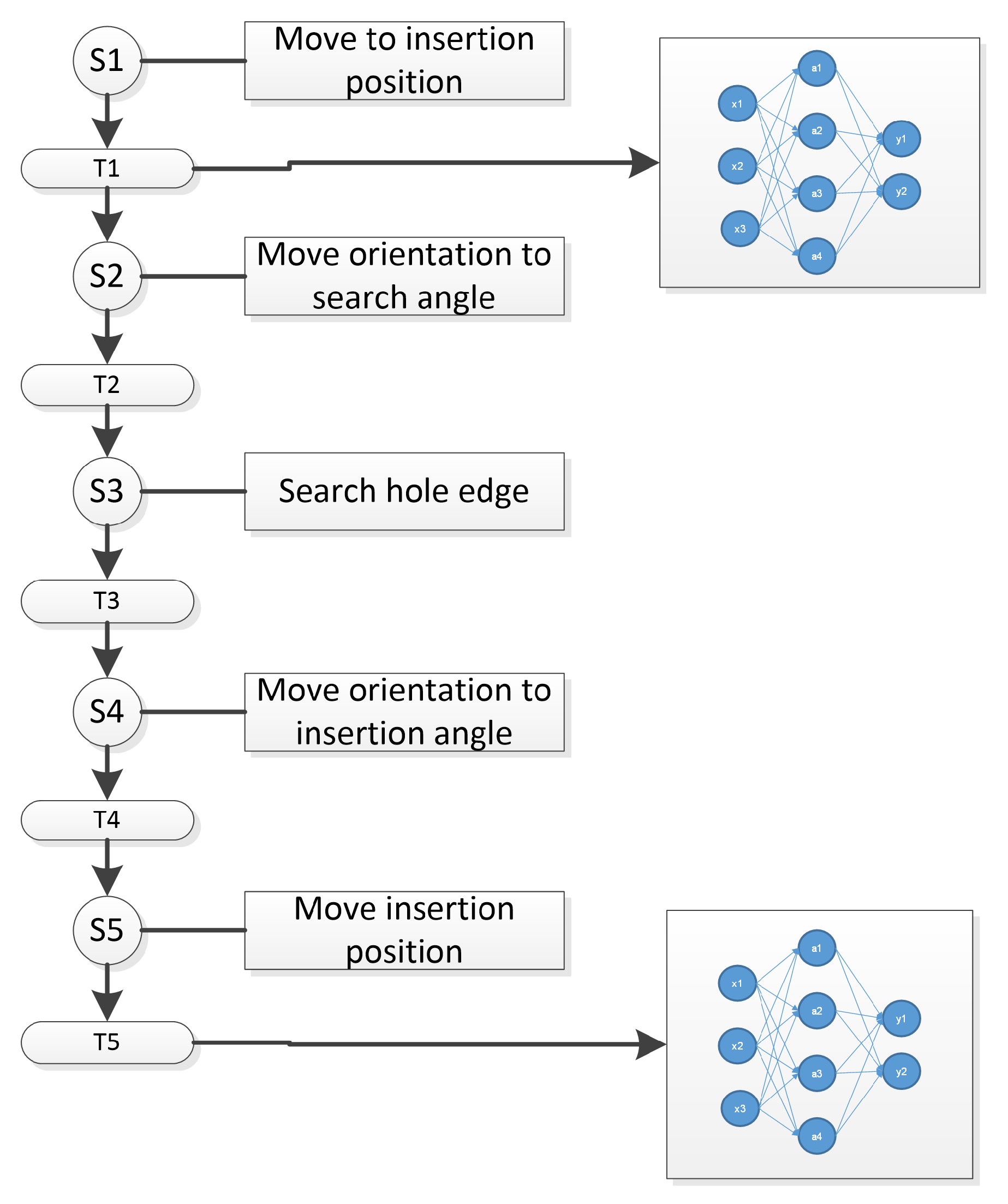
To safely perform constraint movements with the dual arm robot, considering the control strategy for a discrete event system, two primitive movement functions are defined to avoid damage to the system. This can be described as follows:
where
is a function that starts the robot movement whenever the force
f is less than the maximum limit
and the movement stops whenever the force
f is greater than the limit
. For the case of the
, the function starts or stops the robot movement according to the conditions based on the limit
. These primitive movements are used for every step of the sequence in
Figure 3 according to logic constraints.
Step 1 moves the robot to the error position as shown in
Figure 1a. The error position is selected randomly. On step 2, the orientation is selected according to the error position as shown in
Figure 1b. In step 3, the peg is moved along the X-Z plane in the -Z direction until a lateral contact force is reached
Figure 1c, step 4 sets the orientation to be aligned with the hole
Figure 1d and, finally, step 5 moves the peg towards insertion
Figure 1e.
The sequence is repeated for each error position, gathering contact state information to make the data set for training, testing, and to make a validation data set.
3.3. Data Set Analysis
In order to analyze whether the data set can be used for learning the contact states, the t-distributed stochastic neighbor embedding (t-SNE) method is performed. As can be seen in the results, this graphical representation helps find out whether there are separable classes. The t-SNE [
35] is a nonlinear dimensionality reduction technique that helps in visualization of data in a low dimensional space.
3.4. Standard Automation Logic Rules
In the case of programming a standard automated program, logic rules are used to trigger transitions among sequence steps. Variable limits or thresholds to classify F/T data are presented in [
7,
23]. To find whether this method can be used for this research, the data set is analyzed using statistical measures. Thresholds are used as logic conditions to classify the F/T input values in accordance to the next equation:
where
corresponds to the mean of the momentum in any axis and
corresponds to the standard deviation of the momentum in any axis. This defines the value of the superior and inferior limits:
and
.
3.5. Deep Neural Network Definition
Deep Neural Networks can map the force/torque signals to the defined error position class. These classes can also map the corresponding robot actions. Contact states are defined as quasi-static motion, which means that velocity of the motion is not taken into account.
For this investigation, the contact states that are under analysis are those that occur during the first assembly stage: the initial approach between peg and hole. Although the error position during this stage is unknown, a set of error positions can be defined to convert the case into a classification problem.
The sensors deliver x, y, z components for the force and momentum. Instead of using separate sensor signals, a single F/T vector of 12 features is proposed as shown next:
where
represents the force/torque vector, and the sub-indexes
,
and so on, represent the component from sensor 1 or sensor 2.
Then, a DNN model as expressed in the next equations is defined experimentally by changing parameters and hyper-parameters to reach an acceptable accuracy during the training and testing.
where
corresponds to the number of features or inputs,
y correspond to the number of outputs or classes,
h correspond to the number of hidden layers, and
n to the number of hidden units.
In order to pre-process the data set for training the DNN, a standardization process corresponding to the following equation is executed.
where
is the normalized sensor features,
X is the input feature,
the mean of each feature in the data set, and
the standard deviation of each feature in the data set.
A second DNN model is designed to classify basic contact states such as orthogonal contacts in all axes X, Y, Z. That means that the second DNN model will have the same 12 input features and 5 outputs corresponding to the actions: move to , move to , move to , move to , and move to the insertion position . This model classifies the contact states during the insertion step. In any case, a small deviation causes a contact state force that commands the robot to stop insertion and align according to the second DNN model output.
The trained DNN model helps the system classify the contact states caused by the error position. This classification selects the relative position to which the robot should move next. Other algorithms are also trained and tested with the same data set to compare the performance.
3.6. Dnn Evaluation and Implementation on the Robot Controller
For the purpose of evaluating the DNN performance, different data sets were generated running the same sequence on different dates. The trained model is packed and loaded to run an offline validation test.
The DNN model is then packed as a computational library to be integrated into the robot controller. Thus the robot controller is programmed using the robot operating system (ROS). The libraries were programmed in python and packed as a Service-Node. The force/torque vector is received and processed running the DNN model. The result is sent back to the main control program that processes the data in the sequence logic.
3.7. Error Recovery Sequence
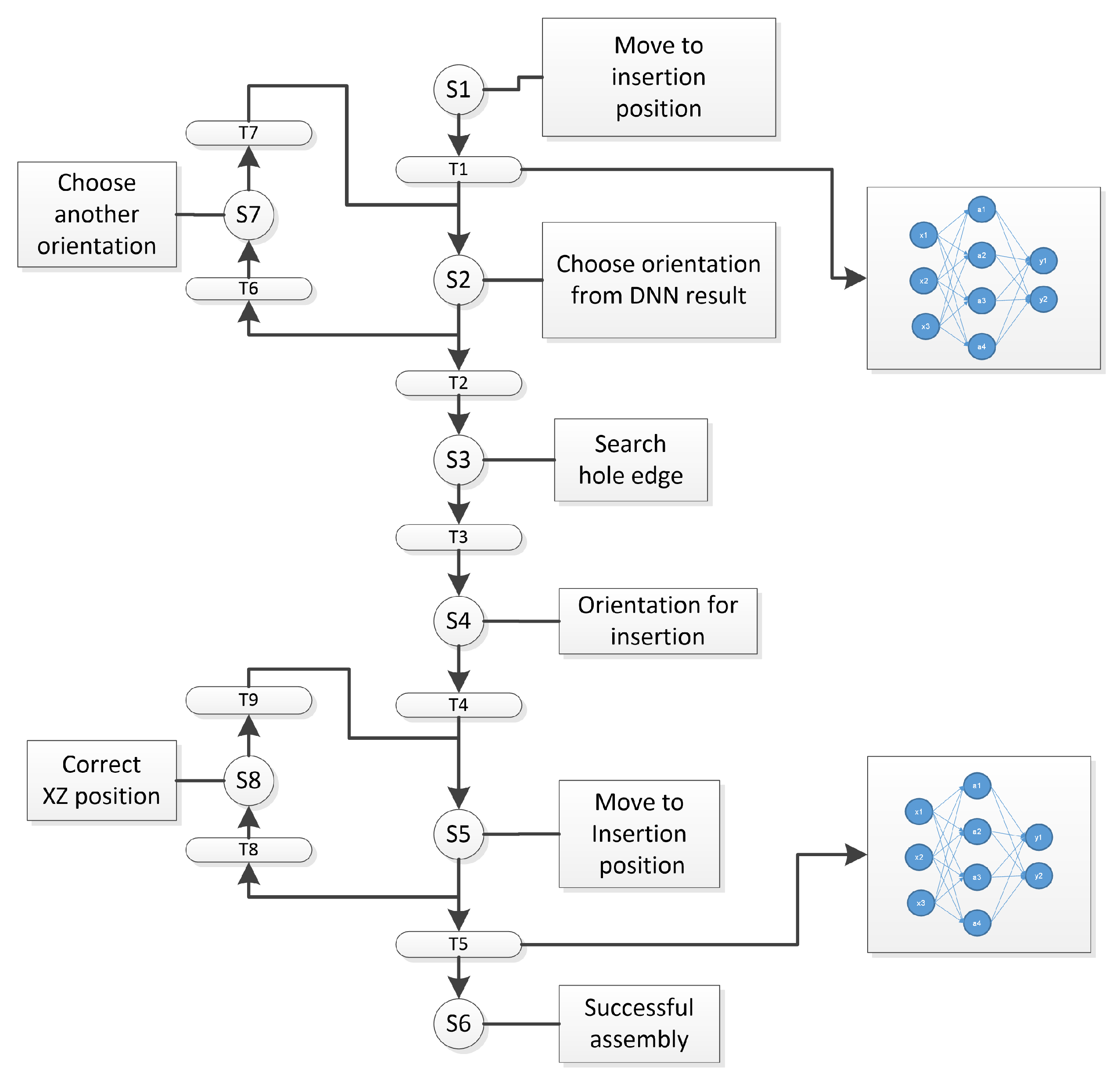
Since the DNN models present misclassifications in a real scenario, the assembly sequence is strengthened by adding logic constraints in every transition between steps. Two repetition cycles are added to the sequence. The first is represented as step S7, which repeats an orientation selection in case that the first DNN model outputs a wrong class, causing different contact states conditions. This can be identified and then triggers transition T6 to start this correction cycle.
For the case of the final insertion step S5, in case the insertion forces exceed the defined limits, the logic conditions will trigger T8 to start the adjustment cycle S8, where the second DNN model outputs a robot action that moves the peg to a center position.
This is one of the strengths of a discrete event system, that any step can be adjusted without modifying the whole control strategy. This new sequence program would lead the system to increase the rate of successful assemblies.
Figure 4 shows the petri-net that represents the recovery sequence.
The rule for trying another orientation after the first contact step is defined as follows:
The rule for aligning the peg during the insertion step uses a DNN trained with basic contact states in order to output a reaction movement according to the predicted F/T pattern. The logic rule is described in the
Table 1.
The first four patterns consider X and Z axis movements for error correction and for the pattern # 5; no error correction is commanded in the X-Z plane but there is a movement in the Y axis to continue insertion.
3.8. Validation Process of the Methodology
A validation process of different data sets is executed and the results are compared with the training set. A comparison of threshold methodology of single sensor data with DNN single sensor data, and then DNN with dual sensor data, is also executed.
A counter variable is set to limit the number of iterations or attempts in the assembly sequence.
In order to evaluate the performance of the machine learning algorithms, the Exact Match Ratio (MR) [
36] as presented in the next equation is used to report experimental results.
where
n is the sample number and
is a logic function of the correct classification of the sample.
Once the DNN models are trained and integrated into the assembly sequence, Success Ratio (SR) is used to evaluate the effects of using deep neural networks with one sensor and a double sensor in the automated cycle.
is defined as follows:
where
is the Success Ratio,
is the successful assembly that is true if the peg position
at the end of the cycle is greater or equal than the defined insertion position
and
n is the sample number.
4. Experimental Results
4.1. TestBed
The robotic testbed is composed of an industrial robot assembly cell that includes a dual arm robot SDA20D with two 7 DOF articulated arms and 1 rotating base giving a total of 15 DOF (degrees of freedom) as a whole system
Figure 5. The robot controller is a DX100 with Ethernet port.
The maximum payload is 20 kg per arm, and repetitive positioning accuracy ±0.1 mm. Mounted in each arm are the force/torque sensors in a range with ±300 N and Torque Nm with 3 Cartesian components for each magnitude with a maximum data stream of 100 Hz for all component signals. Noise around N and Nm. Recommended threshold 5 N and Nm maximum.
Both sensors are connected to an RS-485 to USB converter that sends the data to a Raspberry pi 3 running Robot Operating System (ROS). The parts to be assembled are a circular peg and hole in stainless steel with diameter of 40 mm and 39.9 mm for the peg with 50mm length. Both are fixed to the robot arms.
The main PC controller runs on Linux Ubuntu 18, and ROS Melodic is connected to the robot by the Ethernet 100 MB. A second PC controller runs Linux Ubuntu 20 and ROS Noetic, which runs the Deep Neural Network model as a service node. The robot has installed the MotoROS library that allows transfer of data via TCP/IP to the PC controllers and the Motodriver for ROS.
Figure 6 shows a representation of the setup.
4.2. Sequence Testing
In order to validate the proposed methodology, the previous experimental setup is used. The first goal in the experiment was to generate the data set of the force/torque signals from the two sensors. The assembly sequence is programmed in the computer to follow the 5 stages described in
Figure 1.
As described in the graphical representation of the sequence in
Figure 3, the robot arm that holds the peg moves towards the hole at a very slow speed; when the force limit is reached due to the first contact state, the robot will stop the movement and the contact forces are stabilized in a range of 1 or 2 s. With stable values of force/torque signals, the program gathers the information and saves a data file with the values of the error classification and the force/torque vectors from both sensors.
4.3. Data Set Creation
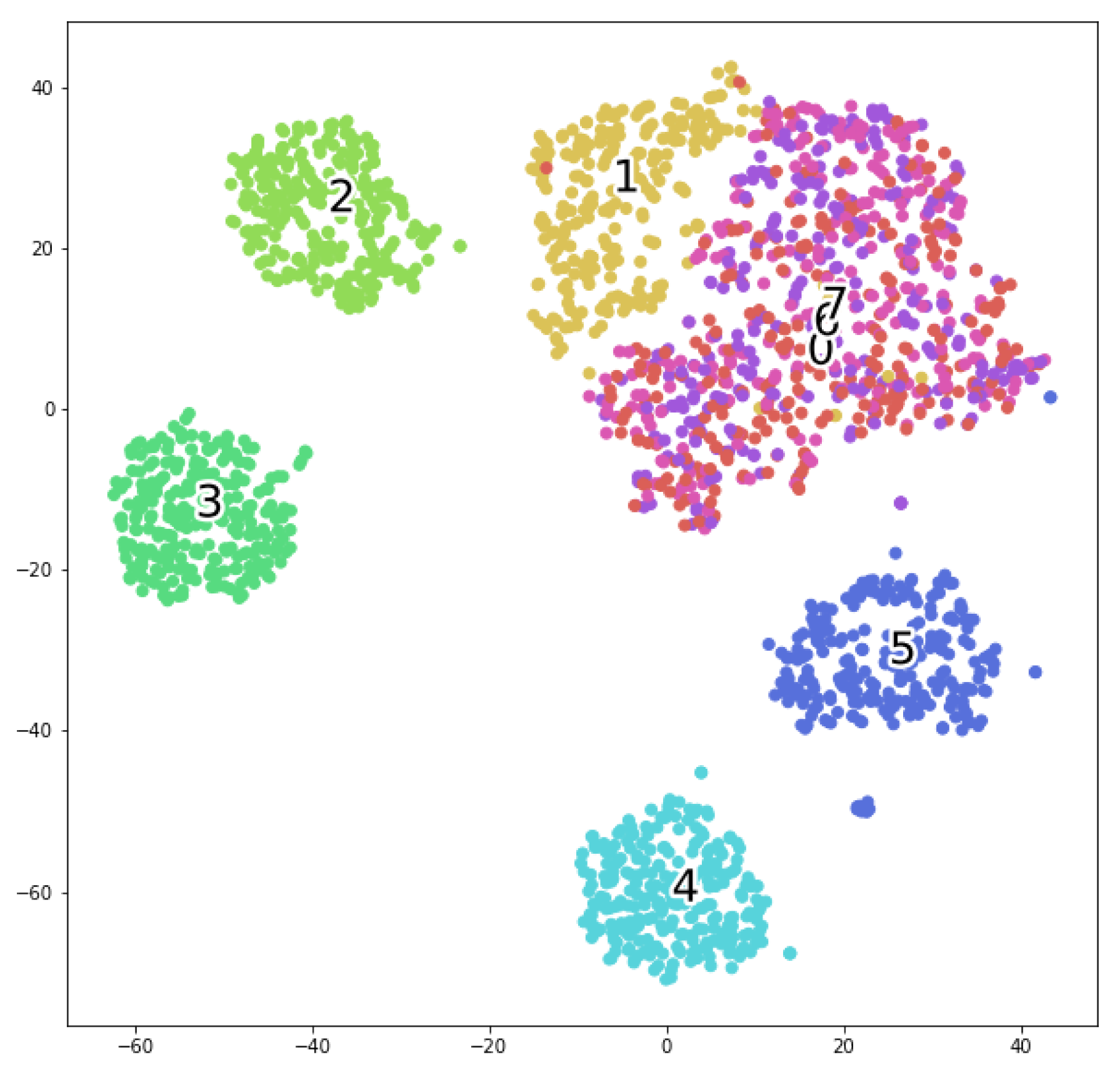
The database generated had a total of 2056 contact samples. The data set was analyzed using t-SNE (t- Distributed Stochastic Neighbor Embedded) technique to graphically visualize the separability of the features as shown in
Figure 7, where it shows how the data can be separated into the 8 classes. As it can be observed, the classes 0, 6 and 7 show very poor separability characteristics, meaning that most of the misclassifications happen on these corresponding positions, meanwhile the other features seem to be separable.
Additional databases were generated in order to have validation data sets. The number of samples for the validation data sets are reported in Table 4 and start from 35 samples to go to up to 240 samples.
4.4. Standard Automation Rules Results
For comparison purposes, the threshold is the first classification algorithm, and it consists of statistics metrics that define thresholds based on momentum
and
as decision constraints for the robot movements during the assembly cycle. Values of the thresholds obtained are presented in
Table 2.
A testing algorithm that runs the data set into the threshold comparisons was used to define whether the force/torque information corresponds to a certain defined class. The Equations (10) and (11) defined the threshold limits.
4.5. Deep Neural Network Training and Comparisons
The design of the neural networks was done through iterative testing where the initial configuration was based on empirical estimations. During the iterative design phase, different layer sizes and hyper-parameters were tested. The best result was obtained with the architecture of input layer 12 neurons, 5 hidden layers with unit size of 24, 48, 48, 48, 24 neurons, and, finally an output layer of 8 neurons. All input and hidden layers use an activation function . For the output layer, activation function is selected. The Loss Function is configured as Categorical Cross-entropy, and, as a learning optimizer, the Adam algorithm is selected.
The DNN model is programmed using Python libraries and Tensor-flow Keras [
37]. Then, the data set is divided into a 70/30 relationship for training and testing in 180 epochs. The data set contains the force/torque values of the two sensors. It must be considered that every time the DNN model is trained, even with the same data, different results of performance are expected.
The performance of the algorithm for training/testing is shown in
Figure 8 and
Figure 9. These graphs present the accuracy of the DNN, where the blue line represents the training data and the orange line the testing data. As seen in the one sensor case, the test data fits only up to 0.8 of the value during the 180 epochs, while the training data continues to fit the model. In the case of one sensor, the model implemented in the robot controller will present at least 20% of errors in classification.
On the other hand, the graph that corresponds to the two sensors shows the training and testing data with a high accuracy value. These results show a clear advantage to using two sensors rather than one.
Some other machine learning algorithms based on the sci kit-learn [
38] were designed to train/test different classification techniques and compare how well they fit the data. A list of tested machine learning algorithms with this data set is presented as follows:
Random Forest
K-Nearest Neighbors
Decision Tree
Multi Layer Perceptron
Deep Neural Networks
In order to demonstrate the difference between using only one F/T sensor versus two F/T sensors, the classification model uses either 6 features of the peg sensor or the 12 features of both peg and hole sensors.
To show the results of the training/testing of the machine learning models, a comparison of their performance is presented in
Table 3. It can be seen that the threshold algorithms based on statistical metrics performs worst. The best model corresponds to the Deep Neural Network followed by the Random Forest. The metrics reported in the table consider the accuracy defined as the number of correct predictions divided by the total number of predictions. The second metric is the F1-Score that represents the harmonic mean between precision and recall metrics.
4.6. Validating the DNN Models
The model was tested using extra data sets gathered after the main training data set acquisition. Using the same automated program, these new data sets with fewer contact samples were used as validation for the trained DNN model. The data sets start from 35 samples to got to 240 samples as shown in
Table 4.
The algorithm to validate the trained model considers the same values of mean and standard deviation of the train data set. The Equation (
12) is used to standardize the validation data sets. Then, the validation data set is used on the python Tensorflow Keras program to evaluate the correct classifications versus the incorrect classifications according to the Exact Match Ratio defined in (17).
Table 4 summarizes the accuracy results for the one sensor and two sensors. As shown in the results, there is a clear advantage to using two sensors rather than one sensor.
4.7. Testing on the Dual Arm Robot
In order to test this methodology in a real scenario of operation with the dual arm robot, the automated recovery program in
Figure 5 is executed. Two computers were used to run the experimental setup, one computer ran the automatic sequence and sensor acquisition. The whole controller is programmed in C++ running on ROS using Moveit packages and libraries to perform Cartesian commands on the robot.
The second computer that runs the service node receives the F/T data as an array of twelve elements that is computed and, at the end, gives back the class prediction. This prediction
is used in the assembly sequence to define the next orientation angle or movement in the corresponding direction to find the next contact states of the sequence.
Table 5 shows the corresponding orientation angles according to the predicted class.
The last experiment considers the validation of the full assembly cycle. Logic rules used as transition constraints between the steps. The full cycle F/T data is presented in
Figure 10 where the different steps and their corresponding F/T pattern can be seen. From free motion, the sequence evolves to the frontal contact state. The second step changes the orientation. The next step searches for lateral contact of the peg into the hole. At the end of the assembly sequence, the insertion phase shows a little deviation that exceeds a force limit value, which triggers the last DNN model. Reaction motions are selected according to the F/T data pattern and the DNN output. As the cycle continues, the patterns are detected and the position adjustment drives the F/T towards minimum values to lead the final assembly.
For these experiments a very slow motion is considered for safe contacts and to avoid any possible damage on the mechanical systems of the robot. Therefore, the time constraints for these experiments are not taken into account.
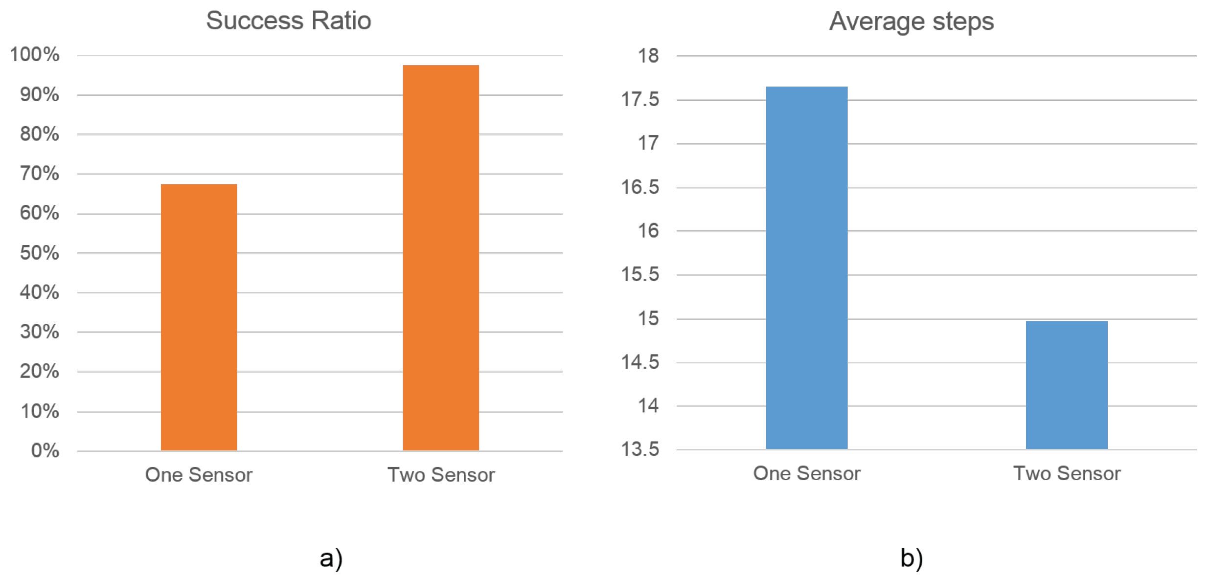
Finally, in order to compare the differences between the success ratio of assemblies using one sensor and using two sensors with two DNN’s as classifiers, the complete assembly experiment is reported in
Table 6.
These results show that the whole experiment executed 40 assembly insertion attempts, where the number of sequence steps needed to finish the insertion is counted, after which the average number of steps for the total of assembly attempts is reported as a comparison metric. The Success Ratio, is the average of the completed insertions in the experiment, is also presented.
The graphical representation of the results are presented in
Figure 11a, where one can see a better performance in the Success Ratio and in
Figure 11b the Average of steps for the two sensor configurations.
5. Conclusions
We have presented in this paper a methodology to evaluate the effects of using double force/torque sensors on the peg-in-hole assembly and deep neural networks. An assembly strategy was proposed, which was inspired on how a human would solve the positioning error of a peg-in-hole assembly. A discrete event controller designed to run the assembly sequence was designed as it would be programmed in an industrial automated robot cell. The purpose of this strategy is to achieve the assembly task despite the aleatory positioning error of the peg and hole.
A force/torque signal acquisition program was implemented to generate the data set for training machine learning algorithms. The automated data acquisition proved very efficient if different conditions are to be considered. This allows for testing different parameters before the final experiments. It also ensures that the contact states are gathered with the same assembly conditions as it would be in a normal automated cycle.
Off-line learning of the contact states is achieved by using deep neural networks. It was found that the publicly available machine learning libraries are a great evaluation solution to integrate in a ROS-based system. Despite the good results using DNN, we encourage evaluation other machine learning algorithms in the experimental setup. We noticed how the F/T signals are less separable in a certain geometric region presenting more false positives. Further investigation of this F/T signal behavior is needed.
Additionally, it is shown that the success ratio of the assembly process improved by the use of double force/torque sensors and deep neural networks. Although the comparison between different research works is not simple due to different experimental conditions, such as robot manufacturer, developing software and perception systems among others, the findings of this research presents a contribution on the evaluation of dual force torque sensors for assembly tasks.
The results obtained by using one and two force/torque sensors to classify contact states showed an improvement of 30% of Success Rate. The assembly strategy was based on a discrete event controller represented by a Petri-Net sequence diagram. Because this sequence diagram represents an automation program, we consider it feasible to test the methodology on industrial scenarios. However, this work does not take into account the overall assembly time due to safety considerations such as working with slow speed motions to avoid any damage to the robot. For an industrial application, this needs to be investigated.
There are still many conditions that need to be taken into account to implement this strategy in an industrial application. For example, changing shapes of the mating parts, the effects of adjustments such as speed, force limits and so on. These changes would affect the performance of the classifier due to the changes in the F/T behavior.
Future work considers different challenging scenarios such as testing different machine learning algorithms, the evaluation of different assembly parameters such as higher speed movements, higher force/torque limits, shape of the mating parts, the increase of uncertain conditions such as the number of aleatory error positions and so on. Evaluation of dual arm coordination strategies will also be investigated. Moreover, integration of grippers to manipulate the objects will increase positioning uncertainties that also need to be studied.


 ,
, 


