1. Introduction
The drive wheel’s main rolling problem is to provide it with a large traction force due to the high adhesion of its tire to the supporting surface. In our case, this is soil.
The action of the following forces causes the adhesion of the drive wheel tire to the soil: (i) frictional forces between the soil and the tire’s supporting surface; (ii) the force generated by the pressure of the tire vertical lug side on the soil; (iii) the force acting along the tire-soil contact surface located between lugs. The impact of these forces is accompanied by the displacement (sliding) of the wheel’s tire relative to the soil, commonly called slip.
From the above, it follows that slip should be considered as a combination of two processes: (i) slip due to circumferential deformation of the pneumatic tire (); (ii) slip due to soil deformation (
The circumferential deformation of an elastic pneumatic tire is caused by the torque applied to the wheel. The latter causes the wheel hub to turn at some angle relative to that part of the tire that is in contact with the soil. As a result, both the entire wheel and its axle, simultaneously rolling forward, partially move backward by a distance equal to the tire’s deformation. It should be noted that it is complicated to measure
separately [
1]. Because of this, in practice, this slip is most often determined together with slip
.
Of the above three forces, the last two carry out the most significant deformation of the soil. All three forces form the gross traction of the wheel. The nature of its change from slip depends on the type of soil.
Multiple studies proved that, on loose soils, the wheel’s gross traction reaches its maximum value as its slip increases. Further, in most cases, it remains practically constant [
2,
3,
4].
On firm soils, the nature of the gross traction dependence on its slip is somewhat different. At first, this force rises to its maximum value. Then, a further increase in wheel slip causes a decrease in its gross traction to some steady-state value [
5,
6,
7].
It turns out that, regardless of the soil type, in almost all cases, the maximum value of the wheel’s gross traction is achieved when its slip is 15% or more. However, due to the intensive slip of the wheel lugs relative to the supporting surface, there is a shift, crushing, and significant abrasion of the soil.
As a result, it loses its structure due to compaction [
8,
9], the permeability of air and moisture in it deteriorates [
10]. Simultaneously, restoring these soil properties to a normal state is a very time-consuming, labor-intensive, and expensive process.
Hence, it follows that the maximum value of the tractor wheels slip (
) should be such that the destructive effect on the soil is minimal. One way to decrease the tractor wheels’ slip is ballasting [
11,
12,
13,
14]. As practice shows, such a decision leads to an increase in soil compaction, which is undesirable and harmful.
In another variant decision to this problem, it is proposed to equip the wheeled tractor’s tires with lugs in the form of spikes or blades [
15,
16].
It should be noted that, in off-road conditions, this complication of the wheeled tractor can be justified. Under normal field conditions, the effectiveness of its application depends on the value of
. The value of this parameter can be such that the tractor operates with the slip of the wheels no more than
. It is realistically provided by doubling the tires [
10,
17] or decreasing air pressure in them [
13,
18,
19,
20].
The main problem above is determining such a value of which allows the tractor to develop high tractive properties without disturbing the soil structure.
One of the attempts to solve this issue was established [
11]; the soil cutting with the tractor wheel’s lugs occurred when slip varied from 10% to 17%. With this in mind, the article’s authors propose considering such wheel slip values as approximate limit values.
Simultaneously, these tractor wheel slip levels can and obviously are different in other soil conditions. Moreover, the maximum permissible value of
, in our opinion, should be such as to: (i) exclude a soil cutting in general; (ii) allow soil deformation (shearing or crushing) in the longitudinal direction only up to a specific limit. The latter was not established in [
11].
The article [
18,
21] proposed the following algorithm for decisions on this problem. In Ukraine, there is a state standard DSTU 4521: 2006 “Mobile agricultural machinery. Standard rates of impact on soil by undercarriage”. It establishes the requirements for limiting the vertical pressure (
, kPa) of the agricultural tractor’s wheels on the soil depending on its moisture content, density, and fieldwork period (spring–summer and summer–autumn).
Having applied this restriction to the effect of the wheel lugs side surfaces on the soil in the horizontal plane, we obtained an analytical dependence that allowed us to determine the value of
[
18,
22]:
where
—coefficient of soil bulk deformation, N m
−3;
—rolling radius of the wheel, m;
—rolling resistance coefficient.
A feature of Equation (1) is that it allows one to determine the value of the maximum permissible wheel’s slip without cutting the soil by the lugs and with such a level of their pressure on it in the longitudinal direction, which is limited by the value of .
Besides, this equation allows establishing the regularity of influence on the value of
for such soil parameters as the coefficient of bulk deformation
and the coefficient of rolling resistance
. The latter’s influence on the maximum permissible of the wheel slip with the constancy of the remaining parameters included in the Equation (1) is described in the articles [
18,
22].
At the same time, functional dependence is not yet determined. It is essential for practice since the bulk deformation coefficient () is rather closely correlated with its density. Obviously, there is a specific relationship between the values of the parameters and as well, however, its point is not yet known.
Finally, to determine the maximum permissible slip value of the tractor wheels, it is essential to know the regularity of this process’s influence on the soil structure. However, the methodology for assessing such effect is not yet developed.
An attempt to provide answers to these problematic questions i = was the aim of this article.
The results obtained in this case make it possible in practice to organize the operation of tractors with such slipping, which does not lead to a violation of the soil structure. This is very important from the standpoint of preserving its fertility.
2. Materials and Methods
To assess the effect of tractor slip on the soil, the coefficient of its structure
was adopted. To define it, we proposed the following equation:
where
—mass of agronomically valuable soil aggregates in the soil sample, kg;
—total mass of soil sample, kg.
The agronomically valuable soil aggregates were considered those with a diameter of 0.25–10 mm [
23].
Before field studies, the initial value of the soil structure coefficient as well as its moisture and bulk density in the 0–10 cm layer were determined. The studies were carried out in the Zaporizhzhia district’s conditions (southern Ukraine) on dark chestnut soil with physical clay content up to 55%, physical sand up to 35%, and humus up to 3%.
To determine the coefficient , the dry method of sieving the soil was used. For this purpose, a kit of three sieves stacked, one on top of the other, was used. The top sieve had holes 10 mm in diameter. The hole diameter of the middle sieve was 1 mm.
This decision was due to the following considerations. Firstly, holes with a diameter of 0.25 mm are difficult to implement and are prone to clogging with soil. Secondly, we used the coefficient to assess the influence degree of tractor wheels slip on the soil structure. Considering this, the middle sieve holes’ diameter equal to 1 mm was entirely acceptable and technically feasible. The bottom sieve was without holes.
The soil sample mass was equal to 1 kg. After handshaking sifting, the soil remained on the upper sieve, the particles of which had a diameter of more than 10 mm. Soil aggregates with a diameter of more than 1 but less than 10 mm remained on the middle sieve. Soil particles less than 1 mm in diameter were spilled onto the lower sieve.
Thus, the agronomical valuable soil aggregates were concentrated on the middle sieve. Since, in our case, , the soil mass in this sieve, and , determined in kg, were automatically selected as follows from Equation (2), the value of the soil structure coefficient was .
For the weighting of the selected soil samples, we used an SF-400-D3 (PROK, Ukraine) electronic laboratory scale with a weighing limit of 3 kg and an accuracy of ±0.1 g.
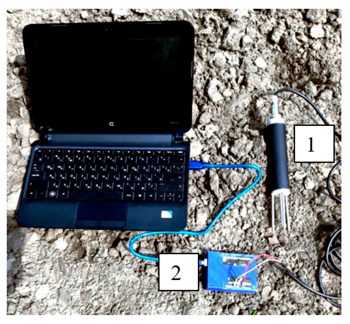
The measurement of soil moisture in the 0–10 cm layer was carried out with an SHS-1 device (Kharkiv, Ukraine), which was connected to a laptop via an Arduino Uno device (China) (
Figure 1). The error in measuring soil moisture’s absolute value with this device did not exceed ±1%.
The data received from the Arduino Uno were formed on the laptop using the CoolTerm program in a form suitable for processing in the Microsoft Excel environment.
After 100 soil moisture measurements, carried out every 3 m along the field diagonal, its average value was calculated.
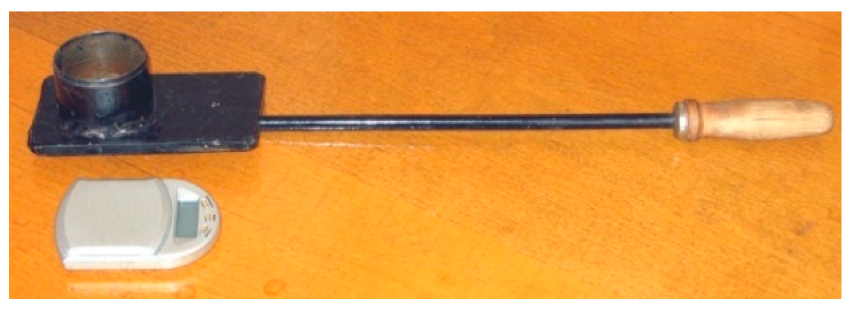
Measurement of soil bulk density was carried out as follows [
21]. A soil sample was taken with a 28.35 cm
3 cylinder (
Figure 2) and weighed on the scales. The latter were configured to measure in ounces (oz.). Because
, the scale displayed the soil mass corresponding to its density in g cm
−3. After 30 soil bulk density measurements, carried out every 3 m along the field diagonal, its average value was calculated.
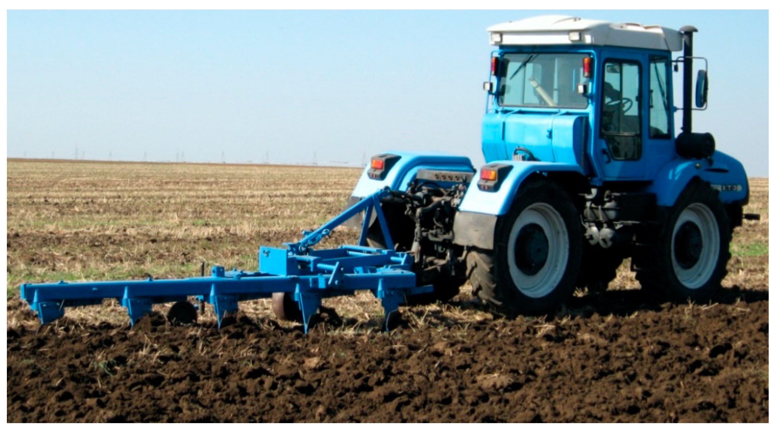
The influence of the tractor wheels’ slip on the soil structure coefficient was studied with a plowing unit. It included the HTZ-17021 (Kharkiv, Ukraine) 4WD tractor and the five-furrow plow (
Figure 3). The main technical characteristics of this plowing unit are presented in
Table 1.
The plowing unit’s research program provided three modes of its movement with wheel slip: (i) up to 15%; (ii) up to 20%; (iii) up to 25%. For these three levels of slip, the required plow traction resistance (
) was determined according to the passport traction characteristics of the HTZ-17021 tractor. To provide approximate
values for each level of tractor’s slip, the plowing depth (
h, m) was changed. The required value of this parameter was determined from the equation:
where
k—plow specific resistance coefficient. For soil conditions of south Ukraine, the mean of this parameter was equal to 60 kN m
−2.
The plowing depth calculated using the Equation (3) was used to adjust the plow accordingly.
For studies of the plowing unit movement in the field, 9 sites (3 test conditions with 3 replicates for each of them) were prepared. The length of each site was equal to 300 m. The first 25 m of each site were used to accelerate the plowing unit. On the site
during the time
, it carried out a working stroke with a given plowing depth. The time
was measured with an FS-8200 electronic stopwatch. Its measurement accuracy was equal to ±0.1 s. Then, the operating speed of the plowing unit
Vp was calculated by the equation:
The last 25 m of each site were used to stop the plowing unit. On the same area in the track of the tractor rear wheels, soil samples were taken to determine its structural coefficient at the corresponding value of slip HTZ-17021. To determine the coefficient in three repetitions, the above method and Equation (2) were used.
Tractor wheels slip was calculated using the equation:
where
,
—number of a tractor’s driving wheels revolutions with idling and working strokes of plowing unit, respectively;
,
—speed of the tractor with draft traction and without it, respectively.
For most agricultural tractors with sufficient practice accuracy, the ratio
on their main working gears can be taken as approximately constant, i.e.,
. For the HTZ-17021 tractor, this ratio was equal to 0.21 (see
Table 1).
In each experiment, the number of revolutions of the tractor’s rear wheels () was recorded using IMD-2N rotary magnetic encoders (IMD Ltd., Kyiv, Ukraine) with the following main technical features: 10–30 VDC voltage supply and ±0.15° absolute accuracy. Its electrical signals entered into an analog-to-digital converter and then to the laptop.
Having determined the values of , , and , HTZ-17021 wheels slip was calculated from Equation (5). The influence of this parameter on the soil structure coefficient was estimated from the obtained experimental dependences .
3. Results and Discussion
Analysis of Equation (1) shows that the slip of the tractor wheel depended on only one constructive parameter of a tractor—the rolling radius of the wheel . In real conditions, the greater its value is, the more significant the wheel’s contact area with the supporting surface is, e.g., soil.
However, in such a case as this, it was possible to take a correspondingly higher value of the allowable pressure
. Taking into account the growth of this parameter while increasing the wheel radius
, we could assume in the first approximation that the ratio of the values
and
remained practically constant, i.e.,
Having taken this into account, the maximum permissible value of the tractor’s wheels slip, as shown by Equation (1), was determined by only three parameters of the soil. They were: (1) permissible pressure ; (2) soil bulk deformation coefficient ; (3) rolling resistance coefficient .
In Ukraine, the value of is regulated by the state standard DSTU 4521: 2006 “Mobile agricultural machinery. Standard rates of impact on the soil by undercarriage”. The maximum value of this parameter for the spring–summer period is .
Tractors of traction classes 30 and 50 kN are the most common in Ukraine and other European countries. The average values of their operating masses are approximately 8000 and 12,000 kg, respectively. In Ukraine, tractors of traction class 30 kN are equipped with tires 23.1R26, and traction class 50 kN are fitted with tires 28.1R26. The rolling radius of the wheels with these tires is .
The value of the soil bulk deformation coefficient () depends on its type, structure, etc. In southern Ukraine, for example, the average value of this parameter (determined by us) for dark chestnut soils is about .
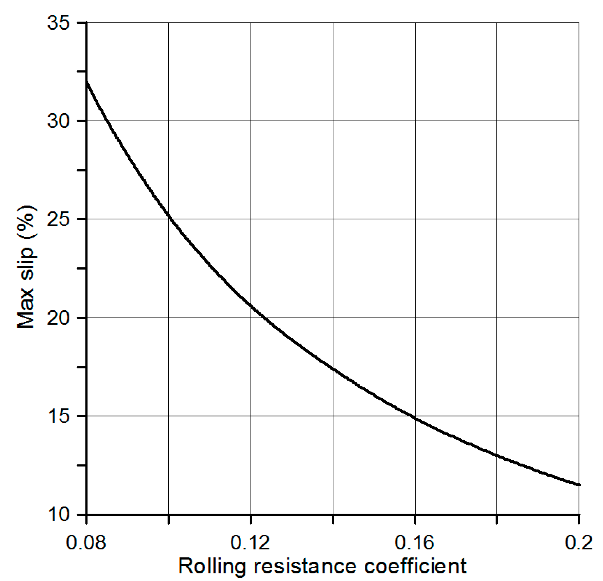
As for the coefficient of rolling resistance , its value in the field conditions is usually considered for two agrotechnical backgrounds: (1) stubble and (2) field prepared for sowing. If for the first of them (i.e., stubble), then, for the other (i.e., field prepared for sowing), this parameter varies from 0.12 to 0.20.
If we consider the separate influence of the coefficients
and
on the value of slip
), then we obtain the following result. The analysis of Equation (1) shows that increasing the rolling resistance coefficient (
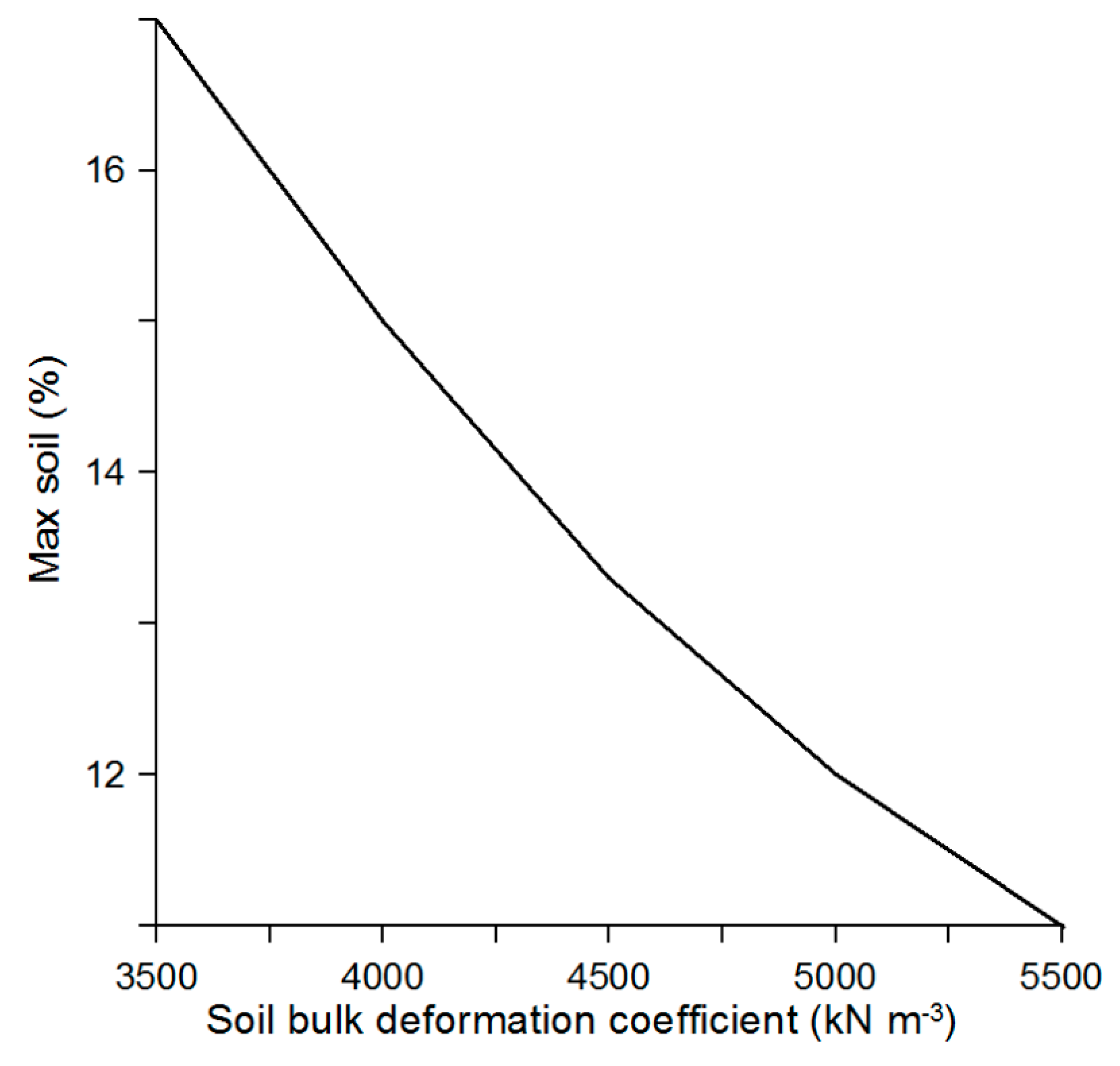
Figure 4) and the soil bulk deformation (
Figure 5) requires less value of the slip
.
Function
(
Figure 4) was obtained at
,
,
, and
[
22]. Calculation of the equation
was conducted at
,
,
, and
.
It should be noted that
Figure 4 shows the dependence of the coefficient
not on the operating tractor wheels slip but the maximum allowable slip
, which did not lead to a destroyed soil structure and was determined from Equation (1). Indeed, the larger the coefficient
was, the lower the strength of the soil was, and the less admissible the tractor wheels slip (
) could be realized on it.
Simultaneously, if the first result (
Figure 4) is, in principle, logical, then the second one (
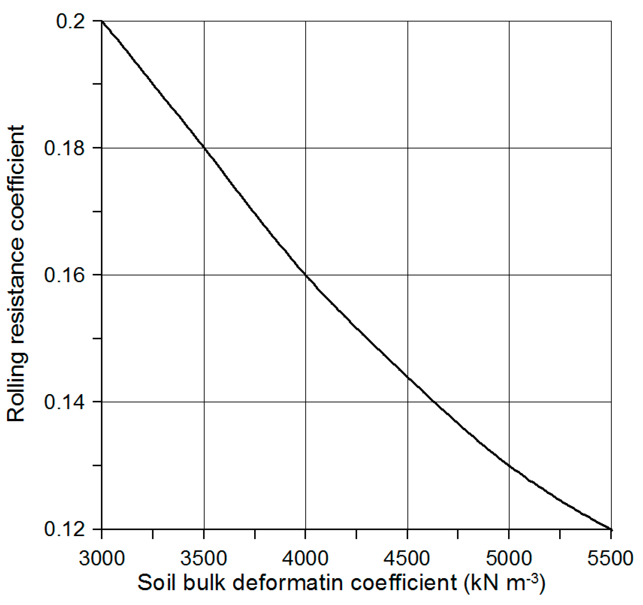
Figure 5) is not. The reason for this disagreement is the interrelationship between the coefficients
and
. The analysis of the Equation (1) and the research results of other authors [
5] show that the larger the soil bulk deformation coefficient is, the lower value of the rolling resistance coefficient is (
Figure 6).
Really, the value of the coefficient
, as is well known, is larger for density (solidity) soil. In this case, it had less value of the coefficient
[
7].
Practically, this means that an increase/decrease in the rolling resistance coefficient’s value is compensated by a corresponding decrease/increase in the value of the soil bulk deformation coefficient. As a result, the value of the maximum slip is determined only by the accepted values (but not variations) of the coefficients mentioned above and by the value of the ratio (6).
It should be remembered that changing the parameter to a greater or a lesser side should not have a significant effect on the value of . In this case, it was possible to change (i.e., increase or decrease) the value of the parameter in such a way that condition (6) was correct.
It follows from Equation (1) for such soil and tractor characteristics as , , , and , that the maximum slip of the tractor’s wheels should not exceed 15%. If the initial data , , , and differed from these, then the maximum slip value was different as well.
For practice, it is interesting to know how correct Equation (1) is. Under real test conditions on dark chestnut soil with a bulk density of 1.29 g·cm
−3 and a moisture content of 12.4%, the initial value of the coefficient of its structure
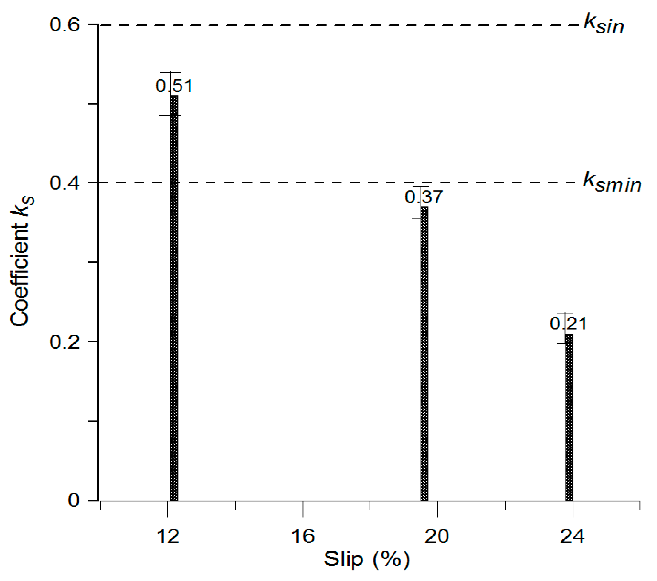
was equal to 0.6. The minimum value of this coefficient
at which soil structure was considered satisfactory was equal to 0.4 [
23].
If the value of the coefficient is in the interval between and , soil structure can be considered satisfactory.
Experimental studies showed that, when the wheels of the HTZ-17021 tractor slipped 12.2% (plowing depth 0.26 m), the coefficient of soil structure
was equal to 0.51 (
Figure 7). This was slightly less than the original value
but more than the minimum acceptable
.
Simultaneously, when the tractor wheels slipped 19.6% (plowing depth 0.29 m), the soil structure coefficient decreased to 0.37. This meant that soil structure deteriorated and passed into the category of unsatisfactory.
The soil quality became even worse when the tractor wheels slipped at 23.9% (plowing depth 0.32 m). In this case, agronomically valuable soil particles in the HTZ-17021 track were no more than 21% (see
Figure 7).
Hence, it follows that, to preserve the soil structure, the tractor wheels’ slip should be strictly limited to the value determined from equation (1). For the soil conditions described in this work, the value of should not exceed 15%.
4. Conclusions
One of the most important parameters that characterize a wheeled tractor’s traction-coupling properties is its slip when operating in a particular machine-tractor unit. To reduce destructive effect on the soil, the tractor’s wheels’ maximum permissible slip should not exceed the value calculated by the Equation (1).
For the soils average bulk deformation coefficient at , the average value of the rolling resistance coefficient at 0.16, and the ratio value of the permissible soil pressure to the rolling radius of the wheel at the maximum permitted value slip of the tractor wheels should not exceed 15%.
Experimental studies confirmed the validity of Equation (1). When tractor wheels slipped more than 15%, the aggregate state of the soil deteriorated. Under experimental conditions, even with a value of the parameter δ close to 20%, the actual value of the soil structure coefficient 0.37 was less than the minimum permissible (0.4). With wheel slip close to 25%, this coefficient’s value was even less, which cannot be acceptable in practice.


 ,
, 


