Article

Influences of the Water Cut of Pumping Oil and the Mineralization of the Associated Water on the Rate of Sludging

Scientific and Educational Center of Geology and Development of Oil and Gas Fields, Perm National Research Polytechnic University, 614990 Perm, Russia
*
Author to whom correspondence should be addressed.
Appl. Sci. 2021, 11(15), 6678; https://doi.org/10.3390/app11156678
Submission received: 16 June 2021 / Revised: 16 July 2021 / Accepted: 19 July 2021 / Published: 21 July 2021
(This article belongs to the Topic Enhanced Oil Recovery Technologies)

Abstract

:
The problem of the formation of organic deposits on the inside surfaces of borehole equipment and oilfield pipelines, which is urgent for all active oil fields, was considered in the study. The formation of these deposits leads to decreased lifespans for oilfield equipment and accidents involving oil pipelines and wells. The aim of our work was to estimate the dependencies of the organic deposition’s formation-rate factor on the water cut of the investigated water–oil emulsion and the mineralization of the water phase. Examination via generation of asphaltene–resin–paraffin deposits on the surfaces of cold rods was carried out with a “Cold Finger” CF-4 unit. Coefficients of specific oil sludging, fluid sludging and rate sludging have been determined. It has been defined that in the definite oilfields, the rate of sludging does not increase as the water content in the emulsion increases. As water-phase mineralization increases, this value remains practically constant.

1. Introduction

The formation of asphaltene–resin–paraffin deposits (ARPD) on the wetted surfaces of downhole equipment and field oil pipelines is a frequent complication in the process of oil extraction [1,2]. The worldwide and Russian experiences of oil field development and exploitation provide evidence for the urgency of this problem [3,4,5]. In Russian deposits, the problem of ARPD formation is representative, the number of oil-producing wells is abnormal, due to ARPD amounting to 70% of their total [6,7].
The new and improved methods and technology for preventing deposit formation and deposit removal have identified the necessity for the examination and acquisition of new data about the mechanism of ARPD formation. Likewise, one requires correct estimations of the influences of different factors on the rate of deposit formation along the path of well-product motion—from the bed to the vessels of the depot [8,9].
Factors which affect the process of ARPD formation and its rate include the presence of asphaltenes, resins and hard paraffins in oil; pressure; temperature; oil current; evidence of an independent gas phase; water; and roughness of wetted surfaces [10,11]. Pressure reduction via the associated petroleum gas below the saturation pressure of the oil unbalances the system pathologically. As a result, asphaltene–resin agents (ARA) dissolved in oil begin to separate, forming primary substrate on the wetted surfaces of the downhole equipment. When the current’s temperature decreases to the temperature at which the oil can be saturated by paraffin (the temperature of paraffin crystallization), solid paraffinic hydrocarbons are also isolated from the oil and form particles of different sizes in the process of crystallization [12]. The larger particles are removed by the current, and the smaller ones in the process of mixing the fluid stick to the wetted surfaces under the influence of the adhesive strength and form the ARPD layer. The rate of the layer formation is substantially affected by the presence of the temperature gradient between the wetted surface and the current. As the temperature gradient rises, the intermolecular bonds between the microcrystals of paraffin and the surfaces are strengthened [13]. If the flow rate increases, shear stress affecting the ARPD layer can exceed the pressure defined by the adhesive strength [14]. In this case the particles of crystal paraffin are broken off the surface and removed by the flow [15].
Asphaltene–resin agents, through the process of deposition on metal surfaces, including those which are covered with paraffin deposits, promote the surfaces’ rugosity and make them hydrophobic [16,17]. Along with the minute rock particles and corrosion products, they promote hardening of the deposits formed. It has been determined that ARA influences the temperature of oil saturation with paraffin as well [18].
The presence of water in crude oil makes an impact on the character and the rate of ARPD [19,20]. Water increases the specific heat of the fluid and increases the hydrophilicity of the wetted surfaces, weakening the effects of adhesive forces [21,22]. In the process of water and oil emulsion (WOE) generation, minute globules armored by the crystals of paraffin, asphaltene and resin are involved in the process of ARPD initiation [23,24]. Small particles of free water in WOE can be also involved in the process of ARPD initiation.
The results of laboratory research concerning ARPD initiation, taking into consideration the water cut of crude oil and the degree of associated water mineralization, are presented in this work.

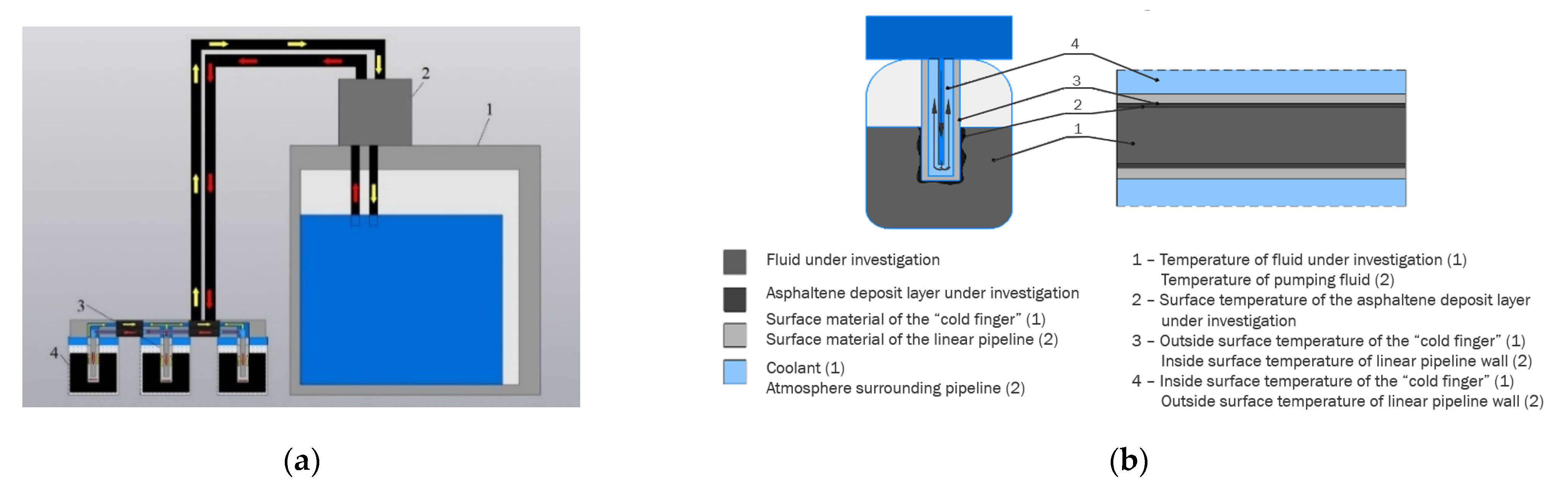
2. Materials and Methods

Analysis of the influences of the crude oil water cut and the degree of associated water mineralization on the rate of ARPD formation in the system of gathering production fluid was performed by the “Cold Finger” CF-4 unit. The diagram of this installation is presented below (Figure 1a) and includes: special containers for fluid (4), «cold» rods (3), the inner surface of which is cooled using a circulation thermostat (1) and a pump (2) to create a significant temperature gradient. This installation works according to the reverse piping principle (Figure 1b): inside the «coldrods» there is a cavity, at the bottom of which coolant flows. The «cold rod» is lowered into a special flask with the investigated fluid heated to the required temperature. At the bottom of flask is a magnetic stirring device. This setup allows one to simulate the movement of a unit volume of fluid in an oil pipeline.
Asphaltene–resin oils of oil fields «X» and «Y» (Perm krai) were used for preparing water–oil mixtures. Characteristics of the oils are given in Table 1.
Reservoir waters of oil fields in the territory of Perm Krai are calcium-chloride-rich (classification of V.A.Sulin). The produced reservoir waters (according to classification of V.S. Gurevich and N.I.Tolstikhin) are related to strongly brackish (3.5–10 g/L), low-concentration solutions (50–100 g/L), are high in salt (100–270 g/L) and have densities of up to 1180 kg/m3.
Associated water taken at the field pumping stations was used for preparing water–oil mixtures in the form of emulsions. The water samples had different densities and mineralization levels (Table 2).
Dynamic viscosity of WOE was determined via rotary viscosimeter: Rheotest RN 4.1. Maximum viscosity of WOE at the point of inversion for the oil of «X» oil field was derived at n v = 78% (1480 mPa∙c); for the oil of «Y» oil field—at n v = 63% (1830 mPa∙c) (Figure 2).

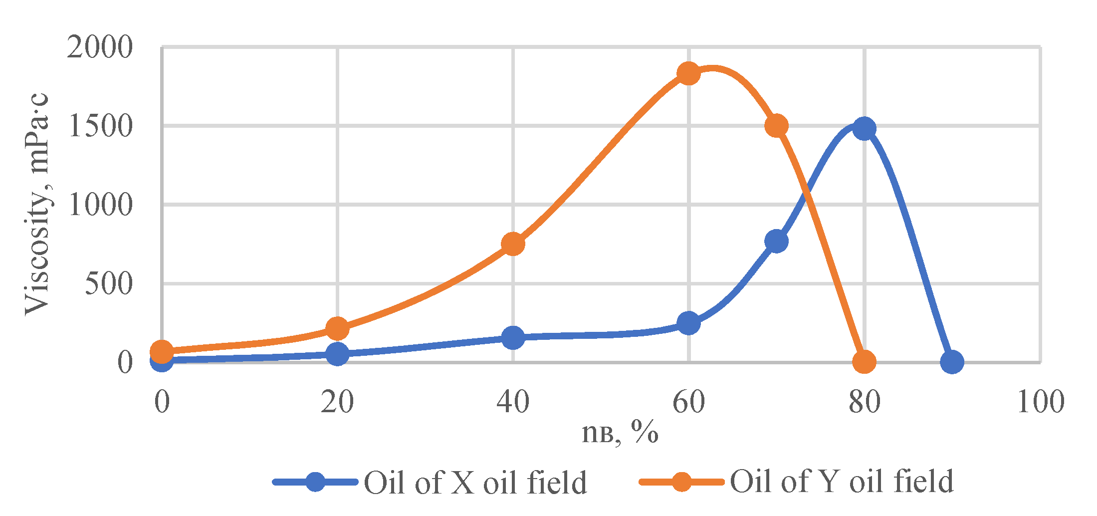
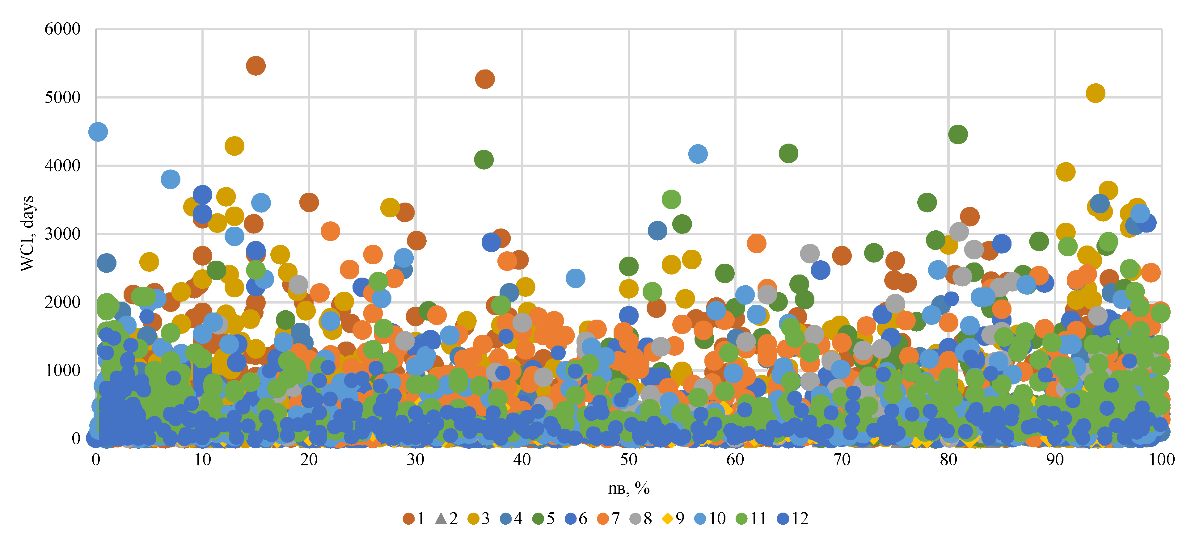
3. Results and Discussion

Samples of WOE were prepared by mixing in the required ratios the samples of oil and associated water for 5 min (700 rpm).
The resulting oil–water emulsions were characterized by high aggregate stability, which was explained by the high content of natural surfactants therein. No stratification of the emulsion was observed during the studies. In this work, two types of emulsions were investigated—water in oil and oil in water. The first type of emulsion takes place when its water cut is 60–80% and is characterized by significant viscosity, which increases with an increase in the proportion of water. When a certain water cut called the inversion point is exceeded, the phases are reversed, forming an oil-in-water emulsion. This emulsion is characterized by the dispersion medium being of low viscosity, which explains its lower aggregate stability.
The resulting samples heated in the water bath cup at 45 °C were examined with respect to sludging with constant agitation by the magnetic device at a rate of 500 rpm and a temperature of 5 °C for the cooling agent in the unit CF-4, for 2 h.
Each oil or water–oil emulsion’s ability to sludge ARPD on the fingers during the investigation was estimated by the coefficient of specific sludging for the oil (SSO) or for the fluid (SSF) according to expressions (1) and (2), respectively:
S S F = M 2 M 1 M n   · 100 %
S S O = M 2 M 1 M zh   · 100 %
where M 1 and M 2 masses of the rod before sedimentation and after the experiment, respectively, g; M n —mass of oil in the test sample, g; M zh —mass of liquid, g.
For the samples of the dry crude oil, the following values of SSO were derived: «X» oil—0.36%; «Y» oil—0.33%.
As can be seen from the graphs obtained, the change in the LOL index with an increase in the water cut of the emulsion was small. For fluid “Y” we can say that there was a minimal decrease in this indicator. In the figures, trend lines are point-by-point averages using theoretical values of the coefficient. For the SSF coefficient, these values were determined via expression 3. When forcing them, all the results of laboratory studies were taken into account. Considering these graphs, it can be noted that the nature of the change in the SSF value for some water samples deviates from this trend line, which is explained by the presence of errors in the operation of this laboratory setup.
In the figures, trend lines are point-by-point averages using theoretical values of the coefficient, which is calculated as such:
S S F = m ARPD · [ ρ v · ( 1 n v ) + ρ n · n v ] ρ n · ρ v · V z h   · 100 %
where m ARPD = M 2 M 1 .
The results of the experimental determination of sludging coefficients are given in Table 3.
At the maximum water cut, the coefficient of SSF for oil «X» is 0.28% (Figure 3a); for oil «Y»—0.24% (Figure 3b).
The SSO coefficient for oil «X», as the WOE water cut increases, grows from 0.36 to 1.37–1.77% (Figure 4a); for oil «Y»—from 0.33 to 1.49–2.19% (Figure 4b). Theoretical values of SSO were derived from expression 4:
S S O = m A R P D · [ ρ v · ( 1 n v ) + ρ n · n v ] ρ n · ρ v · ( 1 n v ) · V z h   · 100 %  
The trend lines shown in these charts were obtained from the analysis of all laboratory test results. In the case of the SSO value, the dynamics of its changes for all oil and water samples correlate with the direction of the trend line. Moreover, it is worth noting a significant increase in the value under consideration that appears, most likely, during the formation of an oil-in-water emulsion. Such a significant increase in the value of oil dehydration for the studied oils must be associated firstly with the inclusion of the aqueous phase in the sediments. That process, combined with a decrease in the proportion of the oil phase, caused a significant increase in the indicator under consideration.
The figures of sludging remain practically the same until the water cut reaches 60%, at which point the mineralization of the associated water included in WOE increased (Figure 5a,b).These figures also show trend lines, which are averaged values for water samples of a certain salinity. These trend lines slightly deviate from horizontal linearity, which confirms the lack of correlation between the parameters of sedimentation and salinity of the water phase.
Noticeable or even significant variations of sludging values resulting from changes in the water cut are most probably connected with the technological error of tests (incomplete high-viscous emulsion running off the fingers before weighting).
The rates of sludging in our investigation were evaluated by oil (RSO) and fluid (RSF) coefficients:
RSF = m A R P D 2 · V z h = 5 · 10 3 · ρ n · ρ v · S S F ρ в · ( 1 n v ) + ρ n · n v  
RSO = m A R P D 2 · V n = m A R P D · [ ρ v · ( 1 n v ) + ρ n · n v ] 2 · ρ v · ( 1 n v ) · V z h = 5 · 10 3 · ρ n · S S O
As seen in Table 4, the rate of sludging for fluid reduced by about 7% upon every 20% increase in the water cut. In other words, the reduction in the rate was not proportional to the increase in the water cut. Thus, the rate of sludging for oil increased with increasing water cut in WOE (Table 5). This effect obviously happened due to the intensive “capturing” of globules from the water–oil emulsion by the forming deposits.
The sludging rate coefficients are given in Table 4 and Table 5 for the example of water sample No. 1. The values of SSO and SSF coefficients were obtained using expressions (3) and (4). For the specified conditions, the ratio of SSO and SSF is equal to 1 / ( 1 n v ) ; the ratio of RSO and RSF is equal to [ ρ v · ( 1 n v ) + ρ n · n v ] / [ ρ v · ( 1 n v ) ] .

4. Conclusions

From the results of our research, the following conclusions can be drawn:
1. The rate of sludging (using the volume of fluid being pumped) did not rise as «X» or «Y» oil water cuts increased. This can be confirmed by an analysis of the well-cleaning interval (WCI) data of Lukoil–Perm limited company (Figure 6). In this figure, the numbers indicate various oil production workshops located throughout Perm Krai, which exploit many different hydrocarbon deposits. The MOP value reflects the time interval between treatment activities, and as can be seen from the figure, it does not depend on the water cut of the product produced.
2. As the associated water mineralization increases, the rate of sludging is not considerably changed.

Author Contributions

Conceptualization, K.V., V.M. and P.I.; investigation, P.I., K.V. and A.K.; methodology, K.V. and V.M.; project administration, P.I.; resources, K.V.; software, A.K.; validation, A.K. and V.M.; visualization, K.V.; writing—original draft, K.V. and A.K.; writing—review and editing, P.I. and V.M. All authors have read and agreed to the published version of the manuscript.

Funding

The work was carried out in the organization of the Lead Contractor as part of the R&D carried out with the financial support of the Ministry of Science and Higher Education of the Russian Federation (agreement number 075-11-2021-052 of 24 June 2021) in accordance with the decree of the Government of the Russian Federation: 09.04.2010, number 218 (PROJECT 218). The main R&D contractor is Perm National Research Polytechnic University.

Conflicts of Interest

The authors declare no conflict of interest.

References

  1. Towler, B.; Jaripatke, O.; Mokhatab, S. Experimental Investigations of the Mitigation of Paraffin Wax Deposition in Crude Oil Using Chemical Additives. Pet. Sci. Technol. 2011, 29, 468–483. [Google Scholar] [CrossRef]
  2. Burger, E.; Perkins, T.K.; Striegler, J.H. Studies of Wax Deposition in the Trans Alaska Pipeline. J. Pet. Technol. 1981, 33, 1075–1086. [Google Scholar] [CrossRef]
  3. Gawas, K.; Krishnamurthy, P.; Wei, F.; Acosta, E.; Jiang, Y. Study on Inhibition of High-Molecular-Weight Paraffins for South Eagle Ford Condensate. In Proceedings of the SPE Annual Technical Conference and Exhibition, Houston, TX, USA, 29 September 2015. [Google Scholar]
  4. Fan, K.; Huang, Q.; Li, S.; Zhao, D. Wax Deposition Study in a Cold-finger System with Model Oil. In Proceedings of the SPE/IATMI Asia Pacific Oil & Gas Conference and Exhibition, Bali, Indonesia, 20 October 2015. [Google Scholar]
  5. Hosseinipour, A.; Japper-Jaafar, A.; Yusup, S.; Ismail, L. Application of the Avrami Theory for Wax Crystallisation of Synthetic Crude Oil. Int. J. Eng. 2019, 32, 18–27. [Google Scholar] [CrossRef]
  6. Krivoshchekov, S.N.; Vyatkin, K.A.; Kochnev, A.A.; Kozlov, A.V. An approach to estimating the rate of organic deposit formation in a hollow rod string and selection of methods for deposit prevention. PeriodicoTcheQuimica 2021, 18, 164–178. [Google Scholar]
  7. Martyushev, D. Modeling and Forecasting of Paraffin Settings on an Existing Extractive Fund of Oil Deposits. Int. J. Eng. 2019, 32, 1704–1709. [Google Scholar] [CrossRef] [Green Version]
  8. Jalalnezhad, M.J.; Kamali, V. Development of an intelligent model for wax deposition in oil pipeline. J. Pet. Explor. Prod. Technol. 2016, 6, 129–133. [Google Scholar] [CrossRef] [Green Version]
  9. Sousa, A.L.; Matos, H.; Guerreiro, L.P. Preventing and removing wax deposition inside vertical wells: A review. J. Pet. Explor. Prod. Technol. 2019, 9, 2091–2107. [Google Scholar] [CrossRef]
  10. Ivanova, L.V.; Burov, E.A.; Koshelev, V.N. Asphalt-resin-paraffin deposits in production, transport and storage processes. Oil Gas Bus. 2011, 1, 268–284. [Google Scholar]
  11. Aiyejina, A.; Chakrabarti, D.P.; Pilgrim, A.; Sastry, M.K.S. Wax formation in oil pipelines: A critical review. Int. J. Multiph. Flow 2011, 37, 671–694. [Google Scholar] [CrossRef]
  12. Lyapin, A.Y.; Astakhov, A.V.; Mikhalyov, Y.P.; North, J.T. Study of the wax crystallization temperature in oil in order to reduce the formation of asphalt-resin-paraffin deposits. Sci. Technol. Oil Oil Prod. Pipeline Transp. 2017, 7, 28–35. [Google Scholar] [CrossRef]
  13. Ilyushin, P.Y.; Lekomtsev, A.V.; Ladeishchikova, T.S.; Rakhimzyanov, R.M. Evaluation of the effectiveness of the “cold stream” in the fight against asphalt-tar-resin-paraffin deposits. Bull. Perm Natl. Res. Polytech. Univ. Geol. Oil Gas Min. 2018, 18, 53. [Google Scholar]
  14. Venkatesan, R.; Nagarajan, N.R.; Paso, K.; Yi, Y.B.; Sastry, A.M.; Fogler, H.S. The strength of paraffin gels formed under static and flow conditions. Chem. Eng. Sci. 2005, 60, 3587–3598. [Google Scholar] [CrossRef]
  15. Lei, Y.; Han, S.; Zhang, J. Effect of the dispersion degree of asphaltene on wax deposition in crude oil under static conditions. Fuel Process. Technol. 2016, 146, 20–28. [Google Scholar] [CrossRef]
  16. Quan, Q.; Wang, W.; Wang, P.; Yang, J.; Gao, G.; Yang, L.; Gong, J. Effect of oil temperature on the wax deposition of crude oil with composition analysis. Braz. J. Chem. Eng. 2016, 33, 1055–1061. [Google Scholar] [CrossRef] [Green Version]
  17. Korobov, G.J.; Rogachev, M.K. Investigation of the influence of asphalt-resinous components in oil on the formation of asphalt-resin-paraffin deposits. Oil Gas Bus. 2015, 3, 162–173. [Google Scholar] [CrossRef]
  18. Mohammad-Zadeh Bahar, M.; Zaeim Mousavy, M.; Vafaie-Sefti, M. Compositional Modeling of Wax Formation in Petroleum Mixtures. Int. J. Eng. 2011, 14, 303–312. [Google Scholar]
  19. Prozorova, I.V.; Kirbizhekova, E.V.; Yudina, N.V. Influence of temperature and degree of water cut of oil on the composition of tar-resin-paraffin deposits. Oil Refin. Petrochem. Sci. Technol. Achiev. Best Pract. 2011, 3, 18–21. [Google Scholar]
  20. Miller, V.K.; Ivanova, L.V.; Pugacheva, Y.A.; Koshelev, V.N. Influence of the degree of water cut and mineralization of the water phase on the formation of asphalt-resin-paraffin deposits from oil fields of Udmurtia. Proc. Gubkin Russ. State Univ. Oil Gas 2015, 3, 117–126. [Google Scholar]
  21. Kirbizhekova, E.V.; Prozorova, I.V.; Yudina, N.V. Investigation of the composition of asphalt-resin-paraffin deposits in the formation of reverse water-oil emulsions. Bull. Tomsk. Polytech. Univ. Geo Assets Eng. 2014, 388, 257–262. [Google Scholar]
  22. Nebogina, N.A.; Prozorova, I.V.; Yudina, N.V. Influence of the degree of oil water cut and mineralization of the water phase of water-oil emulsions on the structure of natural oil emulsifier. Oil Process. Petrochem. 2016, 12, 10–15. [Google Scholar]
  23. Kirbizhekova, E.V.; Prozorova, I.V.; Yudina, N.V. Features of formation of asphalt-resin-paraffin deposits in emulsions of high-paraffin oil. Oil Gas Stud. 2012, 1, 80–86. [Google Scholar]
  24. Ivanova, L.V.; Miller, V.K.; Koshelev, V.N.; Ryabov, V.D.; Sokova, N.A. Influence of the group chemical composition of the interfacial layer of the water-oil emulsion of resinous oil on the sedimentation process. Butl. Commun. 2017, 51, 61–68. [Google Scholar]
Figure 1. Laboratoryunit “ColdFinger” CF-4: (a) installation diagram; (b) inverted pipeline principle.
Applsci 11 06678 g001
Figure 2. Rheological characteristics of crude oil.
Applsci 11 06678 g002
Figure 3. Changes in the SSF coefficient: (a) «X» oil; (b) «Y» oil.
Applsci 11 06678 g003
Figure 4. Changes in the SSO coefficient: (a) «X» oil; (b) «Y» il.
Applsci 11 06678 g004
Figure 5. Changes in SSF (a) and RSF (b) in relation to the associated water mineralization.
Applsci 11 06678 g005
Figure 6. Changes in the WCI coefficient depending on the well water cutting (number in the key are IDs for the oil and gas production workshops).
Applsci 11 06678 g006
Table 1. Physical and chemical characteristics of the oils.
Oil Field, Object«X», V3 − V4 + Bsh«Y», T
Volume factor, unit fraction1.0921.016
Content%paraffin1.923.72
Resin and asphaltene11.426.9
Density ρ H , kg/m3sheeted818917
gas-free871918
Viscosity, mPa · csheeted9.0-
gas-free 81.9
Table 2. Physical and chemical properties of associated waters.
Water SampleDensity ρ B , kg/m3Mineralization M, g/L
1102333.8
21069103.0
31080117.6
41115169.1
Table 3. Results of laboratory research.
Sequence Number Water   Cut   n v ,   %   Mineralization M, g/LSSF, %SSO, %
«X» Oil
123340.360.46
243340.310.54
366340.300.89
483340.241.37
5231030.370.48
6661030.310.91
7661030.361.07
8841030.332.10
9461180.370.68
10241180.290.38
11251690.330.44
12661690.371.11
13841690.281.77
«Y» Oil
12334300.38
223340.320.42
323340.270.35
444340.290.53
557340.260.62
657340.250.58
7461030.370.69
8841030.372.33
9501180.370.73
10841180.241.49
11241690.260.34
12461690.320.60
13681690.230.73
14851690.332.19
Table 4. RSF results of the laboratory investigation.
Oil RSF   Coefficient ,   k g / ( m 3 · h )     at   Water   Cut   n v   ,   %
020406080
«X»1.8411.7201.6061.5001.400
«Y»1.6881.5821.4821.3891.302
Table 5. RSO results of laboratory investigation.
Oil RSO   Coefficient ,   k g / ( m 3 · h )   at   Water   Cut   n v ,   %
020406080
«X»1.5681.9772.3872.7963.205
«Y»1.4371.8992.3602.8223.284
Publisher’s Note: MDPI stays neutral with regard to jurisdictional claims in published maps and institutional affiliations.

