1. Introduction
Application of control techniques for improved vehicle stability has captured the interest of researchers for a long time. In general, various control methods such as Electric Stability Control and Traction Control Systems are implemented for vehicle stability. With the advent of electric vehicles (EVs), stability controls such as an anti-lock brake system, a yaw stability system, a traction control system, and a roll stability system have been applied as extensions of existing studies [
1,
2]. With the recent emergence of compact EVs that represent the low-speed and short-range market, statutory compulsory restrictions on existing stability controllers have been excluded and the vehicles have been mass-produced without considering stability control. However, in the case of compact EV trucks, vehicle stability controls are essential owing to the impact of weight of the cargo on vehicle characteristics. In this study, an improved target for stability control of compact EVs was developed for stability enhancement.
Accurate vehicle body control aims to take actions according to the desired yaw rate which is used to control slip not only in EVs, but also in the chassis control of many vehicles [
1,
3]. In addition, the desired yaw moment is used as a key reference for various types of vehicle control such as front steer control and torque vectoring [
2,
4,
5].
Although necessary for DY calculation, it is not realistic to consider the change in cornering stiffness in actual vehicle control because of several challenges such as the absence of a sensor. To estimate cornering stiffness, Pacejka et al. proposed a Magic formula [
6]. Ren et al. simplified this formula by assuming a constant stiffness [
7]. Wasim et al. and Saikia and Mahanta considered varying stiffness according to the road friction coefficient [
8,
9]. Wang et al. used an uncertain boundary term for constant stiffness [
10]. Zhao et al., used the tire cornering stiffness by adding a scale factor to the constant for active front steering control [
11]. Termous et al. used a range of reference yaw rate instead of applying constant stiffness [
12]. In most of the studies, stiffness was assumed to be or varied within a small range to calculate the desired yaw rate. Assuming a constant cornering stiffness does not accurately account for various changes in the system. A method using robust control to cope with the nonlinearity of constant cornering stiffness has also been proposed [
13,
14,
15].
However, in the case of trucks, the load varies according to the weight of the cargo and the cornering characteristics of the tires, so understeer or oversteer may occur in some situations, unlike general sedans and SUVs [
16]. In particular, research on vehicle slip control under overload is required as it is known to cause numerous traffic accidents.
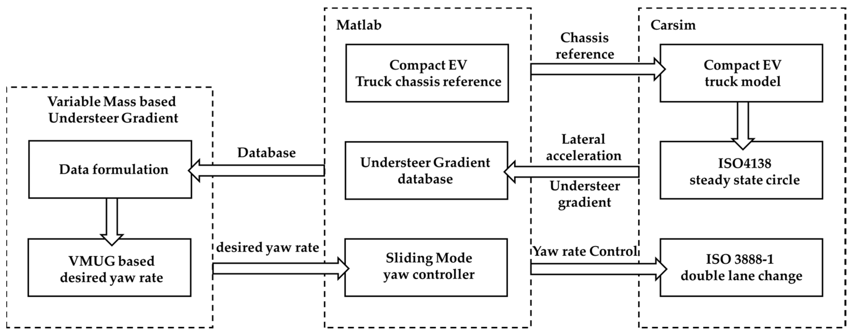
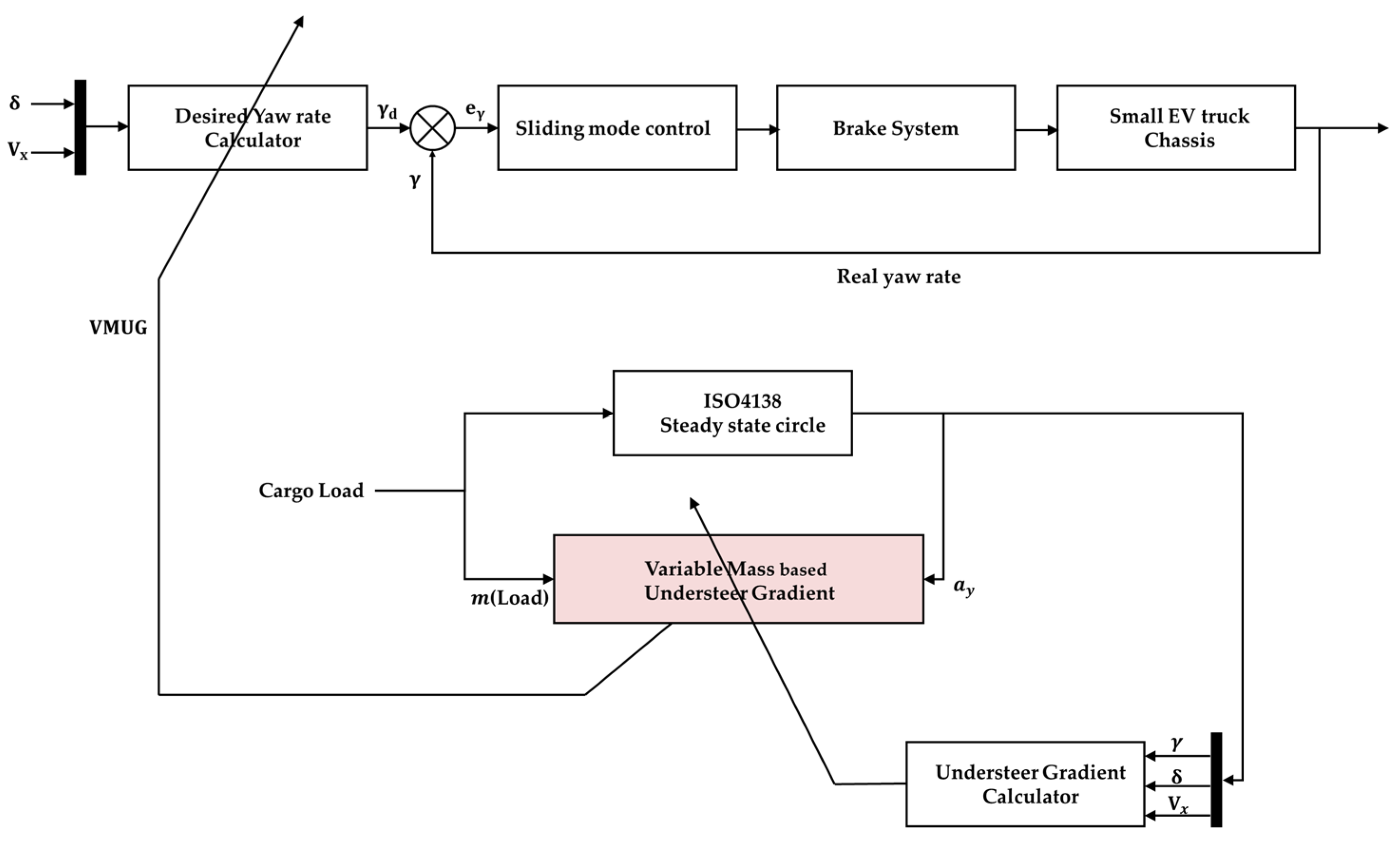
In this study, the problem of cornering stiffness was solved by mathematically formulating the change in the understeer characteristics of an EV truck according to the vehicle cargo weight. A new reference for the yaw rate was designed based on the understeer gradient and the performance was verified through the slip controller. The overall configuration is shown in
Figure 1. First, the existing method of estimating the desired yaw rate is examined, and the appropriate hypotheses in various tests are confirmed through ISO 3888-1 double lane change [
17]. Second, by the ISO 4138 Steady State Circle test [
18], the desired yaw rate is adjusted by formulating a variable mass understeer gradient (VMUG). Third, using the VMUG formula, the movement of the vehicle with heavy loads that cannot be examined by the Steady State Circle Test is investigated. Finally, a sliding mode slip controller that performs slip control according to the tire load is designed, and the performance of the VMUG is verified by comparing with the control of various desired yaw rate references.
2. Dynamic Model
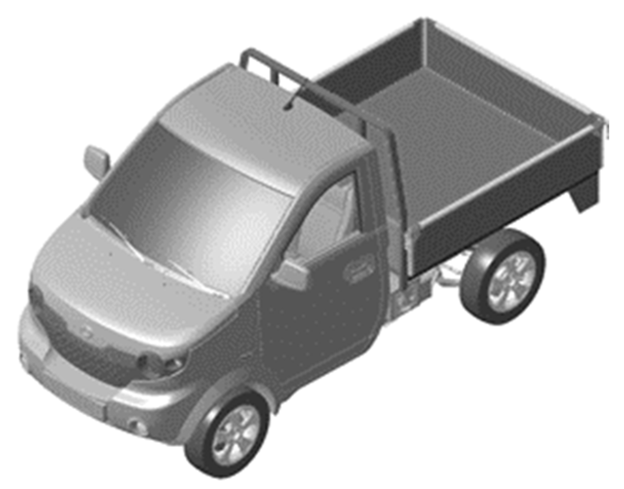
The target vehicle for application is a small truck with front-wheel drive.
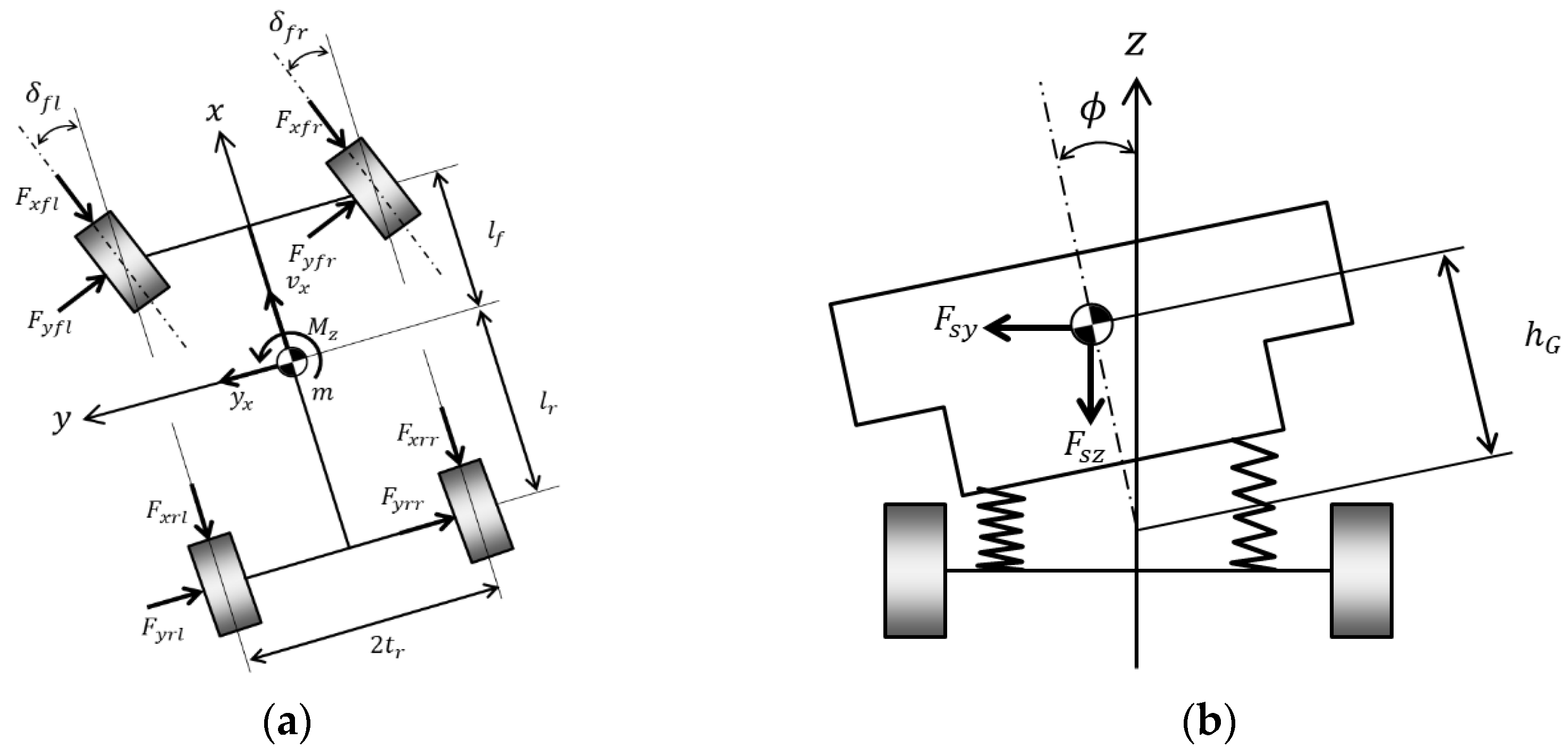
Figure 2 and
Figure 3 and
Table 1 show the modeling and detailed parameter values of the target vehicle for VMUG application.
The 2D motion model of the vehicle can be described using Lagrange’s equation [
19,
20]. The generalized external force
Q related to the generalized coordinate
q can be expressed as follows.
In Lagrange’s equation, the external force generated by the yaw movement can be arranged as a target. The yaw dynamics for yaw control required for the slip model can be expressed as follows, depending on yaw rate and vehicle speed:
Assuming that the slope of the roll axis is small, the kinematic energy
K can be expressed as follows. (The description of each variable used is specified in Nomenclature).
Considering the front-wheel steering and ignoring the rear-wheel steering, the equation of motion for the respective yaw motion can be expressed as below.
The equation of motion for the yaw moment can be expressed as follows by performing a linear approximation to the trigonometric function.
3. Proposed VMUG Strategy for Desired Yaw Rate
In this section, reference is set for control of the desired yaw rate based on the steady states. There are two ways to set the desired yaw rate: a mathematical method and an experimental method [
3]. In the mathematical method, the desired yaw rate can be expressed as the value of the velocity according to the road radius. The steering angle and the steady-state angle under the assumption of steady-state circle driving are given as follows.
By rearranging with reference to the understeer gradient
K and using the lateral acceleration
ay =
V2/
R, the desired yaw rate can be obtained as follows.
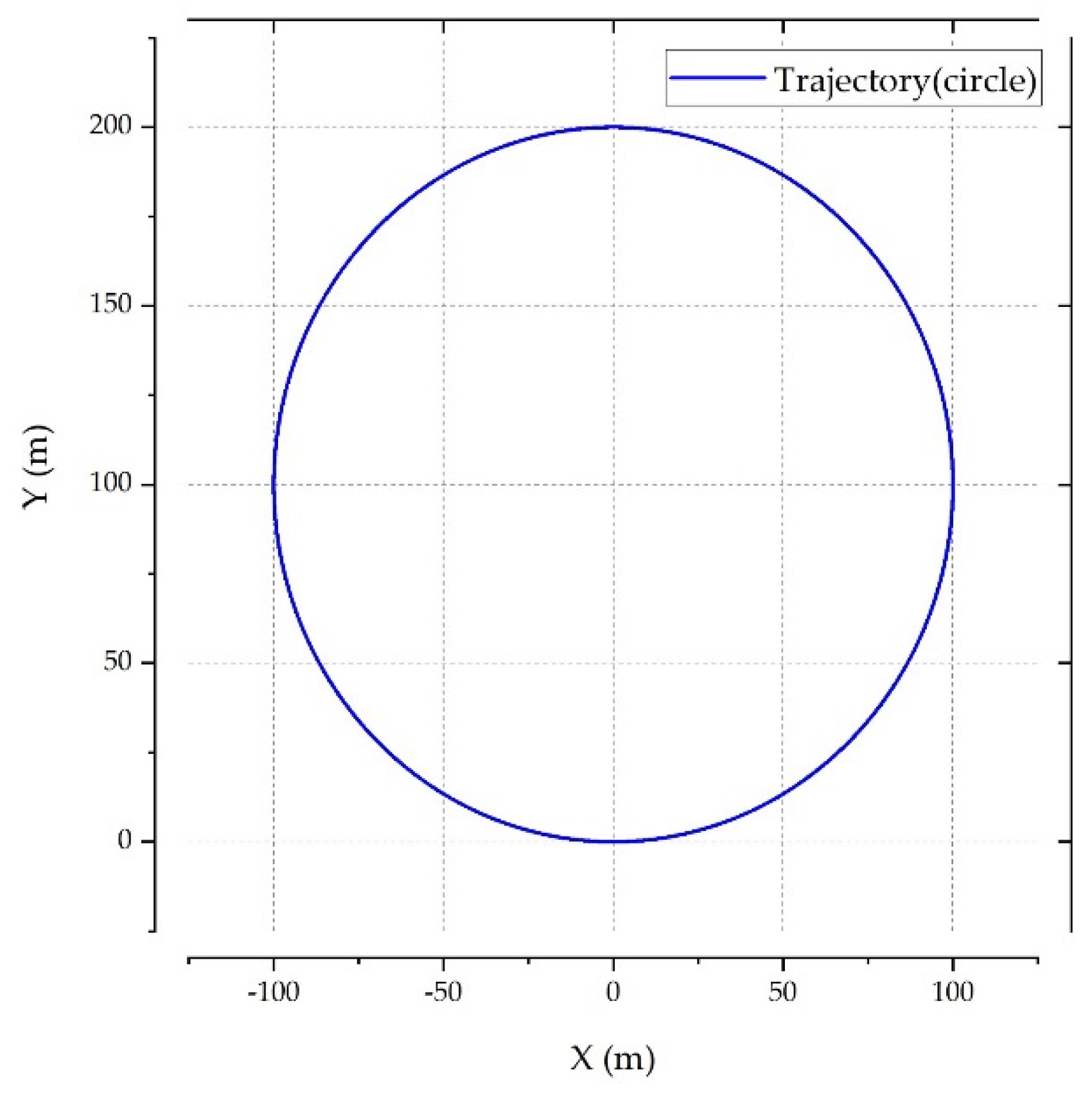
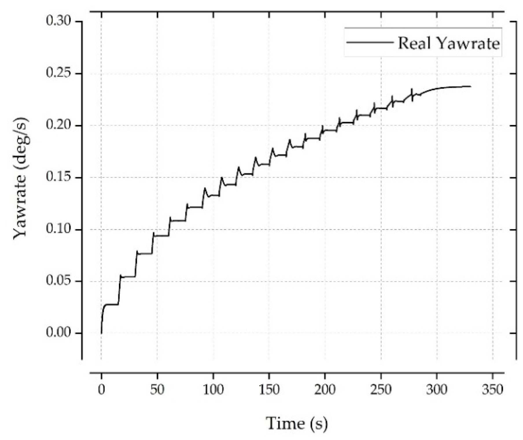
In this study, both the experimental and mathematical methods were implemented to minimize the disadvantages of the conventional desired yaw rate based on mathematical formulation. For the experimental method, the ISO 4138 Steady State Circle test, as shown in
Figure 4, was applied. Within a radius of 100 m, the lateral acceleration was increased from 0 to 0.9 g in steps of 0.3 g, the understeer gradient in steady-state section was formulated, and this was used in the equation of the desired yaw rate. The vehicle was designed as a small truck with a maximum cargo weight of 600 kg. As the value of the understeer gradient changes according to the cargo weight, the desired yaw rate also changes accordingly. The desired yaw rate using constant cornering stiffness and the yaw rate changing according to the applied load are shown in
Figure 5. The yaw rate data can be obtained by increasing the cargo weight from 0 to 600 kg with the center of mass at (315 mm, 2000 mm). The dimension of the cargo is set to 0.516 × 0.816 × 0.816 m, and the mass inertia of the cargo is given in
Table 2.
Furthermore, for control in case of overloading beyond the allowable limit, information on the desired yaw rate at the load is required. However, in the case of 40% overloading, simulation was not possible through the Steady State Circle test. Therefore, by mathematically formulating the understeer gradient that changes depending on the cargo weight, the expected understeer gradient value at overloading is estimated.
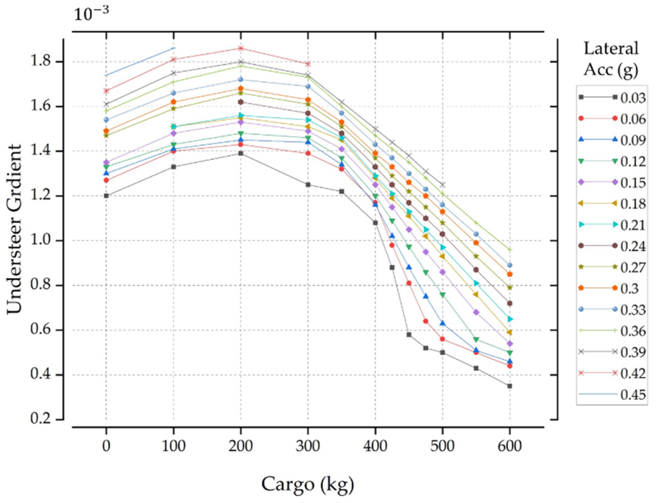
Understeer gradient values according to lateral acceleration and cargo mass are shown in
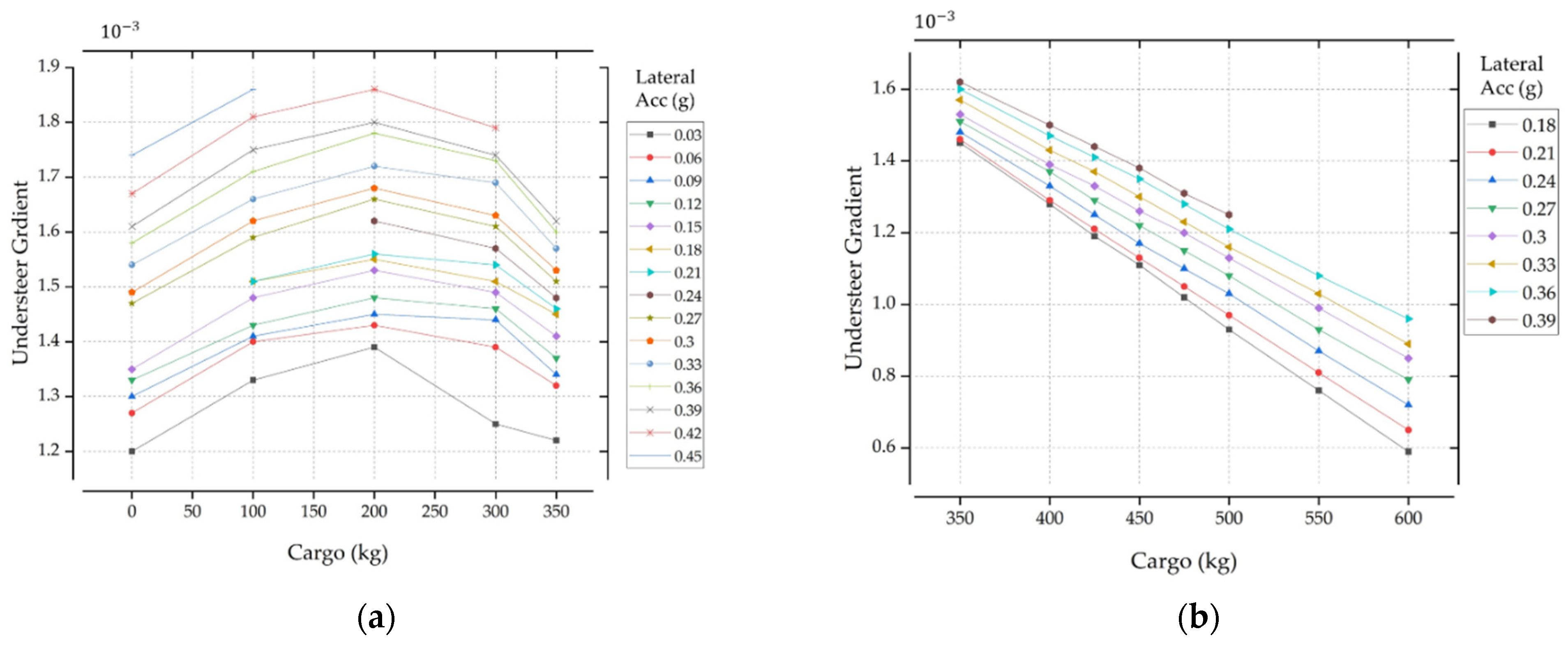
Figure 6. For lateral acceleration of 0.39 g or more, the simulation did not work properly. However, two trends of the understeer gradient could be confirmed. The proposed yaw rate strategy was divided into a linear form section and a quadratic form section through an empirical method for division according to load and lateral acceleration. Each section was formulated by polynomial fitting as shown in
Figure 7.
The section for cargo weight up to 350 kg is in quadratic form, and it is rearranged for lateral acceleration from 0.06 to 0.42 g as follows.
Rearranging the above gives the following:
The section for cargo weight of 350 to 600 kg is in a linear form, and it is rearranged for lateral acceleration from 0.18 to 0.39 g as follows.
The VMUG equation, including cargo weight, can be rearranged and expressed as follows.
4. Analysis of Conventional Desired Yaw Rate Method
At cornering, lateral force and slip angle are generated in the tire, and the cornering stiffness is expressed as the ratio of these two, which is constant up to a certain point. In addition, it also changes depending on the load and the radius of the tire [
20], as well as according to the air pressure set in the vehicle [
16]. The cornering stiffness described above can be calculated only when the slip angle and the lateral force can be empirically obtained. In particular, since the tire slip angles are calculated using an estimator, a controller with high performance and fast reaction speed is required for vehicle slip control. Pacejka et al. proposed a method of calculating cornering stiffness using the Magic formula [
6]. To compare the characteristics of vehicles using the formula, the understeer gradient values used in previous methods were summarized and compared. The nominal understeer gradient values for design purposes can be expressed as the ratio of load
W and the tire’s cornering stiffness
C on each axis.
For a detailed analysis, a comprehensive value considering the nominal understeer gradient, lateral load transfer, camber change, lateral force compliance, roll steer, and steering system compliance steer, is used as follows.
In this study, our aim is to obtain an accurate value of the nominal understeer gradient for comparison using simulations, which requires calculating the cornering stiffness in real time. This can be achieved by rearranging it as follows.
However, when the wheel steer angle θv is close to the steering angle δ due to rapid steering of the vehicle, a notch is generated rendering the control impossible. Therefore, it is necessary to use optimal cornering stiffness, and in a number of studies, this is assumed to be constant. Alternately, a robust controller considering the nonlinearity is designed to respond to changes in cornering stiffness. In this study, the conventional constant cornering stiffness that can accurately indicate the desired yaw rate was used as a reference for comparison with VMUG.
Another method of obtaining cornering stiffness is to use the Magic formula. The understeer gradient simply expressed using the cornering stiffness equation is shown as follows.
The terms
c1 and
c2 depend on the vehicle characteristics. From
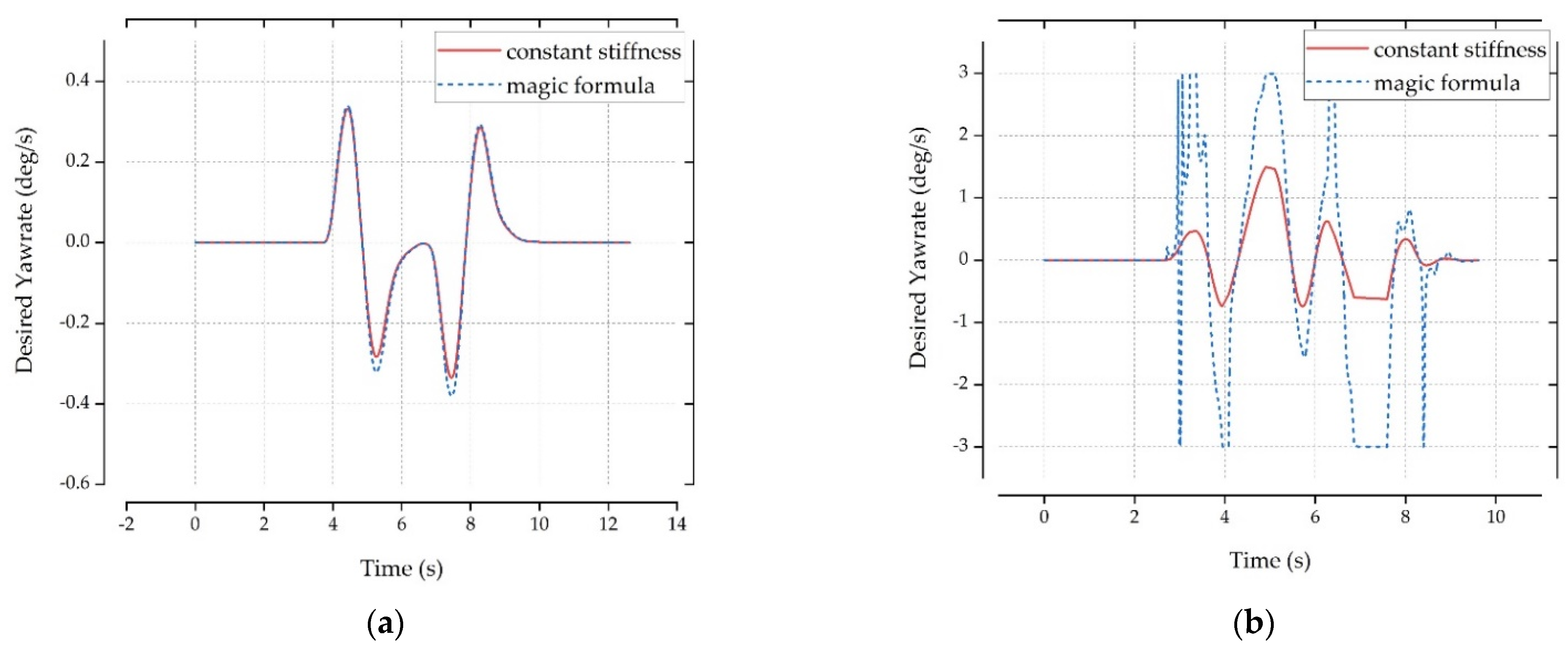
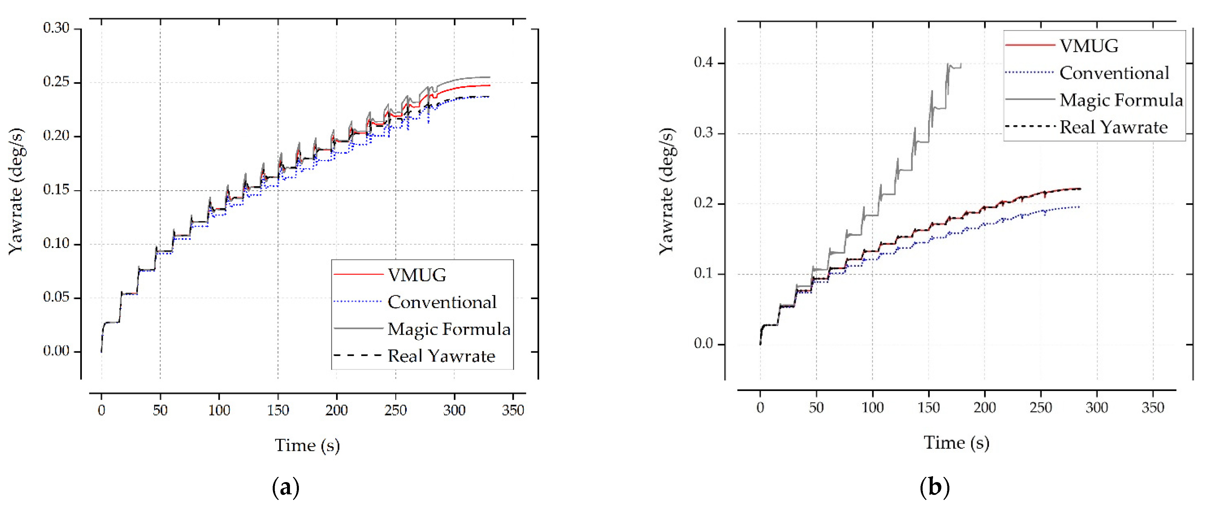
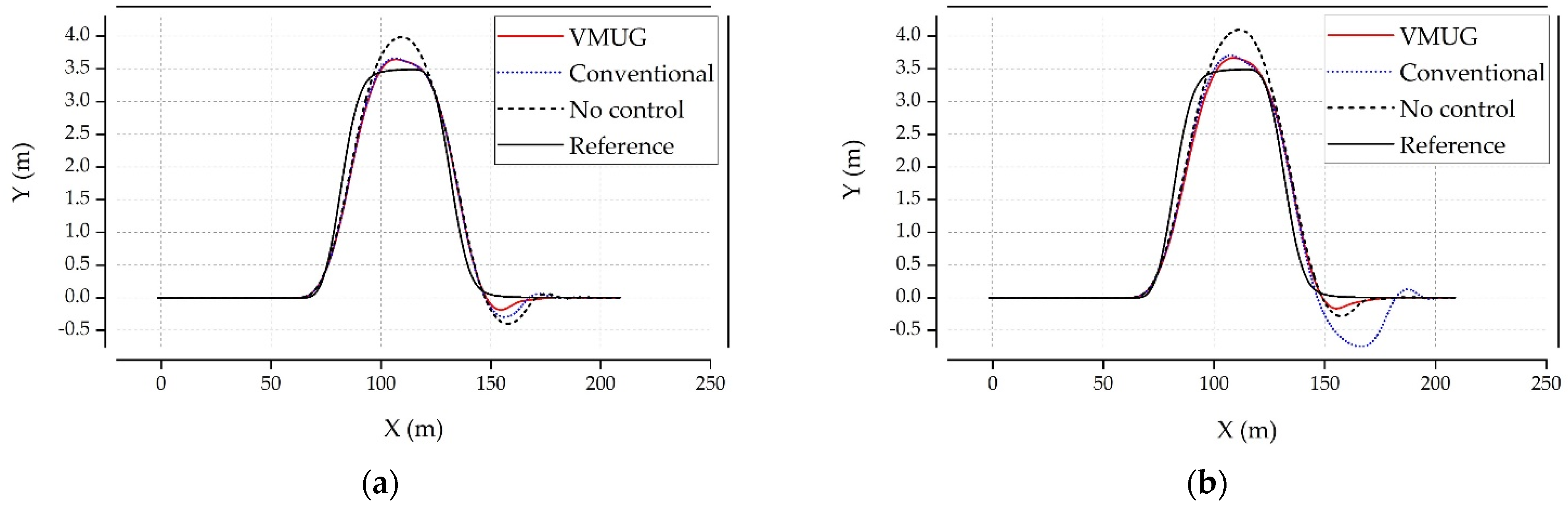
Figure 8, for general road surfaces with a low-speed driving at 60 km/h or less, it can be seen that the desired yaw rate value based on the constant cornering stiffness or Magic formula is obtained without a significant error. For vigorous vehicle movement, setting the accurate desired yaw rate is difficult in practice. In
Figure 8b, it can be seen that a notch occurs for high speed and low friction double lane change with the conventional estimation method, indicating that a proper control is not possible. It can be seen that for dynamic vehicle movement, the control is difficult if an appropriate desired yaw rate is not selected.
When the target vehicle is a truck, the characteristics of the vehicle movement show more dynamic changes, as not only the total weight of the vehicle varies depending on the cargo weight, but the load applied to the center of mass and the vehicle shaft changes as well. Therefore, the cornering stiffness and the understeer gradient of the vehicle vary accordingly, leading to a varying desired yaw rate. This can be critical for the vehicle slip control due to the fast-changing reference. It can be inferred that the selection of an appropriate reference for the design of the slip controller can influence the control. Each desired yaw rate is verified through the controller design in Chapter 6.
5. VMUG Based Sliding Mode Slip Controller Design
To confirm the proposed desired yaw rate, a sliding mode controller, which is a universal robust controller, was designed. The VMUG based desired yaw rate designed in Chapter 3 was used as the control reference. The control block diagram is shown in
Figure 9. The vehicle slip controller controls the brake so that the sum of the longitudinal force and the lateral force does not exceed the maximum allowable friction based on the Kamm’s circle at the turning of the vehicle. The sliding mode plane for applying the brake is expressed as follows.
The derivative value of the sliding mode plane s is rearranged, and the sliding mode surface obtained in the lateral dynamics is substituted. Rearranging for the derivative of yaw rate gives the following:
If the sliding mode plane is applied to (5) for the yaw moment derived in Chapter 2, it is arranged as follows.
The yaw moment when both braking and driving force can be used, such as in the wheel motor, can be summarized as a control formula that uses all four wheels. However, it is simplified as follows because the brake control must be used in the general motor drive method.
When the slip in the vehicle tire occurs, the control method changes due to the reduction of the maximum friction. This is not considered in the current study. In absence of the slip, the driving force and braking force are generated in proportion to the longitudinal force of the tire as follows.
Since the braking force for brake control must be within Kamm’s circle, the maximum braking force can be calculated as follows.
The yaw moment using the sliding mode controller based on the controller formula (25) and the brake yaw moment (27) is obtained as follows.
With the two equations, under the assumption that the ratio of the lateral force and the longitudinal force is maintained linear, if the braking force of the front-left wheel
for VDC is calculated, it can be reorganized and expressed as follows.
6. VMUG Based Yaw Rate Verification
The verification of VMUG was carried out in two ways: by the non-control yaw rate calculation method and by comparing performance through the sliding mode slip controller.
The simulation environment adopted in this study was MATLAB Simulink and Carsim. In Carsim, the characteristics of the hardware chassis of the EV truck were applied, and VMUG and SMC were configured in MATLAB.
6.1. Verification by Non Control Simulation
Testing the VMUG equation through the 100 m steady-state circle test confirmed the following as shown in
Figure 10. The VMUG based method was compared to the conventional stiffness-based method such as the Constant stiffness and the Magic formula method. For a full load of 600 kg, the VMUG based method clearly shows accuracy compared to the other methods.
6.2. Verification by Sliding Mode Slip Controller
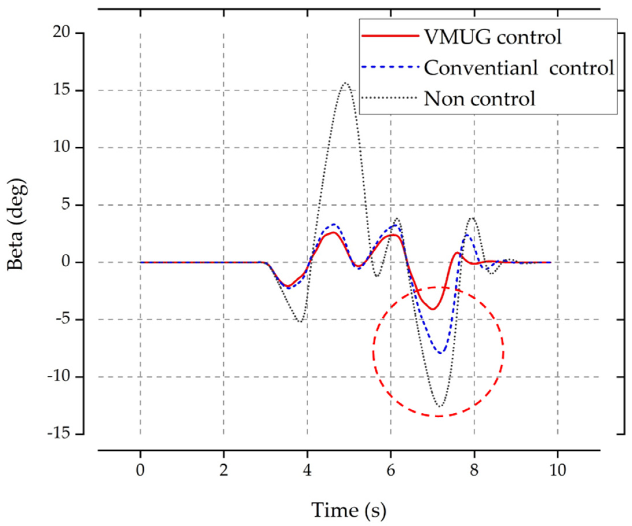
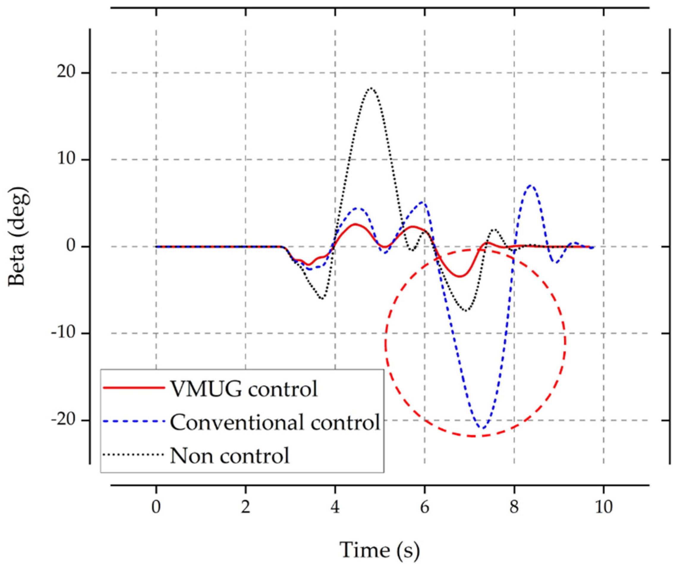
The result of the slip angle in the double lane change test with full loading of 600 kg and overloading of 1000 kg under the conditions of 80 km/h speed and μ = 0.5 is shown in
Figure 11 and
Figure 12. In the SMC slip control using the conventional method of constant cornering stiffness, a large slip angle is formed while returning from the second lane, rendering the control impossible. On the other hand, VMUG-based SMC slip control shows a significantly smaller slip angle. The result shows that VMUG presents an appropriate reference for robust control of vehicle stability even in the overloading condition of 40% or more.
Figure 13 shows the route in the double lane change situation. Both the VMUG control and the conventional control properly follow the reference at full load. However, the conventional control shows a large path deviation corresponding to 0.75 m for the case of overload. The VMUG control deviated 0.16 m even under overload, confirming 78.7% improvement.
7. Conclusions
In this study, we investigated the change of desired yaw rate according to the cargo weight of a small EV truck with front-wheel drive. It was confirmed that the performance of the proposed yaw rate strategy was superior for both normal loading and overloading. As the weight of the load increased, it was confirmed that the performance of the proposed method in the 80 km/h DLC test improved to a maximum of about 17 degrees based on the slip angle of the chassis. Therefore, this study opens the prospect of application of the VMUG to compact EV trucks in the future, while ensuring stability even for overloading scenarios. It is expected that further research on VMUG has the potential of its application in general purpose vehicles other than the compact EV truck considered in this paper.
Author Contributions
Conceptualization, methodology, H.-W.K. and H.-R.C.; software, validation, formal analysis, investigation, resources, data curation, writing, visualization, H.-W.K.; supervision, funding acquisition, project administration, H.-R.C. All authors have read and agreed to the published version of the manuscript.
Funding
This research was funded by the support of the Korea Institute of Industrials Technology as “Development of Core Technologies for a Working Partner Robot in the Manufacturing Field” (KITECH EO-21-0004).
Institutional Review Board Statement
Not applicable.
Informed Consent Statement
Not applicable.
Data Availability Statement
Not applicable.
Acknowledgments
This research was conducted using equipment from KITECH (Gwangju, Korea).
Conflicts of Interest
The authors declare no conflict of interest.
Nomenclature
| lateral acceleration of vehicle |
| longitudinal force of tire |
| lateral force of tire |
| lateral force of tire |
| vertical force of tire |
| distance of the mass center from axles |
| roll moment of inertia of the vehicle |
| yaw moment of inertia of the vehicle |
| understeer gradient |
| kinematic energy |
| distance from mass center to front and rear axles |
| mass of vehicle |
| brake moment |
| yaw moment |
| radius of cornering circle |
| front and rear width of vehicle |
| longitudinal velocity of vehicle |
| lateral velocity of vehicle |
| tire side slip angle |
| chassis slip angle |
| yaw rate |
| desired yaw rate |
| roll angle |
| friction coefficient of road |
References
- Ahangarnejad, A.H.; Radmehr, A.; Ahmadian, M. A review of vehicle active safety control methods: From antilock brakes to semiautonomy. J. Vib. Control 2021, 27, 1683–1712. [Google Scholar] [CrossRef]
- Indu, K.; Kumar, M.A. Electric Vehicle Control and Driving Safety Systems: A Review. IETE J. Res. 2020, 26, 1–17. [Google Scholar] [CrossRef]
- Gillespie, T.D. Fundamentals of Vehicle Dynamics; SAE International: Warrendale, PA, USA, 1992. [Google Scholar]
- Shinho, M.; Nagai, M. Yaw-moment control of electric vehicle for improving handling and stability. JSAE Rev. 2001, 22, 473–480. [Google Scholar] [CrossRef]
- Chen, Y.; Hedrick, J.K.; Guo, K. A novel direct yaw moment controller for in-wheel motor electric vehicles. Vehicle Syst.Dyn. 2013, 51, 925–942. [Google Scholar] [CrossRef]
- Pacejka, H.B. Tyre and Vehicle Dynamics, 3rd ed.; Elsevier: Oxford, UK, 2012; pp. 87–147. [Google Scholar]
- Ren, B.; Chen, H.; Zhao, H. MPC-based yaw stability control in in-wheel-motored EV via active front steering and motor torque distribution. Mechatronics 2016, 38, 103–114. [Google Scholar] [CrossRef]
- Wasim, M.; Kashif, A.; Awan, A.U. H-infinity control via scenario optimization for handling and stabilizing vehicle using AFS control. In Proceedings of the 2016 International Conference on Computing, Electronic and Electrical Engineering (ICE Cube), Quetta, Pakistan, 11–12 April 2016; pp. 307–312. [Google Scholar]
- Saikia, A.; Mahanta, C. Vehicle stability enhancement using sliding mode based active front steering and direct yaw moment control. In Proceedings of the 2017 Indian Control Conference (ICC), Guwahati, India, 4–6 January 2017; pp. 378–384. [Google Scholar]
- Wang, Z.; Montanaro, U.; Fallah, S. A gain scheduled robust linear quadratic regulator for vehicle direct yaw moment Control. Mechatronics 2018, 51, 31–45. [Google Scholar] [CrossRef]
- Zhao, W.; Qin, X.; Wang, C. Yaw and lateral stability control for four-wheel steer-by-wire system. IEEE/ASME Trans. Mechatron. 2018, 23, 2628–2637. [Google Scholar] [CrossRef]
- Termous, H.; Shraim, H.; Talj, R. Coordinated control strategies for active steering, differential braking and active suspension for vehicle stability, handling and safety improvement. Veh. Syst. Dyn. 2019, 57, 1494–1529. [Google Scholar] [CrossRef]
- Ma, X.; Wong, P.K.; Zhao, J.; Xie, Z. Cornering stability control for vehicles with active front steering system using T-S fuzzy based sliding mode control strategy. Mech. Syst. Signal Process. 2019, 125, 347–364. [Google Scholar] [CrossRef]
- Cho, W.; Yoon, J.; Kim, J.; Hur, J. An investigation into unified chassis control scheme for optimised vehicle stability and manoeuvrability. Veh. Syst. Dyn. 2008, 46, 87–105. [Google Scholar] [CrossRef]
- Seo, M.; Yoo, C.; Park, S.; Nam, K. Development of Wheel Pressure Control Algorithm for Electronic Stability Control (ESC) System of Commercial Trucks. Sensors 2018, 18, 2317. [Google Scholar] [CrossRef] [PubMed] [Green Version]
- Singh, K.B. Vehicle Sideslip Angle Estimation Based on Tire Model Adaptation. Electronics 2019, 8, 199. [Google Scholar] [CrossRef] [Green Version]
- ISO 3888-1:2018. Passenger Cars—Test Track for a Severe Lane-Change Manoeuvre—Part 1: Double Lane-Change; ISO: Geneva, Switzerland, 2018. [Google Scholar]
- ISO 4138:2012. Passenger Cars—Steady-State Circular Driving Behaviour—Open-Loop Test Methods; ISO: Geneva, Switzerland, 2012. [Google Scholar]
- Naraghi, M.; Roshanbin, A.; Tavasoli, A. Vehicle stability enhancement—An adaptive optimal approach to the distribution of tyre forces. Proc. Inst. Mech. Eng. Part D J. Automob. Eng. 2010, 224, 443–453. [Google Scholar] [CrossRef]
- Vorotovic, G.S.; Rakicevic, B.B.; Mitic, S.R.; Stamenkovic, D.D. Determination of Cornering Stiffness through Integration of A Mathematical Model and Real Vehicle Exploitation Parameters. FME Trans. 2013, 41, 66–71. [Google Scholar]
| Publisher’s Note: MDPI stays neutral with regard to jurisdictional claims in published maps and institutional affiliations. |
© 2021 by the authors. Licensee MDPI, Basel, Switzerland. This article is an open access article distributed under the terms and conditions of the Creative Commons Attribution (CC BY) license (https://creativecommons.org/licenses/by/4.0/).


