1. Introduction
With the rapid development of the national economy, the demand for electricity in modern society is increasing. Therefore, the power industry has put forward higher and higher requirements for the safe, reliable and stable operation of power systems. Any error in the power system may lead to the occurrence of power accidents, which endangers the stability and routine operation of the whole power system [
1]. The operating status of the equipment in a substation is judged based on each measurement datum. In order to ensure the safe and stable operation of a substation, the meters must be inspected regularly and repaired in time. However, the traditional inspection method is usually manual inspection, which brings problems of low efficiency, low precision and increased time consuming. In addition, the staff’s vision, attitude and other personal factors will also affect the reading results. In some inclement weather, when real-time readings cannot be performed manually, it may affect the operation of the entire substation [
2,
3]. The further development of computer technology and the improvement of the smart grid make the intelligentization of substations a future development trend. At present, more and more substations use inspection robots for inspections, instead of manual inspections, which suffered from heavy and dangerous tasks. The inspection robot is equipped with visible light cameras, infrared thermal imaging cameras and other devices to realize the intelligent identification and linkage of the facilities in the station. At the same time, multiple inspection modes are adopted to realize 7*24 h unmanned inspections [
4]. It can also achieve real-time data collection, data transmission and intelligent early warnings, which ensure the safe and stable operation of the power grid [
5]. Therefore, robot inspections in substations will surely replace manual inspections. Dial gauges with a simple structure, good cold-proof and waterproof performance are utilized in the electromagnetic interference environment of the substation. In addition, the barometers and thermometers used in substations commonly are suitable for mechanical pointer structures. A large number of dial gauges are used in substations, and they will be irreplaceable for a long time. The realization of the automatic reading of pointer instruments is a necessary condition for intelligent substations. Therefore, it has broad research prospects.
Many automatic reading algorithms of dial gauges based on machine vision have been proposed. Guan Yudong et al. [
6] detected the position of the industrial resistance meter by using the image difference after image preprocessing. Zhijuan Yang et al. [
7] proposed a method of meter identification based on the area cumulative histogram. The position of the meter is obtained through the calculation of the histogram. This method is not to obtain the instrument directly from the image, as there will be errors in the conversion process, causing low reading accuracy. Yang Jian et al. [
8] used a cloud based visual attention objects detection method to extract the interest pointer area, and then used the projection method to obtain the pointer deflection direction and angle for calculation. It reduced the effect of illumination but increased the amount of calculation, which leads to low efficiency. Zheng Chao et al. proposed a novel reading method in [
9], which can identify meter images under different brightness intensity and camera angles, and has good robustness. In order to prevent the collected meter from being deformed, Ma Yifan et al. [
10] presented an eight chain code shape to represent the pixel image shape, and used a binarization threshold determination method based on the symmetry degree to solve the pointer interference. Although the threshold-based segmentation method is efficient, it is easily affected by light. A reading method of analog multimeters was proposed by Chen Yung-Sheng et al. in [
11], which mainly depends on information from the arrow on the function selector and the pointer on the instrument meter. The schemes of edge-based geometric matching and pyramidal gradient matching are used to detect the regions of interest. The mapping relationship between the function selector and the selector arrow, as well as that between the instrument meter and the pointer, are built and formulated to finally read the A-meter. This method is robust, but it can only be applied to specific instrument characteristics. Bao Haojing et al. [
12] applied the multiple dial gauge measurement method based on the inverse perspective mapping. The inverse perspective method was used to eliminate the influence of the angle on the readings. The visual inspection method was used to measure the processed image and obtain the meter reading. This method has high reading accuracy under the system which can control the brightness, but it has poor robustness in industrial fields where the measurement environment is complicated.
In recent years, deep learning has been applied in this field and provided excellent results. Hung Mao-Hsiung et al. [
13] used a method of using frame training and testing to detect pointers. The gray level sub-sampling along the tick marks generates a 1D signal and local maximums on the 1D signal that are used to calculate the meter reading. Cai Weidong et al. proposed a new virtual sample generation technology in [
14]. It solved the problem of generating a large number of images from a small number of real samples to train the recognition, and then obtained readings by analyzing the key information of the instrument images. He Peilin et al. [
15] improved the Mask-RCNN network and used PrRoIPooling instead of RoiAlign to improve the accuracy of segmentation. The improved Mask-RCNN was introduced to divide the dial and pointer area; then, fitted the pointer and judged the meter type at the same time; and, finally, used the angle method to calculate the reading. Li Zhu et al. [
16] applied a novel algorithm for the adaptive detection of different dial gauges, which solved the problems of light affecting the accuracy and robustness of the shooting angle. It introduced deep learning technology to detect the scale value and text on the meter. After obtaining the text box, the center coordinates in the text box were adopted to correct the image to eliminate the influence of the shooting angle on the reading. A meter classification method based on Faster R-CNN was proposed by Xin Zhang et al. in [
17]. Image processing of the positioned dial gauge image was operated to calculate a more accurate pointer reading. Algorithms based on deep learning have a high accuracy in detecting instruments, but they require a lot of time to train in the early stage. This method is not universally applicable to workplaces such as substations that require real-time detection and real-time warning.
In summary, the above research is aimed at a single instrument problem and does not involve the problems of uneven illumination, complex background and damping fluid interference at the same time. Pointer instrument detection is mainly divided into the following three steps: instrument detection, scale segment positioning and pointer fitting. When performing these steps, it will be affected by the light, the complicated background of the dial and the damping fluid. In order to solve the above problems, this paper proposes an automatic reading algorithm for dial gauges based on coordinate positioning.
In general, the automatic reading algorithm based on coordinate positioning comprises two parts. One part is the coordinate extraction. This mainly includes the coordinate of the center and pointer of the dial. The other is the automatic recognition of the reading. The final reading result is obtained according to the relative position of the point on the dial. The automatic reading algorithm proposed in this paper falls into the following four steps:
- (1)
The enhancement of the image: The image preprocess step by using the MSRCR algorithm to reduce the influence from the brightness.
- (2)
The location of the center: First, in the entire image, all the straight lines can be determined using an LSD straight line algorithm. Then, the arc-support segment can be selected from these straight lines. Finally, according to the selected arc-support segments, the centers and the radius of the circle dial can be obtained.
- (3)
The location of the pointer: The pointer is first extracted using the pointer-free template. By using a thinning algorithm and producing the concentric circle of the center, the position of the pointer in the dial is determined.
- (4)
The automatic reading: The indicating value is calculated according to the relative pointer position in the dial automatically.
2. Automatic Reading Algorithm of Dial Gauge Based on Coordinate Positioning
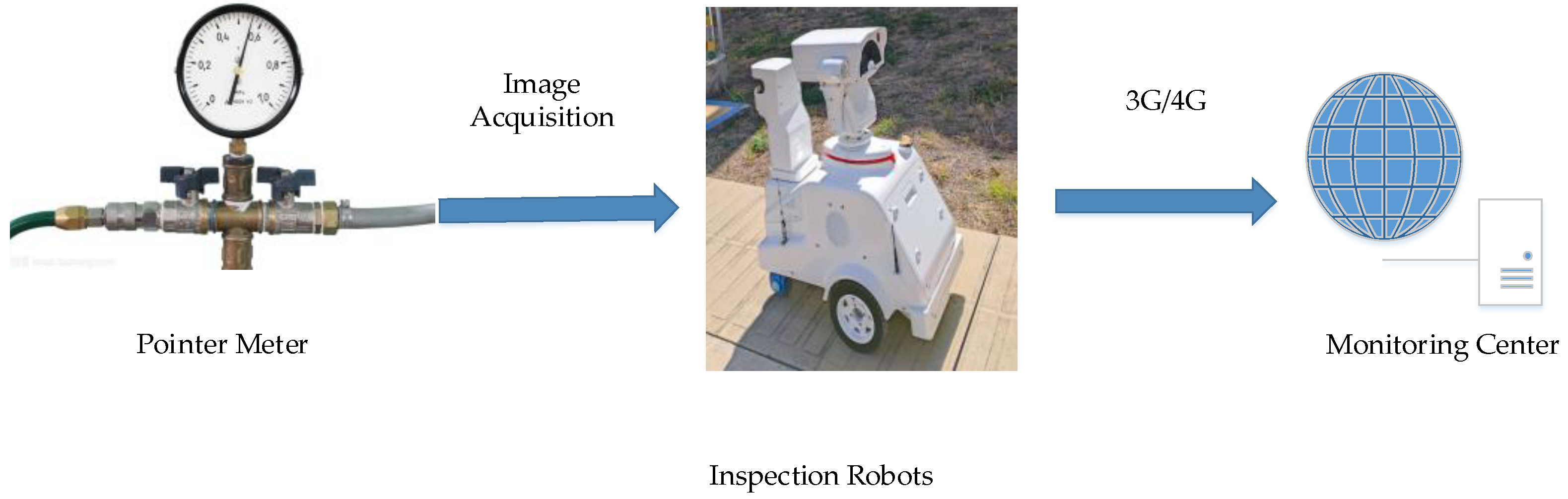
The automatic reading process of the dial gauge on the inspection robot is shown in
Figure 1. An image of the instrument is taken by the visible light camera on the inspection robot. Then, the reading is identified according to the automatic reading system, and the 3G or 4G network is used to transmit the reading result to the background monitoring center.
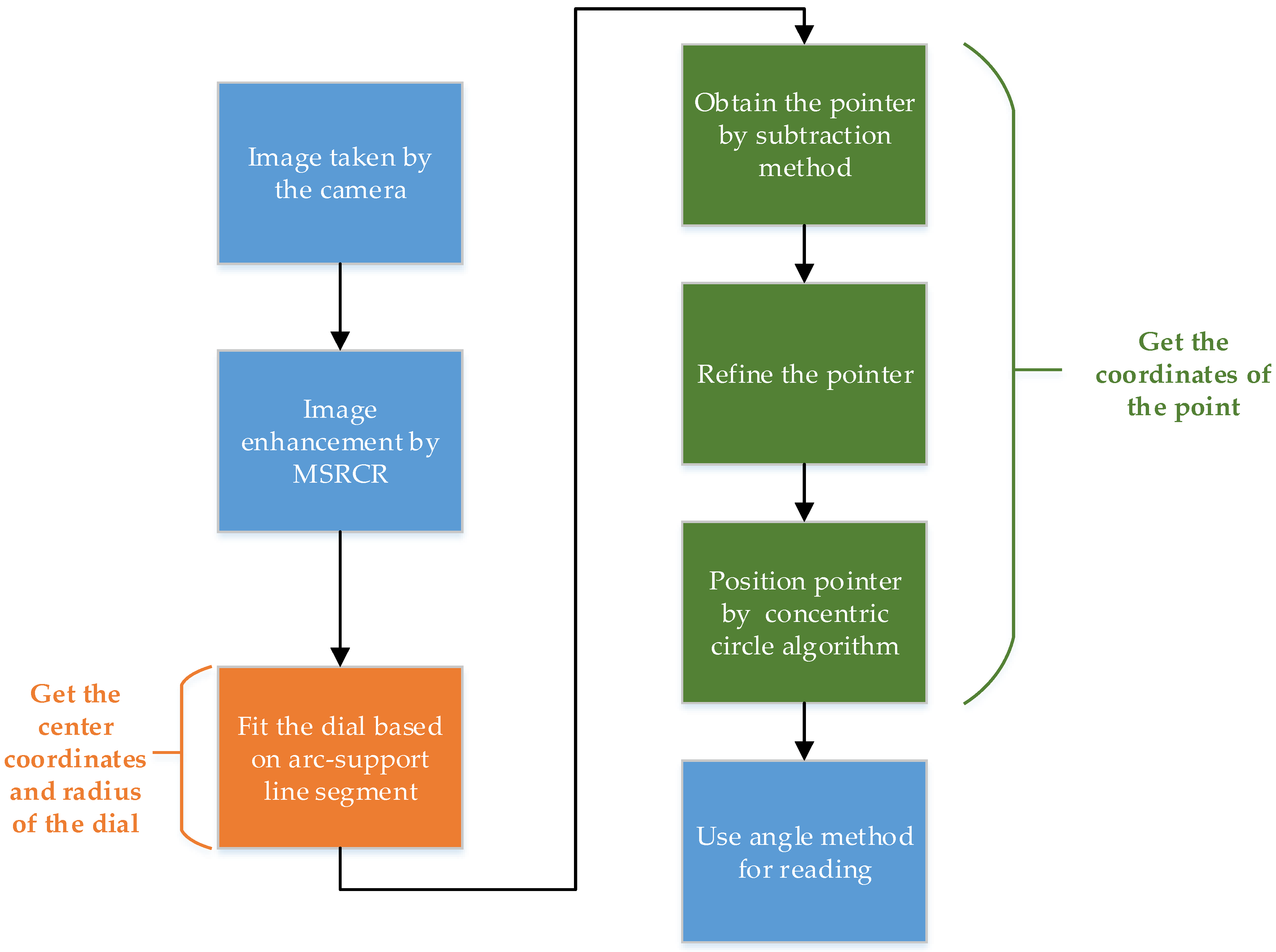
In this section, the steps of the proposed method for the automatic reading of dial gauges in substations are described in detail. The procedure for the operating steps is illustrated in the flowchart shown in
Figure 2. First, apply the MSRCR algorithm to enhance the image, improve the image contrast and ensure that the subsequent algorithm processing is not affected by light. Second, use circle detection based on arc-support line segments to detect the disc, and accurately locate the center and radius of the circle. Next, refine the pointer extracted using the subtraction method, making a circle with the center of the circle and an appropriate radius. Then, the coordinates of a point on the pointer can be obtained from the intersection of the circle and the pointer. Finally, calculate the reading based on the relative position of the pointer on the dial.
2.1. Image Enhancement
Many factors influence the level of brightness, such as weather, time, indoor or outdoor, etc. For example, the brightness level will be particularly strong when the weather changes. It is an effective method to use the MSRCR to enhance color images that lack brightness [
18]. The theoretical underpinning of the MSRCR algorithm is that the color of the object is not affected by the non-uniformity of illumination. The main idea of the MSRCR algorithm is to calculate the brightness image from the original image effectively. Therefore, the MSRCR algorithm has the characteristics of color constancy. Since the MSRCR algorithm is based on the single-scale Retinex (SSR) and the multi-scale Retinex (MSR), SSR and MSR will be introduced first. The single-scale Retinex (SSR) algorithm is as follows [
19,
20]:
where
Ri(x,y) is the Retinex output,
Ii(
x,
y) is the distribution in the
ith spectral band, “*” indicates the convolution operation and where
F(
x,
y) is the following surround function:
where
c is the Gaussian surround space constant,
r2 = x2 + y2, and
K satisfies Equation (3), as follows:
Multi-scale Retinex (MSR) is adopted for Gaussian filtering on an image at different scales, and then a weighted average of the filtering results is performed to obtain the output image. The MSR is defined as follows:
where
n is the number of scale parameters; if
n = 1, it is SSR, which is the weight of the
nth scale.
The standardized scaling function of MSR is defined as follows:
The SSR and MSR algorithms may result in excessive noise in the image, distorting the color of the local details of the image which may fail to show the true color of the object. Therefore, on the basis of MSR, MSRCR introduces a color restoration factor,
C, to compensate for the defect of color distortion caused by the contrast enhancement of the local area of the image, which improve the robustness of the algorithm [
21], as follows:
where
C is the gain constant and
is an adjustment factor.
Finally, by using the Equations (1), (4) and (6), the equation of MSRCE can be written as follows:
where
G is
a gain and
b is an offset coefficient, which are used to display the final image well on the screen. Some basic parameters of MSRCR are shown in
Table 1.
2.2. Center Positioning Based on Arc-Support Line Segment
At present, the detection methods of a circle mainly contain Hough Circle Transform (CHT), Random Sample Consensus (RANSAC) and line segment method. CHT is first proposed, but it is inefficient and occupies a large amount of memory. Additionally, it is sensitive to noise. RANSAC is much more time/costs effective than CHT, at the same time, it has unnecessary calculations that may lead to false detection. A line segment detector with a false detection control (LSD) is a typical representative of the line segment method. It fits the approximate curve using a straight line, but there will be a large number of useless line segments during the detection process, which would result in a long calculation process [
22].
2.2.1. Circle Detection
To solve these problems, this paper proposes a circle detection method based on arc-support line segments to extract the center and radius. First, obtain straight lines from the image by using the LSD straight line detection algorithm, and then extract the centers and radius of the circle that was determined by the arc-support line segment. Finally, verify the fitting of the circle through the least square method.
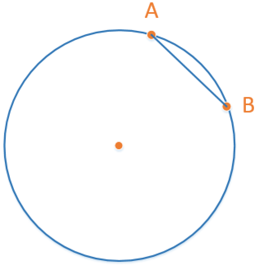
Let us introduce the definition of the arc-support line segment first. Assuming an arc on a circle, the end points are A and B, respectively. Therefore, the straight-line segment AB is the arc supporting line segment. The arc-support line segment is shown in
Figure 3.
Due to the randomness of the line segment pairing, it is necessary to judge whether the line segment pair comes from different circles according to the directionality of the arc-support line segment [
23].
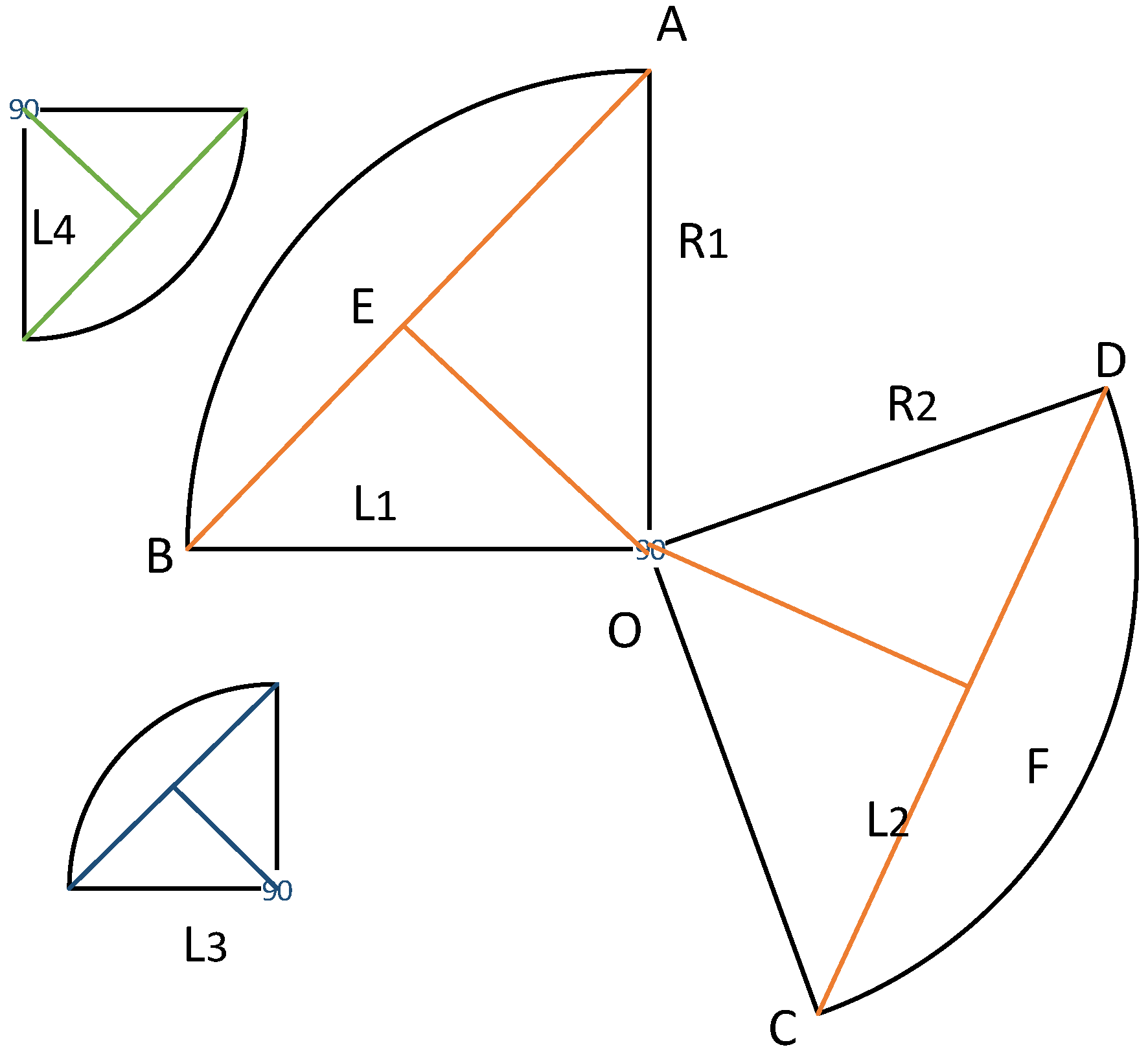
Figure 4 shows the area range of a pair of arc-support line segments. It is obvious that {L1, L3} and {L1, L4} belong to different circles. As shown in
Figure 4, although L3 is in the reasonable area of L1, L1 is not in the area of L3; therefore, it cannot be paired. Only L1 and L2 can be paired within a reasonable area of each other [
24].
Therefore, we have the following:
where the
is the normalized arc-support direction vector of
Li (
i = 1 or 2).
is distance threshold.
The intersection of the vertical bisector of the line segment
L1,
L2 is detected as the center of the circle
O. Assume that
R1 and
R2 are the distances from
O to the pair of line segments {
L1,
L2}, respectively. If the radial distance tolerance
is satisfied, the radius
R is the average value of
R1,
R2. Therefore, we have the following:
After the above calculations, a series of center O and radius R can be obtained, that is, the detection of the initial circle is complete.
2.2.2. Circle Fitting and Verification
In fact, after the initial circles are detected, the initial circles need to be screened so as to remove the repeated circles according to the non-maximum value suppression by the mean shift clustering. Then, we use the least square method to fit the circle. It establishes the best function to find the best result. Finally, verify circle detection results according to the number of edge pixels and the degree of completion of the circle. The number of edge pixels is related to the radius of the circle; therefore, the ratio threshold Tni is used, and the completeness of the circle is Tac.
The center of the dial detection algorithm is as follows:
| 1: Use an LSD line detection algorithm to obtain a series of lines; |
| 2: Judge whether the straight line belongs to the arc-support line segment on the circle using formula (8); |
| 3: Pair the two arc-support line segments to determine the centers and radii of the circles; |
| 4: Use non-maximum value suppression to remove the repeated circles; |
| 5: Use the least square method to fit the remaining circles; |
| 6: Verify the circles. |
2.3. Pointer Positioning
Due to the complex background of the dial, the direct extraction of the pointer will produce a lot of errors; therefore, this article uses the subtraction method to obtain the meter pointer. The specific method is based on the formula 10.
Given the original image
G(
x,
y) and the pointer-free template image
Y(
x,
y), the pointer image can be written as follows:
where
T0 is the threshold value.
In a fixed-point inspection, the size of the dashboard in the image obtained each time remains unchanged. The thinning algorithm is applied to refine the coarse shape of the pointer into a fine pixel shape. Then, the circle is drawn with the circle point and the adaptive radius in experience. The result of the pointer positioning is obtained by the intersection points of the circle and the refined pointer. This method can remove the interference caused by the incomplete pointer extraction, position the pointer more accurately and facilitate the subsequent readings method.
A summarization of the proposed pointer positioning algorithm operating steps is as follows:
| 1: Make a pointer-free template image based on the original image; |
| 2: Extract a pointer using the two images; |
| 3: Use the thinning algorithm to process the pointer; |
| 4: Use the radius algorithm to locate a point on the pointer. |
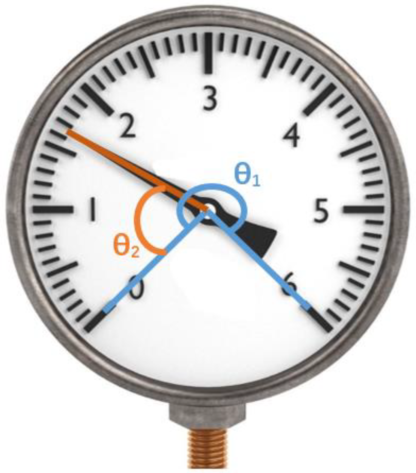
2.4. Reading and Recognition
After the above three subsections, the coordinates of the center of the dial and the coordinates of a pointer on the pointer can be obtained. Then, the angle method is used to obtain the readings of dial.
Figure 5 shows the principle of the angle method. Given that the dial range is ω, which is input by the technician before, the angle between the zero-scale line and the end scale line is
θ1 and the angle between the scale and the pointer line is
θ2, the dial reading can be obtained using the following formula (11):
3. Results and Discussion
To verify the effectiveness of the proposed approach under the influence of light and the complex background of the dial, a series of pressure gauges with damping fluid with a size of 480*480 were selected for the experiment, including MSRCR image enhancement, meter center extraction, pointer positioning and recognition reading experiments. The hardware configuration of the computer used in this experiment is Intel i5-5200U and 2.7 GHz. The programming environment is the Microsoft Visual Studio 2015, using C++ language for programming.
Table 2 lists the primary parameters of the camera in the inspection robot.
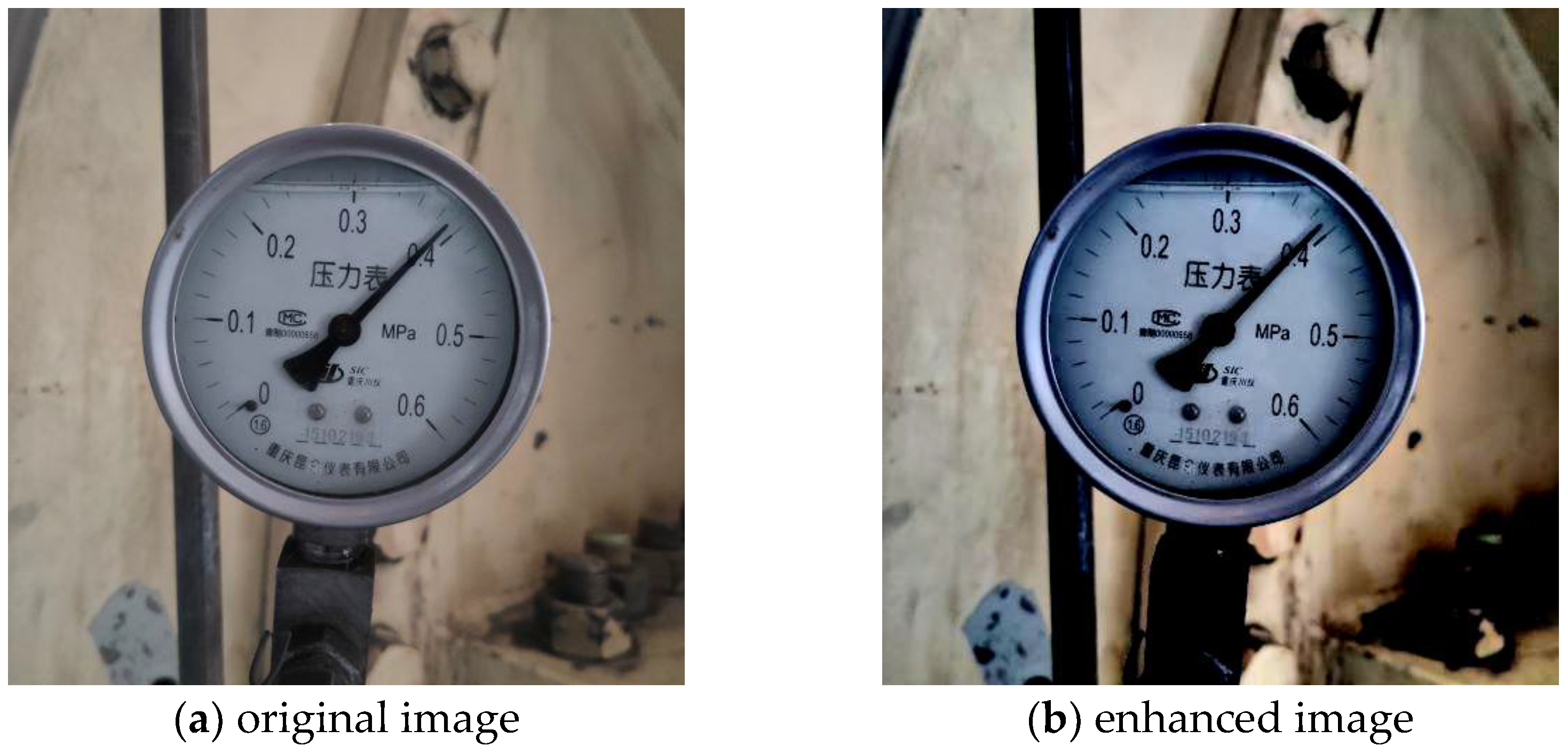
Figure 6 shows the experimental results of each step.
Figure 6a is the original pointer gauge image. From
Figure 6a, it can be seen that the contrast of the image taken under natural light is not high, especially the blurred pointer of the scale line leads to a position inaccurately. For the experiment of center extraction and pointer positioning, the numbers and words in the dial interfere with the next detection. Therefore, this paper proposed a recognition reading algorithm based on coordinate positioning. Firstly, the MSRCR algorithm was used to reduce the influence of light and improve the contrast of the scale line. Then, the center and pointer were directly extracted based on the image information, which greatly reduced the influence of other useless information in the background.
Figure 6b is an enhanced image of MSRCR. It can be clearly found that the scale line is clearer, which is beneficial to the next pointer extraction experiment.
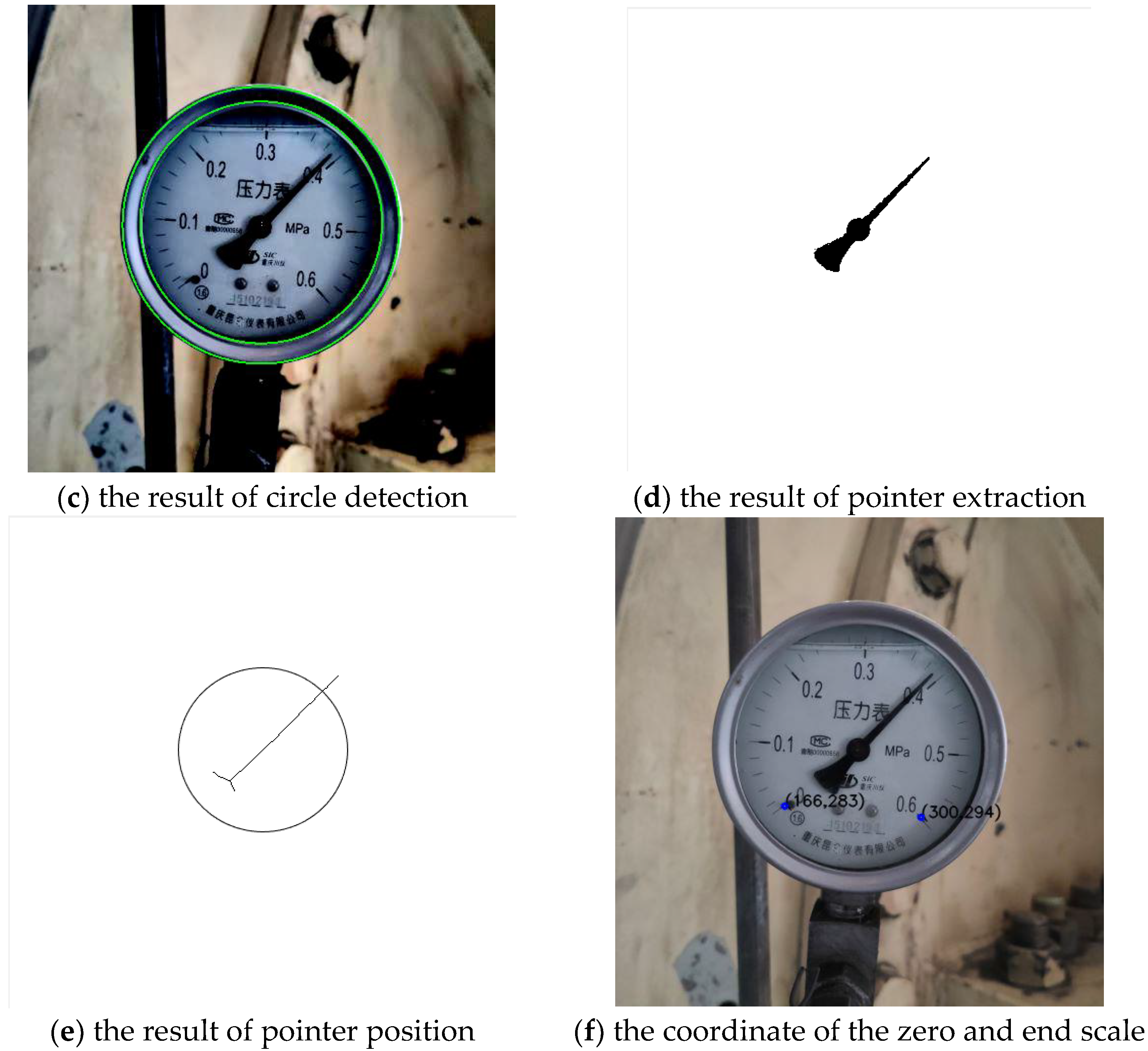
Figure 6c shows the result of the circle center extraction. Although the extraction result obtained the inner and outer contours of the dial, it did not affect the location of the center of the circle.
Figure 6d–f shows the pointer obtained by using the difference between the template and the original image, and then refined the pointer to draw a circle with an appropriate radius. The coordinates of the positioning pointer were determined by the intersection of the specified circle and the refined pointer. When drawing a circle, in order to reduce the deviation caused by incomplete pointer extraction, the radius of the circle should be increased as much as possible under the premise of ensuring that it can intersect with the refined pointer. This is because the radius of the selected circle is proportional to the distance from the intersection to the scale line. The larger the radius of the circle was, the higher the accuracy of the reading was.
Figure 6f shows the obtained coordinates of the initial scale value. Finally, the pointer reading was obtained using the angle method.
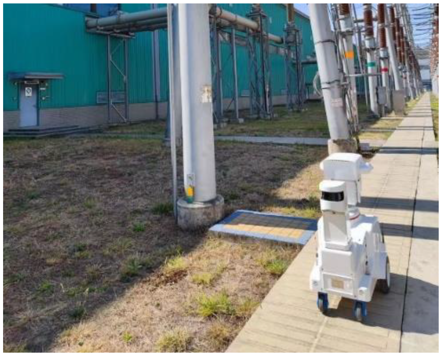
3.1. Introduction of the Test Platform
The inspection robot used in the experiments is shown in
Figure 7. The head of the inspection robot is equipped with an infrared thermography and a visible light camera, which can be rotated in all directions to obtain an image. Then, the image is transmitted to the SOC for identification. Its battery life can reach 5–6 h, standby for 24 h and can complete the following two working modes: automatic inspection and manual inspection.
3.2. Verify the Validity of MSRCR
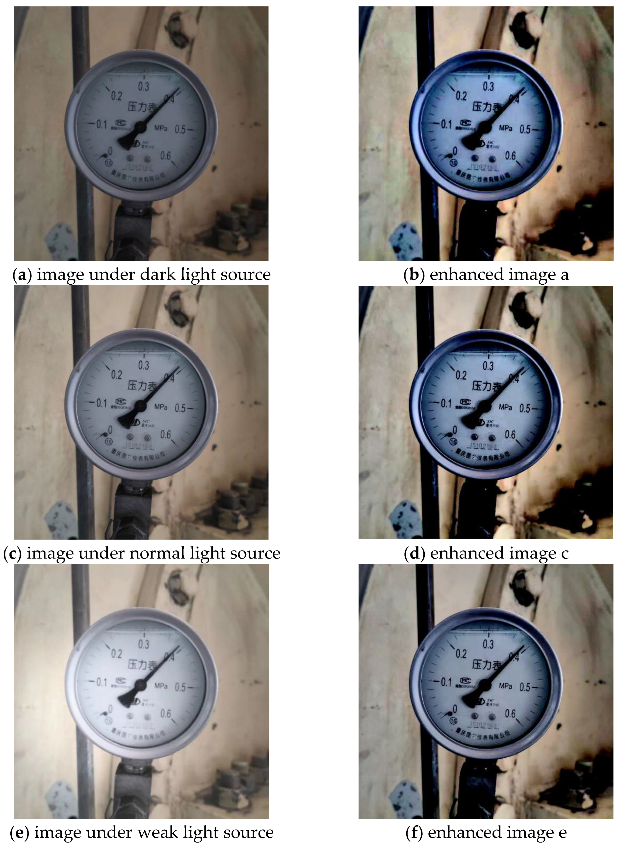
To verify the robustness of the MSRCR algorithm, this paper used a set of images with different light sources.
Figure 8 compares the experimental results of the MSRCR algorithm. In
Figure 8, the light source of the first two images is dark, the light source of the middle two images is normal and the light source of the last two images is weak.
The experimental results show that the contrast of the image processed using the MSRCR algorithm significantly improved while reducing the influence of different brightness levels. Dark and ordinary light sources have a slight effect on the image; therefore, the enhancement effect is not particularly obvious. However, for images under strong light sources, especially in areas where the strong light has greater influence, this information will be highlighted to offset the defects of image color distortion and ensure image clarity. In general, the experiment basically eliminated the influence of image brightness, and proved the effectiveness of MSRCR in the recognition system, which can be used to eliminate the influence of light on the dial.
3.3. Center Extraction
To verify the speed and accuracy of the circle center detection algorithm in this paper, this paper selected 10 images as experimental data. The division values of the pressure gauges in images 1–3, 4-6, 7-10 are 0.02, 0.02 and 0.05 respectively, and the corresponding measurement ranges are 0–0.6 MPa, 0-1Mpa, and 0-25Mpa.
Table 2 compares the experimental results of the circle center recognition using manual labeling, Hough circle detection and the method proposed in this paper. The absolute error of the circle center is the distance between the recognition value and the manually measured value.
As can be seen from
Figure 6c, more than one circle, such as the outer contour of the nut in the dial, be detected by mistake. To reduce the error, the radius threshold r is set. If the detection result radius is greater than r, the center coordinate will be output; otherwise, it will be omitted. The average value of the center coordinates is output as the final result.
According to the experimental result
Table 3, it can be seen that the average absolute error of the Hough circle detection method is 4.806%, and the average running time is 1.8913 s. The average absolute error of the circle detection method proposed in this paper is 2.579%, and the average running time is 0.02906 s. Therefore, from the perspective of rapidity and accuracy, the proposed circle detection method in this paper provides a significant improvement. Meanwhile, due to the low accuracy of Hough circle detection, the false detection rate is high, which leads to a long running time. Indeed, there is good performance with respect to recognition accuracy and running time.
3.4. Position Ten Dial Gauges
To evaluate the accuracy of the pointer positioning algorithm in this paper, the above 10 images were also selected as experimental data.
Table 4 compares the experimental result of manual marking, traditional Hough line detection, the algorithm of [
9] and our algorithm. The recognition angle is the angle between the pointer and the zero-scale line.
As can be seen from
Table 4, the average absolute error of the traditional Hough line detection is 0.34, and the average running time is 1432.31 ms. The algorithm [
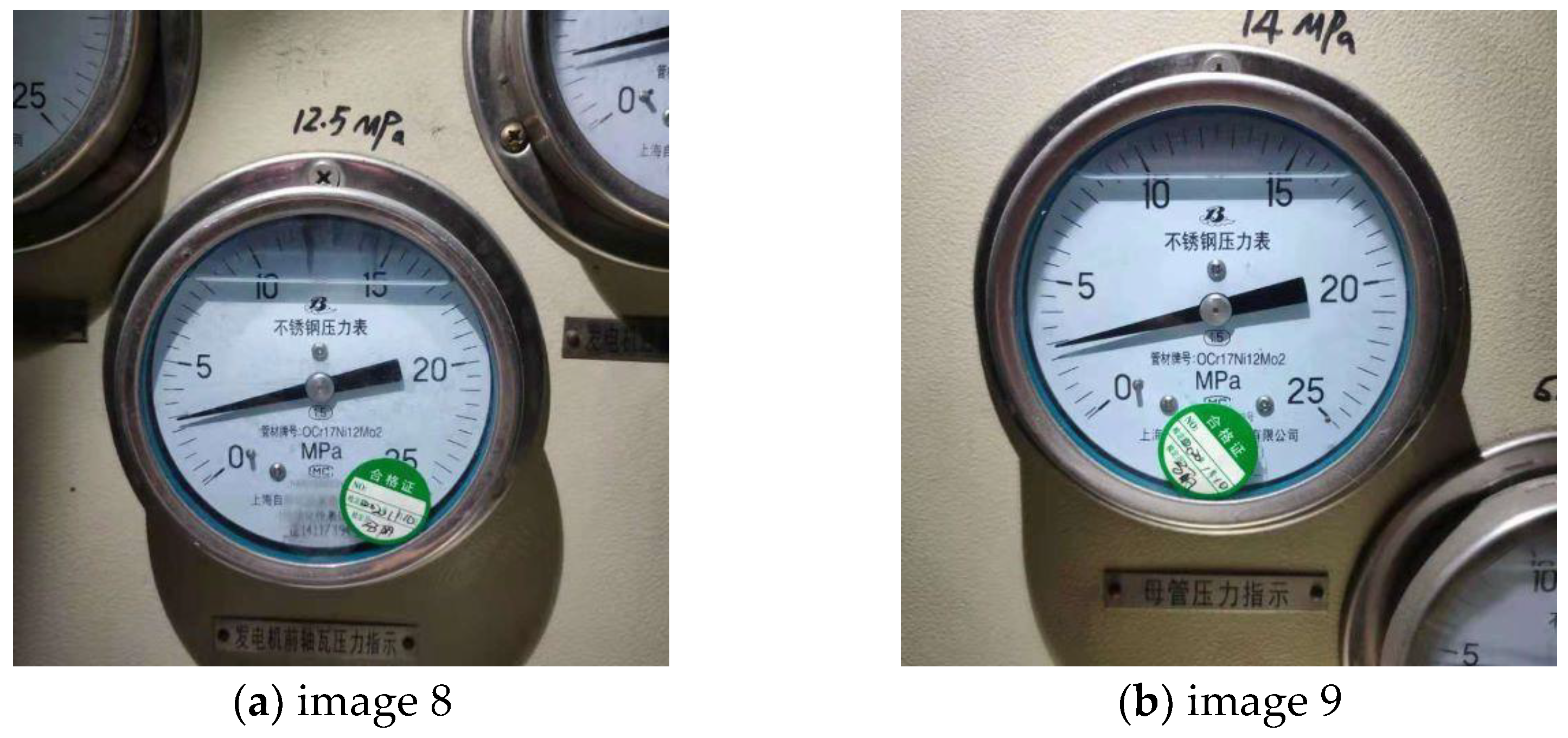
9] has an average absolute error of 0.144 and an average running time of 250.08 ms. The average absolute error of our algorithm is 0.06, and the average running time is 143.57 ms. In
Table 4, it should be noted that image 8 and image 9 have small errors in our algorithm, while the error in the Hough line detection and the algorithm of [
9] is large. As shown in
Figure 9, there are more labels on the dials of these three images, and the damping fluid just covers part of the scale values. Thus, our algorithm is barely disturbed by background images.
3.5. Measure Ten Dial Gauges
After completing the above experiment, it is time to complete the last step of the whole algorithm: reading. As shown in
Table 5, the average relative error in the algorithm from [
9] is 7.044%, the algorithm from [
10] is 1.200% and our algorithm is 0.994%. Therefore, compared with the previous two methods, the relative error of our algorithm is significantly reduced. In
Table 5, the algorithm [
9] has a larger relative error for images 7–10. This is because the algorithm [
9] is based on Hough line detection. There are many straight lines detected during processing that lead to large false detections. Moreover, the division value of images 7–10 is large. A small angle deviation during positioning will cause large reading error. Although the absolute error of center extraction of our algorithm is about 2.5%, it does not affect the overall reading error. It indicates that the accuracy of the center detection has little effect on the reading results, and the main influencing factor is the accuracy of the pointer positioning, especially for instruments with high division value.
According to the experimental results, there are still errors in the recognition of the proposed dial gauge readings. The main reason is that the pointer positioning accuracy is not high enough. When the angle method is used to obtain readings, slight angle deviations will cause large reading errors. In addition, light and shadow may affect the image quality when collecting images, which leads to incomplete pointer extraction and deviation of positioning.
4. Conclusions
In this paper, a dial gauge automatic recognition algorithm based on coordinate positioning is proposed, which can be applied in inspected robots in complex background environment. This method is not affected by background factors, and accurate readings can be obtained by directly extracting the center of the circle and the point coordinates on the positioning pointer from the dial. Firstly, the MSRCR algorithm is used to reduce the impact of lighting, which is good for the later experimental steps to extract coordinates accurately. Secondly, the meter’s center is recognized by using the circle detection method based on the arc-support line segment. Then, the pointer can be extracted by constructing a pointer-free template, and the concentric circle algorithm is used for the refined pointer result, which achieves the purpose of positioning the pointer accurately. Finally, the angle method is used to realize automatic reading. The experimental results show that the proposed algorithm is fast, accurate, less affected by light and has a strong anti-interference ability against the background image of the dashboard.


