Communication

Automatic Creation of Heuristic-Based Truck Movement Paths for Construction Equipment Control

Department of Civil Engineering, Seoul National University of Science and Technology, Seoul 010811, Korea
*
Author to whom correspondence should be addressed.
Appl. Sci. 2021, 11(13), 5837; https://doi.org/10.3390/app11135837
Submission received: 11 May 2021 / Revised: 10 June 2021 / Accepted: 21 June 2021 / Published: 23 June 2021

Abstract

:
The demand for technologies related to smart construction is rising as the need for increased productivity in the field of construction becomes ever more important. The fourth industrial revolution has accelerated the growth of advanced technologies, including artificial intelligence, 5G, the internet of things, and more, and these technologies are key in relation to smart construction. During the construction phase of our study, a truck travelled along a temporary road within a construction site. Thus, optimizing the location of the temporary road enhances the truck’s moving path, resulting in increased productivity in the road construction process. Thus, in this work, the concept of automating a path for construction equipment (a truck) is proposed. The construction site was divided into cells, where five factors were suggested to create a cost model that could automatically be used to create one of the most efficient paths for construction equipment. With the proposed concept, one can automatically create one of the most efficient paths when deciding the location for a temporary road during construction.

1. Introduction

The fourth industrial revolution era demands rapid developments in many sectors, including the construction industry. Automation research is actively conducted in various fields such as the manufacturing sector and the computer sector. Construction is also undergoing a period of change, as technologies such as drones, BIM (building information modeling), GPS (global position system), and sensors develop. However, construction shows relatively low productivity compared to higher productivity in the field of manufacturing. In addition, despite technological advances, human casualties related to the construction industry continue to rise; it has been reported that human casualties occur four times more frequently in construction than in other industries. Among them, construction equipment-related accidents at U.S. construction sites account for about 25 percent of the total [1] and, according to the Korea Occupational Safety and Health Agency, the number of deaths in construction is around 500 in the country.
Around the world, policies to improve construction productivity and safety by applying fourth industrial revolution-related technologies are being pursued. In the UK, construction 2025 [2] aims to reduce construction periods by 50% and increase construction productivity by 20% by 2025 [3]. Singapore came up with the Construction Productivity Roadmap [4] to improve construction productivity by 2–3% every year, and the Ministry of Land, Infrastructure, and Transport in Korea announced the sixth Basic Construction Technology Promotion Plan to increase construction productivity by 40% and improve safety by 2022.
Continuous efforts to improve smart construction technologies are being carried out, and their main purpose is to develop smart technologies such as artificial intelligence, BIM, robots, IoT (Internet of things) sensor networks, and unmanned remote environments to enhance the productivity and safety of construction [5,6,7,8,9,10,11]. Smart construction technology development areas also include construction equipment automation and control technology [12,13], road structure smart construction technology [14], smart safety integrated control technology [15,16], and smart construction digital platforms [17].
BIM is a technology that forms the basis of digital construction, and it is presented to effectively create, integrate, manage, and recycle information generated during the entire life cycle of a structure. It is a technology that allows information to be shared continuously. Standards are established for compatibility of BIM data with smart construction, and some of the research can be found in [18,19,20]. Currently, BIM is considered a basic element of digital construction that is mainly applied to 3D visualization, design error review, constructability review, and quantity calculation. However, due to various limitations, the generated BIM model has its limits when used as a tool for smart construction in connection with construction equipment.
Construction equipment automation and control technology was introduced into the construction industry because of worker safety, shortages of skilled workers, reduced productivity, and economic feasibility [21]. In the early days of construction automation equipment, it was mainly used to perform simple tasks by being used in a specific type of work. Recently, construction equipment in the form of multi-functional collaboration has been developed. However, the reason that much of the automation equipment used in actual construction sites is not available is that, unlike the standardized work environment in the manufacturing industry, the site conditions are greatly affected by the external environment and are highly variable. Currently, each country is developing a system composed of multiple types of construction equipment that can be linked to CAD/CAM systems during the construction stage [22].
The purpose of this study is to present a methodology for automatically generating a moving path of a truck based on earthwork BIM in a road site as part of the development of construction equipment automation and control technology. In general, a truck moves around a temporary road, so optimizing the location of a temporary road ultimately optimizes the truck’s moving path, resulting in increased productivity in the entire road construction process. In this study, a method for establishing a soil distribution plan based on BIM was proposed, and the factors for determining the location of a temporary road were identified by examining the current method and human beings’ heuristics for creating temporary roads. In addition, weight values were created and applied to the factors to create a cost model. Finally, a case study was conducted using real data acquired from a construction site.

2. Earthwork Background

2.1. Earthwork in General

Earthwork is a basic process in most construction works, and it has a great influence on productivity and construction cost. To date, various forms of research and development have been conducted to increase the efficiency of earthwork. Earthwork can be divided into 2D-based earthwork (such as land development) and linear earthwork (such as road work and railroad work). In the 2D-based earthwork, a two-dimensional configured target area is divided into cells of a certain size, divided into cut cells and fill cells, and various optimization techniques are applied to minimize the distance for soil distribution. In the case of linear earthwork, the mass-haul diagram method and the traditional linear model are mainly used to establish an optimized distribution plan for cut cells and fill cells. There are several methodologies applied in the establishment of the soil distribution plans [23,24,25,26,27,28]. Past earthwork-related studies established a plan for the entire earthwork site, and later studies suggested a methodology for establishing a plan that excluded the deterrent and various obstacle areas. However, the difficulty of applying the proposed methodologies to the sites in Korea is that there is a lot of variability in the process of defining soil allocation. For example, an exclusion zone could randomly occur due to unaccepted land expropriation, which could affect the movement path of a truck within the site. Previously, the soil distribution plan was used only for the purpose of establishing the process plan and calculating construction costs. However, from the perspective of applying the system to smart construction, the volume distribution plan should be linked as an input for construction equipment, and it should be used as essential information to maximize efficiency of the work site. In this respect, the soil distribution plan should reflect the actual site situation while guaranteeing a minimum travel distance for the vehicle.
Examining the representative earthwork planning and earthwork-related commercial systems, Sokkia proposes a system that enables high-precision work by combining 3D information, GPS, various sensors, and communication technologies [29]. Trimble provides the function of accurately performing earthmoving work without installing survey piles by applying machine guidance technology based on GPS, graphic technology, communication technology, and MMI (man–machine interface). It also provides a function for managing a fleet [30]. Fujita and Maeda Construction in Japan developed a system for remote earthmoving work while ensuring the safety of workers. In Korea, Doosan Infracore and several universities collaborated to develop an intelligent excavator [31] and conducted field experiments to demonstrate the potential of unmanned earthmoving. Additionally, a fleet management system [32,33] that can establish an optimal earthwork plan and support the operation of construction equipment, while sharing necessary information in real time, has been developed.

2.2. Soil Distribution Plan for a Road Construction

In general, the generation of a construction plan, such as road construction, uses a mass curve, and the curve is created by accumulating the deficiency of the soil volume along the longitudinal line of the site. The mass curve is used to determine which equipment to use by determining the balance distribution of cut soil and the direction of soil movement to the end, and then calculating the average transport distance of the soil volume. It is difficult to apply the mass curve for the entire earthwork section in the field due to timely differences, spatial differences, and work sections. The actual work is for the area where compensation has been completed within the construction section, and the volume distribution plan and equipment input plan are established by dividing them into small work sections rather than the entire construction site. In addition, soil volume is not moved directly from the cutting area to the filling area when it is synchronized, but cut soil is temporarily loaded in an appropriate position and then soil compaction is carried out. In addition, a construction plan does not provide information about which position to move the soil volume in the transverse direction in the soil distribution curve. Therefore, soil planning for smart earthwork needs to solve the problems of the existing mass curve. Thus, the earthwork planning method for a road construction is suggested as follows.

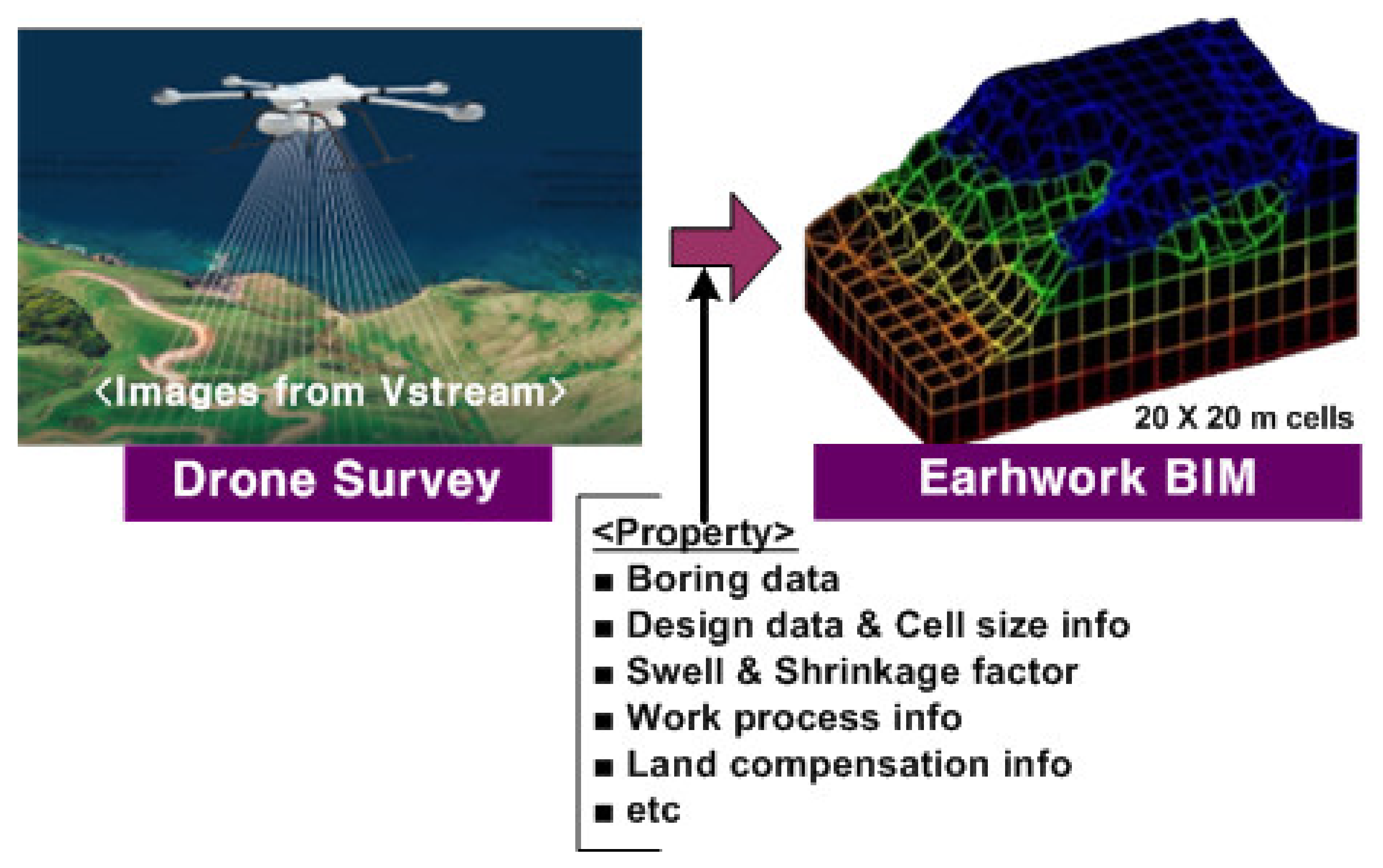
2.2.1. Earthwork BIM Model Formation

For smart earthwork, a 3D scanner or a drone is used to scan a field’s topography, and a triangular network is formed using raw scan data to complete a surface model (Figure 1). In order to establish an earthwork plan, the entire area is divided into cells 20 × 20 m in size, and location information for each cell, boring data, conversion factor of soil, design information, work allocation information, work progress information, and land compensation information are used to create a BIM model.

2.2.2. Dividing and Establishing Earthworks Plans for Only Available Areas in the Site

Only the part where land compensation has been completed within the construction site is set as the target for distribution of soil volume, and the cut soil volume for each station is checked using the mass curve. An earthwork plan is established by dividing the entire road construction section into smaller areas. The soil distribution established for each divided area is matched with the cut cell and the fill cell using the transport algorithm. In a previous study, the soil distribution plan was established based only on the transport distance between cut cells and fill cells, but this study considers the heuristics of experts and experienced workers in the field, and reflects the cut and fill volume, transport distance, passibility, civil complaints factor, ground slope, and ground condition to be matched to the cut cell and the fill cell.
For smart earthworks, the cell size is further subdivided in consideration of the construction equipment’s specifications (dozer blade length or effective compaction width) for parts that are less than 60 m in terms of transport distance (Figure 2). In the case of performing the filling work, the subdivided cell is used to determine the location of the stacking position, and the dozer and compactor are used to provide the exact position to perform the work.

2.2.3. Task Packages and Provision of Transverse Soil Distribution Information

The match between the cut cell and the fill cell, according to the result of soil distribution, is called “task package”. As suggested by Kim et al. (2003) [34], the task package is divided into five types and has attribute information on the package number, cell location, ground type, work volume, transport distance, and work status. By establishing an earthwork plan, a number of task packages are formed, and the priority of their performance in a certain order is determined. Task package information is provided to construction equipment in real time for optimal work performance. Existing soil planning does not provide information on lateral soil movement but, when using an earthwork BIM, information can be accurately transmitted to workers and construction equipment.

3. Construction Equipment (Truck) Movement Path Creation

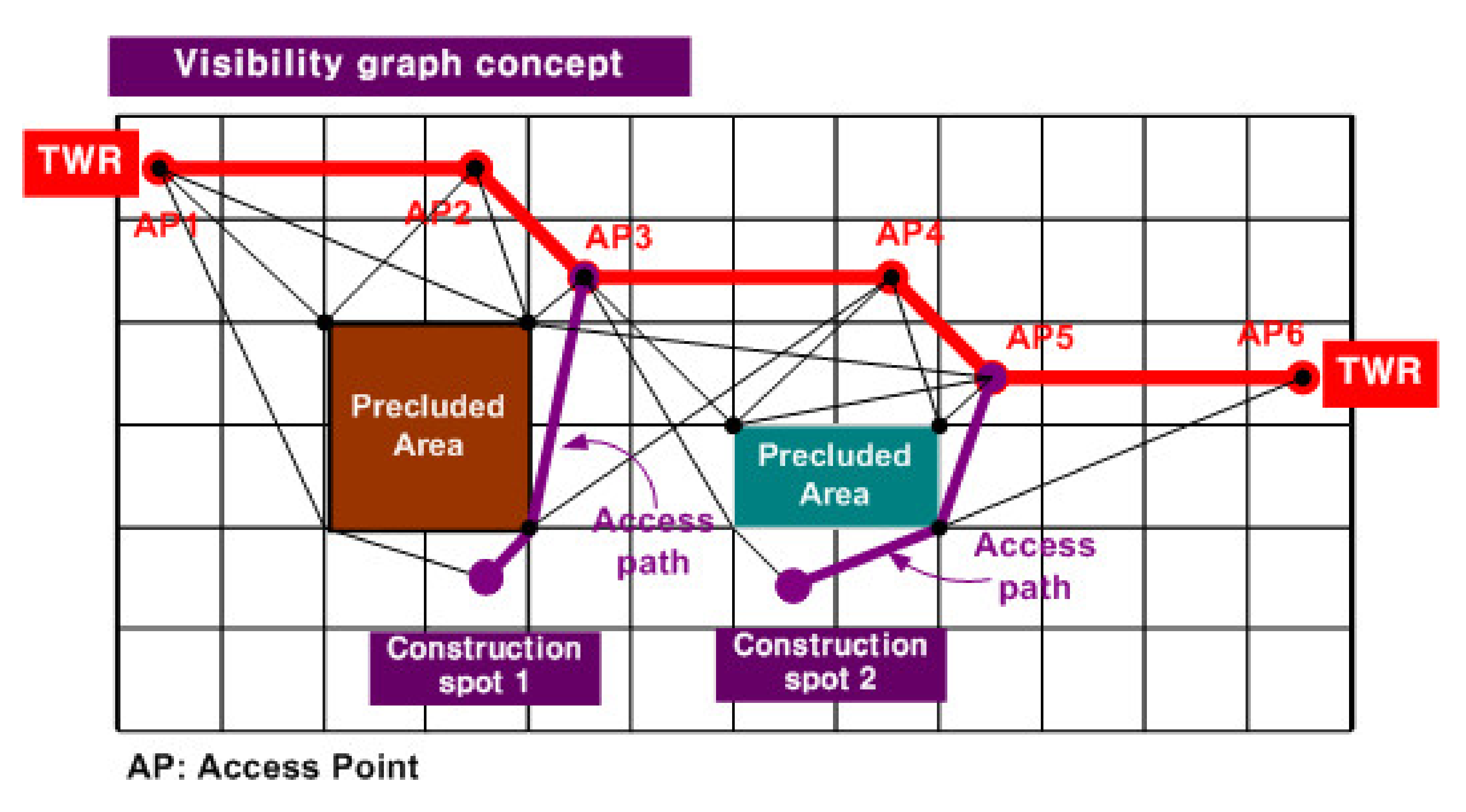
3.1. Heuristic Investigation for Generating Temporary Work Roads

The location of a temporary road for trucks during a construction phase is an important factor, as distance can affect the overall cost of the process. However, despite these important factors, only a limited number of studies can be found in relation to this problem. In addition, Korea’s specifications for temporary roads are somewhat different for each design standard, and only basic contents related to road installation are presented. For this reason, most of the time, temporary roads are planned and installed by experienced workers at the start of construction. Thus, for this study, 18 construction managers and experienced workers working at 9 companies (Figure 3) were surveyed to analyze their know-how and heuristics regarding the installation of temporary roads. Here, the important factors when deciding temporary roads are summarized in Table 1. Next, five important factors were selected and weight values for each of these factors were set based on the AHP (analytic hierarchy process) technique. These values can be seen in Table 2, where the weight values were 42%, 12%, 14%, 17%, and 15% for transport distance, slope, cut soil, civil complaints, and distance to structure, respectively. Here, the consistency index (CI) was 7.7%.

3.2. How to Create an Optimal Temporary Road in the Field

At the beginning of the construction stage, if the location of the entrance/exit route is determined, a temporary road must be created for the construction equipment to move. The movement from the cut cell to the fill cell of the task package formed by the soil distribution plan should not be a straight line between the two cells. Since the moving path of construction equipment is determined according to the location of the temporary road, the optimal location of the temporary road has a great influence on construction productivity. Figure 4 shows the process of creating a temporary road, and it provides information regarding the detailed cells of a temporary road, reaching from the start point to the end point using a double linked list data structure.
After determining the location of the entrance and exit of the site, the interior area of the site is divided into detailed cells that are the width of the temporary road. A doubly linked list data structure is formed, the cell where the access road is located is set as the starting node of the data structure, and this node is set as the current cell. The current cell acts as a pointer in the data structure. After calculating the movement cost between the current cell and neighboring cells, the cell with the lowest movement cost is selected and added as a new node in the doubly linked list; then, it is established whether this new node is the same as the end cell corresponding to the exit path. If it is the same as the end cell, the location of the temporary road in the site has been determined. If it is not the same, the pointer is moved to designate a new node as the current cell, and the next node for constructing the temporary road is sought out.
As shown in Figure 5, if a cell becomes part of a temporary road after the current cell is selected when constructing a temporary work road list, five cells around the current cell become candidate groups, among which the cell requiring the least cost is selected. The following are the elements that make up the cost model.
1.
Distance to the end cell: DE
The distance between each cell around the current cell and the end cell is calculated as follows. A shorter distance means a more efficient outcome.
DE = x 1 x 2 2 + y 1 y 2 2 + z 1 z 2 2
Note: end cell center coordinates ( x 1 ,   y 1 , z 1 ), peripheral cell center coordinates ( x 2 , y 2 , z 2 )
2.
Work volume (WV)
Work volume refers to the amount of cut and fill in each cell located around the current cell. When constructing a temporary road, it is advantageous in terms of construction costs to minimize the cut and fill volume where possible. As shown in Figure 6, the cut and fill volume can be calculated from the information between the temporary road surface planned in the earthwork BIM model and the original ground. If a temporary road is created according to a formation level, it can be used immediately as a main road surface in the future.
3.
Gradient (G)
Gradient refers to the ground slope between the current cell and the cells located around it. Theoretically, it should be less than 20 degrees, which is the standard at which construction equipment can operate. In practice, it should not exceed 10 degrees, unless it is unavoidable. If possible, an area with a gentle slope should be preferred. As for the slope between the two cells, after calculating the average elevation of each cell, the slope is calculated using the two elevations. This is shown in Figure 7.
4.
Distance to the structure (DS)
If the location of the temporary road is constructed as close to the structure as possible based on the location information of the major structures mentioned in the blueprint, it is suitable for carrying various equipment and materials when constructing the structure. The calculation method is used by calculating the distance between the center coordinates of the cell where the structure is located at the center coordinates of each cell around the current cell.
5.
Distance to the source of civil complaints: DC
If there is an existing structure or building near the site, there is a possibility of complaints due to noise and vibration. Therefore, in order to minimize the occurrence of civil complaints, it is preferrable if the location of the temporary road is separated from the source of civil complaints, so that the standards stipulated by law can be satisfied. In this study, the calculation formula for predicting the noise and vibration generated during construction used the criteria suggested by the National Institute of Environmental Sciences, which is as follows:
S P L t = 10 log i = 1 n 10 S P L i 10 ,                         S P L 1 = S P L 0 20 Log r r 0
  • SPLt: Composite noise level of input equipment (dB(A));
  • SPLi: Individual noise level of input equipment (dB(A));
  • SPL1: Equipment noise level at the predicted point (dB(A));
  • SPL0: Noise level (dB(A)) at a certain distance (7.5 m, 15 m) from the noise source;
  • r: Distance from the noise source to the predicted point;
  • r0: Distance from the noise source to the reference measurement point.
During construction, 65 dB(A) was applied as the standard for living noise and 65 dB(V) was applied for the standard for living vibration. According to the results predicting the noise and vibration for each separation distance, in the case of excavators, trucks, and dozers, when noise standards are satisfied, vibration standards are automatically satisfied, so only the noise standards are reflected in the cost. In the case of the target truck of this study, it was suggested that 65 dB, which is the standard value, can be generated at an 85 m separation distance when two vehicles alternate; a cost estimation table was prepared based on this. The cost model reflecting the above factors is as follows. The weight of each item was determined based on a questionnaire by experts, and detailed score assignment methods are mentioned in Table 3.
Moving Cost = 0.42DE + 0.14WV + 0.12G + 0.15DS + 0.17DC
Some positional changes may occur in the initial temporary roads under the following circumstances. In these cases, temporary roads are re-established and limited to the section that needs to be changed:
(1)
When the location of the entry/exit in the site is changed;
(2)
When the length of the temporary road can be shortened because the site is newly accommodated;
(3)
When the contract for the leased site has expired and the site cannot be used;
(4)
When the construction of the structure is completed and there is no need to enter the area;
(5)
In case the position of the temporary road needs to be adjusted due to a civil complaint;
(6)
In case of flooding during the rainy season or loss due to natural disasters;
(7)
In case of conflict with other construction (for example, the start of new construction along the road’s route, etc.);
(8)
When a new bridge or tunnel is completed and it is possible to pass through.

3.3. Creating a Truck Path

When a truck enters a construction site through an access road, it moves along the temporary road installed. Most of the truck’s movement paths are the same as the location of the temporary road, and some movement paths are set in areas other than the temporary road, depending on the situation of the construction process. Figure 8 shows a visibility graph indicating the route for entering the construction location from each AP (access point) of the temporary road that can be generated by avoiding the removal area through which construction equipment cannot pass. In the concept of the Euclid shortest path, the shortest path is simply selected but, in this study, the entry path is also determined by considering the trafficability of construction equipment. Considering the drivability of construction equipment, moving to the temporary road as quickly possible and entering the construction area with the shortest route from the temporary road becomes an efficient access route. In order to enter construction zone 1, it is necessary to enter through the path through AP3; to enter construction zone 2, it is efficient to enter through the path through AP5.

4. Case Study

A Chungcheong Inland Expressway in South Korea, scheduled to be completed in April 2024, was selected as the subject of the case study. First, the road site floor plan measurement point and construction base information were input and, considering that the total width of the road was 8 m, an 8 × 8 m cell was formed on the floor plan. An earthwork BIM model was constructed based on photographic data using a drone, and the cell and earthwork BIM model based on the point of the floor plan were matched. When using an existing road, a temporary road was needed because the moving route became longer, so the location of the temporary road was automatically determined by the model presented in this study. As a result, the moving route of the truck was created.
As shown in Figure 9, the bridge (from Cell: E8 to Cell: G16) is under construction, so it is impossible for trucks to pass over it from the access road (S, Cell: C2) or the exit (T, Cell: G20). In the case of moving in the direction of the bridge, the position of the hypothetical road was determined. A moving cost model reflecting an expert’s heuristic was used to search for a path from the entrance road to the exit, and the results are displayed in yellow lines. From Cell D9 to Cell D15, the construction company has opened and is currently using a temporary road (green), which is consistent with the results presented in this case study; the inconsistent areas are land that can be used when opening a temporary road at the construction site. It was found that there was a difference between using a part that was not compensated for and using a part of the existing agricultural road.
In most cases, the location of the temporary road is not even determined at the design stage, and it is mostly determined by the experience and intuition of the site manager after the road site is opened. Since the methodology presented in this study cannot reflect all the special conditions of the site, it cannot always guarantee that the optimal temporary road location will be selected. However, it is meaningful in that it is systematized to determine the best temporary road location in a given condition by reflecting design information, earthwork BIM information, and the heuristics of experts. The optimization of a temporary road is used to enhance the movement path of a truck, which will ultimately bring about an improvement in the productivity of earthworks. In addition, if the location of the temporary road is determined by applying the methodology presented in this study from the design stage, the cycle time of construction equipment can be estimated. Thus, based on this, it can be used to optimize the combinations of construction equipment that should be used. One might say that it plays an important role as an element in the technology of construction equipment automation and control systems.

5. Conclusions

The purpose of this study was to present a methodology for automatically generating the movement path of a truck in a road site based on earthwork BIM information, and to present element technology for efficient construction equipment control. The concept of automating a path for construction equipment (truck) is proposed with five factors to determine a route. Each of the factors were multiplied by weighted values that were determined by analyzing the survey conducted for this study. When analyzing the survey data acquired from the experts in this related field, the five most important factors were distance to the end cell, work volume, gradient, distance to the structure, and distance to the source of civil complaints. Using these aforementioned factors, the overall moving cost could be determined and the path for the truck could be automated where the proposed concept was applied for evaluation in a real construction area in the Chungcheong area, South Korea. The outcome was positive and the proposed concept could be used in the future at construction sites when automatically determining the path for a truck during the construction phase.

Author Contributions

S.-K.K. was responsible for conceptualization and methodology of the work; J.-W.J. carried out investigation and validated data; W.S.N. participated in algorithm optimization, translating, and writing the manuscript. All authors have read and agreed to the published version of the manuscript.

Funding

This research was conducted with the support of the “National R&D Project for Smart Construction Technology (No.21SMIP-A157120-02)” funded by the Korea Agency for Infrastructure Technology Advancement under the Ministry of Land, Infrastructure and Transport, and managed by the Korea Expressway Corporation.

Institutional Review Board Statement

Not applicable.

Informed Consent Statement

Not applicable.

Data Availability Statement

Not applicable.

Conflicts of Interest

The authors declare no conflict of interest.

References

  1. Venugopal, M. Construction Fatalities in the United States between 2009–2018. Int. J. Res. Appl. Sci. Eng. Technol. 2020, 8, 1129–1133. [Google Scholar] [CrossRef]
  2. Son, T.H. From Constructing the Team to Construction 2025. CERIK Q. Rep. Summer CERIK 2016, 49–52. [Google Scholar]
  3. Cho, J.Y. Strategies and Implication of Japanese Construction Industry in the 4th Industrial Revolution. In Constriction Policy Review Report 2017-03; Korea Research Institute for Construction Policy: Seoul, Korea, 2017; Volume 3. [Google Scholar]
  4. National Archives of Singapore 2nd Construction Productivity Roadmap Media Factsheet. Available online: http://www.nas.gov.sg/archivesonline/data/pdfdoc/20170307002/ (accessed on 9 June 2021).
  5. de Soto, B.G.; Skibniewski, M.J. Future of robotics and automation in construction. In Construction 4.0: An Innovation Platform for the Built Environment; Routledge: Abingdon, UK, 2020; pp. 289–306. [Google Scholar]
  6. Chen, Q.; de Soto, B.G.; Adey, B.T. Construction automation: Research areas, industry concerns and suggestions for advancement. Autom. Constr. 2018, 94, 22–38. [Google Scholar] [CrossRef]
  7. Heikkilä, R.; Makkonen, T.; Niskanen, I.; Immonen, M.; Hiltunen, M.; Kolli, T.; Tyni, P. Development of an Earthmoving Machinery Autonomous Excavator Development Platform. ISARC. Proc. Int. Symp. Autom. Robot. Constr. 2019, 36, 1005–1010. [Google Scholar]
  8. Kim, Y.S.; Oh, S.W.; Cho, Y.K.; Seo, J.W. A PDA and wireless web integrated system for quality inspection and defect management of apartment housing projects. Autom. Constr. 2008, 17, 163–179. [Google Scholar] [CrossRef]
  9. Kimoto, K.; Endo, K.; Iwashita, S.; Fujiwara, M. The application of PDA as a mobile computing system on construction management. Autom. Constr. 2005, 14, 500–511. [Google Scholar] [CrossRef]
  10. Choi, Y.; Kim, Y. Applications of Smart Helmet in Applied Sciences: A Systematic Review. Appl. Sci. 2021, 11, 5039. [Google Scholar] [CrossRef]
  11. Ahmed, N.; Hong, A.J.; Ku, H.; Moon, S.; Moon, S. Technical review of automated system application to earthworks in Australia. Proc. Int. Symp. Autom. Robot. Constr. 2017, 34, 594–601. [Google Scholar]
  12. Schimanski, C.P.; Marcher, C.; Toller, G.; Monizza, G.P.; Matt, D.T. Enhancing Automation in the Construction Equipment Industry Through Implementation of BIM. In Proceedings of the International Conference on Cooperative Design, Visualization and Engineering, Mallorca, Spain, 6–9 October 2019; pp. 64–73. [Google Scholar]
  13. Prasad, K.N.; Agrawal, V.M. Automation and Robotics in the Construction Industry-a Review. I Manag. J. Future Eng. Technol. 2019, 14, 49. [Google Scholar]
  14. Li, R.Y.M. Smart construction safety in road repairing works. Procedia Comput. Sci. 2017, 111, 301–307. [Google Scholar] [CrossRef]
  15. Jiang, W.; Ding, L.; Zhou, C. Cyber physical system for safety management in smart construction site. Eng. Constr. Archit. Manag. 2020, 28, 788–808. [Google Scholar] [CrossRef]
  16. Hammad, A.; Vahdatikhaki, F.; Zhang, C.; Mawlana, M.; Doriani, A. Towards the smart construction site: Improving productivity and safety of construction projects using multi-agent systems, real-time simulation and automated machine control. In Proceedings of the 2012 Winter Simulation Conference (WSC) IEEE, Berlin, Germany, 9–12 December 2012; pp. 1–12. [Google Scholar]
  17. Schweigkofler, A.; Monizza, G.P.; Domi, E.; Popescu, A.; Ratajczak, J.; Marcher, C.; Matt, D. Development of a digital platform based on the integration of augmented reality and BIM for the management of information in construction processes. In Proceedings of the IFIP International Conference on Product Lifecycle Management, Turin, Italy, 8 December 2018; Springer: Cham, Switzerland, 2018; pp. 46–55. [Google Scholar]
  18. Kim, H.; Chen, Z.; Cho, C.S.; Moon, H.; Ju, K.; Choi, W. Integration of BIM and GIS: Highway cut and fill earthwork balancing. Comput. Civ. Eng. 2015, 2015, 468–474. [Google Scholar]
  19. Park, T.S.; Park, H.S. The Current Status and Facilitation Strategy of BIM for Civil Infrastructure Projects. J. Korean Soc. Civ. Eng. 2015, 38, 133–140. [Google Scholar]
  20. Kim, H.; Kim, J.; Seo, J.; Shim, H. The Improvement of Point Cloud Data Processing Program for Efficient Earthwork BIM Design. Korean J. Constr. Eng. Manag. 2020, 21, 55–63. [Google Scholar]
  21. Kim, S.K.; Lee, J.B.; Kim, Y.S. A Study on Core Technologies and Technological Innovation Strategies for Construction Automation. J. Korean Soc. Civ. Eng. 2004, 24, 795–803. [Google Scholar]
  22. Lim, S.Y.; Kim, S.K. Productivity analysis using a Fleet Management System for Construction Equipment. J. Korean Soc. Civ. Eng. 2020, 40, 587–595. [Google Scholar]
  23. Easa, S.M. Earthwork allocations with linear unit costs. J. Constr. Eng. Manag. 1988, 114, 641–655. [Google Scholar] [CrossRef]
  24. Jayawardane, A.; Harris, F. Further development of integer programming in earthwork optimization. J. Constr. Eng. Manag. 1990, 116, 18–34. [Google Scholar] [CrossRef]
  25. Lee, C.K.; Kim, S.K.; Sung, Y.J. A Study on 2D-Based Earthwork Planning Methods. KSCE J. Civ. Eng. 2003, 23, 349–357. [Google Scholar]
  26. Kang, T.W.; Cho, Y.H. The Study on the Optimized Earthwork Transfer Path Algorithm Considering the Precluded Area of Massive Cutting and Banking. J. Korean Soc. Road Eng. 2011, 13, 1–8. [Google Scholar]
  27. Guden, H.; Sural, H. A polynomial algorithm for the earthwork allocation problem with borrow and waste site selection. J. Oper. Res. Soc. 2016, 68, 1085–1093. [Google Scholar] [CrossRef]
  28. Ji, M.G.; Park, J.K.; Kim, D.H.; Jung, Y.H.; Park, J.K. Earthwork Planning via Reinforcement Learning with Heterogeneous Construction Equipment. J. Korea Soc. Simul. 2018, 27, 1–13. [Google Scholar]
  29. Sokkia Korea Positioning Instruments Catalog. Available online: https://www.sokkia.co.kr/default/1004web/dd/d08.php (accessed on 9 June 2021).
  30. Trimble Earthworks Grade Control Platform. Available online: https://construction.trimble.com/earthworks (accessed on 9 June 2021).
  31. Kim, S.K.; Seo, J.; Russell, J.S. Intelligent navigation strategies for an automated earthwork system. Autom. Constr. 2012, 21, 132–147. [Google Scholar] [CrossRef]
  32. Kim, S.K.; Lim, S.Y. A Study on the Improvement of a Fleet Management System for Construction Equipment. J. Korean Soc. Civ. Eng. 2017, 37, 1063–1076. [Google Scholar]
  33. Smart Construction Tech Research Group. Integrated Fleet Management and Smart Construction Technology in the 4th Industrial Revolution. Available online: https://www.youtube.com/watch?v=frPgTe59YVc (accessed on 9 June 2021).
  34. Kim, S.K.; Russell, J.S. Framework for an intelligent earthwork system. Part II. Task identification/scheduling and resource allocation methodology. Autom. Constr. 2003, 12, 15–27. [Google Scholar]
Figure 1. Earthwork BIM generation.
Applsci 11 05837 g001
Figure 2. Site sub-division, soil distribution, and 2nd cell decomposition (c.f. Kim et al., 2021).
Applsci 11 05837 g002
Figure 3. Information on interviewee.
Applsci 11 05837 g003
Figure 4. Process of generating a temporary work road list.
Applsci 11 05837 g004
Figure 5. Elements of a cost model and TWR list.
Applsci 11 05837 g005
Figure 6. Work volume calculation.
Applsci 11 05837 g006
Figure 7. Gradient calculation.
Applsci 11 05837 g007
Figure 8. Access to a construction spot form the TWR.
Applsci 11 05837 g008
Figure 9. Application of the proposed idea on Chungcheong Inland Expressway, South Korea.
Applsci 11 05837 g009
Table 1. Elements for a temporary work road construction.
Important Factors
Temporary road design criteria
Design speed: 15 km/h
Inclination: within 20°
Width: 5~8 m (over 2.75 m in a downtown area)
Pavement: concrete 20 cm, subbase 20 cm
Number of lanes (Round trip): 1 lane with 400 or fewer equipment/ 2 lanes for 400 or more equipment
Others: 0.5 m higher than the ordinary water level
Temporary road location selection
Transport distance: shortest distance
Civil complaint: minimum complaints
Compensate for land: whether or not to compensate for land
Cut and fill volume for temporary road construction: minimum soil volume
Proximity to structure: minimum distance to structures
Inclination: as close within 10° as possible
Accessibility from the existing road: convenient access location
Whether damage occurs during the rainy season: location where there is no damage
Conflicts with other types of work: a location to avoid conflicts
Period of retention: locations that can survive for a long time
Constructability: location where construction work is easy
Table 2. Relative comparisons among elements for a temporary road construction.
ClassificationDEGWVDCDSWeight
DE13.532.55630.42
G0.28611.4170.7780.9310.12
WV0.3330.70611.0831.250.14
DC0.3911.2860.92311.6670.17
DS0.3331.0750.8000.60010.15
(DE: distance to the end cell, G: gradient, WV: work volume, DC: distance to the source of civil complaints, DS: distance to the structure).
Table 3. Cost accounting by elements of the moving cost model.
ElementCaseCost
DEMax distance (MaxDE) from surrounding cells of the current cell to the end cell1
Others D i s t a n c e   f r o m   a   s e l e c t e d   c e l l   t o   t h e   e n d   c e l l M a x   D E
WVCutMax cut volume (MCV) among surrounding cells1
Others C u t   v o l u m e   o f   a   s e l e c t e d   c e l l M C V
Fill{Max fill volume (MFV) among surrounding cells} × (1/C)
C: Soil shrink factor
1
Others F i l l   v o l u m e   o f   a   s e l e c t e d   c e l l M F V
Cut + Fill
(Mixed)
Max mixed volume (MMV) among surrounding cells
Mixed volume =
|Cut vol—{Fill vol ×(1/C)}|
C: Soil shrink factor
1
Others M i x   v o l u m e   o f   a   s e l e c t e d   c e l l M M V
GSlope 20°~30°1
Slope 10°~20°0.5
Slope 0°~10°0
DSMax Distance (MaxDS) from surrounding cells of the current cell to a main structure1
Others D i s t a n c e   f r o m   a   s e l e c t e d   c e l l   t o   a   m a i n   s t r u c t u r e M a x   D S
DCWithin 85 m1
85~130 m0.7
130~180 m0.35
Over 180 m0
Publisher’s Note: MDPI stays neutral with regard to jurisdictional claims in published maps and institutional affiliations.

